1
NBDP TERMINAL
MODEL
DP-6
C
Your Local Agent/Dealer
9-52, Ashihara -cho,
Nishinomiya, Japan
Telephone:
Telefax:
0 7 9 8 - 6 5 - 2111
0798-65-4200
All rights reserved.
Printed in Japan
P U B . N o . O M E -5 6 1 0 0
(Y O S H)
DP-6
FIRST
EDITION
K2
:
:
FEB . 1997
J A N. 2 2, 200 3
i
ii
TABLE OF CONTENTS
FOREWORD ............................................................................................... v
1. RADIOTELEX COMMUNICATION
1.1 General ...................................................................................................................... 1-1
1.2 Code Description .......................................................................................................1-1
1.3 ARQ Mode (A-Mode) ...............................................................................................1-2
1.4 FEC Mode (B-Mode) ................................................................................................1-4
2. SYSTEM OVERVIEW
2.1 System Configuration ................................................................................................2-1
2.2 Turning on the System .............................................................................................. 2-2
2.3 Equipment Description .............................................................................................. 2-2
2.4 Function Keys, Menu Operation ...............................................................................2-4
3. PREPARATIONS FOR TRANSMISSION AND RECEPTION
3.1 Registering Answerback Code & ID Codes .............................................................. 3-1
3.2 Station List ................................................................................................................3-3
3.3 Timer Programming .................................................................................................. 3-5
3.4 Scan Channel Groups ................................................................................................3-7
3.5 User Channels ...........................................................................................................3-9
4. FILE OPERATIONS
4.1 Creating Files ............................................................................................................4-1
4.2 Saving a File ..............................................................................................................4-2
4.3 Editing Files ..............................................................................................................4-3
4.4 Opening Files ............................................................................................................4-7
4.5 Renaming Files .......................................................................................................... 4-8
4.6 Saving a File Under a New Name ............................................................................. 4-8
4.7 Deleting Files ............................................................................................................4-8
4.8 Real Time Printing ....................................................................................................4-9
4.9 Printing Files ............................................................................................................. 4-9
4.10 Communications Log ............................................................................................4-10
5. TRANSMISSION, RECEPTION
5.1 Manual Calling .......................................................................................................... 5-1
5.2 Calling a Station ........................................................................................................5-3
5.3 Transmitting a File from a Floppy Disk or the Text Screen ...................................... 5-4
5.4 Selecting Receive Mode ............................................................................................5-5
5.5 ARQ Mode Operation ...............................................................................................5-5
iii
5.6 FEC Mode Operation ................................................................................................5-7
5.7 Communication Example ..........................................................................................5-8
5.8 Timer Operation ......................................................................................................5-11
5.9 Scanning ..................................................................................................................5-12
5.10 Communication Buffer ..........................................................................................5-12
6. WINDOW MENU
6.1 Window Menu Description .......................................................................................6-1
7. MARITEX OPERATION
7.1 What is MARITEX? ..................................................................................................7-1
7.2 Preparations for Transmission ...................................................................................7-2
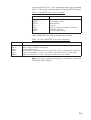
7.3 Preparing Programs for Automatic Message Transmission ......................................7-8
7.4 Transmitting in MARITEX System ........................................................................7-17
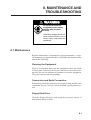
8. MAINTENANCE AND TROUBLESHOOTING
8.1 Maintenance ..............................................................................................................8-1
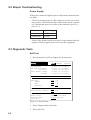
8.2 Simple Troubleshooting ............................................................................................8-2
8.3 Diagnostic Tests ........................................................................................................8-2
ITU TELEX CHANNELS/FREQUENCY LIST..................................... AP1-1
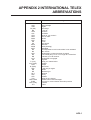
INTERNATIONAL TELEX ABBREVIATIONS .................................... AP2-1
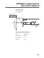
DIGITAL INTERFACE (IEC 61162-1 Edition 2) ................................. AP3-1
SPECIFICATIONS ................................................................................ SP-1
Declaration of conformity to type
iv
FOREWORD
FURUNO Electric Company thanks you for selecting and purchasing the FURUNO DP-6 NBDP
(Narrow Band Direct Printing) Terminal. We are confident you will discover why the FURUNO
name has become synonymous with quality and reliability. To get maximum performance from
your unit, please carefully read and follow the recommended procedures for operation and
maintenance.
The DP-6 is an advanced, microprocessor controlled NBDP Terminal designed to protect
teleprinting communications from radio signal mutilation due to interference in the radio signal
path. It provides dependable, fully automatic error-free telex communication with other ships,
as well as with any telex subscriber, in full compliance with all GMDSS requirements for
automatic radiotelex operation.
The microprocessor used in the DP-6 enables fully automatic operation of your radio station,
including automatic frequency scanning, unattended reception and transmission of messages,
automatic adjustment of transmitter frequency, and more. Operation is simplified by the use of
menus: Simply move the cursor to items on the screen that you want to select.
The DP-6 provides a complete line of word processing facilities in its Text Editor, where you
may create, edit and store multiple messages for later transmission.
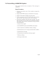
Features
• Simple operation by use of pop-up menus
• LCD displays information in easy-on-your-eyes white on black
• Automatic frequency control and message handling permit unattended operation
• Real time printing of incoming messages
• Storage capacity for 100 user channels
• Remote control of a transceiver by commands entered via the keyboard
• Inputs for IEC61162-1 2nd edition(NMEA0183 version 3.0) data, to display ship's
L/L position, water temperature, and more on the LCD
• Fully automatic radiotelex by use of macro operation
• Conforms to the following standards and regulations:
IMO Resolution A.806 (19), A.694 (17)
IEC 61097-11/9, 60945 (3rd edition), 61162-1 (2nd edition)
ITU-R M.625-3, M.490, M491-1
ITU-T F.130
ETS 300 067
Program number
TERMINAL UNIT
0550189020 (Version 1.22)
MAIN UNIT
0550187017 (Version 1.17)
MODEM
0550196017 (Version 1.18)
v
This page is intentionally left blank.
1. RADIOTELEX COMMUNICATION
1.1 General
Telex subscribers can attest to radiotelex as a reliable and efficient
method for sending and receiving teleprinter connections. Telex
subscribers, especially those who often use HF-band radio circuits,
will also attest that the telex connection is subject to interference
from a variety of sources, including atmospherics, fading and noise
disturbance. This interference plays havoc with radio signals, resulting in the receiving of information different from the intended
information. Thus a means must be provided to prevent mutilation
of radio signals by interference on HF-band radio.
Radiotelex communication today owes its reliability and efficiency
to error detection and correction. The ITU-R defined both a constant-ratio code for automatic error detection and requirements for
the error correction in Recommendation M.625-3.
1.2 Code Description
The DP-6 employs a 7-element synchronous code providing 27 =
128 combinations. Among these 128 combinations, there are 35
constant-ratio combinations having a ratio of 3 (Y) mark bits to 4
(B) space bits. Thus ratio is used to test the validity of each received character.
Of the 35 combinations, 32 are used for the required alphanumeric
teleprinter signals. The remaining three 7-element codes are used
exclusively for operational purposes. These are:
Idle Signal (ARQ Mode), Phasing Signal 1 (FEC Mode)
Idle Signal
RQ Signal (ARQ mode), Phasing Signal 2 (FEC Mode)
Transmission rate is 100 bauds. If the 4B/3Y ratio is disturbed due
to interference, the output of the receiver is blocked to restrict the
mutilated character from passing on to the teleprinter.
Frequency Shift
The frequency shift is 85 Hz with a center frequency of 1700 Hz,
as specified in ITU-R Recommendation M.625-3.
Space Tone Frequency 1700+85 = 1785 Hz
Mark Tone Frequency 1700-85 = 1615 Hz
1-1
1.3 ARQ Mode (A-Mode)
Description
The ARQ (Automatic Re-transmission request, or Automatic Request for repetition) Mode allows private communications between
any two stations using semi-duplex communication. Reception
confirmation is done to assure that each character is received correctly. Since the two stations (automatically) exchange identities,
this affords some degree of protection for confidential messages.
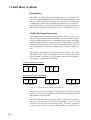
Traffic Exchange Sequence
In the ARQ mode two stations communicate directly with one another. One station sends information and receives controls signals,
while the other station receives information and sends confirming
control signals. The first station is the ISS (Information Sending
Station), and the second is the IRS (Information Receiving Station). These functions are interchangeable by a special control signal.
The station which initiates the call is the Master Station (MS). The
MS initiates the call by sending the selective identity code of the
called station, consisting of an RQ signal and two traffic information signals, listening between blocks.
Example: Identity Code XQKM
X
RQ
Q
Calling Block 1
K
M
RQ
Calling Block 2
Example: Identity Code PEARDBY
P
RQ
E
Calling Block 1
RQ
A
R
Calling Block 2
D
B
Y
Calling Block 3
Figure 1-1 How identity code is transmitted
The Slave Station (SS) recognizes own identity code received and
answers it is ready by sending a control signal. The calling station
then initiates normal traffic.
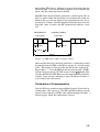
The ISS sends information in blocks of three characters. Each character is sent at the rate of 100 bauds, amounting to 70 ms for one
character or 210 ms for one character block. The block repetition
cycle is 450 ms, so there is 240 ms during each cycle that the ISS is
1-2
not sending. This time is taken up by propagation time from the
ISS to the IRS, 70 ms for the IRS to send its service information
signal, and the return trip back to the ISS.
The IRS listens between blocks and sends a control signal (CS1 or
CS2) to request either the next block, or retransmission of the last
block in the case of error. Request for retransmission may be repeated up to 32 times, until the completed block has been received
error-free. After 32 times, the ISS automatically initiates a new
call.
INFORMATION
3 Characters
CONTROL SIGNAL
1 Character
70 ms
70 ms
210 ms
450 ms
Figure 1-2 ARQ mode traffic exchange timing
Once an entire message is received (error-free), a station may switch
its function from the IRS to the ISS by means of a control signal
(CS3). This change is done by either the ISS by the sequence of "
Figure shift + ? ", or by the IRS operator by activating the "OVER"
control. Upon receipt of CS3, ISS answers with a
block. This
switches the ISS into IRS. However, the original Master and Slave
stations' status remains unchanged, since the Master Station always controls the radio circuit.
Termination of Communication
Only the ISS may terminate the established circuit. It does this by
sending three "idle signals ." The IRS and ISS exchange control
signals, each reverting to standby after acknowledging each other’ s
control signals. Then, the connection is cleared.
1-3
1.4 FEC Mode (B-Mode)
Description
The FEC mode is for one-way, uninterrupted transmission of messages, for example, weather forecasts and emergency bulletins, to
no one particular station or stations. The sending station is known
as the BSS (B-Mode Sending Station), the receiving station the
BRS (B-Mode Receiving Station).
This mode uses a simple forward-error correcting (FEC) technique
of sending each character twice at a 280 ms interval. The first transmission is termed DX (direct transmission), the second RX (repeated transmission).
Message: " a b c d e f g h i j "
First transmission:
Second transmission:
a
b
c
d
e
f
g
h
i
j
a b c d e f g h i j
280 ms
Output code ex.:
a b c ad b e c f d g e h f i g j h i j
Figure 1-3 FEC mode transmission technique
The receiving station tests the DX and RX characters for adherence to the 4-mark/3-space constant ratio, and prints only
unmutilated DX or RX characters, or prints a space if both are
mutilated.
Another version of the FEC mode is the FEC-selective mode. This
mode uses a call code for selective calling to one or more stations.
Only those stations with the correct code will receive the data correctly.
Initiating a Call
When a BSS initiates a broadcast call it transmits synchronizing
signals to align phasing of the BRS. Upon detection of this signal
the BRS’s are switched to the receiving condition and will remain
in this condition until the completion of the message. If the mutilated character error rate exceeds a certain percentage, the BRS
reverts to standby condition.
Termination of Communication
The sending station sends three consecutive idle signals α immediately after the last transmitted information signal in the DX position.
1-4
2. SYSTEM OVERVIEW
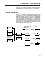
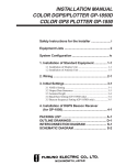
2.1 System Configuration
SSB RADIOTELEPHONE
24 VDC
MAIN UNIT
DP-6
DSC
NAV AID
24 VDC
TERMINAL UNIT
IB-581
24 VDC
PRINTER
PP-510
_ _____: Standard supply
- - - - - -: Optional supply
Figure 2-1 System configuration
2-1
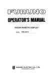
2.2 Turning on the System
There is no particular order for turning on the units of the system.
The figure below shows the location of power switches on the units
of the system. Note that it takes about six seconds for the LCD to
light after the power is turned on.
POWER switch
MAIN UNIT
POWER switch
TERMINAL UNIT
POWER switch
PRINTER
Figure 2-2 Main unit, terminal unit and printer
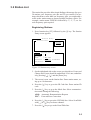
2.3 Equipment Description
Terminal Unit
The terminal unit consists of a 9" visual display, a floppy disk drive
and a keyboard. The floppy disk drive provides for unlimited storage of files on floppy disks. Controls for power and adjustment of
display brilliance and contrast are provided on the front panel.
When the terminal unit is turned on the communication status display appears. This is where all phases of communication begin.
1:File 2:Edit 3:Operate 4:Window 5:Station 6:System 7:WRU 8:HR 9:Over 10:Break
1996-11-15 13:26:45:45
Caps Eng
Station Name
:
Frequency (T/R) :
/
(kHz) Comm Mode : Auto
Comm Status
: Connect Send Lock Error
Sending Volume :
(%)
ARQ Error : 0
ARQ Time : 0(sec)
Figure 2-3 Communication status display
2-2
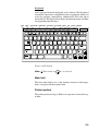
Keyboard
unit is operated from the keyboard, and is almost 100% keyboard
controlled. Operation is simplified by the use of menus which you
access by pressing a function key, numbered F1-F10 at the top of
the keyboard. The figure below shows the function menus and their
corresponding function keys.
FILE EDIT OPERATE WINDOW STATION SYSTEM WRU HR OVER BREAK
Esc
F1
F2
F11
F12
F4
F3
F5
F7
F6
F9
F8
~
!
@
#
$
%
^
& 7
*
`
1
2
3
4
5 C
6
7
8
Q
Tab
W
A
Caps Lock
E
S
R
D
T
F
Y
G
(
8
9
9
U 4
H
Num
Lock
F10
I
J 1
Prt Sc
Scroll
Lock
)
*
O 6
K 2
_
+
-
=
P
L 3
:
Z
Fn
Ctrl
X
C
V
B
N
M 0
{
}
|
]
\
+
"
Enter
'
<
>
?
,
.
/
Alt
Alt
Backspace
[
;
Shift
Delete
Break
0
5
Insert
Pause
SysRq
/
Shift
PgUp
Ctrl
Home
End
PgDn
Figure 2-4 Keyboard
Note: C (Euro mark) on
%
5 C
key is not used.
Main Unit
The main unit mainly acts as the interface between radio equipment, navigator and the terminal unit.
Printer (option)
The printer prints messages. Refer to its operator's manual for operation.
2-3
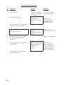
2.4 Function Keys, Menu Operation
The function keys at the top of the keyboard control most operations of this unit through a menu system.
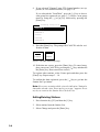
Menu Conventions
Inverse video
As you move the cursor down through a menu, selected item initially shown as white on black, inverses to black on white. This
highlighting indicates that it is available for selection.
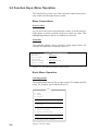
Underline
The underline shows current selection. In the figure below, for
example, the underline is beneath "Receive".
Operation
Station
Start Time
Stop Time
Receive/Send
File to send
Timer Operation Set Up
: OP1
: NAGASAKI
: 8:35: 0
: 9:10: 0
: Receive Send
:
Figure 2-5 The auto operation set up screen
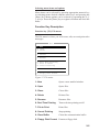
Basic Menu Operation
Selecting menus
Press appropriate function key to open a menu. To display the File
menu, for example, press function key [F1].
File
1: New
2: Open
3: Close
4: Delete
5: Rename
6: Real Time Printing
7: File to Print
8: Cancel Printing
9: Clear Buffer
0: Floppy Disk Format
2-4
Figure 2-6 File menu
Selecting menu items and options
Menu items can be selected by pressing appropriate numeric key
or selecting menu desired with the arrow keys and pressing the
[Enter] key. Menu options can be selected by operating the [←]/
[→] keys. Press the [Enter] key to register selection and close the
menu.
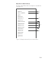
Function Key Description
Function key [F1]: File menu
The File menu is where you will create, edit, save and print telex
messages.
File
1: New
2: Open
3: Close
4: Delete
5: Rename
6: Real Time Printing
7: File to Print
8: Cancel Printing
9: Clear Buffer
0: Floppy Disk Format
Figure 2-7 File menu
1: New
Opens a new untitled window.
2: Open
Opens files.
3: Close
Closes files
4: Delete
Deletes files.
5: Rename
Renames files.
6: Real Time Printing
Turns real time printing on/off.
7: File to Print
Prints files.
8: Cancel Printing
Stops printing.
9: Clear Buffer
Clears the communication buffer.
0: Floppy Disk Format Formats a floppy disk.
2-5
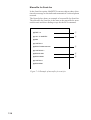
Function key [F2]: Edit menu
The Edit menu provides a full line of editing features. This menu is
only operative while creating a message.
Edit
1: Undo
2: Cut
3: Copy
4: Paste
5: Select All
6: Search
7: Replace
8: Goto Top
9: Goto Bottom
0: Goto Line
A: Change Text
Figure 2-8 Edit menu
2-6
1: Undo
Cancels the last change (cut, copy or paste).
2: Cut
Removes the selected text and stores it in
the paste buffer. (Previous text in the paste
buffer is cleared.)
3: Copy
Copies the selected text and stores in the
paste buffer. (Previous text in the paste
buffer is cleared.)
4: Paste
Inserts the text stored in the paste buffer at
the current location of the cursor.
5: Select All
Selects the entire current file for cut and
copy.
6: Search
Searches a file for a character string.
7: Replace
Replaces a word with a different word or
character string.
8: Goto Top
Brings the cursor to the top line of the current file.
9: Goto Bottom
Brings the cursor to last line of the current
file.
0: Goto Line
Moves the cursor to the desired line in the
current file.
A: Change Text
Switches between the display window 1 and
2.
Function key [F3]: Operate menu
The Operate menu controls transmitting and receiving.
Operate
1: Call Station
2: Macro Operation
3: File to Send
4: Cancel Sending
5: Scan (Start/Stop)
6: Manual Reception
7: Timer Operation
8: High Tension ON
9: Manual Calling
0: Set Frequency
Figure 2-9 Operate menu
1: Call Station
Selects a station from the station list.
2: Macro Operation
Enables fully automatic operation.
3: File to Send
Selects a file (to transmit).
4: Cancel Sending
Stops sending a file.
5: Scan Start/Stop
Starts/stops frequency scanning.
6: Manual Reception
Selects communication mode for reception; AUTO/ARQ/FEC.
7: Timer Operation
Timer programming.
8: High Tension ON/OFF Turns on/off transmitter high voltage on a FURUNO radio.
9: Manual Calling
Sets Tx mode and subscriber's ID
number in manual calling.
0: Set Frequency
Sets Tx and Rx frequencies in
manual calling.
2-7
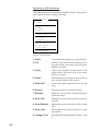
Function key [F4]: Window menu
The Window menu displays data together with current screen.
Window
1: Display NMEA Data
2: Calendar
3: Remote A
4: Remote B
(TX/RX)
(DSC)
5: Distress Frequency Table
Figure 2-10 Window menu
2-8
1: Display NMEA Data
Displays NMEA data: position, speed,
Heading, water temperature and depth.
2: Calendar
Displays desired calendar month and year.
3/4: Remote A/B
Entering commands on this screen enables
remote control of a FURUNO radio transceiver and DSC terminal connected to Remote A and Remote B terminals.
5: Distress Frequency Table
Displays all distress frequencies.
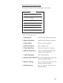
Function key [F5]: Station menu
The Station menu provides for storage of stations, timer programs,
channels, and various ID codes.
Station
1: Station Entry
2: Timer Operation Entry
3: Scan Entry
4: User Channel Entry
5: Answerback Code Entry
6:
7:
8:
9:
Group ID Entry (4/5 digit)
Group ID Entry (9 digit)
Select ID Entry (4/5 digit)
Select ID Entry (9 digit)
Figure 2-11 Station menu
1: Station Entry
Registers stations.
2: Timer Operation Entry
Registers timer programs.
3: Scan Entry
Creates scan groups for scanning.
4: User Channel Entry
Registers user channels.
5: Answerback Code Entry Registers own ship's answerback code.
6: Group ID Entry
Registers own ship's group ID codes.
(4/5 digit)
7: Group ID Entry
Registers own ship's group ID codes.
(9 digit)
8: Select ID Entry
Registers own ship's selective ID codes.
(4/5 digit)
9: Select ID Entry
Registers own ship's selective ID codes.
(4/5 digit)
2-9
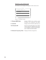
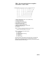
Function key [F6]: System menu
The System menu is mainly for use by technicians and includes
diagnostic tests (self test). To change settings, select Change on
the Setup line and operate arrow keys to select item and option.
Press the [Enter] key to register selection and close the menu.
Setup
System
Lock
Change
Default
Slave Delay
BK Timing PreTone
PostTone
Mute Timing PreBK
PostBK
5
10
0
0
0
Modem Output Level
0 dBm (-30 - +10 dBm)
MIF Tune
Freeze
AGC
Emission
OFF
OFF
OFF
OFF
O
O
O
O
TX/RX MSG Save
Edit Before sending
OFF
OFF
O N
O N
Time System
Time & Date
Display Mode
Self Test
OFF UTC SMT JST
1997/3/16/10:00:00
Normal Reverse
msec
msec
msec
msec
msec
(0- 50
(0-100
(0- 20
(0- 20
(0- 20
msec)
msec)
msec)
msec)
msec)
N
N
N
N
Figure 2-12 System menu
Setup
Locks, enables change or restores default
system settings.
Slave Delay
Sets the length of the slave delay timing
in the ARQ mode.
BK Timing PreTone
Sets the timing for the leading edge of
the BK signal in the ARQ mode.
BK Timing PostTone Sets the timing for the trailing edge of
the BK signal in the ARQ mode.
Mute Timing PreBK
Sets the timing for the leading edge of
the mute signal in the ARQ mode.
Mute Timing PostBK Sets the timing for the trailing edge of
the mute signal in the ARQ mode.
Modem Output Level Sets modem output level.
MIF Tune
2-10
Turn on to send antenna coupler tuning
command. (Requires FURUNO Radio
Equpment.)
MIF Freeze
Turn on to send "freeze" command to
radio equipment connected. (Requires
FURUNO radio equipment.)
MIF AGC
Turn on to automatically control gain in
telex mode. (Requires radio equipment
which supports AGC command in MIF
format.)
MIF Emission
Turn on to automatically change mode
at radio equipment to telex. (Requires
radio equipment which supports Emission command in MIF format.)
TX/RX MSG Save
Turn on to automatically save incoming
and outgoing messages to floppy disk.
Edit Before Sending "No" transmits keying operation one by
one. "Yes" transmits message only when
the [Enter] key is pressed after confirming text typed.
Time System
Select Time system. SMT is local time
and JST is Japan standard time.
Time & Date
Enter Date and time manually. If a navigation device is connected, the time is
automatically set when the power is
turned on or whenever the time system
is switched. Manual entry takes priority over automatic entry. If there is no
the navigation data input, it takes more
than extra 10 seconds for automatic initial settings.
Display mode
Select display mode between normal and
reverse.
Function key [F7]: WRU (Who Are You?)
In the ARQ mode, requests other station's answerback code.
Function key [F8]: HR (Here Is)
In the ARQ mode, sends your ship's answerback code.
2-11
Function key [F9]: OVER
In the ARQ mode, changes the direction of traffic; the information
receiving station becomes the information sending station, the information sending station becomes the information receiving station.
Function key [F10]: BREAK
Disconnects the communications line.
2-12
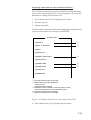
3. PREPARATIONS FOR
TRANSMISSION AND RECEPTION
This chapter provides the procedures necessary for preparing the
DP-6 for transmitting and receiving. For automatic telex, you will
need to register the following;
• Your ship's ID and answerback codes
• Stations
• Timer programs
• Scan channel groups
• User channels
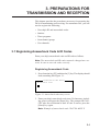
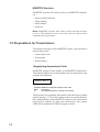
3.1 Registering Answerback Code & ID Codes
Enter your ship's answerback code and ID code as follows.
Note: The answerback and ID codes cannot be changed once entered; be sure to enter the codes correctly.
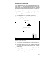
Registering Answerback Code
1. Press function key [F5] and then the [5] key. The display should
look something like Figure 3-1.
Answerback Code Entry
Answerback Code
Figure 3-1 Answerback code entry screen
2. Enter your ship's answerback code (max. 20 characters, including spaces) and press the [Enter] key. The prompt OK/CANCEL asks for verification of data. If code is correct, press the
[Enter] key again.
Note: Example of answerback code 12345789 ABCF X.
3-1
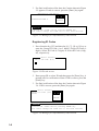
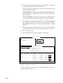
3. For final verification of the data, the Caution shown in Figure
3-2 appears. If code is correct, press the [Enter] key again.
Answerback Code Entry
Answerback Code
O K
123456789 FURU X
Cancel
Caution
Confirm the 'CODE' before pressing ENTER key.
You cannot change the CODE once it has been entered.
Figure 3-2 Message for confirmation of code entered
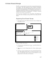
Registering ID Codes
1. Press function key [F5] and then the [6], [7], [8] or [9] key to
enter the Group ID Code (4 or 5 digits), Group ID Code (9
digits), Select ID Code (4/5 digits) or Select ID Code (9 digits), respectively.
Select ID Entry
Select ID Code (4/5)
Figure 3-3 ID code screen
2. Enter group ID or select ID and then press the [Enter] key. A
prompt asks for verification of data. If ID is correct, press the
[Enter] key.
3. For final verification of the data, the Caution shown in Figure
3-4. If ID is correct, press the [Enter] key again.
Select ID Entry
Select ID Code (4/5)
12345
O
K
Cancel
Caution
Confirm the 'CODE' before pressing ENTER key.
You cannot change the CODE once it has been entered.
Figure 3-4 Message for confirmation of code entered
3-2
3.2 Station List
The station list provides abbreviated dialing with storage for up to
50 stations, one frequency pair (Rx and Tx) per station. For stations which have more than one frequency pair, you might add a
suffix to the station name to denote multiple frequency pairs. For
example, station name FURUNO followed by -1, -2, -3, etc. for
each frequency pair required.
Registering Stations
1. Press function key [F5] followed by the [1] key. The Station
Entry screen appears.
Station Entry
Station List
Create
Change
Station Set Up
Station :
ID Code :
Mode
: ARQ FEC
CH/Table : Channel ScanTable
Num/Table:
Figure 3-5 Station entry screen
2. On the right-hand side on the screen you should see Create and
Change and Create should be underlined. If it is not, underline
it by pressing [ ], [ ] and the [Enter] key.
3. The cursor is now on the Station line. Enter station name, using up to 18 characters.
4. Press the [ ] key to go to the ID Code line. Enter station ID
code.
5. Press the [ ] key to go to the Mode line. Select communication mode among the following;
ARQ: Automatic Retransmission Request
FEC: Forward Error Correction
6. Press the [ ] key to go to the CH/Table line. Select ScanTable
with [ ] or [ ] key to choose channel.
7. Press the [ ] key to go to the Num/Table line.
3-3
8. If you selected "Channel" enter ITU channel number (see appendix) or User channel number (see page 3-9).
If you selected the "ScanTable", press the [ ] key to show a
scan group list registered (see page 3-7). Select a scan group
name by using the [ ] or [ ] key followed by pressing the
[Enter] key.
Scanning Group List
MARITEX-A
MARITEX-B
MARITEX-C
FURUNO
CHOUSHI
MARITEX-F
9. Press the [Enter] key. The prompt OK/CANCEL asks for verification of data.
CREATE
CHANGE
O
K
CANCEL
Figure 3-6 OK/CANCEL prompt
10. If the data are correct, press the [Enter] key. (To cancel entry,
place cursor on CANCEL by pressing the [ ] key, and then hit
the [Enter] key. Data entered are erased.)
To register other stations, select Create again and then press the
[Enter] key. Repeat steps 3 – 10.
To confirm the data registered, press the [ ] key to get into the
Station Set Up window.
Note: If you enter a station which exists the indication "Station by
that name already exists. Press any key to escape." appears. Press
any key to return to the Station List. Check the list.
Editing/Deleting Stations
1. Press function key [F5] and then the [1] key.
2. Select station from the Station List.
3. Select Change and press the [Enter] key.
3-4
4. Do one of the following;
Edit station:
Use [ ], [ ] and the [Backspace] key to make
corrections.
Delete station: Erase station name with the [Backspace] key.
5. Press the [Enter] key twice.
6. Press the [Esc] key.
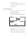
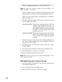
3.3 Timer Programming
A built-in timer allows you to automatically receive and transmit
files. 10 timer programs can be registered.
Registering Timer Programs
1. Press function key [F5]. Press the [2] key to select Timer Operation Entry. The screen should look something like Figure 37.
Timer Operation Entry
Timer Operation List
Create
Change
Timer Operation Set Up
Operation
Station
Start Time
Stop Time
Receive/Send
File to Send
:
:
: 0: 0: 0
: 0: 0: 0
: Receive Send
:
Figure 3-7 Timer operation entry screen
2. If Create is not underlined, press [ ], [ ] and the [Enter] key
to underline it.
3. Enter a suitable operation name on the Operation line. Any
alphanumeric characters may be used. See note 2 on the next
page.
4. Place the cursor on the Station line. Press the [ ] key to display the Station List. Select a station and press the [Enter] key.
3-5
5. Press the [ ] key to advance the cursor to the Start Time line.
Enter start time in 24-hour notation. To have the operation start
at 8:35, for example, the keying sequence would be;
[0] [8] [3] [5] [0] [0]
6. Press the [ ] key to advance the cursor to the Stop Time line.
Enter stop time.
7. Press the [ ] key to advance the cursor to the Receive/Send
line. Select operation category; Receive or Send.
8. For send, insert floppy disk in drive and designate the file to
send. Press the [ ] key to advance the cursor to the File to
Send line. Press the [ ] key to display the file list, select a file,
and press the [Enter] key.
9. Press the [Enter] key.
10. Press the [Enter] key. The operation name appears in the Timer
Operation List. See note 2 and 3.
Note 1: To change a timer program, select it on the Timer Operation List, select Change and press the [Enter] key. Enter new data.
Note 2: If the operation name entered already exists, the display
shows the following message: Operation name already exists. Press
any key to escape. Press any key and change the operation name.
Note 3: If the station name entered has not been registered, the
display shows the following message: Station by that name does
not exists. Press any key to escape. Press any key and register the
station as shown on page 3-3.
Editing/Deleting Timer Programs
1. Press function key [F5] and the [2] key.
2. Select timer program from the Timer Program List.
3. Select Change and press the [Enter] key.
4. Do one of the following;
Edit program:
Use [ ], [ ] and the [Backspace] key to
make corrections.
Delete program: Erase operation name with the [Backspace]
key.
5. Press the [Enter] key twice.
6. Press the [Esc] key.
3-6
3.4 Scan Channel Groups
The DP-6 can automatically control radio equipment through channel scanning. The radio equipment scans a number of channels
(according to your selection), stopping when your own ID code is
detected in an incoming signal. The transmitter is tuned to the corresponding transmitter frequency, the communication link is established and the traffic is automatically exchanged. Scanning
resumes once the link is disconnected.
You may store a maximum of 10 scan groups, 20 channels per
group. Note that scanning is only possible in the ARQ and FEC
modes.
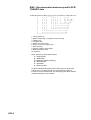
Registering Scan Channel Groups
1. Press function key [F5] followed by the [3] key to display the
Scan Entry screen.
Scan Entry
Scanning Group List
Create
Change
Scanning Set Up
Group Name
Ch Dwell Time
Mode
Auto Search
No
1
2
3
4
5
▼6
Channel
:
: 4.5 sec (2.7-4.5 sec)
: AUTO ARQ FEC
: OFF ON
Rx Freq
Tx Freq
Pass/Scan
Pass/Scan
Pass/Scan
Pass/Scan
Pass/Scan
Pass/Scan
Figure 3-8 Scan entry screen
2. If Create is not underlined, press [ ], [ ] and the [Enter] key
to underline it.
3. The cursor is on the Group Name line. Enter suitable group
name.
4. Press the [ ] key to advance the cursor to the CH Dwell Time
line. Enter channel dwell time in seconds. Dwell time is the
time in seconds the receiver waits on each channel in a scan
group before it selects the next frequency.
3-7
5. Press the [ ] key to advance the cursor to Mode, and then select the communication mode; AUTO, ARQ or FEC.
Note: To register the Scanning Channel Group for ARQ, select
ARQ. For FEC, select FEC.
AUTO is used to register scanning channel group when both
ARQ and FEC exist in the same Scanning Channel Group.
When you select scan group by call sration menu, set Mode to
FEC (See Page 5-7).
6. Press the [ ] key to advance the cursor to Auto Search. Select
Auto Search to ON or OFF.
Auto Search ON: Radio stops scanning when it finds the
strongest signal (highest S/N ratio). To
find strongest signal, the radio scans all
this channel, which may take some time.
Therefore, use this setting where signal
propagation is poor.
Auto Search OFF: Radio stops scanning on the first signal it
finds. We recommend that you set Auto
Search to OFF where signal propagation
is good.
7. Advance the cursor to line no. 1 in the Scanning Set Up window. Enter channel number (ITU or user channels) and press
the [ ] key to select "Scan".
8. Press the [ ] key to advance the cursor to line No. 2. Enter
channel number.
9. Enter other channel numbers and then press the [Enter] key.
10. Press the [Enter] key again to save the data.
To register another scan group, repeat steps 2 – 9.
Note: When the scan group memory is full the DP-6 displays "Scan
group information full."
Editing/Deleting Scan Channel Groups
1. Press function key [F5] and the [3] key. Select scan group from
the Scanning Group List.
2. Select Change and press the [Enter] key.
3. Place the cursor on the line (channel) to change.
3-8
4. Do one of the following;
Editing channels: Press the [Backspace] key to delete the channel number and then enter new channel number.
Adding channels: Enter channel number on a blank line.
Deleting channels: Delete group name with the [Backspace]
key.
Disabling channels temporarily: Press the [ ] key to underline Pass.
5. Press the [Enter] key twice.
6. Press the [Esc] key.
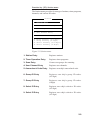
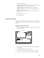
3.5 User Channels
The user channel list provides storage for up to 100 user channels,
numbered 0 – 99. Note that user channels may be used in channel
scanning.
Registering User Channels
1. Press function key [F5] and then the [4] key. The User Channel
Entry screen appears.
User Channel Entry
Channel List
Create
Change
Channel Set Up
Channel :
Tx Freq :
Rx Freq :
0.00
0.00
Figure 3-9 User channel entry screen
2. If Create is not underlined, press [ ], [ ] and the [Enter] key
to underline it.
3. Enter channel number on the Channel line.
4. Advance the cursor to the Tx Freq line. Enter Tx frequency.
5. Advance the cursor to the Rx Freq line. Enter Rx frequency.
3-9
6. Press the [Enter] key.
7. Press the [Enter] key. Channel number entered appears in the
Channel List.
To register another user channel, repeat steps 2 – 7.
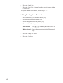
Editing/Deleting User Channels
1. Press function key [F5] and then the [4] key.
2. Select channel from the Channel List.
3. Select Change and press the [Enter] key.
4. Do one of the following;
Edit channel:
Use [ ], [ ] and the [Backspace] key to
make corrections.
Delete channel: Erase channel number with the [Backspace]
key.
5. Press the [Enter] key twice.
6. Press the [Esc] key.
3-10
4. FILE OPERATIONS
This chapter mainly describes how to create, save, edit and print
files. The Edit menu provides a full lineup of editing facilities including search and replace.
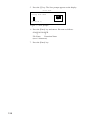
4.1 Creating Files
1. Press function key [F1] to display the File menu.
File
1: New
2: Open
3: Close
4: Delete
5: Rename
6: Real Time Printing
7: File to Print
8: Cancel Printing
9: Clear Buffer
0: Floppy Disk Format
Figure 4-1 File menu
2. Press the [1] key.
3. Type your message.
Note: Do not use lower case letters, #, &, *, $ or % in telex messages. Also, do not put “$$$” (three successive $s) in the middle of
a Tx message, but at the end. The communication line is automatically disconnected when the DP-6 detects this string.
4-1
4.2 Saving a File
Before you can save a file to a floppy disk, the disk must be formatted. 2HD Type is only available.
Formatting Floppy Disks
1. Press function key [F1].
2. Press the [0] key to select "Floppy Disk Format".
3. Press the [↑] key to select "YES".
4. Press the [Enter] key.
5. Insert a new floppy disk and press the [Enter] key.
Saving a File
1. Press function key [F1] to display the File menu.
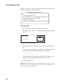
2. Press the [3] key. The screen should look something like Figure 4-2.
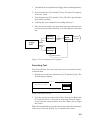
Close Text
Save file ?
Yes
( UNTITLED1
)
No
Figure 4-2 Close text screen
3. Press the [Enter] key. Enter file name, using up to eight characters.
You may use any alphabet or numeric on the keyboard. But
you may not use the following punctuation symbols;
!
|
:
"
>
< ;
You may add an extension at the end of the file name, for example, .TXT, to distinguish text file from macro file.
4. Press the [Enter] key.
Note: When the working area is full, the message "File can't open"
appears. Then, you would close a file to clear a working area in
order to open the file desired.
4-2
4.3 Editing Files
Cutting and Pasting Text
You can delete, move and copy text by using the Cut, Copy and
Paste functions in the Edit menu.
Edit
1: Undo
2: Cut
3: Copy
4: Paste
5: Select All
6: Search
7: Replace
8: Goto Top
9: Goto Bottom
0: Goto Line
A: Change Text
Figure 4-3 Edit menu
Cutting text
1. Place the cursor on the first character of the text to be cut.
2. Highlight the text to be cut by pressing and holding the [Shift]
key while pressing the [ ]. If you highlight text which you do
not want to cut, press the [ ] to adjust the highlight.
<[1]UNTITLED1>
CONGULATULATION ON YOUR CHOICE OF DP-6
INMARSAT B MOBILE EARTH STATION.
WE ARE CONFIDENT THAT YOU WILL ENJOY MANY YEARS OF
OPERATION WITH THIS FINE PIECE OF EQUIPMENT
Figure 4-4 The highlight
3. Press function key [F2] and the [2] key. The highlighted text is
cut and the remaining text is reformatted.
If a mistake is made, you can restore the text by immediately selecting Undo in the Edit menu.
4-3
Pasting text
To paste the cut text to a new location;
1. Place the cursor at the exact spot in the message where the cut
text is to start.
2. Press function key [F2] and the [4] key.
Copying and Pasting Text
You may copy a portion of text and paste it elsewhere.
1. Select the text to copy (see the "cutting" procedure above ).
2. Press function key [F2] and the [3] key.
The text selected is copied in the paste buffer memory where
the cut or copied text is stored. The display returns to the normal screen.
3. Place the cursor at the exact spot in the message where the
copied text is to start.
4. Press function key [F2] and the [4] key.
Clearing the Paste Buffer
Press function key [F1] and the [9] key.
Undo
Use the Undo feature to return the file to its most recent state. For
example, you have cut text but want to restore it. Then, you would
select Undo in the Edit menu to restore the text to its most recent
location.
Select All
The Select All feature lets you select all of the file currently displayed. This feature can be useful when you want to combine files.
The procedure below explains how to tack the file loaded in working memory 1 onto the end of the file loaded in working memory
2.
4-4
1. Load the file to be copied from a floppy disk in working memory
1.
2. Press function key [F2] and the [5] key. The entire file appears
in inverse video.
3. Press function key [F2] and the [3] key. The file is placed in the
paste buffer memory.
4. Load the file to be combined in working memory 2.
5. Place the cursor at the exact spot in the message where the text
now in the paste buffer memory is to start and press the [Ins]
key.
Working
Memory 1
1
Open
file
3
Open
file
Floppy
Disk
2
Transfer
(copy)
Paste
Buffer
Memory
Holds cut or
copied text
Working
Memory 2
4
Paste (Combine)
Figure 4-5 Cut and paste flow diagram
Searching Text
The Search feature lets you search for text in a forward or backward direction.
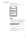
1. Display a text and press function key [F2] and the [6] key. The
Search display appears.
Search
Dir
Search string :
Forward
Backward
To quit: ESC
Figure 4-6 Search screen
2. Type the word you want to find. Select Forward or Backward
to search the file in a forward or backward direction respectively from the cursor position. Press the [Enter] key to begin
the search.
When the unit finds the word, the cursor stops at the first character
of the word. Press the [Enter] key to continue the search.
4-5
Replacing Text
The Replace feature helps you replace every occurrence of a word
or phase with another word or phase in a file.
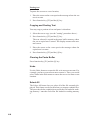
1. Press function key [F2] and the [7] key. The Replace display
appears.
Replace
Search string :
Replace with :
Dir
Mode
Forward
Query
Backward
All
To quit: ESC
Figure 4-7 Replace screen
2. Type the word you want to replace on the "Search string " line.
3. Press the [ ] to select "Replace with." Type the new word.
4. Select Forward or Backward to search the file in a forward or
backward direction respectively from the cursor position.
5. Select whether you want to be queried or not each time the
word is found.
Query: Stop at each occurrence of word to answer yes or no
to replacement.
All:
Replace every occurrence of word without stopping
to confirm.
6. Press the [Enter] key to start the replacement.
Goto Line
This feature places the cursor at the head of a line desired. Press
function key [F2] and the [9] key. The following display appears.
Goto Line
Jump to Line No. :
Figure 4-8 Goto line screen
Key in line number and press the [Enter] key. The cursor shifts to
the head of the line selected.
4-6
4.4 Opening Files
Two working areas (called working area 1 and working area 2) are
provided to which you can load a file, and one file may be displayed on the LCD.
FLOPPY DISK
WORKING
AREA (2)
File
1
File
2
LCD
one file
DISPLAY
Figure 4-9 Working memories
Opening a File
1. Press function key [F1] to display the File menu.
2. Press the [2] key. A chronological list of files on the floppy
disk appears.
3. Select a file. Press the [Enter] key.
The file appears and the title bar shows the file name. You may
repeat this procedure to load another file into a working area.
Switching Between Files
Two files can be opened and one displayed on the LCD. To switch
between files do the following;
1. Press function key [F2].
2. Press the [A] key to switch files.
4-7
4.5 Renaming Files
To rename a file;
1. Press function key [F1].
2. Press the [5] key.
3. Select file and press the [Enter] key.
4. Enter new name.
5. Press the [Enter] key.
4.6 Saving a File Under a New Name
You may save a file under a new name as follows;
1. Open a file.
2. Edit the file as necessary.
3. Press function key [F1].
4. Press the [3] key to clear the screen.
5. Press the [Y] key.
6. Press the [Backspace] key to erase the original name and then
enter a new name.
7. Press the [Enter] key.
4.7 Deleting Files
1. Press function key [F1].
2. Press the [4] key.
3. Select file to delete and then press the [Enter] key.
4. Press the [Enter] key again. (To cancel, press the [ ] key followed by the [Enter] key.)
4-8
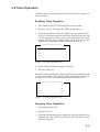
4.8 Real Time Printing
An incoming or outgoing message can be printed out while it is
being received or transmitted.
1. Press function key [F1] to display the File menu.
2. Press the [6] key to turn real time printing on/off.
PRINT appears in inverse video when real time printing is on.
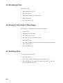
4.9 Printing Files
You can print a file as follows;
1. Press function key [F1].
2. Press the [7] key.
3. Select file and press the [Enter] key.
4. Press the [Y] key.
If the file could not be printed, "Cannot print. Check connection
between printer and terminal. Press any key to escape." is displayed.
4-9
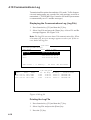
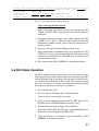
4.10 Communications Log
Transmission/Reception date and time, ID, mode, Tx/Rx frequencies and station name are recorded for each message received or
transmitted. ("TX/RX MSG Save" must be ON in the System menu
to automatically save Tx and Rx messages.)
Displaying the Communications Log (Log File)
1. Press function key [F1] and then the [2] key.
2. Select Log File and press the [Enter] key. A list of Tx and Rx
messages appears. See Figure 4-10.
Note: The Log File can store about 230 communication files. When
it becomes full, an error message appears to alert you. If this occurs, delete all log files.
Open Text
Load/Merge(TAB:Change)
File Name
Size Date & Time
LOG FILE
TELEX
NBDP
DO-5
File Count :
Date
Time
Mode
12-13 14:17 14:19 FEC
12-13 14:19 14:20 FEC
12-13 14:20 14:23 FEC
95k
136k
28k
41k
4
96-12-13
96-01-08
96-01-09
96-02-12
Memory :
14:20
20:32
20:31
20:30
4k Used
96k Avairable
[1]B:\LOG_FILE
ID TX Freq. RX Freq.
1234
8765.00 8965.00
1234
8765.00 8965.00
1234
8765.00 8965.00
Station name
CHOUSHI-8M
CHOUSHI-8M
CHOUSHI-8M
Figure 4-10 Log file
Printing the Log File
1. Press function key [F1] and then the [7] key.
2. Select Log File and press the [Enter] key.
3. Press the [Y] key.
4-10
5. TRANSMISSION, RECEPTION
This chapter shows you how to transmit and receive Telex messages. Also included are the procedures for frequency scanning,
and automatic operation.
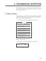
5.1 Manual Calling
The simplest way to communicate with a Telex subscriber is Manual
Calling. For the ARQ mode, you may display beforehand the message to send or type message manually.
1. Press function key [F3] to display the Operate menu.
Operate
1: Call Station
2: Macro Operation
3: File to Send
4: Cancel Sending
5: Scan (Start/Stop)
6: Manual Reception
7: Timer Operation
8: High Tension ON
9: Manual Calling
0: Set Frequency
Figure 5-1 Operate menu
2. Press the [0] key. The Set Frequency screen appears.
Set Frequency
Tx Freq:
0.00
RX Freq:
0.00
Figure 5-2 Set frequency screen
5-1
3. Input frequency pair. This can only be done with FURUNO
transceivers.
For other makes of transceiver, set a frequency pair at the transceiver. Omit steps 1, 2 and 3.
4. Press the [Enter] key.
5. Press function key [F3] again and then the [9] key. The following screen appears.
Manual Calling
Mode : ARQ FEC
ID
:
Figure 5-3 Manual calling screen
6. Select communication mode.
7. Press the [ ] key and input party's ID number.
8. Press the [Enter] key to connect the communication line. Then,
the line will be connected a short while.
For ARQ mode, follow the next procedure. For FEC mode,
type your message and go to step 13.
9. Press function key [F7] (WRU). The party's answerback code
appears on the screen.
Note: Step 9 and 10 are needed for ship to ship calling only.
10. Press function key [F8] (HR). You ship's answerback code is
sent to the party.
11. Press the [Enter] key and type your message.
12. If you want to the party's response, press function key [F9]
(Over).
13. Press function key [F10] to disconnect the line.
5-2
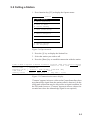
5.2 Calling a Station
1. Press function key [F3] to display the Operate menu.
Operate
1: Call Station
2: Macro Operation
3: File to Send
4: Cancel Sending
5: Scan (Start/Stop)
6: Manual Reception
7: Timer Operation
8: High Tension ON
9: Manual Calling
0: Set Frequency
Figure 5-4 Operate menu
2. Press the [1] key to display the Station List.
3. Select the station you wish to call.
4. Press the [Enter] key to establish connection with the station.
1:File 2:Edit 3:Operate 4:Window 5:Station 6:System 7:WRU 8:HR 9:Over 10:Break
1996-11-15 14:28 (JST)
Caps
Station Name
: CHOUSHI-8M
Frequency (T/R) :
8765.00 / 8965.00(kHz) Comm Mode :ARQ
Comm Status
: Connect Send Lock Error
Sending Volume : 100(%)
ARQ Error : 0
ARQ Time : 0(sec)
Figure 5-5 Communication status display
"Connect" appears in inverse video on the Comm Status line when
an acknowledge signal from the station called is detected. (In the
ARQ mode connection may be delayed due to signal condition. In
the FEC mode, however, "Connect" appears in inverse video a few
seconds later since the acknowledge signal is not required.)
5-3
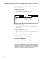
5.3 Transmitting a File from a Floppy Disk or the Text Screen
You may send a file from a floppy disk or the Text Screen as follows after calling a station.
From a Floppy Disk
1. Press function key [F3] and then the [3] key.
2. The Send screen appears.
Send File
File Name
Size
LOG FILE
TELEX
NBDP
DO-5
1k
1k
1k
1k
To select : ENTER
Date & Time
1996/11/15
1996/11/15
1996/11/15
1996/11/15
14:23
20:32
20:31
20:30
To view : SPACE
To quit : ESC
Figure 5-6 Send file screen
3. Select the file you wish to send. Then, press the [Enter] key to
transmit the file.
From the text screen 1 or 2
1. Prepare a message at the text screen 1 or 2 (working area 1 or
2).
2. Press function key [F3] and then the [3] key.
3. Press the [Enter] key to transmit the file.
Stopping Transmission
1. Press function key [F3] and then the [4] key.
2. Send Canceled appears on the screen. Transmission is stopped
but the line is still connected.
If the receiving station (IRS) reverses the communications direction while the sending station is transmitting a file, as many as six
characters from the end of the message may not be transmitted,
although they are displayed on the sending station’s LCD.
5-4
5.4 Selecting Receive Mode
1. Press function key [F3] and then the [6] key.
2. Select receive mode;
AUTO: Automatic operation in ARQ and FEC
ARQ:
International radiotelex ARQ mode
FEC:
International radiotelex FEC mode
3. Press the [Enter] key. The reception mode appears on the screen.
All received (and transmitted) messages are saved to a floppy disk
when "Tx/Rx Msg Save" is ON in the System menu. The file is
named as follows.
96 12 13 0 0. X X X
Year month date
Serial number from 000
When "Tx/Rx Msg Save" is OFF in the System menu, all messages are displayed on the screen. To scroll the display, press [Pg
Up] or [Pg Dn] while pressing down the [Fn] key. These message
disappear when the power turns off.
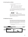
5.5 ARQ Mode Operation
In ARQ operation one station (information sending station) sends
data to another in block by block, then listens the acknowledge
signal between blocks from the information receiving station which
requests either the next block or retransmission of the last block if
there is error. The request may be repeated up to 32 times, until the
complete block is received free of error.
1. Press function key [F3] followed by the [1] key. The Call Station menu appears.
1:File 2:Edit 3:Operate 4:Window 5:Station 6:System 7:WRU 8:HR 9:Over 10:Break
1996-11-15 14:41:09(JST)
Caps
Station Name
: CHOUSHI-8M
Call Station Comm Mode :AQW
Frequency (T/R) :
8765.00 / 8965.00(kHz)
Comm Status
:
Connect
Send
Lock Error Station
Mark Space
Station List
Setup
Sending Volume : 100(%)
ARQ Error : 0
ARQ Time : 0(sec)
Station : ABC-4M
ABC-4M
ID Code : 45678
ABC-6M
Mode
: ARQ FEC
ABC-12M
CH/Table : Channel Scantable
ABC-8M
Num/Table:
FURUNO
Figure 5-7 Call Station menu
5-5
2. Select a station. (Station must be registered for the ARQ mode).
Press the [Enter] key. The message "Calling Station" appears.
If the message "Station calling suspended. Check radio and
interconnections. Press any key to escape." appears, check both
radio's power and interconnections between the radio and the
DP-6.
3. When an acknowledge signal is detected, "Connect" appears
in inverse video on the communication status display (see next
page).
Note: If signal conditions are poor, connection may take a
while. If the line could not be connected in one minute, calling
stops and "Calling failed" appears. Try step 2 again one minute
later. Should signal conditions worsen during message
transmission, "Error" appears in inverse video and 30 seconds
later the line is disconnected.
4. Transmit message by one of the following methods;
Send a file from a floppy disk
a) Press function key [F7] (WRU) to receive the answerback
code of the other station. Verify that the code from the station called is correct.
b) Press function key [F8] (HR) to transmit your own identity
(answerback code).
c) Press function key [F3] and then the [3] key to display the
Send screen. Select file to send and press the [Enter] key.
Send appears in inverse video while the file is being transmitted.
Send File
Filename
Size
Data & Time
<Parent Directory>
96-11-15 12:24
00FOX
.MES
95 96-11-15 08:07
ASCII
.TXT
613 96-11-15 16:15
BEEP
.EXE
28854 96-11-15 10:36
DPX
.AUT
1830 96-11-15 10:02
DPX
.BAT
349 96-11-15 13:54
DPX
.BSC
28000 96-11-15 17:11
DPX
.CNL
1000 96-11-15 10:02
29 Files exist
247271424 bytes free
To select:ENTER
To view:SPACE
To quit:ESC
Figure 5-8 Send file screen
Sending volume (percentage of message transmitted, counts
upward as the message is being transmitted), ARQ error count
and ARQ transmission time appear on the display.
5-6
1:File 2:Edit 3:Operate 4:Window 5:Station 6:System 7:WRU 8:HR 9:Over 10:Break
1996-11-15 14:28 (JST)
Caps
Station Name
: CHOUSHI-8M
Frequency (T/R) :
8765.00 / 8965.00(kHz) Comm Mode :ARQ
Comm Status
: Connect Send Lock Error
Sending Volume : 100(%)
ARQ Error : 0
ARQ Time : 0(sec)
Figure 5-9 Communication status display
Type a message from keyboard
After exchanging answerback code by the function key [F7]
(WRU) and [F8] (HR), type your message directly from the
keyboard.
5. To change direction of traffic, press either function key [F9]
(OVER), or [+] and [?]. Then, the other station becomes the
information sending station, your station the information receiving station.
6. Receive a message from the sending station, if any.
7. After completion of communication, press function key [F7]
(WRU) key to receive the answerback code of the other station
and then press function key [F8] (HR) key to transmit your
own answerback code.
8. Press function key [F10] (BREAK) to disconnect the line.
5.6 FEC Mode Operation
The FEC method of error correction is used when there is more
than one receiving station, and no replies are required by the other
station. Each message is sent twice, the characters of the first message interleaved with those of the second. The receiving station
thus has two chances to receive each character correctly. If both
characters are in error, an asterisk (*) is printed.
1. Press function key [F3].
2. Press the [1] key to display the Call Station menu.
You can select scan group by scan table.
3. Select a station which is registered for the FEC mode. Press
the [Enter] key. CONNECT lights in inverse video.
4. Transmit message from a floppy disk as follows.
Press function key [F3] and the [2] key to open the Send screen.
Select file to send and press the [Enter] key.
5. After the message is transmitted, press function key [F10]
(BREAK) to disconnect the line.
5-7
5.7 Communication Example
This section shows how to register your station with a coast station
(Singapore), in order to connect with a land line and send messages to other stations.
Contact the coast station following the procedure on page 5-3. Then,
register your station's name, call sign, answerback code and selcall
number and AAIC (Accounting Authority Identification Code) with
the coast station.
You can call the Singapore coast station on ITU channels 809, 821
or 1201 (other channels may also be used). Use communication
mode ARQ. The Singapore coast station ID no. is 4620.
Registration procedure
1. Call Singapore coast station following the procedure on page
5-3.
2. Singapore requests your AAIC.
3. Type your AAIC.
4. Singapore asks for your callsign. Send your station's name,
callsign, answerback code and selcall number.
5. Singapore sends time required to register your station.
6. Transmit end code.
9VG SERADIO RS
12345 FURUNO X
54321 ABCDE J
Exchange answerback codes
9VG SERADIO RS
MOM
F
UGOX DE 9VG RGR GA X X PSE SUPPLY YOUR AAIC HW +?
Singapore requests your AAIC.
OPR +
Call operator.
AAIC AA01 +?
RGR PSE GIVE YOUR SHIP NAME CALLSGI CALLSIGN HW +?
I INTRODUCE MY INFO LATER
Singapore requests your station's name and callsign.
PLS AGAIN
AAAAAA
CS- 1111
Enter your stations name, callsign, answerback,
ANSWERBACK CODE- ccccc cccc c
AAIC- 9999
code and selcall number.
SELCALL- 56789
OK HW +?
PSE BE SURE W ICH AAIC CFM PSE HW +?
bb01 SO + +?
RGR PSE OFF TX X HERE EEE CALL BACK 2MINS TIME X HERE WILL
INPUT YOUR DATA
Time required to reigister your station
CU BI HW +?
OK TKS BI BI
5-8
Transmitting message directly (DIRTLX)
The procedure which follows shows how to transmit a Telex message directly to a station.
1. Execute "Calling a Station" on page 5-3.
2. After GA+ and DIRTLX appear on your display, type Receiving station's Telex number.
3. Singapore coast station sends its Telex number. Type receiving
station's answerback code.
4. Type MSG+?
5. Type your message.
6. Type WRU. Receiving station and your station mutually exchange answerback codes automatically.
7. Type KKKK (end code) at end of message. Your answerback
code, receiving station's Telex number and communication time
appear on your display.
8. Receiving station sends GA+?.
To send another message by DIRTLX, start at step 2. To finish,
type BRK+
9VG SERADIO RS 55908 UGOX X
GA +?
DIRTLX07205644325 = +
TRY AGAIN OR USE 'OPR'
GA +?
DIRTLEX07205644325 +
MOM07205644325 +
5644325FURUNO J
MSG +?
12345 FURUNO J
Exchange answerback codes
After GA+ appears type Receiving station's
Telex number.
If there is a mistake in the number coast station
asks you to reenter number.
Receiving station's Telex no.
Type receiving station's answerback code.
Prepare to send message.
TO FURUNO
THIS IS A TEST MESSAGE FROM ab cdefgh ijkl IN KOBE.
WRU
5644325FURUNO J +?
54321 ABCD N
KKKK
55908 UGOX X
9VG SERADIO RS
TIME: 29. 5. 96 7:49
SHIP: 555908 UGOX X
SUBSCR:07205644325 +
DURATION:1.4MIN
GA +?
BRK +
Type message.
End code. Your ship's answerback code, receiving station's
Telex no. and communication time appear.
BRK + disconnects the communication line.
To send another message type DIRTLX instead of BRK +.
5-9
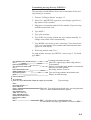
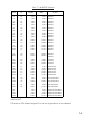
Table of Abbreviations
Abbreviation
Question
Answer or Advice
QRA
What is the name your station?
The name of my station is · · · · .
QRC
By what private enterprise are the
accounts for charges for your station
settled?
The accounts for my station are settled
by the private enterprise · · · · .
QRU
Have you any thing for me?
I have nothing for you.
QRV
Are you ready?
I am ready.
QRX
When will you call me again?
I will call you again at · · · · hours [on
· · · · kHz].
QSJ
What is the charge to be collected to · The charge to be collected to · · · ·
· · · including your internal charge?
including my internal charge is · · · ·
frans · · · · .
QSL
Can you acknowledge receipt?
I can acknowledge receipt.
QSX
Will you listen to · · · · [call sign] on
· · · · kHz?
I am listening to · · · · [call sign] on
· · · · kHz.
Q TA
Shall I cancel message number · · · · ? Cancel message number · · · ·
QTC
How many messages have you to
send?
I have · · · · message for you.
Q TU
What are the hours your station is
open?
My station is open from · · · · to · · · ·
hours.
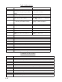
Abbreviation
Definition
BK
Signal used to interrupt a transmission progress.
CFM
Confirm
DE
"From · · · · "
K
Invitation to transmit.
NIL
I have nothing to send to you.
NW
Now
PSE
Please
R
Received
REF
Reference to · · · · .
SVC
Prefix indicating a service telegram.
Command an Abbreviation
Command
Function
TGM+
To indicate that the following message is a radiotelegram.
MSG+
To indicate that the ship station needs to be connected immediately any message held.
OPR+
Call operator.
URG+
Safety, urgency and distress message.
MED+
Request medical advice.
TEST+
Request coast station to send a test message for checking the ship station.
BRK+
To clear the connection with the coast station.
Abbreviation
GA+
I am ready. Transmit your command.
MOM
Wait a moment.
MSG+
Request pending messages from the shore.
KKKK or NNNN Terminate a message.
5-10
5.8 Timer Operation
A built-in timer permits automatic transmission and reception of
telex messages.
Enabling Timer Operation
1. Press function key [F3] to display the Operate menu.
2. Press the [7] key to display the Timer Operation List.
3. Select the operation (name) you wish to execute. Press the [Enter] key. An asterisk appears beside the operation selected and
"T. Op" appears in inverse video on the communication status
display. If a file from a floppy disk is to be sent, be sure the
floppy disk containing the file is inserted in the drive.
Timer Operation List
*1
2
3
OP4
OP5
Figure 5-10 Timer operation list
4. Select another operation (name) if desired.
5. Press the [Esc] key.
When the predetermined time comes, the DP-6 automatically sends
or receives messages. The results of timer operation are displayed
as either OK or NG (No Good) on the Timer Operation List.
Timer Operation List
*1
2
*3
*OP4
*OP5
OK
OK
OK
NG
Figure 5-11 Timer operation list
Stopping Timer Operation
1. Press function key [F3].
2. Press the [7] key.
3. Select the operation (name) which has asterisk attached to it
and then press the [Enter] key. Remove all asterisks to cancel
all timer programs.
5-11
5.9 Scanning
Radio equipment scans a group of operator-selected frequencies
(channels), and stops scanning when an incoming signal is received.
1. Press function key [F3] and then the [5] key. The Scanning
Group
List
appears
on
the
screen.
You can confirm the scan channel by [↑] key or [↓] key while
pressing the [Shift] key.
Scanning Group List
*1
2
*3
Figure 5-12 Scanning group list
2. Select a scan group and press the [Enter] key.
3. The scanning starts and the indication "Scan" appears in inverse video on the communication status display. (The name
of the scan group appears at the "Station Name".)
1:File 2:Edit 3:Operate 4:Window 5:Station 6:System 7:WRU 8:HR 9:Over 10:Break
1996-11-15 02:01 (JST)
Station Name
: SAITO-1
Print Scan T.Op HT Scra
Frequency (T/R) : 8344.00 / 8705.00(kHz) Comm Mode : CW
Comm Status
: Connect Send Lock Error
Sending Volume : 100(%)
ARQ Error : 0
ARQ Time : 0(sec)
Figure 5-13 Communication status display
4. To stop scanning, press function key [F3] and then the [5] key.
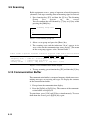
5.10 Communication Buffer
The communication buffer is a temporal memory which stores transmitting messages or receiving messages. To display the contents
of the comunication buffer;
1. Escape from the communication display.
2. Press the [PgDn] or [PgUp] key. The contens of the communication buffer are displayed.
To print them, press [Ctrl] and [P] keys simultaneously. To erase
them from the screen, press [PgDn] key again.
5-12
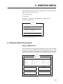
6. WINDOW MENU
The Window menu allows you to display one of the following together with the current screen:
1) Navigation data
2) Calendar
3) Remote controller screen (Remote A or Remote B)
4) Distress frequencies
Window
1: Display NMEA Data
2: Calendar
3: Remote A (TX/RX)
4: Remote B (DSC)
5: Distress Frequency Table
Figure 6-1 Window menu
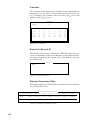
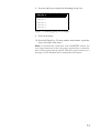
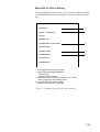
6.1 Window Menu Description
Display NMEA Data
With connection of a navaid and appropriate sensors which output
nav data in IEC1162 (NMEA0183) format, position, speed, water
temperature, depth and heading can be displayed. Press function
key [F4] and the [1] key. Asterisks appear where there is no data.
NMEA
Lat/Lon
Latitude
LA
LC
NNSS
DECCA
GPS
**°**.*** N
**°**.*** N
**°**.*** N
**°**.*** N
**°**.*** N
Temperature
*.* ( °C )
Ship's Speed
*.* (Knot)
Longitude
***°**.***
***°**.***
***°**.***
***°**.***
***°**.***
E
E
E
E
E
Depth
*.* ( Ft )
Heading
*.* ( °
)
Figure 6-2 NMEA data display
6-1
Calendar
The Calendar menu displays the calendar of any combination of
month and year you desire. Press function key [F4] and the [2]
key. To change year or month, select it by the [ ]/[ ] keys and
change by the [ ]/[ ] keys.
Calendar
1996
11
Year :
Month :
Sun
( 3)
(10)
(17)
(24)
Mon
Tue
Wed
Thu
4
11
18
25
5
12
19
26
6
13
20
27
7
14
21
28
Fri
1
8
15
22
29
Sat
2
9
16
23
30
Figure 6-3 Calendar
Remote A, Remote B
This menu permits remote control of a FURUNO transceiver, receiver or transmitter connected to Remote A or Remote B terminal. Press function key [F4] and the [3] key (Remote A) or the [4]
key (Remote B).
Remote
MIF>
Figure 6-4 Remote screen
Distress Frequency Table
This menu displays all current distress frequencies. Press function
key [F4] and the [5] key.
Distress Frequencies
Telepone (kHz) : 2182.0 4125.0 6215.0 8291.0
12290.0
16420.0
NBDP
(kHz) : 2174.5
4177.5
6268.0
8376.5
12520.0
16695.0
DSC
(kHz) : 2187.5
4207.5
6312.0
8414.5
12577.0
16804.5
Figure 6-5 Distress frequency table
6-2
7. MARITEX OPERATION
This chapter provides an overview to the MARITEX system. For
detailed information, consult your MARITEX Traffic Manual.
7.1 What is MARITEX?
MARITEX, an acronym meaning MARItime TEleX, is a worldwide, round-the-clock, fully automatic and computerized network
for maritime radiotelex. The MARITEX system is operated jointly
by the Telecom Administrations of Denmark, Finland, Iceland,
Norway, and Sweden. The system consists of the Central Computer System in Gothenburg, Sweden, run with two high technology computers, and sub-stations in Scandinavia, Panama, Manila,
and Argentina. The Central System does all the message switching
and co-ordinates the sub-station resources.
INTERNATIONAL
TELEX NETWORK
REMOTE-CONTROLLED
RADIO CIRCUITS
STORE-ANDFORWARD
PARTICIPATING
SHIPS
SUB-STATION
PANAMA
DIRECT
DIALING
MULTIADDRESS
INTERNATIONAL
TELEPHONE
NETWORK
MARITEX
CENTRAL
SYSTEM
SYSTEM
CONTROL
SUB-STATION
SCANDINAVIA
SUB-STATION
MANILA
SEMI-FAX
SUB-STATION
ARGENTINA
Figure 7-1 MARITEX system and services
7-1
MARITEX Services
MARITEX provides four main services to MARITEX subscribers:
• Store-and-forward telex
• Direct dialing
• Multi address
• Semi-fax
Note: MARITEX provides both shore-to-ship and ship-to-shore
services. This manual, however, describes only the ship-to-shore
communication procedures.
7.2 Preparations for Transmission
To transmit a message in the MARITEX system, you will need to
register three items:
• Answerback code
• Scan groups
• Station names
Registering Answerback Code
MARITEX assigns a Telex number to all MARITEX subscribers.
This number functions as an answerback code. An answerback code
contains the following:
OOOOO SHIP X
OOOOO: MARITEX-assigned five-digit Telex code
SHIP:
Ship name
X:
For shipboard station, normally X is entered.
The procedure for registering answerback code is the same as which
appears on page 3-1. If an answerback code was registered before
the commissioning of the MARITEX station a new answerback
code must be entered. To enter new answerback code, contact
FURUNO or authorized FURUNO agent or dealer.
7-2
Registering Scan Groups
The Central System emits a free-signal to indicate a MARITEX
radio channel is in idle condition and available for ship-to-shore
calls. The free-signal is detected and recognized by the shipboard
equipment as a permission to start the transmission. Then, the shipboard operator initiates a call.
You can scan search for the free-signal automatically by registering MARITEX radio channels in scan group(s). The procedure for
registering scan groups for MARITEX use is the same as that which
appears on page 3-7.
1. Press function key [F5] to display the Station menu.
2. Press the [3] key to select Scan Entry. The screen should look
something like Figure 7-2.
Scan Entry
Scanning Group List
Create
Change
Scanning Set Up
Group Name
Ch Dwell Time
Mode
Auto Search
No
1
2
3
4
5
▼ 6
Channel
:
: 4.5 sec (2.7-4.5 sec)
: AUTO ARQ FEC
: OFF ON
Rx Freq
Tx Freq
Pass/Scan
Pass/Scan
Pass/Scan
Pass/Scan
Pass/Scan
Pass/Scan
Pass/Scan
Figure 7-2 Scan entry screen
3. If Create is not underlined, press [ ], [ ] and the [Enter] key
to underline it.
4. Group Name appears in inverse video, meaning you can enter
scan group name. Enter scan group name; for example,
MARITEX-A.
5. Press the [ ] key to advance the cursor to Ch Dwell Time. The
dwell times is the time in seconds the receiver waits on each
channel before it selects the next channel. The default setting
is 2.7 seconds. Change the setting if necessary.
7-3
6. Press the [ ] key to advance the cursor to Mode. Select the
communication mode, AUTO, ARQ or FEC.
7. Press the [ ] key to advance the cursor to Auto Search. Turn
Auto Search ON or OFF;
Auto Search ON: Radio stops scanning when it finds the strongest (S/N ratio) free-signal frequency. Use it where signal propagation in poor.
Auto Search OFF: Scanning starts and stops with the firstreceived free-signal frequency. Normally, use this position.
8. Press [ ] to place the cursor on the No. 1 line. Enter channel or
user channel. See the table on the next page for MARITEX
radio channel information. Then, press the [ ] key to select
"Scan".
9. Press [ ] to advance the cursor to the No. 2 line. Enter channel
number. Repeat this procedure for other channels, up to 20.
10. Press the [Enter] key.
11. Press the [Enter] key again to register scan group.
Scan Entry
Scanning Group List
Create
Change
MARITEX-A
Scanning Set Up
Group Name
Ch Dwell Time
Mode
Auto Search
No
1
2
3
4
5
▼ 6
Channel
1
2
3
4
5
6
:
:
:
:
MARITEX-A
4.5 sec (2.7-4.5 sec)
AUTO ARQ FEC
OFF ON
Rx Freq
Tx Freq
Pass/Scan
Pass/Scan
4268.60
4203.50
Pass/Scan
6460.00
6302.00
8398.50
Pass/Scan
8556.00
12563.50 Pass/Scan
12818.00
16790.50 Pass/Scan
17024.00
22352.00 Pass/Scan
22607.00
Figure 7-3 Scan entry screen
To enter another scan group, select Create and then press the [Enter] key. Repeat steps 3 – 9.
7-4
Table 7-1 MARITEX Channel
ITU
Channel
MARITEX
No.
UP
UP
UP
A7
B7
D7
2423.5
2716.0
1905.0
3267.5 SWEDEN
2477.0 SWEDEN
2222.0 SWEDEN
UP
4009
4014
A1
B1
C1
4268.6
4214.5
4216.5
4203.5 SWEDEN
4176.5 SWEDEN
4179.0 SWEDEN
UP
6001
6019
A2
B2
C2
6460.0
6314.5
6323.0
6302.0 SWEDEN
6263.0 SWEDEN
6272.0 SWEDEN
UP
8007
8024
A3
B3
C3
8556.0
8419.5
8428.0
8398.5 SWEDEN
8379.5 SWEDEN
8388.0 SWEDEN
UP
12006
12024
A4
B4
C4
12818.0
12582.0
12591.0
12563.5 SWEDEN
12479.5 SWEDEN
12488.5 SWEDEN
UP
16014
16064
16057
A5
B5
C5
C7
17024.0
16813.5
16838.0
16834.5
16790.5
16690.0
16715.0
16711.5
UP
22007
22032
A6
B6
C6
22607.3
22379.5
22392.0
22352.0 SWEDEN
22287.5 SWEDEN
22300.0 SWEDEN
8017
12008
16033
22031
D3
D4
D5
D6
8424.5
12583.0
16822.5
22391.5
8384.5
12480.5
16699.5
22299.5
PANAMA
PANAMA
PANAMA
PANAMA
4006
8040
12050
16188
22040
16164
F1
F3
F4
F5
F6
F7
4213.0
8436.0
12604.0
16900.0
22396.0
16888.0
4175.0
8396.0
12501.5
16782.0
22304.0
16770.0
ARGENTINA
ARGENTINA
ARGENTINA
ARGENTINA
ARGENTINA
ARGENTINA
6001
8028
12028
16028
G3
G4
G5
G6
6314.5
8430.0
12593.0
16820.0
6263.0
8390.0
12490.5
16697.0
SAN FRANCISCO
SAN FRANCISCO
SAN FRANCISCO
SAN FRANCISCO
8027
12067
G1
G2
8429.5
12612.5
8389.5 NEW ORLEANS
12510.0 NEW ORLEANS
4219.0
6329.0
8431.0
12622.5
16854.0
4181.5
6283.0
8391.0
12520.5
16731.0
4019
6031
8030
12088
16096
Coast Station
TX (kHz)
Ship Station Tx
(kHz)
Location
SWEDEN
SWEDEN
SWEDEN
SWEDEN
CHINA/GUANGZHOU
CHINA/GUANGZHOU
CHINA/GUANGZHOU
CHINA/GUANGZHOU
CHINA/GUANGZHOU
Valid on 1997.
UP means no ITU channel assigned. You can use register these as user channels.
7-5
Registering Stations
The next step is to enter station name. The procedure is the same
as the procedure shown on page 3-3. The station list provides abbreviated dialing with storage for up to 50 stations.
1. Press function key [F5] and the [1] key. The Station Entry screen
appears.
Station Entry
Station List
Create
Change
Station Set Up
Station :
ID Code :
Mode
: ARQ FEC DIRC
CH/Table : Channel ScanTable
Num/Table:
Figure 7-4 Station entry screen
2. If Create is not underlined, press [ ], [ ] and the [Enter] key
to underline it.
3. The cursor is on the Station line. Enter station name, using up
to 20 characters.
4. Press the [ ] key to go to the ID Code line. Enter station ID
code; the coast station selective call number common to all
stations is 2950.
5. Press the [ ] key to go to the Mode line. The MARITEX system uses the ARQ mode.
6. Select ScanTable on the CH/Table line.
7. Press [ ] to go to Num/Table.
7-6
8. Press the [ ] key to display the Scanning Group List.
Scanning Group List
MARITEX-A
MARITEX-B
MARITEX-C
MARITEX-D
MARITEX-E
MARITEX-F
Figure 7-5 Scanning group list (example)
9. Select scan group.
10. Press the [Enter] key. To enter another station name, repeat the
above procedure from step 2.
Note: To establish the connection with a MARITEX station, the
receiving frequencies in the scan group registered are scanned to
detect a free signal from the station. If the free signal is detected, a
message will be automatically transmitted to the station.
7-7
7.3 Preparing Programs for Automatic Message
Transmission
This section shows you how to prepare the programs necessary for
automatic message transmission. The programs, which you can
save to a floppy disk for future use, enable unattended automatic
transmission.
The program for automatic transmission is called a macrofile. You
will need several types of macrofiles depending on the MARITEX
service to be utilized.
Commands
The tables which follow describe the commands for automatic transmission.
Table 7-2 describes the commands processed by the DP-6.
Table 7-2 Commands processed by the DP-6
Command
(prefixed with @)
Parameter
Content
CALL
S: Station Name
I: ID
Calling station name and ID on assigned
parameter
FREE (support
command for CALL)
Two digits
0?99 min.
Free-signal searching time according to
assigned parameter (default setting: 10 min.)
RETRY (support
command for CALL)
Two digits
0?99 min.
Calling according to assigned parameter
(default setting: 10 min.)
CASE
Text
For receving a message (designanted by
parameter) transmitted by coast station
TIMEOUT (support
command for CASE)
Two digits
0?99 min.
Time alloted for reception of message by
CASE command
SEND
Text
Text transmitted according to assigned
parameters
B:file name
Send a file from floppy disk
WRU
HR
OVER
BREAK
None
Function keys [F7] ? [F10]
DISPLAY
Text
Text of message appears
INPUT
None
Waiting for keyboard input
Transmit keyboard input message
7-8
After reception of GA+?, enter appropriate short-code command.
Table 7-3 shows the commands processed by MARITEX stations.
Table 7-3 MARITEX short-code commands
Command
Use
TLX ..... +
DIRTLX ..... +
MULTI ..... +
FAX ..... +
MSG+
NNNN+
BRK+
Store-and-forward Telex
Direct dialing Telex
Multi-address
Semi-fax
Request pending messages from shore
Terminate message
Clear the radio circuit
Other MARITEX short-code commands are as below.
Table 7-4 Other MARITEX short-code commands
Command
Use
POS+
URG+
MED+
LTR+
TST+
MRK+
Transmission of ship position reports
Safety, urgency and distress messages
Request medical advice
For MARITEX letters mailed from the Operations Center to destinations worldwide
Request to MARITEX to send a test message consisting of all Telex characters
Request to MARITEX to send a continuous mark tone for one minute
Note: For other supporting and facility commands, consult the
MARITEX Traffic Manual.
7-9
Store-and-Forward Telex
The following is the sequence of events in transmission of Telex
message in MARITEX.
1. Shipboard station sends message to MARITEX coast station.
2. MARITEX coast station stores message in memory buffer.
3. Shipboard station and MARITEX coast station clear the radio
circuit.
4. MARITEX station sends message to subscriber designated.
No. Procedure
1
Call MARITEX.
2
Transmit WRU signal.
3
Remarks
CONNECT appears
in inverse video
(and bell sounds).
Free-signal found;
radio circuit ready.
MARITEX X
26 X X X SHIP X
GA+?
Initial identity
exchange between
coast station and
shipboard station
MSG+?
Request to start
message transmission
Key in subscriber's Telex number.
Example: (Hong Kong) 12345
TLX80212345+
4
Transmit file.
5
When transmission is completed,
type NNNN.
6
Transmit BREAK command to
clear radio circuit.
7-10
Display
Message transmission
26 X X X SHIP X
MARITEX S
DURATION
DATE
GA+?
Transmit your
answerback code.
Receive MARITEX
station's answerback
code. Tx time and date
appear on DP-6.
Preparing a macrofile for store-and-forward Telex
You will need a macrofile to enable automatic message transmission on store-and-forward Telex. After preparing it, save it to the
hard disk or a floppy disk for future use.
1. Press function key [F1] to display the File menu.
2. Press the [1] key.
3. Prepare macrofile.
The figure below shows the minimum information required to send
a store-and-forward Telex message in MARITEX.
< [1] UNTITLED1 >
@FREE 10
1
@CALL S: MARITEX
2
@WRU
@CASE GA+?
@SEND TLX80212345+
3
@CASE MSG+?
@SEND B:ABC
4
@SEND NNNN
5
@CASE GA+?
@SEND BRK+
1 Free-signal search time (10 minutes
2 Station name (Example: MARITEX)
Who are you?
Station identity exchange
3 Subscriber's Telex number (in example, 802 is country
code of Hong Kong) for store-and-forward Telex
4 Location and name of file message
5 Request for termination of message
Figure 7-6 Example macrofile for store-and-forward Telex
4. Press function key [F1] to display the File menu.
7-11
5. Press the [5] key. The Save prompt appears on the display.
close Text
Saving File Name
Yes
No
(Untitled 1)
Figure 7-7 Save prompt
6. Press the [Enter] key and enter a file name as follows.
OOOOOOOO.MCR
↑
↑
File Name
Extension Name
(max. 8 characters)
7. Press the [Enter] key.
7-12
Macrofile for Direct Dialing
The direct dialing features allows you to contact a land subscriber
via MARITEX. Below is an example of a macrofile for direct dialing
@FREE 15
1
@CALL S: MARITEX
2
@WRU
@CASE GA+?
@SEND DIRTLX725644325+
3
@CASE MSG+?
@SEND B:ABC
4
@SEND NNNN
5
@CASE GA+?
@SEND BRK+
1 Free-signal search time (15 minutes
2 Station name (Example: MARITEX)
Who are you?
Station identity exchange
3 Subscriber's Telex number (in example, 72 is country
code of JAPAN) for direct dialing mode
4 Location and name of file message
5 Request for termination of message
Figure 7-8 Example macrofile for direct dialing
7-13
Procedure for direct dialing
No. Procedure
1
Call MARITEX.
2
Transmit WRU signal.
3
Remarks
CONNECT appears
in inverse video (and
bell sounds).
Free-signal found;
radio circuit ready.
MARITEX X
26 X X X SHIP X
GA+?
Initial identity
exchange between
coast station and
shipboard station
Key in subscriber's Telex number.
Example: (Japan) 725644325
DIRTLX725644325+
4
Transmit prepared file or input
message manually through
keyboard.
5
When transmission is completed,
type NNNN.
6
Transmit BREAK command to
clear radio circuit.
7-14
Display
12:20
MOM
5644325 FURUNO J
MSG+?
Request to start
message transmission
Message transmission
26 X X X SHIP X
5644325 FURUNO J
DURATION
DATE
GA+?
Transmit your
answerback code.
Receive MARITEX
station's answerback
code. Tx time and
date appear on DP-6.
Macrofile for Multi Address
The figure which follows shows an example of a macrofile for
multi address use.
@FREE 15
1
@CALL S: MARITEX
2
@WRU
@CASE GA+?
@SEND MULTI+
3
@CASE num+?
@SEND 725644325
@SEND 80255785
4
@SEND 5412345
@SEND 42124567
@CASE MSG+?
@SEND B:ABC
5
@SEND NNNN
@CASE GA+?
@SEND BRK+
Figure 7-9 Example of macrofile for use in multi address
7-15
Macrofile for Semi-fax
In the Semi-fax option, MARITEX converts ship-to-shore direction telex message to facsimile and retransmits it via the telephone
network.
The figure below shows an example of a macrofile for Semi-fax.
The macrofile for Semi-fax is the same as the macrofile for storeand-forward and direct dialing except for the FAX command.
@FREE 15
1
@CALL S: MARITEX
2
@WRU
@CASE GA+?
@SEND FAX802123456+
3
@CASE MSG+?
@SEND B:ABC
4
@SEND NNNN
5
@CASE GA+?
@SEND BRK+
Figure 7-10 Example of macrofile for semi-fax
7-16
7.4 Transmitting in MARITEX System
This section describes how to transmit a Telex message in
MARITEX.
Basic Procedure
1. Register answerback code (Telex number assigned by
MARITEX).
2. Register MARITEX frequency and channel to scan group.
3. Register station name including scan group name.
4. Retrieve appropriate macrofile. Include station name and message file name. Type message and save file to memory.
5. Open macro operation menu and select macrofile. (See next
page for details.) Your message will be transmitted automatically. Below is the sequence of automatic message transmission in MARITEX.
1) Search for free-signal
2) Call MARITEX station on MARITEX radio channel.
3) After connection is established, identity exchange
4) Transmission of service category and subscriber’s address
5) Transmission of message
6) Transmission of termination of message signal
7) Identity exchange
8) Clearing of radio circuit
7-17
Actual Transmission
1. Press function key [F3] to display the Operate menu.
Operate
1: Call Station
2: Macro Operation
3: File to Send
4: Cancel Sending
5: Scan (Start/Stop)
6: Manual Reception
7: Timer Operation
8: High Tension ON
9: Manual Calling
0: Set Frequency
Figure 7-11 Operate menu
2. Press the [2] key. The Call Macro screen appears.
Call Macro
Filename
Size
MARITEX1.MCR
MARITEX2.MCR
95
95
Date & Time
1996-12-13
1996-12-11
11:20
12:20
Name
Date
File Count: 2
Memory:2K Used
98K Available
Figure 7-12 Call macro screen
3. Select desired macrofile and press the [Enter] key.
4. Press the [Enter] key to confirm the macrofile selected. The
Wait for Free Signal indication appears. Your message will be
transmitted automatically.
7-18
8. MAINTENANCE AND
TROUBLESHOOTING
WARNING
Do not work inside the
equipment unless totally
familiar with electrical
circuits.
Hazardous voltage which can
cause electrical shock, burn or
serious injury exists inside the
equipment.
8.1 Maintenance
Regular maintenance is important for good performance. A regular maintenance program should be established and should at least
include the following:
Cleaning the Equipment
Wipe of accumulated dust from the equipment with a soft cloth.
An anti-static cleaner may be used to clean the screen of the terminal unit. Do not use commercial cleaners to clean the equipment.
They can remove paint and markings.
Connectors and Earth Connection
Periodically check the connectors for proper seating and the earth
connection for rust. Remove rust to maintain a good ground system.
Floppy Disk Drive
Clean the floppy disk drive head regularly to prevent erasure of
information stored on disks.
8-1
8.2 Simple Troubleshooting
Power Supply
If the power cannot be applied (power lamp on the main unit does
not light):
• Check for loosened power cable connector on the rear or bottom of units. Check that the ship's mains main switch is turned
on. Confirm that power is present at the connector (pin #1:(+),
pin #2: (-)).
Unit
Input Voltage
Main unit
24 VDC
Terminal unit
24 VDC
• Check if the breaker on the rear panel of the terminal unit has
tripped. If it has tripped, push it in to reset the equipment.
8.3 Diagnostic Tests
Self Test
1. Press function key [F6] to display the System menu.
Setup
System
Lock
Change
Slave Delay
BK Timing PreTone
PostTone
Mute Timing PreBK
PostBK
5
10
0
0
0
Modem Output Level
0 dBm (-30 - +10 dBm)
MIF Tune
Freeze
AGC
Emission
OFF
OFF
OFF
OFF
O
O
O
O
TX/RX MSG Save
Edit Before sending
OFF
OFF
O N
O N
Time System
Time & Date
Display Mode
Self Test
OFF UTC SMT JST
1997/1/1/12:34:56
Normal Reverse
msec
msec
msec
msec
msec
Figure 8-1 System menu
2. Select Change on the Setup line.
3. Select Self Test.
8-2
Default
(0- 50
(0-100
(0- 20
(0- 20
(0- 20
msec)
msec)
msec)
msec)
msec)
N
N
N
N
4. Press the [Enter] key. The results of the self test are displayed a
short time later.
Self Test
Terminal Unit Test :
Main Unit Test
:
Modem Unit Test
:
Radio Unit Test
:
DSC Unit Test
:
Printer Unit Test*2:
ver. 1.20
ver. 1.17
ver. 1.18
ID xxxx*1
ID xxxx*1
Printer not Ready
:OK
:OK
:OK
:OK
:OK
:NG
*1: Actual ID numbers appears.
*2: OK replaces NG when printer is turned on and normal.
Figure 8-2 Self test results
If NG appears for any unit checked, try the self test again. If it
appears again, call for service.
Tone Test
1. Select Self Test on the System menu.
2. While pressing and holding down the [Shift] key, press the [ ]
key.
Tone Test
1:
2:
3:
4:
5:
6:
Tone
Tone
Tone
Tone
Tone
Tone
Test
Test
Test
Test
Test
Test
1
2
3
4
5
6
(All Char)
(Fox)
(Beta)
(Mark)
(Space)
(BY)
Figure 8-3 Tone test
3. Select test and press the [Enter] key. You may stop a test at
anytime by pressing the [Enter] key.
Tone test 1 (All characters)
This test (continuously) checks for proper transmission of all figures, letters and codes. To conduct the test, call a station in the
ARQ or FEC modes. Execute the test, confirming that all characters are transmitted correctly. "Now testing Tone Test 1" appears
during the testing. Since the test is conducted continuously, you
may press [Esc] twice and [F10] key to stop the test and return to
the tone test menu.
8-3
1:File 2:Edit 3:Operate 4:Window 5:Station 6:System 7:WRU 8:HR 9:Over 10:Break
System
1996-11-15
13:26:45.45
Caps Eng
Station Name
:
Setup
Lock Change
Default
Frequency (T/R) :
/
(kHz) Comm Mode : Auto
Comm Status
: Connect Send Lock Error Mark Space
Now Testing Tone Test 1 (All Char).
ABCDEFGHIJKLMNOPQRSTUVWXYZ1234567890-?:().,’=/+abcdefghijklmnopqrstuv
wxyz
ABCDEFGHIJKLMNOPQRSTUVWXYZ1234567890-?:().,’=/+abcdefghijklmnopqrstuv
wxyz
ABCDEFGHIJKLMNOPQRSTUVWXYZ
Figure 8-4 All characters test screen
Tone test 2 (Fox)
This test (continuously) checks for proper transmission of the test
message THE QUICK BROWN FOX JUMPS OVER THE LAZY
DOG 0123456789. In order to conduct the test call a station over
the ARQ or FEC mode.
Tone test 3 (Beta)
You may check for proper transmission of the idle signal β. Call
up a station using the ARQ mode.
Tone test 4 (Mark)
This test outputs the mark signal through the LINE OUT terminal,
where a frequency counter may be connected, to confirm its frequency (1615 Hz).
Tone test 5 (Space)
Tone test 5 verifies the space signal frequency (1785 Hz).
Tone test 6 (BY)
This test verifies the frequency of the space B (1785 Hz) and mark
Y (1615 Hz), using a spectrum analyzer.
8-4
No.
4001
4002
4003
4004
4005
4006
4007
4008
4009
4010
4011
4012
4013
4014
4015
4016
4017
4018
4019
4020
4021
4022
4023
4024
4025
4026
4027
4028
4029
4030
4031
4032
4033
4 MHz BAND
TX
4172.5
4173.0
4173.5
4174.0
4174.5
4175.0
4175.5
4176.0
4176.5
4177.0
4177.5
4178.0
4178.5
4179.0
4179.5
4180.0
4180.5
4181.0
4181.5
4202.5
4203.0
4203.5
4204.0
4204.5
4205.0
4205.5
4206.0
4206.5
4207.0
4207.5
4208.0
4208.5
4209.0
RX
4210.5
4211.0
4211.5
4212.0
4212.5
4213.0
4213.5
4214.0
4214.5
4215.0
4177.5
4215.5
4216.0
4216.5
4217.0
4217.5
4218.0
4218.5
4219.0
4202.5
4203.0
4203.5
4204.0
4204.5
4205.0
4205.5
4206.0
4206.5
4207.0
4207.5
4219.5
4220.0
4220.5
No.
6001
6002
6003
6004
6005
6006
6007
6008
6009
6010
6011
6012
6013
6014
6015
6016
6017
6018
6019
6020
6021
6022
6023
6024
6025
6026
6027
6028
6029
6030
6031
6032
6033
6034
6035
6036
6037
6038
6039
6040
6041
6042
6043
6044
6045
6046
6047
6048
6049
6050
6051
6052
6053
6054
6055
6056
6057
6058
6059
6060
6061
6 MHz BAND
TX
6263.0
6263.5
6264.0
6264.5
6265.0
6265.5
6266.0
6266.5
6267.0
6267.5
6268.0
6268.5
6269.0
6269.5
6270.0
6270.5
6271.0
6271.5
6272.0
6272.5
6273.0
6273.5
6274.0
6274.5
6275.0
6275.5
6281.0
6281.5
6282.0
6282.5
6283.0
6283.5
6284.0
6284.5
6300.5
6301.0
6301.5
6302.0
6302.5
6303.0
6303.5
6304.0
6304.5
6305.0
6305.5
6306.0
6306.5
6307.0
6307.5
6308.0
6308.5
6309.0
6309.5
6310.0
6310.5
6311.0
6311.5
6312.0
6312.5
6313.0
6313.5
RX
6314.5
6315.0
6315.5
6316.0
6316.5
6317.0
6317.5
6318.0
6318.5
6319.0
6268.0
6319.5
6320.0
6320.5
6321.0
6321.5
6322.0
6322.5
6323.0
6323.5
6324.0
6324.5
6325.0
6325.5
6326.0
6326.5
6327.0
6327.5
6328.0
6328.5
6329.0
6329.5
6330.0
6330.5
6300.5
6301.0
6301.5
6302.0
6302.5
6303.0
6303.5
6304.0
6304.5
6305.0
6305.5
6306.0
6306.5
6307.0
6307.5
6308.0
6308.5
6309.0
6309.5
6310.0
6310.5
6311.0
6311.5
6312.0
6331.0
6331.5
6332.0
No.
8001
8002
8003
8004
8005
8006
8007
8008
8009
8010
8011
8012
8013
8014
8015
8016
8017
8018
8019
8020
8021
8022
8023
8024
8025
8026
8027
8028
8029
8030
8031
8032
8033
8034
8035
8036
8037
8038
8039
8040
8041
8042
8043
8044
8045
8046
8047
8048
8049
8050
8051
8052
8053
8054
8055
8056
8057
8058
8059
8060
8061
8062
8063
8064
8065
8 MHz BAND
TX
8376.5
8377.0
8377.5
8378.0
8378.5
8379.0
8379.5
8380.0
8380.5
8381.0
8381.5
8382.0
8382.5
8383.0
8383.5
8384.0
8384.5
8385.0
8385.5
8386.0
8386.5
8387.0
8387.5
8388.0
8388.5
8389.0
8389.5
8390.0
8390.5
8391.0
8391.5
8392.0
8392.5
8393.0
8393.5
8394.0
8394.5
8395.0
8395.5
8396.0
8396.5
8397.0
8397.5
8398.0
8398.5
8399.0
8399.5
8400.0
8400.5
8401.0
8401.5
8402.0
8402.5
8403.0
8403.5
8404.0
8404.5
8405.0
8405.5
8406.0
8406.5
8407.0
8407.5
8408.0
8408.5
RX
8376.5
8417.0
8417.5
8418.0
8418.5
8419.0
8419.5
8420.0
8420.5
8421.0
8421.5
8422.0
8422.5
8423.0
8423.5
8424.0
8424.5
8425.0
8425.5
8426.0
8426.5
8427.0
8427.5
8428.0
8428.5
8429.0
8429.5
8430.0
8430.5
8431.0
8431.5
8432.0
8432.5
8433.0
8433.5
8434.0
8434.5
8435.0
8435.5
8436.0
8396.5
8397.0
8397.5
8398.0
8398.5
8399.0
8399.5
8400.0
8400.5
8401.0
8401.5
8402.0
8402.5
8403.0
8403.5
8404.0
8404.5
8405.0
8405.5
8406.0
8406.5
8407.0
8407.5
8408.0
8408.5
No.
12001
12002
12003
12004
12005
12006
12007
12008
12009
12010
12011
12012
12013
12014
12015
12016
12017
12018
12019
12020
12021
12022
12023
12024
12025
12026
12027
12028
12029
12030
12031
12032
12033
12034
12035
12036
12037
12038
12039
12040
12041
12042
12043
12044
12045
12046
12047
12048
12049
12050
12051
12052
12053
12054
12055
12056
12057
12058
12059
12060
12061
12062
12063
12064
12065
12 MHz BAND
RX
TX
12477.0
12579.5
12477.5
12580.0
12478.0
12580.5
12478.5
12581.0
12479.0
12581.5
12479.5
12582.0
12480.0
12582.5
12480.5
12583.0
12481.0
12583.5
12481.5
12584.0
12482.0
12584.5
12482.5
12585.0
12483.0
12585.5
12483.5
12586.0
12484.0
12586.5
12484.5
12587.0
12485.0
12587.5
12485.5
12588.0
12486.0
12588.5
12486.5
12589.0
12487.0
12589.5
12487.5
12590.0
12488.0
12590.5
12488.5
12591.0
12489.0
12591.5
12489.5
12592.0
12490.0
12592.5
12490.5
12593.0
12491.0
12593.5
12491.5
12594.0
12492.0
12594.5
12492.5
12595.0
12493.0
12595.5
12493.5
12596.0
12494.0
12596.5
12494.5
12597.0
12495.0
12597.5
12495.5
12598.0
12496.0
12598.5
12496.5
12599.0
12497.0
12599.5
12497.5
12600.0
12498.0
12600.5
12498.5
12601.0
12499.0
12601.5
12499.5
12602.0
12500.0
12602.5
12500.5
12603.0
12501.0
12603.5
12501.5
12604.0
12502.0
12604.5
12502.5
12605.0
12503.0
12605.5
12503.5
12606.0
12504.0
12606.5
12504.5
12607.0
12505.0
12607.5
12505.5
12608.0
12506.0
12608.5
12506.5
12609.0
12507.0
12609.5
12507.5
12610.0
12508.0
12610.5
12508.5
12611.0
12509.0
12611.5
No.
16001
16002
16003
16004
16005
16006
16007
16008
16009
16010
16011
16012
16013
16014
16015
16016
16017
16018
16019
16020
16021
16022
16023
16024
16025
12026
16027
16028
16029
16030
16031
16032
16033
16034
16035
16036
16037
16038
16039
16040
16041
16042
16043
16044
16045
16046
16047
16048
16049
16050
16051
16052
16053
16054
16055
16056
16057
16058
16059
16060
16061
16062
16063
16064
16065
16 MHz BAND
RX
TX
16683.5
16807.0
16684.0
16807.5
16684.5
16808.0
16685.0
16808.5
16685.5
16809.0
16686.0
16809.5
16686.5
16810.0
16687.0
16810.5
16687.5
16811.0
16688.0
16811.5
16688.5
16812.0
16689.0
16812.5
16689.5
16813.0
16690.0
16813.5
16690.5
16814.0
16691.0
16814.5
16691.5
16815.0
16692.0
16815.5
16692.5
16816.0
16693.0
16816.5
16693.5
16817.0
16694.0
16817.5
16694.5
16818.0
16695.0
16695.0
16695.5
16818.5
16696.0
16919.0
16696.5
16819.5
16697.0
16820.0
16697.5
16820.5
16698.0
16821.0
16698.5
16821.5
16999.0
16822.0
16999.5
16822.5
16700.0
16823.0
16700.5
16823.5
16701.0
16824.0
16701.5
16824.5
16702.0
16825.0
16702.5
16825.5
16703.0
16826.0
16703.5
16826.5
16704.0
16827.0
16704.5
16827.5
16705.0
16828.0
16705.5
16828.5
16706.0
16829.0
16706.5
16829.5
16707.0
16830.0
16707.5
16830.5
16708.0
16831.0
16708.5
16831.5
16709.0
16832.0
16709.5
16832.5
16710.0
16833.0
16710.5
16833.5
16711.0
16834.0
16711.5
16834.5
16712.0
16835.0
16712.5
16835.5
16713.0
16836.0
16713.5
16836.5
16714.0
16837.0
16714.5
16837.5
16715.0
16838.0
16715.5
16838.5
18/19 MHz BAND
RX
No.
TX
18001
18870.5
19681.0
18002
18871.0
19681.5
18003
18871.5
19682.0
18004
18872.0
19682.5
18005
18872.5
19683.0
18006
18873.0
19683.5
18007
18873.5
19684.0
18008
18874.0
19684.5
18009
18874.5
19685.0
18010
18875.0
19685.5
18011
18875.5
19686.0
18012
18876.0
19686.5
18013
18876.5
19687.0
18014
18877.0
19687.5
18015
18877.5
19688.0
18016
18878.0
19688.5
18017
18878.5
19689.0
18018
18879.0
19689.5
18019
18879.5
19690.0
18020
18880.0
19690.5
18021
18880.5
19691.0
18022
18881.0
19691.5
18023
18881.5
19692.0
18024
18882.0
19692.5
18025
18882.5
19693.0
18026
18883.0
19693.5
18027
18883.5
19694.0
18028
18884.0
19694.5
18029
18884.5
19695.0
18030
18885.0
19695.5
18031
18885.5
19696.0
18032
18886.0
19696.5
18033
18886.5
19697.0
18034
18887.0
19697.5
18035
18887.5
19698.0
18036
18888.0
19698.5
18037
18888.5
19699.0
18038
18889.0
19699.5
18039
18889.5
19700.0
18040
18890.0
19700.5
18041
18890.5
19701.0
18042
18891.0
19701.5
18043
18891.5
19702.0
18044
18892.0
19702.5
18045
18892.5
19703.0
18046
18893.0
18893.0
18047
18893.5
18893.5
18048
18894.0
18894.0
18049
18894.5
18894.5
18050
18895.0
18895.0
18051
18895.5
18895.5
18052
18896.0
18896.0
18053
18896.5
18896.5
18054
18897.0
18897.0
18055
18897.5
18897.5
18056
18898.0
18898.0
18057
18898.5
19703.5
18058
18899.0
19704.0
18059
18899.5
19704.5
ITU TELEX FREQUENCY TABLE (1/4)
No.
22001
22002
22003
22004
22005
22006
22007
22008
22009
22010
22011
22012
22013
22014
22015
22016
22017
22018
22019
22020
22021
22022
22023
22024
22025
22026
22027
22028
22029
22030
22031
22032
22033
22034
22035
22036
22037
22038
22039
22040
22041
22042
22043
22044
22045
22046
22047
22048
22049
22050
22051
22052
22053
22054
22055
22056
22057
22058
22059
22060
22061
22062
22063
22064
22065
22 MHz BAND
RX
TX
22284.5
22376.5
22285.0
22377.0
22285.5
22377.5
22286.0
22378.0
22286.5
22378.5
22287.0
22379.0
22287.5
22379.5
22288.0
22380.0
22288.5
22380.5
22289.0
22381.0
22289.5
22381.5
22290.0
22382.0
22290.5
22382.5
22291.0
22383.0
22291.5
22383.5
22292.0
22384.0
22292.5
22384.5
22293.0
22385.0
22293.5
22385.5
22294.0
22386.0
22294.5
22386.5
22295.0
22387.0
22295.5
22387.5
22296.0
22388.0
22296.5
22388.5
22297.0
22389.0
22297.5
22389.5
22298.0
22390.0
22298.5
22390.5
22299.0
22391.0
22299.5
22391.5
22300.0
22392.0
22300.5
22392.5
22301.0
22393.0
22301.5
22393.5
22302.0
22394.0
22302.5
22394.5
22303.0
22395.0
22303.5
22395.5
22304.0
22396.0
22304.5
22396.5
22305.0
22397.0
22305.5
22397.5
22306.0
22398.0
22306.5
22398.5
22307.0
22399.0
22307.5
22399.5
22308.0
22400.0
22308.5
22400.5
22309.0
22401.0
22309.5
22401.5
22310.0
22402.0
22310.5
22402.5
22311.0
22403.0
22311.5
22403.5
22312.0
22404.0
22312.5
22404.5
22313.0
22405.0
22313.5
22405.5
22314.0
22406.0
22314.5
22406.5
22315.0
22407.0
22315.5
22407.5
22316.0
22408.0
22316.5
22408.5
25/26 MHz BAND
RX
No.
TX
25001
25173.0
26101.0
25002
25173.5
26101.5
25003
25174.0
26102.0
25004
25174.5
26102.5
25005
25175.0
26103.0
25006
25175.5
26103.5
25007
25176.0
26104.0
25008
25176.5
26104.5
25009
25177.0
26105.0
25010
25177.5
26105.5
25011
25178.0
26106.0
25012
25178.5
26106.5
25013
25179.0
26107.0
25014
25179.5
26107.5
25015
25180.0
26108.0
25016
25180.5
26108.5
25017
25181.0
26109.0
25018
25181.5
26109.5
25019
25182.0
26110.0
25020
25182.5
26110.5
25021
25183.0
26111.0
25022
25183.5
26111.5
25023
25184.0
26112.0
25024
25184.5
26112.5
25025
25185.0
26113.0
25026
25185.5
26113.5
25027
28186.0
26114.0
25028
25186.5
26114.5
25029
25187.0
26115.0
25030
25187.5
26115.5
25031
25188.0
26116.0
25032
25188.5
26116.5
25033
25189.0
26117.0
25034
25189.5
26117.5
25035
25190.0
26118.0
25036
25190.5
26118.5
25037
25191.0
26119.0
25038
25191.5
26119.5
25039
25192.0
26120.0
25040
25192.5
26120.5
25041
25193.0
25193.0
25042
25193.5
25193.5
25043
25194.0
25194.0
25044
25194.5
25194.5
25045
25195.0
25195.0
25046
25195.5
25195.5
25047
25196.0
25196.0
25048
25196.5
25196.5
25049
25197.0
25197.0
25050
25197.5
25197.5
25051
25198.0
25198.0
25052
25198.5
25198.5
25053
25199.0
25199.0
25054
25199.5
25199.5
25055
25200.0
25200.0
25056
25200.5
25200.5
25057
25201.0
25201.0
25058
25201.5
25201.5
25059
25202.0
25202.0
25060
25202.5
25202.5
25061
25203.0
25203.0
25062
25203.5
25203.5
25063
25204.0
25204.0
25064
25204.5
25204.5
25065
25205.0
25205.0
APPENDIX 1 ITU TELEX CHANNELS/
FREQUENCY LIST
AP1-1
AP1-2
No.
4 MHz BAND
TX
RX
No.
6 MHz BAND
TX
RX
No.
8066
8067
8068
8069
8070
8071
8072
8073
7074
8075
8076
8077
8078
8079
8080
8 MHz BAND
TX
8409.0
8409.5
8410.0
8410.5
8411.0
8411.5
8412.0
8412.5
8413.0
8413.5
8414.0
8414.5
8415.0
8415.5
8416.0
RX
8409.0
8409.5
8410.0
8410.5
8411.0
8411.5
8412.0
8412.5
8413.0
8413.5
8414.0
8414.5
8436.5
8437.0
8437.5
No.
12066
12067
12068
12069
12070
12071
12072
12073
12074
12075
12076
12077
12078
12079
12080
12081
12082
12083
12084
12085
12086
12087
12088
12089
12090
12091
12092
12093
12094
12095
12096
12097
12098
12099
12100
12101
12102
12103
12104
12105
12106
12107
12108
12109
12110
12111
12112
12113
12114
12115
12116
12117
12118
12119
12120
12121
12122
12123
12124
12125
12126
12127
12128
12129
12130
12 MHz BAND
RX
TX
12509.5
12612.0
12510.0
12612.5
12510.5
12613.0
12511.0
12613.5
12511.5
12614.0
12512.0
12614.5
12512.5
12615.0
12513.0
12615.5
12513.5
12616.0
12514.0
12616.5
12514.5
12617.0
12515.0
12617.5
12515.5
12618.0
12516.0
12618.5
12516.5
12619.0
12517.0
12619.5
12517.5
12620.0
12518.0
12620.5
12518.5
12621.0
12519.0
12621.5
12519.5
12622.0
12520.0
12520.0
12520.5
12622.5
12521.0
12623.0
12521.5
12623.5
12522.0
12624.0
12522.5
12624.5
12523.0
12625.0
12523.5
12625.5
12524.0
12626.0
12524.5
12626.5
12525.0
12627.0
12525.5
12627.5
12526.0
12628.0
12526.5
12628.5
12527.0
12629.0
12527.5
12629.5
12528.0
12630.0
12528.5
12630.5
12529.0
12631.0
12529.5
12631.5
12530.0
12632.0
12530.5
12632.5
12531.0
12633.0
12531.5
12633.5
12532.0
12634.0
12532.5
12634.5
12533.0
12635.0
12533.5
12635.5
12534.0
12636.0
12534.5
12636.5
12535.0
12637.0
12535.5
12637.5
12536.0
12638.0
12536.5
12638.5
12537.0
12639.0
12537.5
12639.5
12538.0
12640.0
12538.5
12640.5
12539.0
12641.0
12539.5
12641.5
12540.0
12642.0
12540.5
12642.5
12541.0
12643.0
12541.5
12643.5
No.
16066
16067
16068
16069
16070
16071
16072
16073
16074
16075
16076
16077
16078
16079
16080
16081
16082
16083
16084
16085
16086
16087
16088
16089
16090
16091
16092
16093
16094
16095
19096
16097
16098
16099
16100
16101
16102
16103
16104
16105
16106
16107
16108
16109
16110
16111
16112
16113
16114
16115
16116
16117
16118
16119
16120
16121
16122
16123
16124
16125
16126
16127
16128
16129
16130
16 MHz BAND
RX
TX
16716.0
16839.0
16716.5
16839.5
16717.0
16840.0
16717.5
16840.5
16718.0
16841.0
16718.5
16841.5
16719.0
16842.0
16719.5
16842.5
16720.0
16843.0
16720.5
16843.5
16721.0
16844.0
16721.5
16844.5
16722.0
16845.0
16722.5
16845.5
16723.0
16846.0
16723.5
16846.5
16724.0
16847.0
16724.5
16847.5
16725.0
16848.0
16725.5
16848.5
16726.0
16849.0
16726.5
16849.5
16727.0
16850.0
16727.5
16850.5
16728.0
16851.0
16728.5
16851.5
16729.0
16852.0
16729.5
16852.5
16730.0
16853.0
16730.5
16853.5
16731.0
16854.0
16731.5
16854.5
16732.0
16855.0
16732.5
16855.5
16733.0
16856.0
16733.5
16856.5
16739.0
16857.0
16739.5
16857.5
16740.0
16858.0
16740.5
16858.5
16741.0
16859.0
16741.5
16859.5
16742.0
16860.0
16742.5
16860.5
16743.0
16861.0
16743.5
16861.5
16744.0
16862.0
16744.5
16862.5
16745.0
16863.0
16745.5
16863.5
16746.0
16864.0
16746.5
16864.5
16747.0
16865.0
16747.5
16865.5
16748.0
16866.0
16748.5
16866.5
16749.0
16867.0
16749.5
16867.5
16750.0
16868.0
16750.5
16868.5
16751.0
16869.0
16751.5
16869.5
16752.0
16870.0
16752.5
16870.5
16753.0
16871.0
No.
ITU TELEX FREQUENCY TABLE (2/4)
18/19 MHz BAND
RX
TX
No.
22066
22067
22068
22069
22070
22071
22072
20073
22074
22075
22076
22077
22078
22079
22080
22081
22082
22083
22084
22085
22086
22087
22088
22089
22090
22091
22092
22093
22094
22095
22096
22097
22098
22099
22100
22101
22102
22103
22104
22105
22106
22107
22108
22109
22110
22111
22112
22113
22114
22115
22116
22117
22118
22119
22120
22121
22122
22123
22124
22125
22126
22127
22128
22129
22130
22 MHz BAND
RX
TX
22317.0
22409.0
22317.5
22490.5
22318.0
22410.0
22318.5
22410.5
22319.0
22411.0
22319.5
22411.5
22320.0
22412.0
22320.5
22412.5
22321.0
22413.0
22321.5
22413.5
22322.0
22414.0
22322.5
22414.5
22323.0
22415.0
22323.5
22415.5
22324.0
22416.0
22324.5
22416.5
22325.0
22417.0
22325.5
22417.5
22326.0
22418.0
22326.5
22418.5
22327.0
22419.0
22327.5
22419.5
22328.0
22420.0
22328.5
22420.5
22329.0
22421.0
22329.5
22421.5
22330.0
22422.0
22330.5
22422.5
22331.0
22423.0
22331.5
22423.5
22332.0
22424.0
22332.5
22424.5
22333.0
22425.0
22333.5
22425.5
22334.0
22426.0
22334.5
22426.5
22335.0
22427.0
22335.5
22427.5
22336.0
22428.0
22336.5
22428.5
22337.0
22429.0
22337.5
22429.5
22338.0
22430.0
22338.5
22430.5
22339.0
22431.0
22339.5
22431.5
22340.0
22432.0
22340.5
22432.5
22341.0
22433.0
22341.5
22433.5
22342.0
22434.0
22342.5
22434.5
22343.0
22435.0
22343.5
22435.5
22344.0
22436.0
22344.5
22436.5
22345.0
22437.0
22345.5
22437.5
22346.0
22438.0
22346.5
22438.5
22347.0
22439.0
22347.5
22439.5
22348.0
22440.0
22348.5
22440.5
22349.0
22441.0
25/26 MHz BAND
RX
No.
TX
25066
25205.5
25205.5
25067
25206.0
25206.0
25068
25206.5
25206.5
25069
25207.0
25207.0
25070
25207.5
25207.5
25071
25208.0
25208.0
25072
25208.5
26121.0
25073
25209.0
26121.5
25074
25209.5
26122.0
AP1-3
No.
4 MHz BAND
TX
RX
No.
6 MHz BAND
TX
RX
No.
8 MHz BAND
TX
RX
No.
12131
12132
12133
12134
12135
12136
12137
12138
12139
12140
12141
12142
12143
12144
12145
12146
12147
12148
12149
12150
12151
12152
12153
12154
12155
12156
12157
12158
12159
12160
12161
12162
12163
12164
12165
12166
12167
12168
12169
12170
12171
12172
12173
12174
12175
12176
12177
12178
12179
12180
12181
12182
12183
12184
12185
12186
12187
12188
12189
12190
12191
12192
12193
12194
12 MHz BAND
RX
TX
12542.0
12644.0
12542.5
12644.5
12543.0
12645.0
12543.5
12645.5
12544.0
12646.0
12544.5
12646.5
12545.0
12647.0
12545.5
12647.5
12546.0
12648.0
12546.5
12648.5
12547.0
12649.0
12547.5
12649.5
12548.0
12650.0
12548.5
12650.5
12549.0
12651.0
12549.5
12651.5
12555.0
12652.0
12555.5
12652.5
12556.0
12653.0
12556.5
12653.5
12557.0
12654.0
12557.5
12654.5
12558.0
12655.0
12558.5
12655.5
12559.0
12656.0
12559.5
12656.5
12560.0
12560.0
12560.5
12560.5
12561.0
12561.0
12561.5
12561.5
12562.0
12562.0
12562.5
12562.5
12563.0
12563.0
12563.5
12563.5
12564.0
12564.0
12564.5
12564.5
12565.0
12565.0
12565.5
12565.5
12566.0
12566.0
12566.5
12566.5
12567.0
12567.0
12567.5
12567.5
12568.0
12568.0
12568.5
12568.5
12569.0
12569.0
12569.5
12569.5
12570.0
12570.0
12570.5
12570.5
12571.0
12571.0
12571.5
12571.5
12572.0
12572.0
12572.5
12572.5
12573.0
12573.0
12573.5
12573.5
12574.0
12574.0
12574.5
12574.5
12575.0
12575.0
12575.5
12575.5
12576.0
12576.0
12576.5
12576.5
12577.0
12577.0
12577.5
12657.0
12578.0
12657.5
12578.5
12658.0
No.
16131
16132
16133
16134
16135
16136
16137
16138
16139
16140
16141
16142
16143
16144
16145
16146
16147
16148
16149
16150
16151
16152
16153
16154
16155
16156
16157
16158
16159
16160
16161
16162
16163
16164
16165
16166
16167
16168
16169
16170
16171
16172
16173
16174
16175
16176
16177
16178
16179
16180
16181
16182
16183
16184
16185
16186
16187
16188
16189
16190
16191
16192
16193
16194
16195
16 MHz BAND
RX
TX
16753.5
16871.5
16754.0
16872.0
16754.5
16872.5
16755.0
16873.0
16755.5
16873.5
16756.0
16874.0
16756.5
16874.5
16757.0
16875.0
16757.5
16875.5
16758.0
16876.0
16758.5
16876.5
16759.0
16877.0
16759.5
16877.5
16760.0
16878.0
16760.5
16878.5
16761.0
16879.0
16761.5
16879.5
16762.0
16880.0
16762.5
16880.5
16763.0
16881.0
16763.5
16881.5
16764.0
16882.0
16764.5
16882.5
16765.0
16883.0
16765.5
16883.5
16766.0
16884.0
16766.5
16884.5
16767.0
16885.0
16767.5
16885.5
16768.0
16886.0
16768.5
16886.5
16769.0
16887.0
16769.5
16887.5
16770.0
16888.0
16770.5
16888.5
16771.0
16889.0
16771.5
16889.5
16772.0
16890.0
16772.5
16890.5
16773.0
16891.0
16773.5
16891.5
16774.0
16892.0
16774.5
16892.5
16775.0
16893.0
16775.5
16893.5
16776.0
16894.0
16776.5
16894.5
16777.0
16895.0
16777.5
16895.5
16778.0
16896.0
16778.5
16896.5
16779.0
16897.0
16779.5
16897.5
16780.0
16898.0
16780.5
16898.5
16781.0
16899.0
16781.5
16899.5
16782.0
16900.0
16782.5
16900.5
16783.0
16901.0
16783.5
16901.5
16784.0
16902.0
16784.5
16902.5
16785.0
16785.0
16785.5
16785.5
No.
ITU TELEX FREQUENCY TABLE (3/4)
18/19 MHz BAND
RX
TX
No.
22131
22132
22133
22134
22135
22136
22137
22138
22139
22140
22141
22142
22143
22144
22145
22146
22147
22148
22149
22150
22151
22152
22153
22154
22155
22156
22157
22158
22159
22160
22161
22162
22163
22164
22165
22166
22167
22168
22169
22170
22171
22172
22173
22174
22175
22176
22177
22178
22179
22180
22181
22182
22183
22 MHz BAND
RX
TX
22349.5
22441.5
22350.0
22442.0
22350.5
22442.5
22351.0
22443.0
22351.5
22443.5
22352.0
22352.0
22352.5
22352.5
22353.0
22353.0
22353.5
22353.5
22354.0
22354.0
22354.5
22354.5
22355.0
22355.0
22355.5
22355.5
22356.0
22356.0
22356.5
22356.5
22357.0
22357.0
22357.5
22357.5
22358.0
22358.0
22358.5
22358.5
22359.0
22359.0
22359.5
22359.5
22360.0
22360.0
22360.5
22360.5
22361.0
22361.0
22361.5
22361.5
22362.0
22362.0
22362.5
22362.5
22363.0
22363.0
22363.5
22363.5
22364.0
22364.0
22364.5
22364.5
22365.0
22365.0
22365.5
22365.5
22366.0
22366.0
22366.5
22366.5
22367.0
22367.0
22367.5
22367.5
22368.0
22368.0
22368.5
22368.5
22369.0
22369.0
22369.5
22369.5
22370.0
22370.0
22370.5
22370.5
22371.0
22371.0
22371.5
22371.5
22372.0
22372.0
22372.5
22372.5
22373.0
22373.0
22373.5
22373.5
22374.0
22374.0
22374.5
22444.0
22375.0
22444.5
22375.5
22445.0
No.
25/26 MHz BAND
RX
TX
AP1-4
No.
4 MHz BAND
TX
RX
No.
6 MHz BAND
TX
RX
No.
8 MHz BAND
TX
RX
No.
12 MHz BAND
RX
TX
No.
16196
16197
16198
16199
16200
16201
16202
16203
16204
16205
16206
16207
16208
16209
16210
16211
16212
16213
16214
16215
16216
16217
16218
16219
19220
16221
16222
16223
16224
16225
16226
16227
16228
16229
16230
16231
16232
16233
16234
16235
16236
16 MHz BAND
RX
TX
16786.0
16786.0
16786.5
16786.5
16787.0
16787.0
16787.5
16787.5
16788.0
16788.0
16788.5
16788.5
16789.0
16789.0
16789.5
16789.5
16790.0
16790.0
16790.5
16790.5
16791.0
16791.0
16791.5
16791.5
16792.0
16792.0
16792.5
16792.5
16793.0
16793.0
16793.5
16793.5
16794.0
16794.0
16794.5
16794.5
16795.0
16795.0
16795.5
16795.5
16796.0
16796.0
16796.5
16796.5
16797.0
16797.0
16797.5
16797.5
16798.0
16798.0
16798.5
16798.5
16799.0
16799.0
16799.5
16799.5
16800.0
16800.0
16800.5
16800.5
16801.0
16801.0
16801.5
16801.5
16802.0
16802.0
16802.5
16802.5
16803.0
16803.0
16803.5
16803.5
16804.0
16804.0
16804.5
16804.5
16805.0
16903.0
16805.5
16903.5
16806.0
16904.0
No.
ITU TELEX FREQUENCY TABLE (4/4)
18/19 MHz BAND
RX
TX
No.
22 MHz BAND
RX
TX
No.
25/26 MHz BAND
RX
TX
APPENDIX 2 INTERNATIONAL TELEX
ABBREVIATIONS
Abbreviation
ADV
ACK
AGN
BI (GS)
BK
CFM
COL
CRV
DER
DWN
EEE
FM
GA
MNS
MOM
MUTI
NA
NC
NCH
NP
NR
OCC
OK
P (or 0)
PLS (PSE)
PPR
R (RCD)
RAP
RD
RE
RPT
SRY
SVP
TAX
TEST MSG
THRU
TKS (TNX)
TLX
Meaning
Advise
Acknowledge
Again
Good bye
I cut off.
Confirm
Collation
How do you receive?
Out of order
Down
Error
From
Go ahead.
Minutes
Wait (Waiting)
Mutilated
Correspondence to this subscriber is not admitted.
No circuits
Subscriber's number has been changed.
The called party is not or no longer is a subscriber.
Indicate your call number.
Subscriber is engaged.
Agreed.
Stop your transmission.
Please
Paper
Received
I will call you again.
Read
Referrring to
Repeat
Sorry
Please
What is the charge?
Please send a test message?
You are in communication with telex position
Thanks
Telex
AP2-1
This page is intentionally left blank.
APPENDIX 3 Digital Interface
(IEC 61162-1 Edition 2)
Input sentences
GLL, RMA, RMC
Schematic diagram
IEC1162 (NMEA)
CHASSIS
05P0653
J2
RD-A
RD-B
1
2
3
4
5
6
7
8
9
10
P609
W9
J9
1
2
3
+12V
R2
C1
1
U18
6
470 CR1
1000p
4
3
1SS133
R1 R47
TLP121-GB
4.7k 4.7k
-12V
Load requirements as listner
Isolation
Optocoupler
Input impedance
470 ohms
Max. Voltage
± 15V
Threshold
4 mA
AP3-1
GLL - Geographic position - latitude and
longitude
$--GLL,llll.lll,a,yyyyy.yyy,a,hhmmss.ss,A,a*hh<CR><LF>
| |
|
|
|
| | |
| |
|
|
|
| | +------- 6
| |
|
|
|
| +--------- 5
| |
|
|
|
+----------- 4
| |
|
|
+---------------- 3
| |
+------+----------------------- 2
+---+----------------------------------- 1
1. Latitude, N/S
2. Longitude, E/W
3. UTC of position
4. Status: A=data valid, V=data invalid
5. Mode indicator(see note)
6. Checksum
NOTE Positioning system Mode indicator:
A = Autonomous
D = Differential
E = Estimated (dead reckoning)
M = Manual input
S = Simulator
N = Data not valid
The Mode indicator field supplements the Status field. The Status field shall be
set to V=invalid for all values of Operating Mode except for A=Autonomous and
D=Differential. The positioning system Mode indicator and Status field shall not
be null fields.
AP3-2
RMA - Recommended minimum navigation
information - Loran C data
$--RMA,A,llll.lll,a,yyyyy.yy,a,x.x,x.x,x.x,x.x,x.x,a,a*hh<CR><LF>
| | |
|
| | | | | | | | |
| | |
|
| | | | | | | | +------- 10
| | |
|
| | | | | | | +--------- 9
| | |
|
| | | | | +---+----------- 8
| | |
|
| | | | +------------------ 7
| | |
|
| | | +---------------------- 6
| | |
|
| | +-------------------------- 5
| | |
|
| +------------------------------ 4
| | |
+----+--------------------------------- 3
| +---+-------------------------------------------- 2
+------------------------------------------------------- 1
1. Status: A=data valid, V=blink, cycle or SNR warning
2. Latitude, degrees N/S
3. Longitude, degrees E/W
4. Time difference A, microseconds
5. Time difference B, microseconds
6. Speed over ground, knots
7. Course over ground, degrees true
8. Magnetic variation(see note 1),degree E/W
9. Mode indicator(see note 2)
10. Checksum
NOTE 1 - Easterly variation(E) subtracts from true course
Westerly variation(W) adds to true course
NOTE 2 Positioning system Mode indicator:
A = Autonomous
D = Differential
E = Estimated (dead reckoning)
M = Manual input
S = Simulator
N = Data not valid
The Mode indicator field supplements the Status field. The Status field
shall be set to V=invalid for all values of Operating Mode except for
A=Autonomous and D=Differential. The positioning system Mode indicator
and Status field shall not be null fields.
AP3-3
RMC - Recommended minimum specific GPS/
TRANSIT data
$--RMC,hhmmss.ss,A,llll.lll,a,yyyyy.yyy,a,x.x,x.x,xxxxxx,x.x,a,a*hh<CR><LF>
|
| | |
|
| | |
|
| | | |
|
| | |
|
| | |
|
| | | +--- 10
|
| | |
|
| | |
|
| | +----- 9
|
| | |
|
| | |
|
+--+------- 8
|
| | |
|
| | |
+--------------- 7
|
| | |
|
| | +--------------------- 6
|
| | |
|
| +------------------------- 5
|
| | |
+---+---------------------------- 4
|
| +---+---------------------------------------- 3
|
+--------------------------------------------------- 2
+---------------------------------------------------------- 1
1. UTC of position fix
2. Status: A=data valid, V=navigation receiver warning
3. Latitude, N/S
4. Longitude, E/W
5. Speed over ground, knots
6. Course over ground, degrees true
7. Date: dd/mm/yy
8. magnetic variation, degrees E/W
9. Mode indicator(see note)
10. Checksum
NOTE Positioning system Mode indicator:
A = Autonomous
D = Differential
E = Estimated (dead reckoning)
M = Manual input
S = Simulator
N = Data not valid
The Mode indicator field supplements the Status field. The Status field
shall be set to V=invalid for all values of Operating Mode except for
A=Autonomous and D=Differential. The positioning system Mode indicator
and Status field shall not be null fields.
AP3-4
SPECIFICATIONS OF NBDP TERMINAL DP-6
1. COMMUNICATIONS
(1) Communication Mode
ARQ, FEC
(2) Communication Protocol
ITU-R Rec. M.625-3, M.490, M.491-1
(3) ID Code
4, 5 and 9 digits
(4) Line Code
4B/3Y fixed mark (International)
(5) Modulation
AFSK
(6) Tone Frequency
1615/1785 Hz, 1415/1585Hz,
(mark/space)
1815/1985 Hz (±0.5Hz)
(7) Tone Frequency
Tracking Range
(8) Line Input/Output
80Hz
-30 dBm to +10 dBm, 600 ohms balanced
2. COMMUNICATION FEATURES
Automatic transmission and receiving (maximum 10 stations)
Scramble operation (maximum 5 different code sets)
Frequency scanning (maximum 10 groups, 20 channels/group)
Morse code conversion (transmit only)
Storage for up to 100 user channels
Applicable to MARITEX.
3. TERMINAL UNIT (IB-581)
(1) Display
Monochrome 9.5" LCD
(2) Microprocessor
ALI M6117, 33 MHz
(3) Memory
Flash EPROM: 2 MB, DRAM: 2MB
(4) Disk Drive
720kB or 1.44kB 3.5" FDD
(5) Keyboard
enhanced 82-key keyboard emulates the IBM PS/2 keyboard and
includes embedded numeric and cursor control overlay and dedicated
cursor control keys.
4. OTHER FEATURES
Text editing screen
Floppy disk management
Nav data input and display
Remote control of transceiver
Printing
Self-test
SP - 1
5. ENVIRONMENTAL CONDITIONS
(1) Temperature
-15ºC to +55 ºC
(2) Relative Humidity
93% (at 40 ºC)
6. POWER SUPPLY
(1) Main Unit:
24 VDC: 0.84 A max.
(2) Terminal Unit:
24 VDC: 0.75 A max.
7. COATING COLOR
(1) Main Unit:
Munsell 2.5GY5/1.5
(2) Terminal Unit
Panel: Munsell N3.0 (not changed)
Cover: Munsell 2.5GY5/1.5
8. PRINTER (PP-510)
(3) Printing Paper
Plain, impact dot, 216mm wide, 80 characters/line
(4) Power Supply
24 VDC: 1.5 A max.
(5) Environmental Condition
Ambient Temperature
5 to +35 ºC
Relative Humidity
20 to 85% (non-condensing)
SP - 2