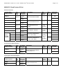
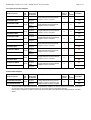
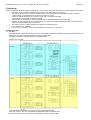
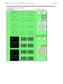
1
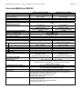
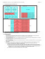
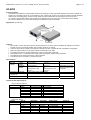
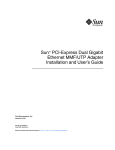
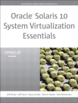
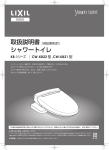
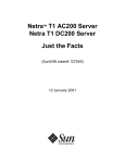
® SPARC Enterprise M5000 Server Issue Product Pages June 01, 2008 ® SPARC Enterprise M5000 38 SPARC® Enterprise M5000 Configuration Diagram New products: M5000-GR20, M5000-CL09-PI01, M5000-CL10-PI01, M5000-CL11-12-PI01 Withdrawn products: Some minor corrections: Chapter “Mounting additional Memory with different sizes” SystemArchitect PRIMEPOWER (PW) Hotline For further questions related to configurations for SE M5000 Systems with PC-ARCHITECT or SYSTEM-ARCHITECT do not hesitate to get in contact with SystemArchitect PRIMEPOWER (PW) Hotline: mailto:[email protected] Please add the respective configuration file (SAR-FILE)! Picture SPARC® Enterprise M5000 server Picture I/O Box for PCI expansion Product Facts ⏐ Issue: June 01, 2008 ⏐ Product: SPARC Enterprise M5000 ® Contents Recommended 19"- rack PRIMECENTER 2 with 1100 mm depth Overview M4000 and M5000 System Architecture Page 2 / 38 3 4 5 Product Overview SPARC® Enterprise M5000 Features 6 6 M5000 Server Product ID List 9 M5000 COD (Capacity on Demand) Server Product ID List 10 M5000 COD (Capacity on Demand) CPU Right to Use (License) Product ID List 10 M5000 Internal Storage Device Product ID List 10 M5000 Filter Product ID List 10 M5000 Power Cords for Rack internal use Product ID List 11 Rack integration order numbers 11 Power Cords for PSU connection directly to Rack external Jacks: 11 TM Solaris Operating System (OS) and other Software Product ID List 12 M5000 PCI Card Product ID List Ethernet Controller Serial Interface RS232 Controller Cryptographic Host Bus Adapters Fibre Channel Host Bus Adapters SCSI Host Bus Adapters 13 13 13 13 14 14 Console Connection 15 Ethernet Cables 17 Partitioning CPU Module 18 23 M5000 CPU Product ID List Additional Memory Module 24 25 M5000 Memory Product ID List Notes on Memory ordering: Memory Exception rules requires a “Request for Project Release”: Memory Mirroring Mounting additional Memory with different sizes Memory Interleaving I/O Board 25 26 26 26 27 29 30 M5000 second I/O Board Product ID List I/O-BOX 30 31 M5000 external I/O-Box Product ID List External storage units for M5000 33 34 External storage units for HDDs or MTC drives (differential SCSI) DN413 disk node for high performance HDD Hard Disk drives for DN413* Disk subsystems, cable connection diagrams with cable list Connecting Disk node DN413 to SCSI HBAs within single node configurations BG57 for accessible devices Order number for BG57 Drives for BG57 BG57 for accessible devices, cable connection diagrams with list of cables Connecting BG57 to controller with LVD I/F Service clearance M5000 Connectivity Further information and contacts 34 34 35 35 35 36 36 36 36 36 37 37 38 Product Facts ⏐ Issue: June 01, 2008 ⏐ Product: SPARC Enterprise M5000 ® Page 3 / 38 Recommended 19"- rack PRIMECENTER 2 with 1100 mm depth 24 HU height 38 HU height + 2 x 2 HU vertical + 3 x 2 HU vertical S26361-K826-V212 S26361-K826-V213 SPARC® Enterprise M5000 servers can be mounted in PCR2 Rack versions with 1100 mm depth. If the mounting kits do NOT fit to the required rack, please order additional kits separately. For more details refer to the Product Facts: PrimeCenter RackDesign Guide and Configuration PrimeCenter Rack. To integrate a server or I/O-Box into a Rack by Factory additional Order numbers are mandatory (see chapter “Rack integration order numbers”)! Safety Attention: To mount an M5000 server into a rack you have to take notice for the rules which are described in the “Installation Guide” for Form factor models. M5000 System Base Unit is only allowed to be mounted up to Rack height unit 27 (lowest system height unit) Up to 3 x M5000 serves in a common Rack are allowed! Primecenter_24 46 HU height + 4 x 2 HU vertical S26361-K826-V214 Primecenter_38 Primecenter_46 Installation of PRIMEPOWER servers and SPARC® Enterprise Servers in other 19" racks than PCR2 is supported only, if „the PRIMEPOWER - Rack Installation Guidelines for PRIMEPOWER systems“ are fulfilled. For more information see the FSC extranet at: http://manuals.fujitsu-siemens.com/servers/sparc/m4m5io-pc-rack-install-en-01.pdf Product Facts ⏐ Issue: June 01, 2008 ⏐ Product: SPARC Enterprise M5000 ® Page 4 / 38 Overview M4000 and M5000 Enclosure CPU / Processor Chips (multi-core, multi-thread (VMT)) Cores / Threads per System Cores / Threads per processor Chip Primary Cache per core SLC (Second Level Cache) per Processor Chip (2 cores) MBU (Mother Board unit) Max. Memory by using max DIMMs max DIMM Slots (DDR-II) Memory per expansion unit Multi domains (partitions) Minimum domain configuration Memory RAS feature IOU (I/O Unit, hereafter called I/O board) Internal PCI Slots Max. Internal Disks (2.5”SAS) Removal media On-board GbE port 1000Base-T On-board Serial External IO exp. Max. Number of IO-Boxes Max. Number of PCI slots (internal plus I/O-Boxes Redundant parts Hot-replacable parts (Hot swap) Dynamic degradation RAS Management RAS features XSCF - Interfaces SPARC® Enterprise M4000 Rack 6U 4 x 2.15GHz SPARC®64VI (2 per module) 8 / 16 SPARC® Enterprise M5000 Rack 10U 8 x 2.15GHz SPARC®64VI (2 per module) 16 / 32 2/2 Instruction 128 KB / Data 128 KB 5 MB 2 CPU Modules 4 CPU Modules (each 2 CPU chips on CPU Module) (each 2 CPU chips on CPU Module) 4 Memory Boards 8 Memory Boards (each 8 slots DDR-II SDRAM) (each 8 slots DDR-II SDRAM) 128 GB 256 GB 32 64 8GB, 16GB or 32 GB (8 DIMMs per unit) 2 4 1 CPU chip, 8 DIMMs, 2 PCI-Express slots at the smallest ECC, Advanced ECC 2 1 (second IOU is expansion) 4 PCI-E (8 lanes per PCI slot) 8 PCI-E (8 lanes per PCI slot) 1 PCI-X (133MHz) 2 PCI-X (133MHz) 2 4 DVD (Standard); DAT (Option) 2 4 (2 on each IOU) ----Yes 2 Boxes (each max 12 PCI slots) 4 Boxes (each max 12 PCI slots) mounted to 1 IOU, mounted to 2 IOU, occupies 4 internal PCI-E slots occupies 8 internal PCI-E slots 25 50 HDD*, PSU, FAN, PCI-Cards*, DIMMs** (*Software support & consideration on configuration are required; **Memory Mirror function) HDD, PSU, FAN, PCI-cards, I/O-Boxes, DAT CPU chips, memory, power supply units, fans, HDDs, PCI cards (only in multi-path configuration) XSCF All major components can be automatically deconfigured after rebooting, Deconfiguration minimizes system impact in case of an uncorrectable error Finer granularity to prevent propagation of errors Buses between ASICs are protected by ECC Memory mirroring (optional) 2 LAN interface 100Base-TX (RJ45) 1 serial port RS232 (RJ45) 1 RCI interface, Fujitsu/FSC proprietary interface 1 USB port (for service only) Product Facts ⏐ Issue: June 01, 2008 ⏐ Product: SPARC Enterprise M5000 ® Page 5 / 38 System Architecture PRIMECENTER 2 Rack deep 1100mm PC 24U, 38U, 46U LAN Console SPARC Enterprise M5000 10U Basic Config up to 8x CPU (up to 16 core) / 256 GB MEM / 4x Hard disk / 2x PCI-X and 8x PCI-express slot Up to 8 CPU, 4 Module (SPARC64 VI). Up to 16 core (2 Threads per core) 2.15GHz / 5MB SLC for 1 CPU (2 cores) CPU order# Type Serrial SEL[XY]1A1U 2 CPU, 2.15GHz on a Processor Module Management CPU Module CPU LAN HUB or CPU Module CPU CPU CPU Module CPU Solaris PC CPU LAN-Management 10/100 BaseT copper CPU Module CPU CPU This picture is an overall view only. Not all order numbers are inplemented in this picture. To follow the rules of the configuration diagram is mandatory! CPU Main Memory options: up to 256 GB within 4GB DIMMs MEM order# Type SEL[XY]2A1U 8 x 1 GB DIMM SEL[XY]2B1U 8 x 2 GB DIMM SEL[XY]2C1U 8 x 4 GB DIMM MEM MEM MEM MEM MEM MEM MEM MEM Memory Board MEM MEM MEM MEM MEM MEM MEM MEM MEM MEM MEM MEM MEM MEM MEM MEM Memory Board MEM MEM MEM MEM MEM MEM MEM MEM MEM MEM MEM MEM MEM MEM MEM MEM MEM MEM MEM MEM MEM MEM MEM MEM MEM Memory Board MEM MEM MEM MEM MEM MEM MEM MEM MEM MEM MEM MEM MEM MEM MEM or Memory Board Memory Board Memory Board Memory Board PCI-e (8 line) Internal I/O Board (standard) : 1 internal DVD (standard) PCI-e (8 line) 1 internal DAT (optional) .. PCI-e (8 line) PCI-e (8 line) PCI-X (133MHz) 2 internal disk bays (standard), Additional drives need to order the following HDD’s. SEP[XY]X3A11U 1 x 73GB 2,5” SAS 10k rpm . onboard 1 Gbit Copper LAN .. . . . .. PCI-e (8 line) Second (Internal) I/O Board (optional) : PCI-e (8 line) PCI-e (8 line) PCI-e (8 line) PCI-X (133MHz) 2 internal disk bays (standard), Additional drives need to order the following HDD’s. SEP[XY]X3A11U 1 x 73GB 2,5” SAS 10k rpm PSU I/O Expansion (PCI) Box (with 1 PCI-Express boat as standard) I/O Expansion (PCI) Box (with 1 PCI-X boat as standard) First Boat Standard . . PCI Slot PCI Slot PCI Slot PCI Slot PCI Slot PCI Slot PCI Slot PCI Slot SEN[YX]8BE1S I/O Expansion (PCI) Box (with 1 PCI-Express boat as standard) I/O Expansion (PCI) Box (with 1 PCI-X boat as standard) PCI Slot PCI Slot PCI Slot Second Boat optional; SEN[YX]8TE1U as PCI-Express OR SEN[YX]8TX1U as PCI-X PCI Slot OR PCI Slot PCI Slot PCI Slot PCI Slot Link Card Kit optional PCI Slot SEN[YX]8BE1S I/O Expansion (PCI) Box (with 1 PCI-Express boat as standard) SEN[YX]8BX1S I/O Expansion (PCI) Box (with 1 PCI-X boat as standard) First Boat Standard PCI Slot PCI Slot OR PCI Slot PCI Slot PCI Slot PCI Slot PCI Slot PCI Slot PCI Slot PCI Slot Link Card Kit optional SEN[YX]8BE1S I/O Expansion (PCI) Box (with 1 PCI-Express boat as standard) SEN[YX]8BX1S I/O Expansion (PCI) Box (with 1 PCI-X boat as standard) First Boat Standard PCI Slot PCI Slot PCI Slot 4U Link Card Kit optional PCI Slot PCI Slot PCI Slot PCI Slot Second Boat optional; SEN[YX]8TE1U as PCI-Express OR SEN[YX]8TX1U as PCI-X PCI Slot 4U Link Card Kit optional PCI Slot Second Boat optional; SEN[YX]8TE1U as PCI-Express OR SEN[YX]8TX1U as PCI-X PCI Slot 4U Link Card Kit optional PCI Slot PCI Slot PCI Slot PCI Slot PCI Slot D:GPDS2-DN413 Link Card Kit optional SCSI – HDD - JBOD 3U UltraSCSI I/O module or UltraSCSI I/O module or 7 disk bay 7 disk bay D:GPDS2-SV30 Redundant PSU 3U D:EPRCK-BG57 Peripheral Box 2x 2bay (1,6 inch hight) or 2x 1bay 3,2 inch hight) For changeable media drives! 1,6 inch hight 1,6 inch hight Fibre Channel 4Gb 2 port SG-(X)PCIE2FC-QF4 Fibre Channel 4Gb 1 port SG-(X)PCI1FC-EM4-Z Fibre Channel 4Gb 1 port SG-(X)PCI1FC-QF4 Fibre Channel 4Gb 2 port SG-(X)PCI2FC-EM4-Z Fibre Channel 4Gb 2 port SG-(X)PCI2FC-QF4 . 1,6 inch hight 1,6 inch hight . Serial (RS232) 8 port (X)2156A-2 Link Card Kit optional SEN[YX]8BX1S PCI Slot Fibre Channel 4Gb 2 port SG-(X)PCIE2FC-EM4 . PCI Slot First Boat Standard PCI Slot . 4U Link Card Kit optional PCI Slot Second Boat optional; SEN[YX]8TE1U as PCI-Express OR SEN[YX]8TX1U as PCI-X OR PSU SEN[YX]8BE1S PCI Slot Fibre Channel 4Gb 1 port SG-(X)PCIE1FC-QF4 onboard 1 Gbit Copper LAN SEN[YX]8BX1S PCI Slot . Fibre Channel 4Gb 1 port SG-(X)PCIE1FC-EM4 . . . . Four PSU standard, 2 default plus 2 redundancy OR Crypto Accelerator 6000 PCI-e (X)6000A onboard 1 Gbit Copper LAN 2 disk bays PSU 1 G-bit LAN Contr. PCI-e 2 port MMF (optic) (X)7281A-2 onboard 1 Gbit Copper LAN 2 disk bays PSU 1 G-bit LAN Contr. PCI-e 2 port UTP (copper) (X)7280A-2 . . <-> means OR . Memory Board U320 SCSI-Contr. PCI-e LVD 2 port SG(X)PCIE2SCSIU320Z or or or or Product Facts ⏐ Issue: June 01, 2008 ⏐ Product: SPARC Enterprise M5000 ® Page 6 / 38 Product Overview SPARC® Enterprise M5000 SPARC® ENTERPRISE M5000 is a midrange server developed using the expertise of Fujitsu and Sun Microsystems. It has been designed to be the best choice in mission-critical computing solutions. High scalability comes from eight CPU chips (16 cores) and is backed by exceptional reliability and excellent means for asset investment protection. Based on SMP (Symmetric Multi Processing) architecture it delivers high scalability without change to applications. Features 1. SPARC® ENTERPRISE M5000 is a scalable enterprise server. • Up to eight dual core CPU chips can be installed. • Up to 256 GB of memory and 50 I/O slots (when four I/O Boxes are connected) are supported for excellent scalability. • The maximum data transfer performance of 64 GB/s ensures excellent linear scalability up to 16 processor-cores in an SMP configuration. 2. ® Dual-core SPARC 64 VI processors are used in this server. • 90 nm copper wiring technology is used in the processor to provide higher performance at lower power consumption. • The dual-core processors have large caches (primary cache: instructions 128 KB + data 128 KB per CPU core; secondary cache: 5 MB per CPU chip) appropriate for enterprise class server systems. • Multi-core and multi-threading technologies ensure high parallel-processing performance. • Both the primary and secondary cache use ECC (Error Checking & Correction) for high reliability. • Registers and ALU are all parity protected. This further enhances the high reliability of the server. 3. Integrated high-reliability makes this server suitable for 24-hour operation. • All address/data paths between key LSIs, such as CPU chips, memory controllers, I/O controllers and system controllers, are ECC protected for higher reliability. • Key components are redundant and hot replacement is supported. Product Facts ⏐ Issue: June 01, 2008 ⏐ Product: SPARC Enterprise M5000 ® Page 7 / 38 4. Very flexible partitioning functions are provided. • Multiple independent systems can be built on a single server called partitions or domains. • Each partition can individually be configured. • Up to four partitions are supported. • The motherboard on which CPU- and memory-modules are mounted is sub-divided into eight parts, and the two I/O board are sub-divided into four. A combination of sub-parts from motherboard and I/O board form a partition, in maximum 4. 5. Partition independent processor based system control facility: XSCF (eXtended System Control Facility) • XSCF detects abnormal conditions and controls the system without relying on system status, such as CPU abnormality or system hang. (Mutual monitoring/abnormal CPU notification, fan rotation frequency monitoring/control, power monitoring/control, humidity/temperature monitoring, etc., are provided) • Monitoring/control of peripheral devices such as RCI-connected units (cluster nodes) and expansion cabinets is available via RCI (Remote Cabinet Interface). Remote power-on/off is also available. • The operational status of the server can also be monitored by XSCF. • The embedded partition control facility renders the need for an external control console terminal unnecessary. 6. Remote Customer Support • Remote Customer Support will be handled via Teleservice. 7. ServerView Enterprise Edition 2.0 is available for download in the FSC Software Pool. • ServerView Enterprise Edition 2.0 provides consolidated management of all FSC servers including PRIMEPOWER, SPARC® Enterprise, PRIMEQUEST and PRIMERGY. Server managing functions for all managed servers, such as hardware configuration display and status monitoring, are provided for system administrators via a unified GUI and standard operating processes. a. The status monitoring of all servers is available from a single management client. The status of key components, such as CPU/memory of each server, can be displayed in a unified tree view. b. When server components fail, SVS EE displays each event graphically together with the relevant message for prompt defective part location. c. Server management can be performed with unified operability. 8. The DR (Dynamic Reconfiguration) functions are supported. Product Facts ⏐ Issue: June 01, 2008 ⏐ Product: SPARC Enterprise M5000 ® 9. Page 8 / 38 Configuration Diagram of the Main Unit * Areas indicated in blue show components belonging to the base units; those indicated in red show options (purchased separately, but see also base unit description). 10. Hardware for M5000 • Motherboard The motherboard carries CPU modules and memory modules. Four CPU modules (eight CPU chips) and eight memory modules (64 DIMMs) can be mounted. The motherboard is part of the base unit. st • 1 I/O board (standard) The I/O board has a connection to two Hard Disk Drive bays, one DVD Drive bay and one DAT Drive bay. It contains two onboard LAN*2 ports, four PCI Express slots and one PCI-X slot. • 2nd I/O board (optional) The 2nd I/O board has a connection to two Hard Disk Drive bays. It contains two onboard LAN*2 ports, four PCI Express slots and one PCI-X slot. • System disk Each partition requires at least one system disk for Solaris-installation. System disks can be realized in any of the following ways. To improve system reliability it is recommended to duplicating (mirroring) the system disk. A) Mount a Hard Disk Drive in a disk bay inside the server. B) Ultra 320 SCSI cards, expansion file units together with external HDDs can also be used as system disks. C) When using SAN Boot, fibre channel cards, RAID devices and system disks must be prepared. Use a disk in a RAID device as the system disk. When installing the OS on the RAID device, you need to prepare another installation server, or use one partition as an installation server using method A) above. D) LAN Boot from other SPARC Enterprise Server is also possible. Product Facts ⏐ Issue: June 01, 2008 ⏐ Product: SPARC Enterprise M5000 ® Page 9 / 38 M5000 Server Product ID List PART NUMBER LONG DESCRIPTION SHORT DESCRIPTION Fujitsu-Siemens Computers SPARC® Enterprise M5000 server. Includes M5000 system, 2x 2.1GHz CPUs (1 2x 2.1GHz CPU Modules), 16GB system memory (2 ea. 8GB memory boards), 2x 73GB HDD, 4 PSU, 1 I/O tray SE M5000 2.1GHz 2P16GB 2x73GB SEFPBAA1S Fujitsu-Siemens Computers SPARC® Enterprise M5000 server. Includes M5000 system, 4x 2.1GHz CPUs (2x 2x 2.1GHz CPU Modules), 16GB system memory (2 ea. 8GB memory boards), 2x 73GB HDD, 4 PSU, 1 I/O tray SE M5000 2.1GHz 4P16GB 2x73GB SEFPBCA1S Fujitsu-Siemens Computers SPARC® Enterprise M5000 server. Includes M5000 system, 4x 2.1GHz CPUs (2x 2x 2.1GHz CPU Modules), 32GB system memory (2 ea. 16GB memory boards), 2x 73GB HDD, 4 PSU, 1 I/O tray SE M5000 2.1GHz 4P32GB 2x73GB SEFPCBA1S Fujitsu-Siemens Computers SPARC® Enterprise M5000 server. Includes M5000 system, 8x 2.1GHz CPUs (4x 2x 2.1GHz CPU Modules), 32GB system memory (4 ea. 8GB memory boards), 2x 73GB HDD, 4 PSU, 1 I/O tray SE M5000 2.1GHz 8P32GB 2x73GB SEFPCDB1S Fujitsu-Siemens Computers SPARC® Enterprise M5000 server. Includes M5000 system, 8x 2.1GHz CPUs (4x 2x 2.1GHz CPU Modules), 64GB system memory (4 ea. 16GB memory boards), 4x 73GB HDD, 4 PSU, 2 I/O tray SE M5000 2.1GHz 8P64GB 4x73GB M5000-GR20 Fujitsu-Siemens Computers SPARC® Enterprise M5000 server. M5000 2.1GHz Includes M5000 system, 2x 2.1GHz CPUs (1x CPU Module), 64GB system 2P64GB 2x146GB memory (2 ea. 32GB memory boards), 2x 146GB HDD, 4 PSU, 1 I/O tray. 1xI/O tray (included ATO BU SEFASY11S) M5000-CL09-PI01 Fujitsu-Siemens Computers SPARC® Enterprise M5000 server. Includes M5000 system, 6x 2.1GHz CPUs (3x CPU Modules), 64GB system memory (4 ea. 16GB memory boards), 4x 146GB HDD, 4 PSU, 2 I/O tray. (included ATO BU SEFASY11S) M5000 ATO 6P2.15GHz 64GB 4x146GB 2xI/O Tray M5000-CL10-PI01 Fujitsu-Siemens Computers SPARC® Enterprise M5000 server. Includes M5000 system, 6x 2.1GHz CPUs (3x CPU Modules), 96GB system memory (6 ea. 16GB memory boards), 4x 146GB HDD, 4 PSU, 2 I/O tray. (included ATO BU SEFASY11S) M5000 ATO 6P2.15GHz 96GB 4x146GB 2xI/O Tray M5000-CL11-12PI01 Fujitsu-Siemens Computers SPARC® Enterprise M5000 server. Includes M5000 system, 8x 2.1GHz CPUs (4x CPU Modules), 96GB system memory (6 ea. 16GB memory boards), 4x 146GB HDD, 4 PSU, 2 I/O tray. (included ATO BU SEFASY11S) M5000 ATO 8P2.15GHz 96GB 4x146GB 2xI/O Tray M5000 family: SEFPAAA1S Product Facts ⏐ Issue: June 01, 2008 ⏐ Product: SPARC Enterprise M5000 ® Page 10 / 38 M5000 COD (Capacity on Demand) Server Product ID List PART NUMBER M5000family: SEFRCDB1S LONG DESCRIPTION SHORT DESCRIPTION FSC SPARC Enterprise M5000 COD (Capacity On Demand) server. Includes 8x 2.15GHz CPUs (4 CPU boards with 2 x CPUs each, 5MB onchip L2 cache) and 64GB system memory (4 memory modules with 8 x 2GB DDR2 DIMMs), 4 x 73GB SAS hard disks, 1 DVD-ROM, 2x 1Gb Ethernet ports, 2 I/O trays with 8 PCI-E and 2 PCI-X slots total, 4 power supplies (includes redundancy and DPF). As minimum to each COD System 2 RTU (Right To Use) licenses are required (must be ordered together with the system)! M5CoD 2.1GHz 8P64GB 4x73GB 2xI/O tray M5000 COD (Capacity on Demand) CPU Right to Use (License) Product ID List PART NUMBER M5000 family: SELX9RU1S LONG DESCRIPTION SHORT DESCRIPTION FSC SPARC Enterprise Server COD 2.0 Right-To-Use (RTU) license for one Capacity-on-Demand (COD) CPU, for use with SPARC Enterprise M4000 and M5000 servers. CoD RTU license for 1 CPU (FF model) Note to COD: COD Licenses are automatically arranged by the service processor (XSCF) (see also: Server Administration Guide). Licenses can only manually be assigned to domains, but not to hardware components like CPU. If licenses are manually assigned to domains, the licenses will be automatically arranged to the CPU’s of this domain, first CPU gets first license which is assigned for this domain, second CPU gets second license and so on. If there is only one big domain, the arrangement is the same: First CPU gets first license which is assigned for this domain, second CPU gets second license and so on. Result for M5000: To use the second system-board in one big domain over the complete system a minimum of 5 licenses is necessary! In addition the “Note to Memory ordering” is also permissible for COD server! M5000 Internal Storage Device Product ID List Marketing P/N Option Description Maximum Number Supported per System Comments nd SEPX3A11U MR 73GB 10K RPM SAS Hard Disk Drive. Without factory integration! Up to 4 per M5000 SEPY3A11U MR 73GB 10K RPM SAS Hard Disk Drive. Factory integration only! Up to 4 per M5000 SEPX3C11U MR 146GB 10K RPM SAS Hard Disk Drive. Without factory integration! Up to 4 per M5000 MR 146GB 10K RPM SAS Hard Disk Drive. Factory integration only! DAT 72 Tape Drive. Without factory integration! DAT 72 Tape Drive. Factory integration only! Up to 4 per M5000 Up to 1 per M4000 Up to 1 per M5000 Up to 1 per M4000 Up to 1 per M5000 SEPY3C11U SELX9DT1U SELY9DT1U 2 I/O tray required for HDD 3 & 4 on M5000 2nd I/O tray required for HDD 3 & 4 on M5000 2nd I/O tray required for HDD 3 & 4 on M5000 2nd I/O tray required for HDD 3 & 4 on M5000 M5000 Filter Product ID List Marketing P/N SEEX9FL1U SEFX9FL1U Option Description M4000 air filter kit M5000 air filter kit Maximum Number Supported per System 1 per system 1 per system Comments Product Facts ⏐ Issue: June 01, 2008 ⏐ Product: SPARC Enterprise M5000 ® Page 11 / 38 M5000 Power Cords for Rack internal use Product ID List Attention: For each PSU a Power Cord must be ordered for Rack internal connection (thickly marked in table below) to the Socket strip! Note: M5000 requires 4x 16A power cords, each I/O-Box requires 2x 10A power cords. Power Cord, to a Rack internal Socket strip, 16 A For System Base Units! In combination with the PSU of the Base Units. & In combination with the PSU of the I/O Boxes. Is a Standard Part of each System PSU. Socket strip 1-phasen 32A SDL 1x 3 jacks IEC320 C19 (16A) 1x 2 jacks IEC320 C13 (10A) 1x plug IEC309 (CEEform blue (32A)) S26361-F2262-E132 Socket strip 3-phasen 32A SDL 3x 3 jacks IEC320 C19 (16A) 3x 2 jacks IEC320 C13 (10A) 1x plug IEC309 (CEEform red (32A)) S26361-F2262-E332 Power Cord, to a Rack internal Socket strip, 10 A S26361-F2262-L132 S26361-F2262-L332 SERXP333WS For I/O-Box! In combination with the PSU of the I/O Boxes. Socket strip 1x 10 jacks IEC320 C13 (10A) auf 1 x plug CEEform (16A) S26361-F2262-E40 Socket strip 1x 10 jacks IEC320 C13 (10A) auf 1 x plug NEMA L6-30 (For US / CAN.) S26361-F2262-E41 Socket strip 1 x 10 jacks IEC320 C13 (10A) auf 1 x plug IEC 320 C20 (16A) for UPS S26361-F2262-E42 Socket strip 3phase 3x 8 jacks IEC320 C13 S26361-F2262-L40 S26361-F2262-L41 S26361-F2262-L42 S26361-F2262-E31 S26361-F2262-L31 Rack mount Kit Socket strip Rack mount Kit 2U horizontal S26361-F2262-E301 S26361-F2262-L301 The offered Socket strips are documented in „ PRIMECENTER Rack Power Connection Concept “: http://extranet.fujitsu-siemens.com/vil/pc/vil/primergy/building_blocks/rack_systems/pf_primecenter-cable_en.doc Rack integration order numbers To integrate a server or I/O-Box into a Rack by Factory additional Order numbers are mandatory! Integrate a M4000 or M5000 server into a Rack by Factory RACK-SER2 Integrate a I/O-Box into a Rack by Factory RACK-SER1 Power Cords for PSU connection directly to Rack external Jacks: Must only be ordered for direct Power connections outside of the Rack to a country specific jack. Overview Order Numbers Power Cord: Description: It is recommended to order 1 Cord to each PSU: SELX9P21U MR AC Power Cord (for Continental Europe) Number of cables needed for M4000: 2 Number of cables needed for M5000: 4 Product Facts ⏐ Issue: June 01, 2008 ⏐ Product: SPARC Enterprise M5000 ® Page 12 / 38 Power supply unit and power supply connections SPARC® ENTERPRISE M5000 has 2+2 redundant power supply units (four in total). Connect the power supply units as follows. Single Power Feed Dual Power Feed HDD#1 HDD#0 HDD#3 HDD#2 DAT DAT Power Power Power Power supply supply supply supply unit #0 unit #1 unit #2 unit #3 If an uninterruptible Power Supply (UPS) is used it shall only supply one of the two power feeds. SolarisTM Operating System (OS) and other Software Product ID List ® The SPARC Enterprise M5000 servers come with the Solaris 10 Operating System preinstalled on an HDD. Order Numbers Media Kit: SOLZ9-100C9A7M Description: U24529-C590A Solaris 10 CD Set Premium Pack With additional SW-Components on the control DVD (ServerView Suite, etc.) This includes: SOLZ9-100C9A7M Solaris 10 (latest release) DVD Media Kit U24529-C503A control DVD Note: Must be ordered with each system if OS Media kit is not ordered! U24529-C592A Solaris 10 Accessories Kit SPARC® Enterprise Server Low End and Midrange and ESF CD (Partition DR, SCF interface etc.) U24529-C502A IPsec enabler CD for Crypto Accelerator 6000 Note: Can be ordered with Crypto Accelerator! X6099A Solaris 10 OS Media kit Solaris 10 (latest release) DVD Media Kit. Multilingual, no hardcopy documentation, no license. Note: Must be ordered with each system if Premium Pack is not ordered! Attention: One of these two positions must be ordered for each system! Must be ordered with each system! Product Facts ⏐ Issue: June 01, 2008 ⏐ Product: SPARC Enterprise M5000 ® Page 13 / 38 M5000 PCI Card Product ID List Ethernet Controller Overview Order Numbers options: PCI Bus type X7281A-2 Description Max within a System Max in an I/O-boat X-option PCI-e 7281A-2 X7280A-2 Fact.Integrat. 7280A-2 X4447A-Z Fact.Integrat. X-option PCI-e 4447A-Z X1027A-Z Fact.Integrat. 8 2 Yes Yes Dual Port Gb Ethernet UTP 1027A-Z X5558A ---- Fact.Integrat. X-option 5558A-Z ---- Fact.Integrat. X5560A-Z ---- X-option 5560A-Z ---- Fact.Integrat. 8 2 Yes Yes Quad Giga Ethernet UTP Adapter 8 incl. IO-Boats 2 10Gb Ethernet Dual Port Max 2 per Domain! 0 X-option PCI-e Supported in I/O-Box Yes Dual Port Gb Ethernet MMF X-option PCI-e Options for 10Gb controller for Factory Integration or X-option Transceiver (10GBASE-SR: 850nm, 300m, MMF). Transceiver (10GBASE-LR: 1310nm, 10km, SMF). Yes No No No In summery max. 2 per controller. --No No --No Serial Interface RS232 Controller Overview Order Numbers options: PCI Bus type: X2156A-2 for Factory Integration or X-option X-option PCI 2156A-2 Fact.Integrat. Description Serial Asynchronous Interface (SAI/P) adapter 3.0 Max within a System Max in an I/O-boat 2 0 Supported in I/O-Box No No Cryptographic Host Bus Adapters Overview Order Numbers options: PCI Bus type: X6000A Description Max within a System Max in an I/O-boat 2 0 X-option PCI-e 6000A for Factory Integration or X-option Fact.Integrat. Crypto Accelerator 6000 remarks Product Facts ⏐ Issue: June 01, 2008 ⏐ Product: SPARC Enterprise M5000 ® Page 14 / 38 Fibre Channel Host Bus Adapters Overview Order Numbers options: PCI Bus type: SG-XPCIE2FC-QF4 for Factory Integration or X-option X-option PCI-e SG-PCIE2FC-QF4 SG-XPCIE2FC-EM4 Fact.Integrat. X-option PCI-e SG-PCIE2FC-EM4 SG-XPCIE1FC-QF4 Fact.Integrat. X-option PCI-e SG-PCIE1FC-QF4 SG-XPCIE1FC-EM4 Fact.Integrat. X-option PCI-e SG-PCIE1FC-EM4 SG-XPCI2FC-QF4 Fact.Integrat. X-option PCI-X SG-PCI2FC-QF4 SG-XPCI2FC-EM4-Z Fact.Integrat. X-option PCI-X SG-PCI2FC-EM4-Z SG-XPCI1FC-QF4 Fact.Integrat. X-option PCI-X SG-PCI1FC-QF4 SG-XPCI1FC-EM4-Z Fact.Integrat. X-option PCI-X SG-PCI1FC-EM4-Z Fact.Integrat. Description Max within a System Max in an I/O-boat Dual 4Gb Fiber Channel Network Adapter, RoHS 6 compliant 8 6 Dual 4Gb Fiber Channel Network Adapter, RoHS 6 compliant 8 Single 4Gb Fiber Channel Network Adapter, RoHS 6 compliant 8 Single 4Gb Fiber Channel Network Adapter, RoHS 6 compliant 8 Dual 4Gb Fiber Channel Network Adapter, RoHS 6 compliant 2 Dual 4Gb Fiber Channel Network Adapter, RoHS 6 compliant 2 Single 4Gb Fiber Channel Network Adapter, RoHS 6 compliant 2 Single 4Gb Fiber Channel Network Adapter, RoHS 6 compliant 2 Supported in I/O-Box Yes Yes Yes 6 Yes Yes 6 Yes Yes 6 Yes No ---No No ---No No ---No No ---No SCSI Host Bus Adapters Overview Order Numbers options: PCI Bus type SG-XPCIE2SCSIU320Z X-option PCI-e SG-PCIE2SCSIU320Z Note: • for Factory Integration or X-option Fact.Integrat. Description PCI-E Dual channel Ultra320 low voltage differential SCSI host bus adapter includes standard and low profile brackets. RoHS 6 compliant Max within a System Max in an I/O-boat 6 2 Supported in I/O-Box Yes Yes SCSI Controller SG-(X)PCIE2SCSIU320Z using Solaris 10 Update 3 can only be placed in PCI-express slot #2, #3 or #4 from both IOUs, not in PCI-express slot #1 nor in I/O-Box which is connected to this slot! Using Solaris 10 Update 4 or higher versions this SCSI-Controller is also allowed in PCI-express Slot #1, see table above. Product Facts ⏐ Issue: June 01, 2008 ⏐ Product: SPARC Enterprise M5000 ® Page 15 / 38 Console Connection For APL a personal computer (PC) or workstation is required for system control and maintenance work. This console must be setup prior to installation of APL. The XSCF is accessed using this console. The console ports of each partition are accessed via XSCF. XSCF and the console need to be connected via LAN. If you forget the XSCF-sign on password, you will need to connect to XSCF via RS-232C for recovery. The customers console terminal should meet the following conditions. • https (or http) and ssh (or telnet) available (for details, see the following specifications). • The terminal needs to be placed within 15 m from the server. • A maintenance account (account for field engineer privileges) for field engineers set up in advance. (For details on account creation, see “eXtended System Control Facility User’s Guide”.) Where the customer has no prepared terminal, or the field engineer cannot use the terminal prepared by the customer, approval to use the field engineer’s own PC should be gained from the customer. Field engineers can connect their own PC to the XSCF via XSCF-LAN or RS-232C. (XSCF-LAN is used as standard. However, in special cases, if XSCF-LAN is not available or the XSCF-sign on password needs initialization, RS-232C is used.) Console connection example (field engineer uses a terminal setup by customer) Console connection example (field engineer uses a terminal setup by customer and the console path is duplicated) Note: For the HUB in the pictures our LAN Switch D:GP70F-AL21 can be ordered. Product Facts ⏐ Issue: June 01, 2008 ⏐ Product: SPARC Enterprise M5000 ® Page 16 / 38 Console connection example (Field engineer connects temporarily a PC via LAN (shown as blue line) or RS-232C (shown as dotted line) as required to provide maintenance) Note: For the HUB in the picture our LAN Switch D:GP70F-AL21 can be ordered. Console connection example (the console path is duplicated. Field engineer connects temporarily a PC via LAN (shown as blue line) or RS-232C (shown as dotted line) as required to provide maintenance) Note: For the HUB in the picture our LAN Switch D:GP70F-AL21 can be ordered. Product Facts ⏐ Issue: June 01, 2008 ⏐ Product: SPARC Enterprise M5000 ® Specifications for the PC (or the workstation, etc.) Description CPU Pentium3 1 GHz or greater SPARC® Memory 512 MB or greater OS Windows XP Windows2000 RedHat Linux Solaris I/O CD-ROM/DVD-ROM (either internal or external device is available) LAN (1000Base-T, 100Base-TX, or 10Base-T) RS-232C (not necessarily required) Browser Microsoft (R) Internet Explorer 6.0 or later Netscape Navigator (TM) 7.0 or later Mozilla 1.7 or later Terminal Solaris Secure Shell software Open SSH (SSH) Other terminal software with equivalent function Terminal software (RS-232C) Hyper terminal Other terminal software with equivalent function Connection type LAN via hub / switch D:GP70F-AL21 direct connection Page 17 / 38 Remarks Equivalent CPUs i.e. AMD are suitable. One of the OS listed on the left is required. One of the browsers listed on the left is required. One of the software items listed on the left is required to use SSH via LAN One of the software items on the left is required to use RS232C connection Cable type twisted-pair cable (category 5 UTP cable) TPCBL-B005 Number of cables used duplexed XSCF-LAN: 3 simplexed XSCF-LAN: 2 Remarks Purchased separately Fast Ethernet direct cable: DCBL-FEA05 simplexed XSCF-LAN: 1 Purchased separately RS-232C RJ45 - DSUB9 pin, inch screw, 1 female: DCBL-RSD05 (not necessarily required) * Before ordering cables check the product ID and length for suitability of configuration. Attached to the server Ethernet Cables Cables for Ethernet 1000 Base TX Product Number Description S26361-F3417-E500 UTP cat 5 enhanced, customized length S26361-F3417-L505 S26361-F3417-L510 S26361-F3417-L515 S26361-F3842-L5 S26361-F3842-E5 UTP cat 5 enhanced, 05m UTP cat 5 enhanced, 10m UTP cat 5 enhanced, 15m UTP cat 5 enhanced IC-cable, 5m Lose Remarks Cable only for Rack internal use if both targets are in a common rack! Please order “Factory integration” ! UTP category 5 enhanced patch cable for Gbit Ethernet (1000Base-T) to connect controllers with a hub or switch. UTP category 5 enhanced patch cable for Gbit Ethernet (1000Base-T) to connect controllers with a hub or switch. UTP category 5 enhanced crossover cable for Gbit Ethernet (1000Base-T) to make direct connection UTP cat 5 enhanced IC-cable, 5m Verbau between Ethernet controllers in a two node configuration Cables for Ethernet 1000 Base SX Please buy optical cables locally. Product Facts ⏐ Issue: June 01, 2008 ⏐ Product: SPARC Enterprise M5000 ® Page 18 / 38 Partitioning SPARC® ENTERPRISE M5000 supports partitioning in which a single server can be divided into multiple independent systems. • Partitioning creates multiple independent systems which are called partitions or domains. • The basic hardware resource required for partitioning is a Physical System Board (hereafter referred to as PSB). A PSB consists of a motherboard with or without connection to an IOU. • A PSB can logically be divided into four parts. In this case it is called a Quad-XSB. A PSB without such a division is called a Uni-XSB. • The physical unit configuration of each divided PSB part is called eXtended System Board (XSB). • Partitions can be configured to form a domain using any combination of XSBs. XSBs divided with Uni-XSB and QuadXSB can be mixed together within one domain. • The XSCF is used to configure a partition and specify the PSB division type. • Up to 4 partitions are supported. • A minimum of one system hard disk drive per partition is necessary as a boot device. PSB Division Types: 1) Uni-XSB The motherboard is divided into two physical system boards (PSB). Each PSB represents an own logical system in UNIXSB format. The entire motherboard cannot be used as a single PSB. Uni-XSB is equivalent to the PSB definition for PRIMEPOWER. Division Type: Uni-XSB The two PSBs are not divided and used as two logical system boards (SB). CPU chips, memory, PCI slots, hard disk drives assigned to XSB are predetermined. Mount as a minimum one CPU module and two MEM modules per operating XSB. Product Facts ⏐ Issue: June 01, 2008 ⏐ Product: SPARC Enterprise M5000 ® Page 19 / 38 If only one partition is configured with both PSBs in Uni-XSB mode but no CPU- and MEM-modules are mounted on PSB#1, then HDDs and PCI slots on the additional I/O board cannot be used (Areas shaded black in the figure below are not equipped with CPU- and MEM-modules). Product Facts ⏐ Issue: June 01, 2008 ⏐ Product: SPARC Enterprise M5000 ® 2) Page 20 / 38 Quad XSB Because Quad-XSB allows to configure several partitions in units of individual CPU chips (two cores) it is the optimized way to create small partitions. Quad-XSB is equivalent to the XSB definition for PRIMEPOWER. Division Type: Quad-XSB PSB (consists of 1/2 motherboard and an I/O board) is divided into four partitions with 1 CPU chip and a set of memory (8 DIMMs) each. PSBs can be divided into XSBs (XSB#0-0, XSB#0-1, XSB#1-0, XSB#1-1) with connection to an I/O board and XSBs (XSB#0-2, XSB#0-3, XSB#1-2, XSB#1-3) without connection to an I/O board. CPU chips, memory, PCI slots and disks are permanently assigned to the XSBs as shown in the diagram above. XSBs without connection to an I/O cannot be configured as an autonomous partition (refer to “8-4 Notes on Configurations” for details). Product Facts ⏐ Issue: June 01, 2008 ⏐ Product: SPARC Enterprise M5000 ® Example for four partitions configured with two XSBs. Page 21 / 38 Product Facts ⏐ Issue: June 01, 2008 ⏐ Product: SPARC Enterprise M5000 ® 3) Page 22 / 38 Combination of Uni-XSB and Quad-XSB PSBs divided into Quad-XSBs can be mixed together with Uni-XSB to configure a common partition. There is no difference in settings and conditions for partitions configured with Uni-XSB only or Quad-XSB only. This option is useful if only a partial memory mirroring within a certain partition is required but Uni-XSB-type XSB is too large to do so. PAR#0 in the following example is a partition configured by using both Uni-XSB and Quad-XSB. Product Facts ⏐ Issue: June 01, 2008 ⏐ Product: SPARC Enterprise M5000 ® Page 23 / 38 CPU Module Product Overview SPARC® ENTERPRISE M5000 servers use SPARC®64 VI processors, which are multi-core/multi-threading CPUs. Each module contains two CPU chips (4 cores). Up to four CPU modules can be installed in SPARC® ENTERPRISE M5000. Appearance CPU module for M4000/M5000 CPU module without cover viewed from the reverse side Features 90 nm copper wiring CMOS technology is used for these processors to provide high performance while achieving low power consumption. Two CPU cores are built on each CPU chip using CMP (Chip Multi-Processing) technology. CMT (Chip Multi-Threading) technology provides multi-thread processing that virtualizes each CPU core as two threads. The use of register renaming, out-of-order execution and non-blocking cache memory ensures high parallel-processing performance. These modules offer mainframe levels of reliability inherited from SPARC®64 V. • • Data in both primary and secondary caches are protected by ECC (Error Checking and Correction). • • Registers and ALU are protected by parity. • • If an error occurs, the hardware re-executes the instruction that triggered the error. (Not all errors are covered by this feature.) • • If recoverable errors occur frequently in cache, hardware-set degrade mode is automatically invoked. Product Facts ⏐ Issue: June 01, 2008 ⏐ Product: SPARC Enterprise M5000 ® Specifications Items CPU Type Frequency Primary cache Secondary cache Expansion unit Target servers Page 24 / 38 Specifications SPARC®64 VI 2.15 GHz Instructions: 128 KB data: 128 KB Both the instruction and data: 5 MB Remarks per core per CPU (2 cores) 1 CPU module (2 CPU chips, 4 cores) SPARC® ENTERPRISE M4000 ® SPARC ENTERPRISE M5000 M5000 CPU Product ID List Marketing P/N Option Description Dual-processor Modules MR 2x 2.1GHz processor module. Without factory integration! SELX1A1U MR 2x 2.1GHz processor module. Factory integration only! SELY1A1U Maximum Number Supported per System Comments 2 per M4000 4 per M5000 2 per M4000 4 per M5000 Purchase “Factory-installed modules” if you need the CPU modules installed and shipped inside the server. “Field expansion modules” are always shipped uninstalled even if they are purchased together with the server. Product Facts ⏐ Issue: June 01, 2008 ⏐ Product: SPARC Enterprise M5000 ® Page 25 / 38 Additional Memory Module Product Overview SPARC® ENTERPRISE M5000 memory module is an expansion memory device consisting of memory DIMMs and a memory controller equipped on a board that can be plugged to the motherboard. There are 8 GB, 16 GB, and 32 GB additional memory module types with eight DIMMs each which can be added as a set. Mounting of additional memory modules must be performed under specific conditions. For details on how to add memory refer to “Conditions for Mounting Additional Memory”. Appearance Memory Module Memory module without a cover (Memory module: 8 DIMMs are always mounted) Features (1) 1 Gbit / 2 Gbit / 4 Gbit DDR2 SDRAM (Double Data Rate Synchronous Dynamic Random Access Memory) is used to provide high-speed access. (2) High-density DIMMs (Dual Inline Memory Module) are used to save space on the motherboard. (3) ECC (Error Checking and Correction) functions provide higher system reliability. (4) If a single memory chip on a DIMM fails completely, it is handled as a single-bit error. This technique drastically reduces the number of system shutdowns caused by memory failures. (5) Memory mirroring function enables continued operation even when an uncorrectable error (multi-bit error) occurs. (6) When memory failure is detected at initial diagnosis or during OS operation, Block Degradation or Area Degradation occurs. Because the area to be degraded is designed to be a controllable minimum area, other areas remain intact. Thus, operation can continue/resume using these areas. This minimizes the effects of failures. (7) MEM controller patrols memory during normal operation independently from the CPU and OS. This hardware can detect an error and degrade the area before either the OS or an application is affected. This procedure doesn’t have any effect on other operations. M5000 Memory Product ID List Maximum Number Supported per System Option Description Comments 8GB MR with server memory board and 8x 1GB DIMMs. 4 per M4000 SELX2A1U Without factory integration! 8 per M5000 8GB MR with server memory board and 8x 1GB DIMMs . 4 per M4000 Factory integration only! SELY2A1U 8 per M5000 16GB MR with server memory board and 8x 2GB DIMMs. 4 per M4000 SELX2B1U Without factory integration! 8 per M5000 16GB MR with server memory board and 8x 2GB DIMMs. 4 per M4000 SELY2B1U Factory integration only! 8 per M5000 32GB MR with server memory board and 8x 4GB DIMMs. 4 per M4000 SELX2C1U Without factory integration! 8 per M5000 32GB MR with server memory board and 8x 4GB DIMMs. 4 per M4000 SELY2C1U Factory integration only! 8 per M5000 Purchase “Factory integration only” modules if you need the memory modules installed and shipped inside the server. “Without factory integration” means modules are always shipped uninstalled even if they are ordered with the server. Marketing P/N Product Facts ⏐ Issue: June 01, 2008 ⏐ Product: SPARC Enterprise M5000 ® Page 26 / 38 Notes on Memory ordering: • Two sets of memory modules with the same size (16 DIMMs) must be mounted on a physical system board as a minimum. 8 DIMMS are always handled as one set. • When adding memory, two sets of memory modules with the same size must be added at the same time. Memory can only be added in increments of 2x eight DIMMs. Only 2, 4, 6 or 8 Memory Modules are allowed. • For mixing DIMMs with different sizes special conditions have to be noticed, see chapter ”Mounting additional Memory with different sizes”. • If Memory Modules are installed on the second physical System Board a CPU-module on this PSB is mandatory and vice versa. • If a second internal I/O-tray is installed, at least one CPU-module and two Memory modules on the second physical System Board are mandatory (see also Memory Exception rules). • Min of 1 memory module per processor in Quad XSB Mode Hint: When ordering 4Gb DIMMs the customer has to specify how FSC shall deal with the memory which comes with the base configuration. It can either be delivered in a separate package or placed in MEM slots which remain open. Memory Exception rules requires a “Request for Project Release”: • • • To keep the initial costs low it is allowed as an exception to run a physical system board with only one MEM-module. This is allowed for PSB#0 or PSB#1 or both of them. This is meaningful in cases where a basic server configuration with only two MEM modules is ordered together with an additional 2nd I/O-tray. To get the 2nd I/O tray working you have to move a CPU module and a MEM module from the first PSB to the second PSB. PSBs with only one MEM module can only be configured in Uni-XSB mode, but not in Quad-XSB mode. If you run a PSB with only one MEM module you have to be aware of the risk in case: Of uncorrectable memory errors. In such a case the partition will panic and will not be bootable again, until the memory fault is solved. If reconfigured to quad-XSB the CPU module, which is placed in a XSB without memory, will be disabled. Memory Mirroring SPARC® ENTERPRISE M5000 models provide hardware based memory mirroring to avert system downs even when multi-bit errors are detected. Features: • Memory mirroring is available in both Uni-XSB and Quad-XSB configurations. In Quad-XSB configuration, however, mirroring should be configured in units of four XSBs (the same size as with Uni-XSB configuration). Mirroring cannot be configured using a single XSB. • Mixed configurations of mirrored and unmirrored SB/XSB in one partition are supported (on M5000). • Memory mirroring configuration is performed from the XSCF. For more information, refer to “eXtended System Control Facility User’s Guide”. • When mirroring is configured, the available memory capacity on each SB/XSB one-half of the total size. • Mirroring is done within a group using combinations as shown below. Thus, the memory size in Groups A and B can be different. Product Facts ⏐ Issue: June 01, 2008 ⏐ Product: SPARC Enterprise M5000 ® Page 27 / 38 Mounting additional Memory with different sizes ® MEM in SPARC Enterprise M5000 is organized on each SB separately in two groups: • Max. 16 DIMMs mounted in MEM#xA slots at SB#0 defined as Group A of SB#0. • Max. 16 DIMMs mounted in MEM#xB slots at SB#0 defined as Group B of SB#0. • In Group B at SB #0, all DIMMs must have the same Capacity. In Group A at SB #0, all DIMMs must have the same Capacity and this Capacity must be equal or bigger than the DIMMs of Group B. This DIMM Mix within a SB is possible in Uni-XSB and Quad-XSB Mode. • Max. 16 DIMMs mounted in MEM#xA slots at SB#1 defined as Group A of SB#1. • Max. 16 DIMMs mounted in MEM#xB slots at SB#1 defined as Group B of SB#1. • In Group B at SB #1, all DIMMs must have the same Capacity. In Group A at SB #1, all DIMMs must have the same Capacity and this Capacity must be equal or bigger than the DIMMs of Group B. This DIMM Mix within a SB is possible in Uni-XSB and Quad-XSB Mode. • Memory configurations and arrangements on SB#0 and on SB#1 can be different. • On each used SB a minimum of one CPU Module and two Memory Boards are necessary. The optional second I/O-Board also requires the minimum of CPU and Memory on SB#1. Logical diagram of memory locations Motherboard Memory Board #0 MEM#0B MEM#1B MEM#2B MEM#3B MEM#0B MEM#1B MEM#2B MEM#3B MEM#3A MEM#2A MEM#1A MEM#0A CPU Chip #0 CPU Modul #0 I/O-Board (base) Slots for: HDD#0 HDD#1 Memory Board #1 MEM#3A MEM#2A MEM#1A SB#0 MEM#0A CPU Chip #1 DAT Gigabit Ethernet Memory Board #2 MEM#3B MEM#2B MEM#1B MEM#0B MEM#3A MEM#2A MEM#1A MEM#0A CPU Chip #2 DVD-ROM Gigabit Ethernet PCI-X PCI-Express CPU Modul #1 PCI-Express Memory Board #3 MEM#3B MEM#2B MEM#1B MEM#0B MEM#3A MEM#2A MEM#1A MEM#0A CPU Chip #3 PCI-Express Group B Group A Memory Board #4 MEM#0B MEM#1B MEM#2B MEM#3B MEM#0B MEM#1B MEM#2B MEM#3B MEM#3A MEM#2A MEM#1A MEM#0A CPU Chip #4 PCI-Express CPU Modul #2 I/O-Board (optional) Slots for: HDD#2 HDD#3 Memory Board #5 MEM#3A MEM#2A MEM#1A SB#1 MEM#0A CPU Chip #5 Gigabit Ethernet Memory Board #6 MEM#3B MEM#2B MEM#1B MEM#0B MEM#3A MEM#2A MEM#1A MEM#0A CPU Chip #6 Gigabit Ethernet PCI-X PCI-Express CPU Modul #3 PCI-Express Memory Board #7 Group B MEM#3B MEM#2B MEM#1B MEM#0B Group A MEM#3A MEM#2A MEM#1A MEM#0A CPU Chip #7 PCI-Express PCI-Express Product Facts ⏐ Issue: June 01, 2008 ⏐ Product: SPARC Enterprise M5000 ® Page 28 / 38 Mounting Conditions for Memory with different sizes Condition 1: To mix different DIMM types on a certain SB see chapter “Mounting additional Memory with different sizes”. Condition 2: Two sets of memory modules with the same size (16 DIMMs) must be mounted. When adding memory, two sets of memory modules with the same size must be added at the same time. Condition 3: When mounting DIMMs to a specific group, the memory size must be identical within this group. DIMMs of different memory sizes cannot be mounted within a group. Condition 4: Memory size in Group A must be greater than or equal to that in Group B. These rules are true for mirrored and not mirrored memory configurations. When mounting additional memory with different memory sizes transfer already-mounted DIMMs as necessary and follow the above conditions. Example of Memory Expansion for SB#0 Product Facts ⏐ Issue: June 01, 2008 ⏐ Product: SPARC Enterprise M5000 ® Page 29 / 38 Memory Interleaving Memory interleaving is a technique that divides main memory into several blocks (WAYs) and accesses each WAY independently and in parallel to enable effective access to the contiguous area. The size of one WAY is 64 bytes, which is the line size of cache memory. ® SPARC ENTERPRISE M4000 / M5000 perform memory interleaving in Group units as standard. The number of WAYs in each configuration is as follows. Uni-XSB configuration (16 DIMMs of memory are mounted in Groups A and B) Uni-XSB configuration (8 DIMMs of memory are mounted in Groups A and B) Quad-XSB configuration Product Facts ⏐ Issue: June 01, 2008 ⏐ Product: SPARC Enterprise M5000 ® Page 30 / 38 I/O Board (also called I/O tray or I/O Unit (IOU)) Product Overview The SPARC® ENTERPRISE M5000 basic configuration contains one I/O board. A second I/O board can be added to SPARC® ENTERPRISE M5000. Appearance Features • The I/O board provides four PCI-Express slots and one PCI-X slot. *1 • The I/O board has two on-board Gigabit Ethernet ports and SAS-connections to two hard disk drives. • The first I/O board has a connection to the DVD-drive and to the optional internal DAT drive*2. Specifications Items On-board I/O Internal PCI slot Maximum number of HDDs Internal optical drive*2 Internal tape device*2 Specifications Internal I/O Unit 2x 1000Base-T*1 ports 4 slots PCI-Express, each 8 lanes 1x PCI-X: 1 slot Connection to 2 HDDs Connection to 1x DVD drive (DVD-ROM: 8X, CD-ROM: 24X) Connection to 1x DAT72 Remarks Are in base unit as standard. M5000 second I/O Board Product ID List Marketing P/N Option Description Maximum Number Supported per System SEFX61U MR I/O Tray (4 PCIe and 1 PCI-X slots) . Without factory integration! Up to 1 per M5000 SEFY61U MR I/O Tray (4 PCIe and 1 PCI-X slots) . Factory integration only! Up to 1 per M5000 Comments Note for chapter I/O Board *1: Notes on LAN connection LAN ports on the I/O Board and on LAN PCI Express cards belonging to the same partition have the same MAC address by default. Therefore, do not connect them to the same subnet before you have changed the default MAC address. You can assign unique MAC addresses to respective LAN ports by changing the OBP environment variable “local-mac-address?” to “true”. *2: DVD-ROM drive and the internal DAT drive cannot be connected to the expansion (second) I/O board of the SPARC® ENTERPRISE M5000. Product Facts ⏐ Issue: June 01, 2008 ⏐ Product: SPARC Enterprise M5000 ® Page 31 / 38 I/O-BOX Product Overview The External I/O Expansion Unit (hereafter referred to as I/O Box) is a rack-mountable expansion unit used to expand the server’s I/O connectivity with up to 12 PCI Express or PCI-X slots. Each I/O-box can contain two External I/O kits (hereafter referred to as I/O boats) (giving 12 slots in total). Each I/O boat provides either six PCI Express or six PCI-X slots. To connect to the I/O boat insert a Link Card into a PCI Express slot on the server and connect them with a cable kit. Up to four I/O Boxes can be connected resulting in 48 external PCI slots for a M5000 Appearance (provisional): Features • Each I/O Box comes with one I/O boat for six PCI Express or six PCI-X slots as standard. By adding a second PCI Express or PCI-X I/O boat the I/O Box can provide a maximum of 12 slots. • There are two kinds of expansion I/O boats; PCI Express and PCI-X. Mixed I/O boat configuration is supported. • Both PCI Express and PCI-X slot types support PCI HotPlug for I/O cards. • Hot replacement and hot system expansion for each I/O boat is also supported. • Each I/O Box has 1+1 redundant power supply units and supports single or dual power feed. • Hot replacement for each power supply unit is supported. • The I/O Box can be mounted in a 19-inch rack (4U). Specifications Items Slot type, number In base system Maximum number Redundant components Hot replaceable components Target servers Specifications PCI Express: 6 Remarks PCI-X: 6 PCI Express: 12 PCI-X: 12 or or PCI Express: 6 and PCI Express: 6 and PCI-X: 6 PCI-X: 6 Power supply units, power system PCI cards, I/O boats, power supply units depending on the I/O boat types which are mounted M4000/ M5000 IO boat PCI Slot Specifications I/O boat for PCI Express PCI Bus Slot No. LINK0 PCI Express PCIE1 PCIE2 PCIE3 PCIE4 PCIE5 PCIE6 I/O boat for PCI-X PCI Bus Slot No. LINK0 PCI-X PCIX1 PCIX2 PCIX3 PCIX4 PCIX5 PCIX6 No. of Lanes Card Size for exclusive use with a Link Card 8 L 8 L 8 L 8 L 8 L 8 L Bus Width Clock Rate Input Voltage Card Size for exclusive use with a Link Card 64/32 bit 64/32 bit 64/32 bit 64/32 bit 64/32 bit 64/32 bit 133 MHz 133 MHz 133 MHz 133 MHz 133 MHz 133 MHz 3.3 V/Universal 3.3 V/Universal 3.3 V/Universal 3.3 V/Universal 3.3 V/Universal 3.3 V/Universal L L L L L L Product Facts ⏐ Issue: June 01, 2008 ⏐ Product: SPARC Enterprise M5000 ® Page 32 / 38 PCI Bus: LINK0: indicates the types of I/O boat. indicates slots where Link Cards, separately purchased PCI cards for connecting the server and the I/O Box, are mounted. No. of Lanes: indicates the width of PCI Express slot lane and shows eight lanes are supported. Bus Width: shows PCI slots support a 64-bit width, and any PCI card with a 64-bit or 32-bit width can be used. Clock Rate: indicates operating frequencies supported by each PCI slot. When a 133 MHz operable PCI card is installed, the clock rate becomes 133 MHz. Input Voltage: indicates the voltage levels of PCI cards that can operate in the slot. 3.3 V PCI cards and universal PCI cards (PCI cards that can work at either 3.3 V or 5 V) can be mounted in any slot. PCI cards that only work in 5 V slots cannot be used. Card Size: S indicates short length PCI cards and L indicates long length PCI cards can be installed. Connection Types (example) Connection between server and I/O Box is realized by Fibre or Copper Link Card Kit (Link Card) and a dedicated cable set (Link cable). Insert the Link Card in a PCI Express slot on the server. Cascade connection of I/O boats is not supported. Expansion M5000: Up to 4 external I/O Boxes with 2 boats each are connectable (second internal IOU must be installed for third and fourth external I/O-Box). Each I/O boat is connected directly to the server and occupies one PCI-express slot in internal IOU. Product Facts ⏐ Issue: June 01, 2008 ⏐ Product: SPARC Enterprise M5000 ® Page 33 / 38 M5000 external I/O-Box Product ID List Marketing P/N SENX8BE1S SENX8BX1S SENY8TE1U SENX8TE1U SENY8TX1U SENX8TX1U SELY8LK1U SELX8LK1U SENY8LK2U SENX8LK2U SENY8LK3U SENX8LK3U SENX8FC1U SENX8FC2U Option Description PCI-Express External I/O Expansion Unit, w. 2x PSUs, w 1 PCI-E Boat, ROHS-6 If “Factory integration” will be accomplished or not depends on order sequencing! PCI-X External I/O Expansion Unit, w. 2x PSUs, w 1 PCI-X Boat, ROHS-6 Without factory integration! If “Factory integration” will be accomplished or not depends on order sequencing! Current Status: For order of PCI-X I/O-Box a Request for Special Release is necessary! PCI-Express IO-Boat for External I/O Expansion Unit, ROHS-6 Factory integration only! PCI-Express IO-Boat for External I/O Expansion Unit, ROHS-6 Without factory integration! PCI-X IO-Boat for External I/O Expansion Unit, ROHS-6 Factory integration only! Current Status: For order of PCI-X I/O-Boat a Request for Special Release is necessary! PCI-X IO-Boat for External I/O Expansion Unit, ROHS-6 Without factory integration! Current Status: For order of PCI-X I/O-Boat a Request for Special Release is necessary! 1x copper Link card Kit (2 boards + 2 x 4M copper cables) for External I/O Expansion Unit. Factory integration only! 1x copper Link card Kit (2 boards + 2 x 4M copper cables) for External I/O Expansion Unit. Without factory integration! 1x Optical Link card Kit (2 boards + 2 10M optical cables) for External I/O Expansion Unit. Factory integration only! 1x Optical Link card Kit (2 boards + 2 10M optical cables) for External I/O Expansion Unit. Without factory integration! 1x Optical Link card Kit (2 boards + 2 x 25M optical cables) for External I/O Expansion Unit. Factory integration only! 1x Optical Link card Kit (2 boards + 2 x 25M optical cables) for External I/O Expansion Unit. Without factory integration! 1x Optical Link Cable Set (10m optical cable) for External I/O Expansion Unit. Without factory integration! 1x Optical Link Cable Set (25m optical cable) for External I/O Expansion Unit. Without factory integration! Comments FSC Ext I/O Exp Unit, 1 PCI-E FSC Ext I/O Exp Unit, 1 PCI-X currently without Controller support! PCI-E IO-Boat for I/O Exp Unit PCI-E IO-Boat for I/O Exp Unit PCI-X IO-Boat for I/O Exp Unit currently without Controller support! PCI-X IO-Boat for I/O Exp Unit currently without Controller support! copper Link Card Kit, 4 M copper Link Card Kit, 4 M Optical Link Card Kit, 10 M Optical Link Card Kit, 10 M Optical Link Card Kit, 25 M Optical Link Card Kit, 25 M Optical Link Cable only, 10m Optical Link Cable only, 25m Notes: - To connect to a server each I/O boat requires its own Link Card Kit. The Link Card Kits are not included in the basic I/O Box configuration and must be purchased separately. - It is not supported to connect the two IO boats within one I/O-Box to different servers. If two I/O boats are equipped they have to be connected to the same server. Product Facts ⏐ Issue: June 01, 2008 ⏐ Product: SPARC Enterprise M5000 ® Page 34 / 38 External storage units for M5000 External storage units for HDDs or MTC drives (differential SCSI) DN413 disk node for high performance HDD Overall view disk nodes (new generation) Disk node Drive interface Node interface Capacity per disk Maximum capacity / disk node Cabinet type Redundant components Controller to connect (HBA) Throughput Maximum cable length Max. number of DN413 per dual port HBA RAID level Cluster Required additional components DN413 U320 SCSI Wide (LVD) U320 SCSI Wide (LVD) 73 GByte, 146 GByte, 300 GByte 2x (7x300) = 4.2 TByte 19" rack-mount (3 HU) Fan (std), PSU/DPF (option) SG-(X)PCIE2SCSIU320Z 2x 320 MByte/s 10 m 1x DN413 = 4 TByte 0, 1 by SW NO 1 - 2 cables, 1 – 2 HBA, 1 – 14 Disk’s (FP81, FP84 or FP85, FP86) Rack for mounting. Disk nodes DN413 are for single server nodes. For the order numbers see table below. Order number for disk node DN4x D:GPDS2-DN413 Disk Subsystem D:GPDS2-SV30 Power supply unit Disk Subsystem for single node configuration 2 SCSI strings with 7 HDD bays each for disks with SCSI U320 LVD I/F 2 SCSI connection module single port U320 rack-mountable box, needs 3U in a 19“-rack 1 cable carrier (ZB527) and 1 support bracket (ZB5211) for 19“-rack BG5x are included Power supply unit, providing redundant PSU configuration for D:GPDS2-DN413. The redundant PSU adds dual AC power input/feed to GPDS2- DN413 NOTES on electrical connection and installation of the box The " Disk Node " (DN413) can be installed in the 19-inch rack PRIMECENTER. The plug (IEC320) of the AC power cord, which is shipped with GPDS2-DN413, matches with the outlets of the multiple socket outlets in the 19" rack. The GPDS2-DN413 has two AC power cords if a redundant PSU is installed. Note that the boxes do support dual AC power input/feed when a redundant PSU is installed. To support dual AC power input/feed the AC power cords (of standard PSU and redundant PSU) must be plugged into independent power grids (circuits) within the building's wiring. When connecting the cables from standard PSU and redundant PSU to the same power grid (circuit) within the building's wiring, you will get redundant power supply functionality instead of dual AC power supply functionality. As long as standard PSU and redundant PSU are working accurately, they share the output load. The outputs of all PSUs are connected in parallel. NOTES on ordering The (basic) disk node for 19" rack (GPDS2- DN413) does NOT include HDDs. HDDs must be ordered as separate items. To configure DN413 with redundant power supply or support dual AC power input/feed, a redundant PSU (GPDS2-SV30) must be ordered. The maximum Disks are 7 per SCSI string and 14 per Disk Node Box GPDS2-DN413. Standard cable carrier and support brackets for 19” racks PCR2 (BG5x) All basic boxes for DN413 include support brackets. 1 cable carrier (ZB527) for mounting within 19“ rack BG5x belongs to all DN413 The diagnostic is done via SCSI in band SAF-TE (SCSI Access Fault-Tolerant Enclosure). Daisy chaining of disk nodes/ packages DN413) or daisy chaining of the 2 strings of one disk node is not supported. The disk node DN413 comes without SCSI cable. 1 SCSI cable has to be ordered for each connection from a SCSI string (=7 HDD bays) to a SCSI controller within a node as separate items. Order numbers see below chapter drawing. You may connect the 2 strings of a disk node DN413 to different compute nodes. The DN413 is switched ON/OFF by "terminator power“ from the SCSI controller, i.e. ON with ON of the first compute node and OFF with OFF of the last compute node. If the temperature inside the DN413 reaches an abnormal level (because of a fatale error), all connected compute nodes shut down and switch off the disk node. Product Facts ⏐ Issue: June 01, 2008 ⏐ Product: SPARC Enterprise M5000 ® Page 35 / 38 Hard Disk drives for DN413* D:GPDS2-FP81 D:GPDS2-FP84 D:GPDS2-FP85 D:GPDS2-HDP3 D:GPDS2-HDP4 D:GPDS2-FP86 D:GPDS2-HDP5 73 GByte 15,000rpm, Ultra SCSI LVD320 Fast drives with short access time Hard disk U320 10k 146 GB 146 GByte 10,000rpm, Ultra SCSI LVD320 Hard disk U320 10k 300 GB 300 GByte 10,000rpm, Ultra SCSI LVD320 HD bundle with 4 x 73 GB 15Krpm 292 GByte of disk space, 4 drives 73 GByte each 584 GByte of disk space, 4 drives 146 GByte each HD packet with 4 x 146 GB U320 10Krpm Allowed in DN413. 73 GByte 15,000rpm, Ultra SCSI LVD320 Hard disk 73GB 15kRpm Fast drives with short access time 292 GByte of disk space, 4 drives 73 GByte and 15,000rpm HD bundle with 4 x 73 GB 15Krpm each Hard disk 73GB 15kRpm NOTES on disks for DN413: These HDDs can be mounted in „DN413 boxes“ only, but NOT in system cabinets. Disk subsystems, cable connection diagrams with cable list Connecting Disk node DN413 to SCSI HBAs within single node configurations (up to 320 MByte/s) DN413 is not usable for shared disks in cluster configurations. D:GPDS2 -DN413 Disk Subsystem Dual Port 3U UltraSCSI I/O module F LVD-SCSI PCI – U320 HBA 7 disk bay UltraSCSI I/O module 7 disk bay D:GPDS2 - SV30 Redundant PSU The second UltraSCSI I/O module in this drawing can either be connected to the second port of a DualPort HBA or to another HBA which may or may not belong to another partition. Cables for connecting disk nodes -DN413 to U320 SCSI HBA (up to 320 MByte/s) D:GPDS2-KB04 SCSI cable UHD68(S)-UHD68(S) 4m (DN41*) D:GPDS2-KB05 SCSI cable UHD68(S)-UHD68(S) 5m (DN41*) F D:GPDS2-KB10 SCSI cable UHD68(S)-UHD68(S) 10m (DN41*) SCSI cable UHD68(S)-UHD68(S), customized length SNP:SY-F2365E500-P needed, if the rack internal cabling shall be done by factory. Note on cable carrier: The cable carrier GPRAC-ZB527 requires additional cable length of approx. 1m Product Facts ⏐ Issue: June 01, 2008 ⏐ Product: SPARC Enterprise M5000 ® Page 36 / 38 BG57 for accessible devices Order number for BG57 D:EPRCK-BG57 D:EPRCK-AN60 D:EPRCK-AN62 D:EPBOX-AN55 Rack-mountable box, 3 HU, 4 bays (1.6” high) 2 SCSI strings (2 bays each) as standard 19" Rack Box f. changeable Peripheral 4 SCSI strings (1 bay each) with optional EPRCK-AN60 2channel U160 1 SCSI strings (4 bays) with optional EPRCK-AN62 Each SCSI string may be connected to a different server. Note: NO redundant PSU available. For configurations with 4 SCSI strings with 1 bay each or 3 Upgrade kit PW BG57 to 4channel U160 strings with 2x1 plus 1x2 bays. Change kit PW BG57 to 1channel U160 For connecting the 4 bays of one BG57 to 1 SCSI string 1 adapter AN55 required for each 8-bit device within a Adoption set for 8bit SE devices BG55/BG57 box Drives for BG57 D:EPBOX-MC57 MTC DAT72, 36-72GB, box D:EPBOX-MC77 MTC 8mm, 80-160GB D:EPBOX-MC88 MTC LTO 2 HH, 200/400GB 36 GByte (native) to 72 GByte (compressed) 16bit Install in EPRCK-BG57 rack mountable box only LVD Do NOT mix with 8bit drive within 1 box Current Control²CD required 80 GByte (native) to 160 GByte (compressed) 16bit Install in EPRCK-BG57 rack mountable box only LVD Do NOT mix with 8bit drive within 1 box Current Control²CD required 200 GByte (native) to 400 GByte (compressed) 16bit Install in EPRCK-BG57 rack mountable box only LVD Do NOT mix with 8bit drive within 1 box NOTES on BG57 MTC drives: These devices can be mounted in BG57 boxes only, NOT in system cabinets. BG57 for accessible devices, cable connection diagrams with list of cables Connecting BG57 to controller with LVD I/F 3U D:EPRCK-BG57 4 bays 5¼“ D LVD-SCSI HBA (see chapter “Drives for BG57”) D LVD-SCSI HBA (see chapter “Drives for BG57”) = EPBOX-AN55 3U D:EPRCK-BG57 4 bays 5¼“ 3U D:EPRCK-BG57 4 bays 5¼“ β α Product Facts ⏐ Issue: June 01, 2008 ⏐ Product: SPARC Enterprise M5000 ® Page 37 / 38 Cables for connecting BG57 boxes to SCSI controller (up to 80MByte/s, device dependent) SCSI cable 3m (68pin UHD and 68pin D:KB235-M3 Amplimite) SCSI cable 5m (68pin UHD and 68pin These cables can be installed if the boxes contain drives D:KB235-M5 D Amplimite) with LVD I/F only. SCSI cable 8m (68pin UHD and 68pin D:KB235-M8 Amplimite) D:KB243-M10 SCSI Connection Cable, 10m Cables to configure the BG57 box α EPRCK-AN60 β EPRCK-AN62 The cable connects 1 or 2 bays in a BG57 to 1 input connector of the box. Upgrade kit PW BG57 to 4 channel U160 2 cables are included in the kit 1 kit (=2 cables) are included in BG57 This kit is needed when all 4 bays must be connected in Change kit PW BG57 to 1 channel U160 daisy chain to 1 input connector of the box. The standard cables of the box cannot be used in this case. Service clearance 800 mm Service clearance rear side 800 mm 19-inch rack 1100 mm Service clearance front side 900 mm 700 mm 800 mm M5000 Connectivity Please refer also to: Sparc Enterprise Server Link: http://partners.fujitsu-siemens.com/com/products/servers/unix/server%20hardware/SPARC%20Enterprise%20server/Pages/default.aspx Powertool Link: http://partners.fujitsusiemens.com/com/products/servers/unix/Config%20and%20Tools/SPARC%20Enterprise%20Server%20Powerconfigurator/Pages/default.aspx Available and supported external storage peripherals and UPS Links: Please refer to: http://partners.fujitsu-siemens.com/com/products/storage/Pages/default.aspx http://partners.fujitsu-siemens.com/com/products/servers/primergy/conftools/MatrixEP/MatrixEP/Pages/default.aspx PRIMEPOWER Open Connectivity (incl. IHV Support Matrix) Product Facts ⏐ Issue: June 01, 2008 ⏐ Product: SPARC Enterprise M5000 ® Page 38 / 38 Link: Open page: http://partners.fujitsu-siemens.com/com/products/servers/consulting/Pages/default.aspx http://extranet3.fujitsu-siemens.com/products/consulting/prof_services/open_connectivity Information about UPS (Uninterruptable Power Supplys): UPSes are only available up to 20kVA for M8000 (Masterguard, rack mounted, single phase). UPSes with more power (or 3phase) are not available yet (at FSC), but the connection/installation is supported by partners like MASTERGUARD. 20kVA APC planned. Links: http://partners.fujitsu-siemens.com/com/products/servers/unix/Pages/default.aspx Support Page Link: For Datasheets for Service Packs / Service Contracts please refer to: http://www.fujitsu-siemens.com/services/productrelated_services/enterprise_services.html PRIMECENTER Rack Link: http://partners.fujitsu-siemens.com/com/products/servers/primergy/rackcomp/racks/Pages/default.aspx Further information and contacts mailto:[email protected], PRIMEPOWER-Office Further information and contacts Risse, Franz-Josef mailto:[email protected] All rights, including rights created by patent grant or registration of a utility model or design, are reserved. Delivery subject to availability; right of technical modifications reserved. All hardware and software names used are trade names or trademarks of their respective manufacturers. Published by department: Enterprise Server Products Product Management Copyright © Fujitsu Siemens Computers, 06/2008 http://www.fujitsu-siemens.com/ Company stamp