1
C150-E009-07EN
M3096EX AND M3096GX
IMAGE SCANNER
OPERATOR’S GUIDE
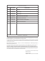
REVISION RECORD
Edition
Date published
Revised contents
01
June, 1994
02
August, 1994
Contents revised
03
Janualy, 1995
Contents revised
04
April, 1995
05
September, 1995
06
January, 1996
Appendix C, Declaration of Conformity added
07
August, 1996
Declaration of Conformity revised
First edition
Pick Roller replacement procedure added
Pad replacement procedure added
Specification No.: C150-E009-07EN
This digital apparatus does not exceed the Class A limit for radio noise emissions from digital apparatus set out in the Radio
interference Regulations of the Canadian Department of Communications.
Le présent appareil numérique n’ément pas de bruits radioélectriques dépassant les limites applicables aux appareils
numériques de la classe A prescridtes dans le Réglesment sur le brouillage radioélectrique édicté par le ministere des
Communications du Canada.
Maschinenlärmlnformationsverordnung 3. GSGV, 18.01.1991:Der arbeisplatzbezogene Schalldruckpegel beträgt 70
dB(A)oder weniger gemäß ISO 7779.
This equipment has been tested and found to comply with the limits for a Class A digital device, pursuant to Part 15 of
the FCC Rules. These limits are designed to provide reasonable protection against harmful interference when the
equipment is operated in a commercial environment. This equipment generates, uses, and can radiate radio frequency
energy and, if not installed and used in accordance with the instruction manual, may cause harmful interference to radio
communications. Operation of this equipment in a residential area is likely to cause harmful interference in which case
the user will be required to correct the interference at his own expense.
The contents of this manual is subject to change
without prior notice.
All Rights Reserved,
Copyright 1994, 1995, 1996 FUJITSU LIMITED
i
Conventions
Special information, such as warnings, cautions are indicated as
follows:
WARNING
A WARNING indicates that personal injury may result if you do not
follow a procedure correctly.
CAUTION
A CAUTION indicates that damage to the scanner may result if you
do not follow a procedure correctly.
NOTICE
A NOTICE provides “how-to” tips or suggestions to help you perform
a procedure correctly. NOTEs are particularly useful for first-time
users.
ii
CONTENTS
page
CHAPTER 1
PREFACE .....................................................................................................1-1
CHAPTER 2
COMPONENTS ............................................................................................2-1
2.1
Checking the Components ..........................................................................................2-1
2.2
Part Names and Functions ............................................................................................2-2
2.3
2.2.1
Exterior view of image scanner ...........................................................................2-2
2.2.2
Functions of each part ..........................................................................................2-3
Indication Panel Functions (standard model)...............................................................2-4
2.3.1
2.4
Indicators .............................................................................................................2-4
Operator Panel Functions (LCD model) ......................................................................2-4
2.4.1
Indicators .............................................................................................................2-5
2.4.2
Buttons and liquid crystal display screen ............................................................2-5
2.4.3
Liquid crystal display screen ...............................................................................2-6
2.4.4
Messages ............................................................................................................2-11
CHAPTER 3
INSTALLATION AND CONNECTIONS .................................................3-1
3.1
Precautions ...................................................................................................................3-1
3.2
Removing the Carrier Fixing Bracket ..........................................................................3-2
3.3
Connections ..................................................................................................................3-3
3.4
Mounting the Stacker ...................................................................................................3-5
3.5
SCSI -ID Setting ..........................................................................................................3-6
CHAPTER 4
OPERATIONS ..............................................................................................4-1
4.1
Turning on the Power ...................................................................................................4-1
4.2
Reading a Document in Flatbed Mode ........................................................................4-2
4.3
4.2.1
Reading a standard-size document ......................................................................4-2
4.2.2
Reading a page from a thick book .......................................................................4-3
4.2.3
Reading a document larger than the document board ..........................................4-4
Reading Documents in ADF Mode ..............................................................................4-5
iii
CHAPTER 5
MAINTENANCE ..........................................................................................5-1
5.1
Removing Jammed Documents ...................................................................................5-1
5.2
Notes on Daily Use ......................................................................................................5-2
5.3
Cleaning .......................................................................................................................5-2
5.4
5.3.1
Cleaning the document cover, document holding pad, and document bed .........5-2
5.3.2
Cleaning the ADF ................................................................................................5-3
Consumables/Periodical replacement parts .................................................................5-4
5.4.1
Parts number and replacement cycle ...................................................................5-4
5.4.2
Replacing pad ASY .............................................................................................5-4
5.4.3
Replacing pick roller ............................................................................................5-5
CHAPTER 6
TROUBLESHOOTING ...............................................................................6-1
APPENDIX A ..........................................................................................................................A-1
A.1 Installation Specifications ...........................................................................................A-1
A.2 External Dimensions ...................................................................................................A-2
APPENDIX B ..........................................................................................................................B-1
B.1 Test mode for maintenance .........................................................................................B-1
APPENDIX C ..........................................................................................................................C-1
C.1 Option ..........................................................................................................................C-1
C.2 IPC-2/CMP-2 option board installation ......................................................................C-1
iv
FIGURES
page
2.1
Received components ..................................................................................................2-1
2.2
M3096EX/GX parts names ..........................................................................................2-2
2.3
M3096EX/GX Indication panel ...................................................................................2-4
2.4
M3096EX (LCD model) operator panel ......................................................................2-4
3.1
SCSI-ID setting ............................................................................................................3-6
4.1
Flatbed reading .............................................................................................................4-3
4.2
Removing the document cover.....................................................................................4-4
4.3
ADF paper chute setting ..............................................................................................4-7
4.4
Loading the document ..................................................................................................4-9
5.1
Removing jammed documents .....................................................................................5-1
5.2
Cleaning the document cover, document holding pad, and document bed ..................5-2
5.3
Cleaning the ADF ........................................................................................................5-3
5.4
Pick Roller replacement ...............................................................................................5-5
5.5
Move the Retaining spring ...........................................................................................5-6
5.6
Slide the Pick Roller ....................................................................................................5-6
5.7
Remove the Pick Roller ...............................................................................................5-6
A.1 External dimensions ....................................................................................................A-2
v
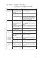
TABLES
page
1.1
The differences between the M3096EX and the M3096GX ........................................1-1
3.1
SCSI-ID setting ............................................................................................................3-6
6.1
Check items ..................................................................................................................6-1
A.1 Installation specifications ............................................................................................A-1
B.1 LED at an error ............................................................................................................B-2
vi
CHAPTER 1 PREFACE
This manual describes how to operate the M3096EX and M3096GX image scanners. An image
scanner optically reads image information from a document and outputs the information to the
host system. The differences between the M3096EX and the M3096GX image scanners are
listed in table 1.1.
Table 1.1
Model number
The differences between the M3096EX and the M3096GX
Interface
Shipping
models
Image size
Automatic
document feeder
A3 size or
double-letter
size
Yes
Max. 50 pages
(A4)
M3096EX
LCD model
Standerd model*
RS232C
+
VIDEO
North America
M3096GX
(Standerd
model)
SCSI2
North America
Europe
Europe
*Standerd model is the model which does not have LCD on operator panel.
This manual should be read before operating the image scanner to ensure correct operation.
Note on Copyright Act
This document cannot be reproduced or copied for any use other than private without the
author’s permission.
1–1
This page is intentionally left blank.
1–2
CHAPTER 2 COMPONENTS
2.1 Checking the Components
2.2 Part Names and Functions
2.3 Indication Panel Functions
2.4 Operator Panel Functions
After unpacking image scanner, confirm that all the components have been received. This
section describes the components of the image scanner and their functions.
2.1
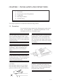
Checking the Components
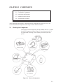
These high precision components must be handled with care. Confirm
that all the components shown in figure 2.1 have been received. If
any component is missing, please contact your local Fujitsu sales
person.
Power cable
for Europe
Image scanner
Power cable for
North America
Terminator
(for M3096GX)
Operator’s Guide
(this manual)
Pads
Inspection
report
One stacker and
two extensions
Figure 2.1 Received components
2–1
2.2
Part Names and Functions
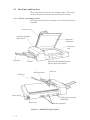
This section shows the exterior view of image scanner. This section
also provides names of each part and describes their functions.
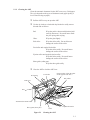
2.2.1 Exterior view of image scanner
The image scanner can read a document of A3 or double-letter size at
maximum.
Document cover
Automatic document
feeder (ADF)
Document
holding pad
Document
bed
Extension
Indication panel (Standerd model)
Operator panel (LCD model)
Stacker
ADF paper chute
ADF lever
Extension
Power switch
Third party slot opening
(M3096EX)
Power inlet
Interface connectors
Figure 2.2 M3096EX/GX parts names
2–2
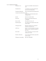
2.2.2 Functions of each part
Document cover:
Closed over and holds a document to be
read.
Document bed:
A document to be read is placed on the
bed also called Flatbed (FB).
Document holding pad:
Presses a document to the document bed.
Automatic document feeder (ADF):
Automatically feeds documents to the
reading position.
Stacker:
Stacks the read documents.
Extension:
Keeps the stacked documents from
overhanging.
Power switch:
Turns the power on or off.
Indication panel:
The indication panel indicates the status
of the scanner.
ADF paper chute:
Holds the documents to be fed by the
automatic document feeder.
ADF lever:
Opens or closes the automatic document
feeder to remove documents jammed in
the feeder.
Power inlet:
To be connected to an AC power outlet
with the power cable.
Interface connectors:
To be connected to the host system with
interface cables.
Third party slot opening:
Reserved. (M3096EX)
2–3
2.3
Indication Panel Functions (standard model)
Power
Read
Check
Indicators
Figure 2.3 M3096EX/GX Indication panel
2.3.1 Indicators
The meaning of each indicator is as follows:
Power indicator (Green):
Lights to indicate the power is on.
Read (reading in progress) indicator (Green) :
Lights to indicate reading is in progress.
Check (device check) indicator (Yellow):
Lights if a device error occurs which may result in a service
call. This indicator blinks if a document is jammed in the
automatic document feeder. This indicator turns off when the
jammed documents are re-moved from the feeder and the
feeder is closed.
This indicator blinks in four seconds period if the ADF cleaning is necessary. (See 5.3.2)
2.4
Operator Panel Functions (LCD model)
The operator panel has indicators and a liquid crystal display screen
for displaying image scanner status. The operator panel also has
operation buttons.
Liquid crystal display screen
Buttons
Mode 1
ADF
Size
Density Resolution
Stop
Halftone
Start
Power
Ready
Mode 2
Landscape
Document
Check
Indicators
Figure 2.4 M3096EX (LCD model) operator panel
2–4
2.4.1 Indicators
The meaning of each indicator is as follows:
Power indicator (Green):
Lights to indicate the power is on.
Read indicator (Green) :
In manual mode, when this lamp is lit, it indicates that the start
switch is enabled.
Check (device check) indicator (Yellow):
Lights if a device error occurs which may result in a service
call. This indicator blinks if a document is jammed in the
automatic document feeder. This indicator turns off when the
jammed documents are removed from the feeder and the feeder
is closed.
2.4.2 Buttons and liquid crystal display screen
The function of each button is as follows:
Start button:
Read operation can be started in either manual or automatic
mode. To start reading in manual mode, press this button while
the ready indicator is lit.
• Manual mode: Reading is started by the start button.
• Automatic mode: Reading is started by a command from
the host system.
Stop button:
This button is effective regardless of whether the scanner is in
manual or automatic mode. Press this button to stop the read
operation. When this button is pressed, the image scanner
operates as follows:
• Reading in flatbed mode: Reading is immediately stopped.
• Reading in ADF mode: Reading is immediately stopped
and documents being fed are ejected to the stacker.
After cleaning a jam, press the stop button to clear the
“Paper Jam” message displayed on the screen. The
ready screen will then be displayed to indicate that the
scanner is ready to read.
2–5
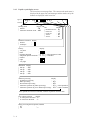
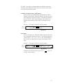
2.4.3 Liquid crystal display screen
The screen has two message lines. The current read mode status is
displayed in the upper line, and messages and the modes set by the
buttons are displayed in the lower line.
Upper line
ADF
A 4
4 0 0
L . >
Lower line
Reading mode
Display
: FB
Flatbed
Automatic document feeder : ADF
Size
Display
Double-letter size : DL
: LT
Letter size
: LG
Legal size
: A3
A3 size
: A4
A4 size
Doument orientation Display
Portrait:
:
Landscape:
:
Density
Very dark
Dark
Dynamic threshold
Simplified dynamic threshold
Normal
Light
Very light
Display
:
:
: A T 1
: A T 2
:
:
:
optional PC board
} Ifis the
installed
Resolution Display
400 dpi
: 400
300 dpi
: 300
240 dpi
: 240
200 dpi
: 200
Halftone processing
No halftone processing
Dither processing
Error diffusion processing
Automatic separation (by dither processing)
Automatic separation (by error diffusion processing)
Display
:
: HT1
: HT2
: LP1 If the optional PC
: LP2 board is installed
If the optional PC board is not installed, automatic separation cannot be done.
Line or photo selection
Display
To read a photo document : P.
To read a line document : L.
Image processing board (optional) installed
No
:
Yes
: >
2–6
The ADF, size, density, resolution, landscape, half-tone, document,
and mode 1 and 2 buttons described below are effective unless otherwise specified by the host system.
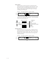
Automatic document feeder (ADF) button:
Selects whether to feed documents automatically by ADF or
manually on the flatbed. When this button is pressed, the lower
line is displayed as shown in Screen 1. Each time this button is
pressed, “FB” or “ADF” starts blinking in turn, and the read
operation status displayed in the upper line changes accordingly.
Screen 1 — The upper line shows a typical example.
Upper line
Lower line
ADF
A 4
Re a d : FB
4 0 0
ADF
L . >
Blinking
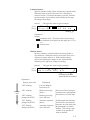
Size button:
Selects a document size. When this button is pressed, the lower
line is displayed as shown in Screen 2. Each time this button is
pressed, “DLT”, “LT”, “LG”, “A3”, or “A4” starts blinking in
turn, and the size displayed on the upper line changes accordingly.
Screen 2 — The upper line shows a typical example.
Upper line
Lower line
ADF LG
S i z e : DL T
L T
4 0 0
LG A 3
L . >
A 4
Blinking
If the direction indicated on the upper line is “
or “A4” can be selected.
”, only “LT”
2–7
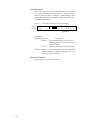
Density button:
Selects a density for the read operation. When this button is
pressed, the lower line is displayed as shown in Screen 3. Each
time this switch is pressed, the blinking part in the lower line
changes, and the density indicated on the upper line changes
according to the blinking part.
Screen 3 — The upper line shows a typical example.
Upper line
Lower line
ADF LG
De n . :
4 0 0
P . >
AT ( A u t o ) 1
Blinking
The lower line is displayed as shown below. (See the beginning
of this section for the upper line.)
Display (lower line)
Blinking If the
AT ( Au t o ) 1
order optional
PC board
AT ( Au t o ) 2
is installed:
{
Explanation
Very dark
Dark
Dynamic threshold
Simplified dynamic threshold
Normal
Light
Very light
Resolution button:
Selects a resolution for the read operation. When this button is
pressed, the lower line is displayed as shown in Screen 4. Each
time this button is pressed, “400”, “300”, “240”, or “200” starts
blinking in turn, and the resolution indicated on the upper line
changes accordingly.
Screen 4 — The upper line shows a typical example.
Upper line
Lower line
ADF LG
Re s . : 4 0 0
4 0 0
3 0 0 2 4 0
Blinking
2–8
P . >
2 0 0
Landscape button:
Specifies whether reading is done in landscape or portrait mode.
When this button is pressed, the lower line is displayed as
shown in Screen 5. Each time this button is pressed, the blinking part changes in turn, and the mode indicated on the upper
line changes accordingly.
Screen 5 — The upper line shows a typical example.
Upper line
Lower line
ADF L T
S i z e : DL T
L T
4 0 0
LG A 3
P . >
A 4
Blinking
Explanation:
Display
: Landscape mode. This mode can be selected only if
the document size displayed on the upper line is LT or
A4.
: Portrait mode.
Halftone button:
Specifies whether to perform halftone processing (dither or
error diffusion). When this button is pressed, the lower line is
displayed as shown in Screen 6. Each time this button is
pressed, the blinking part changes in turn, and the halftone
indication on the upper line changes accordingly.
Screen 6 — The upper line shows a typical example.
Upper line
Lower line
ADF LG
4 0 0 HT 1
Ha l f t o n e : OF F HT 1
L . >
Blinking
Not displayed unless the
optional PC board is installed.
Explanation:
Display (lower line)
Blinking
order
Explanation
“OFF” blinking
: Line Art (Halftone
Processing off)
“HT1” blinking
: Halftone processing
(dither)
“HT2” blinking
(changed from HT1)
: Halftone processing
(error diffusion)
“LP1” blinking
(changed from HT2)
: Automatic separation If photographs and characters
are mixed in a document, the
(dither)
characters are read clearly and
: Automatic separation
the photographs are read in
(error diffusion)
halftone. This setting is only
available if the optional PC
board is installed.
“LP2” blinking
(changed from LP1)
Select one of these settings to
read data such as photographs,
illustrations, or colored maps.
2–9
Document button:
Selects the type of document. When this button is pressed, the
lower line is displayed as shown in Screen 7. Each time this
button is pressed, “LINE” or “PHOTO” starts blinking in turn,
and the document selection indication displayed on the upper
line changes accordingly.
Screen 7 — The upper line shows a typical example.
Upper line
Lower line
ADF LG
3 0 0 HT 1 P . >
DOC . :
L . ( L i n e )
P . ( P h o t o )
Blinking
Explanation:
Display (lower line)
Explanation
P.(Photo) : For light adjustment or when there is a
dark background color on the document,
select P. (Photo).
L.(Line) : Select this setting to read line drawings.
NOTICE :When L. (Line) is selected, the top 3-mm part of the
read area should be left blank (grounding color) by
specifying a drop-out color.
Mode 1 and 2 button:
These buttons are used for maintenance.
2 – 10
2.4.4
Messages
Error messages (temporary errors)
If a temporary error occurs in the scanner, one of the following messages is displayed.
P a p e r
Emp t y
This message is displayed if there is no more paper on the
ADF paper chute during a read operation in ADF mode.
Fill the ADF paper chute with paper. To enable the read
operation, press the stop button.
P a p e r
J am
This message is displayed if a document is jammed in the
ADF. See section 5.1 for removing jammed documents.
ADF
–
Co v e r
Op e n
This message is displayed if the ADF is not closed
completely. Close the ADF completely, and enable the
read operation.
2 – 11
Error messages (device errors)
One of the following messages is displayed if an error occurs in the
scanner. If one of the following error messages is displayed, turn the
power off and then on again. If the same message is displayed,
contact your service representative.
Op t i c a l
A l a rm
Me c h a n i c a l
Fu s e
Fu s e
A l a rm
A l a rm
–
A l a rm
–
FB
L amp
Mo t o r
Operation status messages
Operation status is displayed as shown by the following messages:
Wa r m i n g
The power
power isis on.
on.
The
–
up
Now ! !
Now Read i ng !
Reading isis inin progress.
progress.
Reading
ADF
LG
4 0 0 HT2 L . >
Ready
The scanner
scanner isis ready
ready for
for operation
operation inin the
the manual
manual mode.
mode.
The
Press
Press the
the start
start button
button toto start
start the
the read
read operation.
operation.
Please clean Pick–roller
2 – 12
CHAPTER 3 INSTALLATION AND CONNECTIONS
3.1
3.2
3.3
3.4
3.5
Precautions
Removing the Carrier Fixing Bracket
Connections
Mounting the Stacker
SCSI-ID Setting
This chapter explains how to install and connect the image scanner.
3.1
Precautions
Do not install the image scanner in the following places and environments. See the appendix A.1 “Installation Specifications” for the
information such as size of installation space.
Place the scanner away from electrical noise
sources and strong magnetic fields. If the
image scanner is used near an air conditioner,
copying machine, or TV set, the scanner may
operate incorrectly.
Do not install the scanner in a humid, dusty,
or damp places. These enviroments may
shorten scaner life or cause hardware failures. Do not place the image scanner where
liquid spills may occur. Place it on a flat and
even surface.
Keep the scanner out of the sun and away
from heaters. These environments may
shorten scanner life or cause hardware
failures.
Do not install the scanner in a place where
vibrations may occur. This environment may
cause hardware failures or may cause the
scanner to operate incorrectly.
CAUTION
Place the image scanner on a level surface.
Place the image scanner so that the rubber
pads are secured on a flat and solid desktop.
Be aware of static electricity. If static
electricity is generated, the scanner may
operate incorrectly. Be sure that the flooring
and the desk are made of materials that do
not generate static electricity.
3–1
3.2
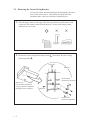
Removing the Carrier Fixing Bracket
To keep the scanner from being damaged during shipping, the carrier
unit is fixed with a bracket. After placing the carrier unit at the
installation place, remove this bracket as explained below.
①
Place the image scanner on the edge of the desk top so that the left side (where ADF
is placed) of the scanner extends from the desk top. Do not set the image scanner
upside down or on its side.
×
②
×
Remove the carrier fixing bracket from position A. Then install the carrier fixing
bracket at position B.
Front side
Enlarged
Carier bracket
(Position for operation)
Bottom view
Carier bracket (Position for
storage, position for shipment)
Enlarged section A enlarged
B
ADF side
A
Carier bracket
(Position for shipment)
3–2
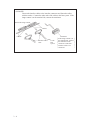
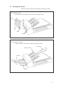
3.3
Connections
Connect the image scanner using the following procedure.
①
Set the power switch to off.
Power switch
②
Connect the power cable.
Connect the power cable to the power inlet on the back of the image scanner.
Connect the other end of the power cable to a power outlet.
Power outlet
for North America
Power inlet
Power cable
for Europe
③
Connect the interface cables (for M3096EX).
Connect the interface cables to the interface connectors and fasten the cables
with catches and screws as shown below.
Connect the other end of each interface cable to the host computer.
Back of the image scanner
Catches
Interface cable for video
Interface cable for RS232C
Screws
To the host system
3–3
(M3096GX)
Connect the interface cables to the interface connectors and fasten the cables
with the catches. Connect the other ends of the cables to the host system. If the
image scanner is at the terminal side, connect the terminator.
Back of the image scanner
Catches
Catches
Interface cables
3–4
To the
host
system
Terminator
If the image scanner is at
the terminal side, connect
the terminator to the
connector to which an
interface cable is not
connected.
3.4
Mounting the Stacker
Mount the stacker and extensions using the following procedure.
①
Mount the stacker.
Hook the pins on the stacker to the claws on the image scanner.
Stacker
Pin
Claw
②
Mount the extensions.
Mount extensions to the stacker and to the ADF paper chute.
Extension
ADF paper chute
Extension
Stacker
3–5
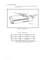
3.5 SCSI-ID Setting
Use the address switches to set the device address. After the setting
turn the scanner on.
Address switch
Figure 3.1 SCSI-ID setting
Table 3.1 SCSI-ID setting
ID
Contents
0 to 7
Available
8, 9
No Operation
* When the scanner is terminated device, the termination connector
must be connected on one side of the connectors.
3–6
CHAPTER 4 OPERATIONS
4.1 Turning on the Power
4.2 Reading a Document in Flatbed Mode
4.3 Reading Documents in ADF Mode
Documents can be read in the flatbed mode or automatic document feeder (ADF) mode. In the
flat-bed mode, each document is placed on the document bed and is read one by one. In ADF
mode, documents are fed and read automatically.
This section explains how to turn on the power and how to read documents.
4.1
Turning on the Power
This section explains how to turn on the power.
Press "I" on the power switch. When the power is turned on, the
power indicator is lit.
Power indicator
Press "0" on the power switch to turn off the power.
Power switch
Power OFF
Power ON
4–1
4.2
Reading a Document in Flatbed Mode
This section explains how to read a document placed on the document
bed.
4.2.1 Reading a standard-size document
If the size of the document is smaller than the document bed, read the
document using the following procedure:
4–2
①
Open the document cover.
②
Place the document face down on the document board. Correct
any curled or folded parts of the document.
③
Position the long side (in landscape mode) or the short side (in
portrait mode) of the document to the left side of the document
bed.
④
Position the left top of the document to the reference mark. If the
document is not placed correctly, reading cannot be done correctly.
⑤
Close the document cover slowly. If the document cover is
closed too quickly, the document may move.
⑥
Start the read operation. Do not press on or open the document
cover during the read operation.
⑦
After reading, open the document cover to remove the document.
Document cover
Reference mark
Document
Indication panel
Document bed
Figure 4.1 Flatbed reading
3
Portrait mode
Short side
Long side
Landscape mode
Document bed
3
Document
4.2.2 Reading a page from a thick book
To read a page from a thick book, remember the following points:
①
Do not close the document cover forcibly. Keep the cover open
for reading.
②
Any document parts that are not in contact with the glass will not
be read correctly.
③
Do not move the document during the read operation.
4–3
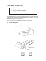
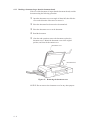
4.2.3 Reading a document larger than the document board
If the size of the document is larger than the document board, read the
document using the following procedure:
①
Open the document cover at an angle of about 80°, then slide the
cover to the direction of the arrow to remove it.
②
Place the document face down on the document bed.
③
Place the document cover over the document.
④
Read the document.
⑤
After the read operation, remove the document, replace the
document cover. Mount the document cover to the original
position, and close the document cover.
Document cover
80°
Document bed
Figure 4.2 Removing the document cover
NOTICE: Do not remove the document cover for any other purpose.
4–4
4.3 Reading Documents in ADF Mode
This section explains how to read documents using the automatic
document feeder. If the following steps are not closely followed, a
feed error may occur.
①
Check the documents as follows:
(a) Paper quality
• Wood-free paper.
• PPC paper; Specified by XEROX Corporation.
(b) Paper weight
• 13.91bs to 27.81bs
(c) Paper size
• Letter, Double Letter, Legal, A3, A4, A5, B4, B5
(d) Items to avoid
• The following documents may be hard to read by ADF. Before
you start the large quantity reading, check that the document is
read appropriately. If the reading is not appropriate, read them
by flatbet.
– Paper with a clip or staple.
– Paper that has ink which is not dry.
– Paper thickness is not constant, such as an envelope.
– Paper that has large rumples or curl. (See NOTICE)
– Paper that has folds or tears.
– Tracing paper.
– Coating paper.
– Carbon paper.
– Paper that is smaller than A5 size or larger than A3 width.
– Items other than paper, such as clothes, metal sheet, or OHP
film.
– Photographic paper.
– Paper that has perforations on its side.
– Paper that has a shape other than square.
– Paper that is very thin.
NOTICE : The important document which shall not be torn must be
read by flatbet.
NOTICE : Carbonless papers have the chemical composition which
damages the pad and pickroller. Therefore, note the following remarks.
Cleaning : If the miss pick occurs frequently, clean the pad
and pickroller in accordance with the section
5.3.2.
Replacement of parts : The life of the pad and the pickroller
may be shorter than the case that PPC document
is fed. Replacement cycle of the pad and the
pickroller may be 100,000 sheets or more if the
paper quality is good and cleaning is done well.
Before you start the large quantity reading,
check the replacement cycle of them and prepare
pads and pickrollers.
4–5
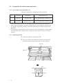
NOTICE: Paper should be straightened to fit the condition below.
More than
30 mm
Feed direction
Less than
3 mm
Top of the paper
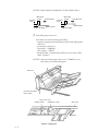
②
Less than
5 mm
Read surface
More than
30 mm
Feed direction
Read surface
Top of the paper
Switch the paper select lever.
Switch the lever in the following procedures:
• Open the automatic document feeder (ADF) while lifting up the
ADF lever.
• Set the paper select lever.
Plain paper: “NORMAL”
Heavy paper: “THICK”
• Reset the ADF. (Check that the ADF lever is set at the “NORMAL” position.)
NOTICE: Always reset the paper select lever to “NORMAL” position, unless you feed the thick paper.
ADF lever
Automatic document
feeder (ADF)
Paper select lever
(THICK mode)
(NORMAL mode)
Section A enlargerd
4–6
ADF frame
③
Pull up the ADF paper chute as follows:
• Hold the document cover with one hand and pull up the ADF
paper chute with the other hand to set the shaft in position B.
ADF paper chute
Document cover
ADF paper chute
Rotation direction
Shaft
Position for storage
position A
Position for operation
position B
Figure 4.3 ADF paper chute setting
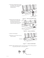
④
Fan the documents as follows:
• Take a 15 to 20 mm thickness of documents. Lightly hold both
ends with both hands. Bend the documents into an arch as
shown below.
• Then hold the documents tightly with both hands, and
straighten the documents. The center of documents swell and
air is introduced between the documents.
• Repeat this operation two or three times.
• Turn the documents 90°, and repeat the operation again.
15 to 20 mm
4–7
⑤
Take documents to be placed in the ADF paper chute. The
thickness of the documents to be placed in the ADF paper chute is
limited depending on the size of the documents as follows:
A4 or letter size or smaller: 4 mm or less
Size larger than A4:
2 mm or less
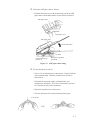
⑥
Angling the documents
Angle the document edges as follows:
• Place the documents face down with the top to the left as shown
in A. The long side is the top for landscape mode and the short
side is the top for portrait mode.
• Lift the documents holding the both ends with both hands.
• Hold the documents tightly with your left hand and bend the
documents as shown in B.
• Grip tightly with your right hand, loosen the grip of your left
hand, and straighten the documents as shown in C.
• Repeat these operations until the top is angled 20° or less as
shown in D.
Top
A
(For portrait mode)
B
D
20° or less
C
4–8
⑦
Open the right and left guides of the ADF paper chute about 5
mm wider than the document width.
⑧
Place the documents face down onto the ADF paper chute with
the top edges facing the automatic feeder hole.
⑨
Adjust the guides to the document sides. Skewing may occur if
there is a gap between the guides and documents.
⑩
Slide the documents down until they touch the far end of the
automatic feeder opening. If the documents hit the far end hard,
two or more pages may be fed at once. Make sure that the upper
end of documents are not turned.
11
Start the read operation. If a wrong document size or mode
(portrait or landscape) is selected, the document may not be read
entirely.
NOTICE:
Unless 3 mm of the leading edge of forms are not white or dropout color, set the document type to “Photo.”
12
After reading, remove the documents from the stacker.
Guide
Automatic document feeder
Documents
ADF paper chute
Guide lever
Guide
Figure 4.4 Loading the document
Landscape
Automatic document feeder
Long side
Short side
Portrait
ADF paper chute
Documents
4–9
This page is intentionally left blank.
4 – 10
CHAPTER 5 MAINTENANCE
5.1 Removing Jammed Documents
5.2 Notes on Daily Use
5.3 Cleaning
5.4 Consumables/Periodical replacement parts
This section explains how to remove jammed documents, and provides notes on daily use and
cleaning.
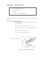
5.1
Removing Jammed Documents
If documents jam while being fed by the ADF, remove the jammed
documents as follows:
①
Remove the documents from the ADF paper chute.
②
Pulling up the ADF lever, open the automatic document feeder.
③
Remove the jammed documents.
④
Close the ADF until the ADF lever locks.
ADF lever
Automatic document feeder (ADF)
Figure 5.1 Removing jammed documents
5–1
5.2
Notes on Daily Use
Note the following points on daily use:
NOTICE
• Do not look directly at the light source during the read operation.
Keep the document cover in place.
NOTICE
• See Section 5.3 “Cleaning”, to clean the document cover, document
holding pad, document bed, and the automatic document feeder.
Especially, clean the automatic document feeder (ADF) periodically.
For the cleaning cycle, see Section 5.3.2, “Cleaning the ADF.”
5.3
Cleaning
This section explains how to clean the image scanner.
5.3.1 Cleaning the document cover, document holding pad, and document bed
• Use a dry cloth or a cloth with a neutral cleanser to remove dirt from
the document cover, document holding pad, and document bed. Do
not use organic solvents such as a thinner.
• Make sure that no liquid enters the scanner from the edges of the
document bed glass.
Document cover
Cloth
Document holding pad
Document bed
Neutral cleanser
Thinner
Figure 5.2 Cleaning the document cover, document holding pad, and document bed
5–2
5.3.2 Cleaning the ADF
Clean the automatic document feeder (ADF) once every 5,000 pages.
The cycle depends on the types of documents used (paper quality, a
level of toner fusing on paper).
①
Pull the ADF lever up to open the ADF.
②
Use the dry cloth or a cloth with ethyl alcohol to softly remove
dirt and dust as follows.
Pad:
Wipe the pad in a downward direction (indicated by the arrow). Be careful not to hook
the pick spring when wiping.
Glass:
Wipe the glass lightly.
Pick roller :
Wipe the roller softly. Be careful not to
damage the surface of the roller.
Feed roller and coupled feed roller:
Wipe the rollers softly. Be careful not to
damage the surface of the rollers.
Ejection roller and coupled ejection roller:
Wipe the rollers softly. Be careful not to
damage the surface of the rollers.
Sheet guide (white part):
Wipe the sheet guide softly.
③
Close the ADF to lock the ADF lever.
Pick spring
Feed roller
Ejection roller (Clean the roller
on the opposite side also.)
Pick rollers
ADF lever
Pad
Automatic document feeder
Sheet guide (white part)
Figure 5.3
Coupled feed roller
Glass
Cleaning the ADF
5–3
5.4 Consumables/Periodical replacement parts
5.4.1
Parts number and replacement cycle
Customer is responsible to change these items periodically.
No.
Part name
Part number
Replacement cycle
1
Pad ASY
PA02201-0020
Every 100,000 pages or annually (*1)
2
Pick roller
PA02201-0025 (*2)
Every 200,000 pages or annually (*1)
*1: These replacement cycle may vary by the paper quality and cleaning result. When PPC
paper is used, replacement cycle may be 300,000 sheets or more by good cleaning. Before
you start the large quantity reading, evaluate the replacement cycle and prepare pads and
pickrollers.
*2: This part may not be provided in some countries due to the conformability of safety regulation. Before the order of the pick roller, contact your sales agent or Fujitsu service representative.
5.4.2
Replacing pad ASY
①
Lift up the ADF lever and open the ADF.
②
Insert a coin in the slot or hold the both sides of the pad ASY,
then slide it to the direction of the arrow to remove the pad.
Pad ASY
ADF lever
Slot
5–4
③
Insert the pad assembly into the ADF frame hole (the bigger one),
slide the assembly to the direction of the arrow until it clicks.
ADF frame
Pad assy
NOTICE : Set the paper select lever to "N", before removing pad ASY
(See Section 4.3).
NOTICE : Pad can be replaced by aligning the holes of the pad with
the pins of the pad holder.
Pad holder
Pad
Pick spring
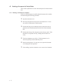
5.4.3
Replacing pick roller
Replace the pickroller as follows.
Thumb Screw
(a) Pull the cap up to open the ADF
unit.
Cap
(b) Remove two thumb screws shown
in Figure 5.4. And remove the
Guide A.
Guide A
Thumb Screw
Figure 5.4
Pick Roller replacement
5–5
(c) Pinch the retaining spring and slide
it toward the roller. Free bearing A
from the bracket by sliding it
toward the roller.
Bearing A
Retaining spring
Figure 5.5
Move the Retaining spring
(d) Slide the pick roller shaft in the
direction of arrow B and remove
the shaft from bearing B. The
roller shaft can then be lifted and
removed as shown in Figure 5.7.
A
B
Bearing A
Figure 5.6
Slide the Pick Roller
(e) Remove the bearing B.
(f) Mount the new pick roller in reverse
order of removal.
Bearing B
Figure 5.7
Remove the Pick Roller
NOTICE: When mounting the Guide A, note that the hooks of the retaining spring are
not pressed by the Guide A. (See figure bellow)
Guide A
Retaining spring
5–6
CHAPTER 6 TROUBLESHOOTING
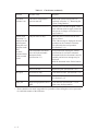
If a problem occurs, use Table 6.1 to resolve the problem.
Table 6.1
Check items
Problem
Possible cause
Response
No power
The power switch was not
turned on.
Press the power switch.
The power cable was not
connected correctly.
Connect the power cable correctly.
——————————
Read operation
does not start.
Turn off the power once and make an
attempt to turn on the power again. If the
power is not turned on, contact your
Fujitsu service representative.*
The documents were not
placed on the ADF correctly.
Insert the first a few pages into the slot.
The ADF was not closed
completely.
Make sure that the ADF is closed completely.
The interface cables were not
connected correctly.
Connect the interface cables correctly.
Terminator was not connected. (M3096GX)
Connect the terminator.
Pictures and
photographs are
not read correctly.
Halftone processing was not
selected.
Select a halftone mode from the host
system.
The document bed, document holding pad, or inside
ADF is dirty.
Clean the dirty parts as explained in
Section 5.3, “Cleaning.”
Characters and
lines are not
read correctly.
Simple binarization was not
done.
Select a binarization mode from the host
computer.
The document bed, document holding pad, or the
inside of the ADF is dirty.
Clean the dirty parts as explained in
Section 5.3, “Cleaning.”
Image is distorted or unclear.
The document was moved
during the read operation.
Keep the document cover closed during
reading so that the document will not be
moved.
The document was not in
contact with the glass.
Adjust the document so that it is in
contact with the glass.
6–1
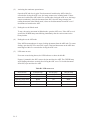
Table 6.1
Check items (continued)
Problem
Possible cause
Response
The check
indicator is on.
The carrier fixing bracket
was not removed.
Remove the carrier fixing bracket as
explained in Section 3.2, “Removing the
Carrier Fixing Bracket.”
——————————
Turn the power off then on again. If the
check indicator turns on again, contact the
sales person in charge or a Fujitsu service
representative.*
“Please clean
Pick-roller” is
displayed on the
operator panel
during the read
operation in the
ADF.
Or check
indicator blinks
at four seconds
period.
The pick roller is dirty.
When the power is turned off, the message is cleared.
Even if the message is displayed, the read
operation can be continued. Clean the
pick roller after the read operation.
(See Section 5.3.2.)
The unallowable document
was read in the automatic
document feeder.
(See Section 4.3.)
If a document not meeting the scanner
specifications is read in the automatic
document feeder, the document is not fed
smoothly and an error message may be
displayed.
Read the document in the flat bed station.
Paper double feed
Pad is dirty.
Clean the Pad. (See Section 5.3.2)
Pad is worn out.
Replace the pad. (See Section 5.4.2)
Pick roller is dirty.
Clean the Pick roller. (See Section 5.3.2.)
Pick roller is worn out.
Replace the Pick roller.
(See Section 5.4.3)
Some foreign particles are in
ADF.
Clean the ADF (See Section 5.3.2) or
remove any foreign particles.
Miss pick
Paper jam
* Please chack the test mode in appendix B, if possible, before calling the service representative and inform status of the indicators.
6–2
APPENDIX A
A.1
Installation Specifications
Table A.1
Installation specifications
Item
External dimensions (mm)
Weight (kg)
Input power
Specification
Width
Depth
Height
696
497
173
17.5
Voltage
100 to 120 VAC, 200 to 240 VAC
Number of phases
Single-phase
Frequency
50/60 Hz
Power
100 VA
Temperature and
humidity allowed
ranges
Operation
Idle
Temperature
5 to 35°C
–20 to 60°C
Humidity
20 to 80%
8 to 95%
A–1
External Dimensions
173
497
A.2
696
(Unit: mm)
Figure A.1
A–2
External dimensions
APPENDIX B
B.1
Test mode for maintenance
CAUTION: Please follow the procedure here or the offset data may be changed incorrectly. If the scanner does not react as the procedure below, turn off the
scanner and start from the beginning.
(1)
Activating a test mode
Open the ADF cover and set the sensors to the following state before turning on the
image scanner. The image scanner can be placed in the maintenance mode by pulling out
the empty sensor lever and setting the A4 size sensor lever to down position (do not
change the setting of other paper size sensors) with the ADF cover fully opened (see
Figure below). If the image scanner is placed in the maintenance mode, the POWER lamp
blinks. If the POWER lamp does not blink, turn off the power and try again. Then close
the ADF.
(Setting of the ADF sensors for maintenance mode)
- A4 size sensor: DOWN
- Empty sensor: UP
Empty sensor
A4 size sensor
UP
DOWN
OMR sensor
Open the ADF cover.
B–1
(2)
Activating the continuous operation test
Open the ADF and close it again. If no document is loaded on the ADF within five
seconds after closing the ADF cover, the image scanner runs in flatbed mode. If documents are loaded on the ADF within five seconds after closing the ADF cover, the image
scanner continuously feeds the document from ADF. Once the image scanner start
reading documents in the flatbed mode, it does not feed documents from ADF even if
documents are loaded on the ADF.
(3)
Ending the test in flatbed mode
To stop the carrier movement in flatbed mode, open the ADF cover. If the ADF cover is
opened, the POWER lamp starts blinking immediately after the carrier returns to the
home position.
(4)
Ending the test in ADF mode
If the ADF document hopper is empty, feeding documents from the ADF ends. To restart
feeding, open the ADF cover and close it again. Then load documents on the ADF document hopper within five seconds after closing the ADF cover.
(5)
LED status on error
If an error occurs during the test, the LED indicates as shown in table B.1.
If paper is jammed in the ADF, remove the jam and close the ADF. The CHECK lamp
stops blinking about three seconds after closing the ADF cover. To feed the document
from ADF, open and close the ADF.
Table B.1 LED at an error
Errors/Alarm
Paper jam
Carrier drive alarm
Optical system alarm
Motor fuse failure
Lamp fuse failure
B–2
POWER lamp
On
Blink
Blink
Blink
Blink
READ lamp
Off
Off
Off
On
On
CHECK lamp
Blink
On
Blink
On
Blink
APPENDIX C
C.1
Option
Name
Specfication
Scanner
feature
IPC-2
CA01952-0191
M3096EX
M3096GX
Image processing
• Automatic separation
• Image emphasis
• Outline extraction
• Mirror image
• Dynamic threshold
• Noise removing
• Smoothing
CMP-2
CA01952-0196
M3096GX
• 4Mbyte memory
• MH/MR/MMR compression
Contact your Fujitsu sales agent for more information
C.2
IPC-2/CMP-2 option board installation
WARING: Follow the outlined procedure to avoid danger from electrical components.
(1)
Verify that the scanner power is turned off.
(2)
Remove the AC cable from the year of the scanner.
(3)
Remove the two screws securing the power supply and the interface PCA assembly. Pul
out the assembly slighly using the tab in the direction shown by the arrow.
CAUTION: Do not pull on the flat cable too strongly or it may be damaged.
screws
flat cable
(inside)
Tab
C–1
(4)
Remove the flat cable connector and detach the power supply and PCA assembly.
Flat cable
Flat cable connector
(5)
Connect the IPC-2 option board connector and tighten the screw.
(6)
Where a CMP-2 is installed, remove the screw from the memory board and detach the
memory board. Connect the CMP-2 option board connector and tighten the screw.
Screw for IPC-2
IPC-2 option board
CMP-2 option board or memory PCA (M3096GX)
(not shown)
Screw for memory or CMP-2 (M3096GX)
(7)
C–2
Attach the power supply and PCA assembly in the reverse order of removal.
Comments concerning this manual can be directed to one of the following addresses:
FUJITSU LIMITED
International Operations
Marunouchi 1-6-1, Chiyoda-ku, Tokyo 100,
JAPAN
TEL: (81-3) 3216-3211
FAX: (81-3) 3213-7174
TLX: J22833
Cable: “FUJITSU LIMITED TOKYO”
FUJITSU COMPUTER PRODUCTS OF
AMERICA, INC.
2904 Orchard Parkway, San Jose.
California 95134-2022, U.S.A.
TEL: 1-408-432-6333
FAX: 1-408-432-3908
FUJITSU CANADA, INC.
2800 Matheson Blvd. East, Mississauga.
Ontario 4X5, CANADA
TEL: 1-905-602-5454
FAX: 1-905-602-5457
FUJITSU DEUTSCHLAND GmbH.
Frankfurter Ring 211,
8000 Munchen 40, F.R, GERMANY
TEL: 49-89-32378-0
FAX: 49-89-32378-100
FUJITSU EUROPE LTD.
2, Longwalk Road, Stockley Park, Uxbridge
Middlesex, UB11 1AB, U.K
TEL: 44-81-573-4444
FAX: 44-81-573-2643
TLX: 263871
FUJITSU NORDIC AB
Kung Hans vag, S-191 76 Sollentuna, SWEDEN
TEL: 46-8-626-6000
FAX: 46-8-626-6711
FUJITSU ITALIA S.p.A.
Via Melchiorre Gioia, No. 8-20124 Milano,
ITALY
TEL: 39-2-63651
FAX: 39-2-6572257
FUJITSU FRANCE S.A.
Batiment Aristote, 17 rue Olof palme
94006 Creteil cedex, FRANCE
TEL: 33-14-513-1616
FAX: 33-14-399-0700
FUJITSU AUSTRALIA LIMITED
475 Victoria Avenue Chatswood.
N.S.W 2067, AUSTRALIA
TEL: 61-2-410-4555
FAX: 61-2-411-8603
FUJITSU HONG KONG Limited
Room 2521, Sum Hung Kai Centre
30 Harbour Road Wanchal, Hong Kong
TEL: 852-827-5780
FAX: 852-827-4724
TLX: 62667
FUJITSU ESPANA, S.A
Edificio torre Europa
Paseo de la Castellana 95 Madrid 28046, SPAIN
TEL: 34-1-581-8400
FAX: 34-1-581-8125
Reader Comment Form
We would appreciate your comments and suggestions for improving this publication.
Publication No.
Rev. Letter Title
How did you use this publication?
Learning
Reference
Installing
Maintaining
Is the material presented effectively?
Sales
Operating
What is your overall rating of this publication?
Very Good
Good
Fair
Poor
Current Date
Fully
Covered
Well
illustrated
Well
Organized
What is your occupation?
Very Poor
Your other comments may be entered here. Please be specific and
give page, paragraph and line number references where applicable.
Your Name & Return Address
Clean