1
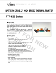
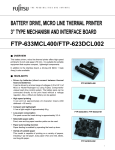
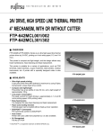
24V, 2" HIGH SPEED THERMAL PRINTER
FTP-627 Series
■ OVERVIEW
The FTP-627 MCL Series consists of 24V drive ultra compact
printers with 2 inch paper widths (58mm), which can print at
high speed. Paper can be easily set by an unique platen
release mechanism.
NO
TF
OR
DE
N
SI
E
GN W
The FTP-627 MCL series can be used for a variety of
applications, such as portable terminals, POS, ticket issuing
terminals, label printers, and measurement and medical
equipment.
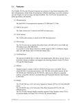
■ HIGHLIGHTS
• Ultra compact
Height 15.5 mm, width 69.6 mm, depth 34.3 mm (MCL002)
• High speed printing
It can print at 60 mm/s (480 dotlines/s) maximum by using
Fujitsu's unique head drive control.
• With Auto Cutter
Two types of compact cutters, a full cut and a partial cut, are
in series.
• High resolution printing / Kanji supported
8 dots/mm of resolution printing is possible.
• Easy paper setting
Our unique platen release mechanism allows a
wide paper route even if the printer is ultra-compact, so
paper can be easily inserted. Auto loading is also available
on MCL001, MCL003 and MCL303 models.
• Two types of paper routes
Front and bottom paper feed.
• Easy mounting
Head, motor, sensor and other component wiring are unified
to one flexible cable, and the mechanism can be secured by
one hook and two screws at two locations, making mounting
easy.
1
FTP-627MCL Series
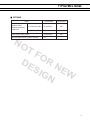
■ PART NUMBERS
Item
Part Number
Printer mechanism
FTP-627MCL001
FTP-627MCL002
FTP-627MCL003
FTP-627MCL004
Mechanism with cutter
FTP-627MCL303 #01 MCL003 with full cut cutter
FTP-627MCL303 #02 MCL003 with partial cut cutter
LSI for driving
FTP-627CU101
ANK only
FTP-627DSL011 (RS232C serial)
FTP-627DCL011 (Centronics)
Kanji
supported
FTP-627DSL112 (RS232C serial with flash),
FTP-627DCL111(Centronics)
NO
Interface
Board
(front paper insertion without head open detection switch
(bottom paper insertion without head open detection switch
(front paper insertion with head open detection switch and knob)
(bottom paper insertion with head open detection switch)
TF
OR
DE
N
SI
E
GN W
■ SPECIFICATIONS
Item
Part number
Printing method
Dot structure
Specifications
FTP-627MCL001/002/003/004/303#01/303#02
Thermal-line dot method
384 dots/line
Dot pitch (Horizontal)
0.125 mm (8 dots/mm)—Dot density
Dot pitch (Vertical)
0.125 mm (8 dots/mm)—Line feed pitch
Effective printing area
48 mm
Number of columns
ANK 32 columns/line (maximum 12x 24 dot font)
Paper width
58 mm +0
-1
Paper thickness
60 to 80 µ m (some paper in this range may not be used because of
paper characteristics)
Printing Speed
Maximum 60mm/sec. (480 dot line/sec.)
Character types
Alphanumeric, katakana:
International and special characters:
JIS Kanji level 1, level 2, non-Kanji
(supported only by FTP-627DSL112, DCL111):
Character, dimensions (H×W), number of
columns
159 types
195 types
about 6800 types
12 × 24 dots, (1.5 × 3.0 mm), 32 columns: alphanumeric, katakana
24 × 24 dots, (3.0 × 3.0 mm), 16 columns: alphanumeric, katakana, Kanji
8 × 16 dots, (1.0 × 2.0 mm), 48 columns: alphanumeric, katakana
16 × 16 dots, (2.0 × 2.0 mm), 24 columns: alphanumeric, katakana, Kanji
2
FTP-627MCL Series
■ SPECIFICATIONS
Item
Interface
Power
supply
Weight
Conforms to RS232C / Centronics
For print head
24 VDC ±5% average current, current approx. 1.1A (25 ˚ C,
Rav=1500) 24V, simultaneously ON, 64 dots)
For motor of printer
24 VDC ±5%, 1A maximum
For motor of cutter
24 VDC ±5%, 1 A maximum
For logic
5 VDC ± 5%, 0.2 A maximum
Printer mechanism
83.5 x 35.7 x 15.5 mm (WxDxH), MCL003 (lever excluded)
NO
Dimensions
Life
Operating
environment
Detection
function
Specification
Mechanism with cutter
83.5 x 43.0 x 26.4mm (WxDxH), (screws and cables are excluded)
Interface board
131 x 89 x 24 mm
Printer mechanism without
cutter
Approximately 55g
Printer mechanism with
cutter
Approximately 120g
Head
Pulse resistance: 100 million pulses/dot (under our standard
conditions). Abrasion resistance: paper traveling distance 50km
(print ratio: 25% or less)
Cutter
300,000 minimum
Operating temperature
+5˚ C to +40˚ C (printing density assurance range, operation is
possible at 0˚ C to +40˚ C)
Operating humidity
20 to 85% RH (no condensation)
Storage temperature
-20˚ C to +60˚ C (paper not included)
Storage humidity
5-95% RH (no condensation)
Head temperature detection
Detected by thermistor
Paper out/mark detection
Detected by photo-interrupter
Head up detection
Detected by slide-switch (003/004/303#1/303#2 only)
TF
OR
DE
N
SI
E
GN W
Recommended thermal sensitive paper
High sensitive paper:
TF50KS-E4 (Nippon Paper)
Standard paper:
F60KS-E (Nippon Paper)
FTP-020PU001, FTP-020P0104 (58mm)
PD150R (Oji Paper)
FTP-020P0701(58mm)
Medium life storage
paper:
TF60KS-F1 (Nippon Paper)
FTP-P0102 (58mm)
PD170R (Oji Paper)
P220VBB-1 (Mitsubishi Paper)
Long life storage paper: PD60R-N (Oji Paper)
AFP-235 (Mitsubishi Paper)
TP50KJ-R (Nippon Paper)
HA220AA (Mitsubishi Paper)
3
FTP-627MCL Series
■ FUNCTION
Item
Item
1.
Test print function
8.
Cutter abnormality detection
2.
Paper out detection
9.
Motor power saving function
3.
Paper near end detection
10.
Mark detection function
4.
Head up detection
11.
MCU operation abnormality detection
5.
Thermal head temperature abnormality
detection
12.
Power ON/OFF sequence protection
Blow-out fuse detection
13.
Motor over-current protection
Head voltage abnormality detection
14.
Hardware timer
6.
7.
NO
TF
OR
DE
N
SI
E
GN W
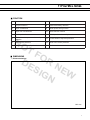
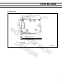
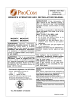
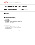
■ DIMENSIONS
1. Printer mechanism
Unit: mm
4
FTP-627MCL Series
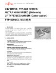
2. Interface board
5.1
130.8
83.8
55.9
6.4
4 - ø 3.6±0.1
88.9
78.7
CN11* CN10
CN1
39.4
39.4
NO
CN8
CN2
CN5**
TF
OR
DE
N
SI
E
GN W
30.5
5.1
91.4
120.7
5.1
Part mounting side
Part solder side
* CN11 used
** CN5 used for paper near end detection
Unit: mm
5
FTP-627MCL Series
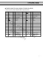
■ PRINTER CONNECTOR (CN8) (FLEXIBLE PT BOARD) PIN ARRAYS
Control circuit side connector: 52030-3010 Molex or equivalent product
No.
Signal
I/O
Contents
No.
Signal
I/O
Contents
1
PHK
—
Photo interrupter (cathode)
2
VSEN
I
Power supply for paper sensor
3
PHE
O
Photo interrupter (emitter)
4
VH
I
Head driving power supply
5
VH
I
Head driving power supply
6
GNC
—
7
GND
Ground for head
8
DIN
I
Data input
NO
—
Ground for head
9
LAT
I
Data latch
10
CLK
I
Clock
11
STB6
I
Enable 6
12
STB5
I
Enable 5
13
STB4
I
Enable 4
14
VDD
I
Logic Power supply
15
STB3
I
Enable 3
16
STB 2
I
Enable 2
17
STB1
I
Enable 1
18
TH
O
Thermistor
19
TH
O
Thermistor
20
GND
—
Ground for head
21
GND
—
Ground for head
22
VH
23
VH
I
Head driving power supply
24
N.C.
—
Open terminal
25
SW1
I
Head open switch*
26
SW2
O
Head open switch*
27
MT/B
I
Stepping motor coil
excitation signal B
28
MT/B
I
Stepping motor coil
excitation signal B
29
MT/A
I
Stepping motor coil
excitation signal A
30
MT/A
I
Stepping motor coil
excitation signal A
TF
OR
DE
N
SI
E
GN W
I
Head driving power supply
* on MCL003 / MCL004/ MCL303#01 and MCL303#02 models
6
FTP-627MCL Series
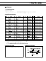
■ INTERFACE
1. Centronics interface
(1) Connector (CN1)
Connector part number
: FCN-605Q030-G/S (Fujitsu Components) or equivalent
Mating connector part number : FCN-607B030-G/D (Fujitsu Components) or equivalent
(2) Connector pin assignment
No.
1
3
5
7
9
Signal
I/O
PRSTB
Contents
No.
Signal
I/O
Contents
I
Data strobe
2
PRSTB-RET
—
Connected to logic GND
PRDT0
I
Data 0
4
PRDT0-RET
—
Connected to logic GND
PRDT1
I
Data 1
6
PRDT1-RET
—
Connected to logic GND
PRDT2
I
Data 2
8
PRDT2-RET
—
Connected to logic GND
NO
TF
OR
DE
N
SI
E
GN W
PRDT3
I
Data 3
10
PRDT3-RET
—
Connected to logic GND
11
PRDT4
I
Data 4
12
PRDT4-RET
—
Connected to logic GND
13
PRDT5
I
Data 5
14
PRDT5-RET
—
Connected to logic GND
15
PRDT6
I
Data 6
16
PRDT6-RET
—
Connected to logic GND
17
PRDT7
I
Data 7
18
PRDT7-RET
—
Connected to logic GND
19
ACKNLG
O
Data input acknowledge
20
ACKNLG-RET
—
Connected to logic GND
21
BUSY
O
Busy
22
BUSY-RET
—
Connected to logic GND
23
RINF2
O
Printer status 2
24
INPRM-RET
—
Connected to logic GND
25
SLCTIN
I
Printer select
26
INPRM
I
Reset
27
RINF1
O
Printer status 1
28
RINF3
O
Printer status 3
29
ATF
I
Paper feed request
30
GND
—
Logic GND
Notes:
• Symbol “——” means a negative logic signal.
• “–RET” signal is a return signal of the twisted pair cable.
• “I” or “O” means a signal direction from the interface board side.
(3) Connector pin number
(4) Data input signal timing
FCN-605Q030-G/S(Fujitsu Components)
PRDT0~7
t1
t3
PRSTB
t2
BUSY
t4
ACKNLG
t5
Data set time
PRSTB pulse width
Data hold time
PRSTB to BUSY= “H”
ACKNLG pulse time
:t1≥0.5 µsec
:t2≥0.5 µsec
:t3≥0.5 µsec
:t4≤0.5 µsec
:t5≈ 5.0 µsec
7
FTP-627MCL Series
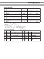
(5) Printer status signals
Error status
RINF1
RINF2
RINF3
1.
Paper out
Low
High
Low
2.
Paper near end
High
High
Low
3.
Head up
High
Low
Low
4.
Head temperature abnormality
High
Low
High
5.
Head voltage abnormality
Low
High
High
6.
Hardware abnormality
High
High
High
7.
Mark detection abnormality
Low
Low
Low
8.
Normal
Low
Low
High
NO
2. RS-232C
TF
OR
DE
N
SI
E
GN W
(1) Connector (CN2)
Connector part number
: B6B-XH-A (J.S.T.) or equivalent
Mating connector part number : XHP-6 (J.S.T.) or equivalent
(2) Connector pin assignment
No.
Signal
1
FG
3
TD
5
GND
7
SLCTIN
9
ATF
I/O
Contents No.
No.
Signal
I/O
Contents No.
-
Frame ground
2
RD
I
Receive data
O
Transmission data
4
DT R
O
Data terminal ready
-
Signal ground
6
DSR
I
Data set ready
I
Printer select
8
INPRM
I
Reset
I
Paper feed request
10
PWD
I
Power down cancellation
signal
Notes:
• Symbol “——” means a negative logic signal.
• “I” or “O” means a signal direction from the interface board side.
Cutter (CN11)
8
FTP-627MCL Series
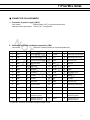
■ CONNECTOR PIN ASSIGNMENT
1. Connector for power supply (CN10)
Part number
: B6B-VH White (J.S.T) or equivalent (board side)
Mating connector part number: VHR-6 (J.S.T.) or equivalent
NO
2. Connector for printer mechanism connection (CN8)
Part number
No.
TF
OR
DE
N
SI
E
GN W
Signal
1
PHK
3
PHE
5
VH
7
GND
9
LAT
11
STB6
13
STB4
15
STB3
17
STB1
19
TH
21
GND
23
: 52030-3010 (made by Molex) or equivalent (board side)
I/O
Contents
No.
Signal
I/O
Contents
—
Photo interrupter (cathode)
2
VSEN
O
Power supply for paper senor
I
Photo interrupter (emitter)
4
VH
O
Head driving power supply
O
Head driving power supply
6
GNC
—
Ground for head
—
Ground for head
8
DIN
O
Data input
O
Data latch
10
CLK
O
Clock
O
Enable 6
12
STB5
O
Enable 5
O
Enable 4
14
VDD
O
Logic Power supply
O
Enable 3
16
STB 2
O
Enable 2
O
Enable 1
18
TH
I
Thermistor
I
Thermistor
20
GND
—
Ground for head
—
Ground for head
22
VH
O
Head driving power supply
VH
O
Head driving power supply
24
N.C.
—
Open terminal
25
SW1
O
Head open switch*
26
SW2
I
Head open switch*
27
MT/B
O
Stepping motor coil
excitation signal B
28
MT/B
O
Stepping motor coil
excitation signal B
29
MT/A
O
Stepping motor coil
excitation signal A
30
MT/A
O
Stepping motor coil
excitation signal A
* on MCL003 / MCL004/ MCL303#01 and MCL303#02 models
9
FTP-627MCL Series
■ OPTIONS
Name
Interface Cable
(between board and
equipment)
Part Number
Length (mm)
For Centronics (CN1) FTP-622Y201
500
For RS232C (CN2)
FTP-622Y301
300
Power supply cable (CN10)
FTP-622Y401
300
Near end paper sensor (CN5) if required
FTP-
NO
TF
OR
DE
N
SI
E
GN W
10
FTP-627MCL Series
■ COMMANDS
Command
Contents
HT
Moves print position to the next tab.
LF
Line feed.
FF
Feeds forms (new page).
ECS RS
Sets reverse printing.
ESC US
Resets reverse printing.
ESC ! + n
Sets print mode.
NO
ESC %+n
Download character set specification//cancellation.
ESC &+y+c1+c2+x+d1~dN
Download character definition.
ESC *+m+n1+n2+d1~dN
Sets bit image mode.
ESC ?+n
External registration character deletion.
ESC 2
ESC 3+n
ESC @
ESC A+n
ESC C+n
TF
OR
DE
N
SI
E
GN W
Sets 1/6 inch line feed length.
Sets the line feed length.
Printer initialization.
Sets the space between the line.
Sets the page length by character line.
ESC D+d1~dN+NUL
Sets the tab position.
ESC J+n
Feeds paper in forward direction and prints.
ESC K+n
ESC R+n
ESC c+1+n
ESC d+n
Reverse paper feed.
Selects international character.
Sets internal processing (including auto paper loading).
Printing and n-line feeding.
ESC e+n
Prints and reverse feeds n-lines.
ECS s+n
Sets printing speed.
ECS t+n
Character code table selection.
ESC {+n
Sets/resets upside down printing.
FS !+n
Kanji printing mode collective specification.
FS &
Kanji printing mode specification.
FS .
Kanji printing mode cancellation.
FS 9+n
Sets the detection functions.
11
FTP-627MCL Series
Commands continued
Command
Contents
FS C+n
Kanji code system selection.
FS W+n
Kanji double height and width mode specification/cancellation.
GS <
Line feeds to the next mark.
GS A+m+n
Sets the line feed length after mark detection.
GS E+n
Sets print quality.
GS V+n+m
Paper cutting.
GS e+n+m
Sets bar code width.
GS h+n
Sets bar code height.
NO
GS k+m+n+d1~dN
GS w+n
TF
OR
DE
N
SI
E
GN W
Selects bar code type and prints.
Sets bar code width magnification.
FS *+m+n1+n2+d1~dN
High speed collective image printing specified.
GS &+m+x+y1+y2+d1~dN
Registration of image data.
GS '+m+n
Prints registered image data.
FS E+n
ESC V+n
GS a+n
FS r+n
ESC EM+n
ESC X+n+m
ESC DEL+n
Fujitsu Components
International
Headquarter
Offices
Correction of impressed energy.
Right Rotation 90° specification / cancellation.
Sets and cancels status transmission. (Serial Mode)
Parameter transmission. (Serial Mode)
Setting the amount of the feeding at automatic paper load.
Setting the turning time of the motor excitation.
Deletes recorded contents in flash memory.
Japan
Fujitsu Component Limited
Gotanda-Chuo Building
3-5, Higashigotanda 2-chome, Shinagawa-ku
Tokyo 141, Japan
Tel: (81-3) 5449-7010
Fax: (81-3) 5449-2626
Email: [email protected]
Web: www.fcl.fujitsu.com
Europe
Fujitsu Components Europe B.V.
Diamantlaan 25
2132 WV Hoofddorp
Netherlands
Tel: (31-23) 5560910
Fax: (31-23) 5560950
Email: [email protected]
Web: www.fceu.fujitsu.com
North and South America
Fujitsu Components America, Inc.
250 E. Caribbean Drive
Sunnyvale, CA 94089 U.S.A.
Tel: (1-408) 745-4900
Fax: (1-408) 745-4970
Email: [email protected]
Web: www.fcai.fujitsu.com
Asia Pacific
Fujitsu Components Asia Ltd.
102E Pasir Panjang Road
#04-01 Citilink Warehouse Complex
Singapore 118529
Tel: (65) 6375-8560
Fax: (65) 6273-3021
Email: [email protected]
www.fcal.fujitsu.com
© 2003 Fujitsu Components America, Inc. All company and product names are trademarks or registered
trademarks of their respective owners. Rev. 04/03/2003
12