1
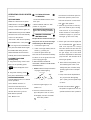
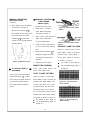
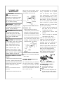
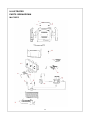
INFRARED VE N T-F RE E
PROPANE/LP GA S
SPACE H E AT E R
OWNERS OPERATION AND INSTALLATION MANUAL
WARNING : If the information in
this manual is not followed exactly,
a f i r e o r e x p l o si o n ma y r e s u l t
causing property damage, personal
injury, or loss of life.
Do not store, or use gasoline or other flammable
vapors and liquids in the vicinity of this or any
other appliance.
WHAT TO DO IF YOU SMELL GAS
ML170EPC ML170EHPC
ML250EPC ML250EHPC
WARNING : Improper installation,
a dj u st men t , a lt e ra t ion , se rvice o r
maintenance can cause injury or property damage. Refer to this manual for
correct installation and operational
procedures. For assistance or additional information consult a qualified
installer, service agency, or gas
supplier.
WARNING : This is an unvented
gas-fired heater. It uses air (oxygen)
fro m th e r oo m in wh ic h it is
installed. Provisions for adequate
combustion and ventilation air must
b e p r o v i d e d . R e f e r t o Ai r F o r
Combustion and Ventilation section on
page 5 of this manual.
Continental Appliance Inc./US Office
5 Musick
4600 Highlands Parkway S.E.
Irvine
Suite# D/E
CA 92618
Smyrna GA 30080
Nanjing PRO-COM Electric Appliance Co.,Ltd.
#6 Chuangye Road,High New Tech.Zone,
l Do not try to light any appliance.
l Do not touch any electrical switch; do not
use any phone in your building.
l Immediately call your gas supplier from a
neighbor’s phone. Follow the gas supplier’s
instructions.
l If you cannot reach your gas supplier, call
the fire department.
Installation and service must be performed by a
qu ali fie d ins tal ler, se rvi ce ag enc y o r g as
supplier.
This appliance may be installed in an
aftermarket* permanently located,
manufactured (mobile) home, where
not prohibited by local codes.
This appliance is only for use with the
type of gas indicated on the rating
plate. This appliance is not convertible
for use with other gases.
WATER VAPOR: A BY-PRODUCT OF UNVENTED ROOM
HEATERS
Water vapor is a by-product of gas combustion.An
unvented room heater produces approximately one (1)
ounce (30ml) of water for every 1,000 BTU’s
(.3KW’s) of gas input per hour. Refer to page 4.
*Aftermarket: Completion of sale, not for purpose of
resale, from the manufacturer.
Great Bridge Road North,Nanjing,210061,China.
Installer: Please leave these instructions with the
consumer.
Consumer: Please retain these instructions for
future use.
TOLL FREE NUMBER: 1-877-886-5989
PR-MCL051-05-0506
Table of Contents
Safety Information......................................................................................2
.
.
Product Features..................................................................................... 3
.
.
Local Codes..............................................................................................3
.
.
Unpacking................................................................................................. 4
Air for Combustion and Ventilation......................................................... 5
.
.
Installation.................................................................................................. 7
.
.
Connecting to Gas Supply....................................................................... 9
Checking Gas Connections...................................................................10
Operating Your Heater.............................................................................11
Cleaning & Maintenance.........................................................................14
.
.
.
Replacement Parts..................................................................................16
Specifications....................................................................................... ...16
Troubleshooting........................................................................................17
Parts List...........................................................................................................20
SAFETY INFORMATION
Make certain you read and understand all warnings. Keep this
manual for reference. It is your
guide to safe and proper operation
of this heater.
I M P O R TA N T : R e a d t h i s
ow ne r’ s ma nu al c ar ef ull y a nd
completely
b ef o r e t r y i n g
to
assemble, op erate, or servi ce
t h i s h e a t e r . Im p r o p e r u s e o f
this heater can cause serious
i n j u ry o r d e at h f r o m b u r n s ,
fire,
explosion,
electrical
s h oc k , a n d c a r bo n m o n o xi d e
poisoning.
DO NOT INSTALL HEATER UNTIL ALL
CARBON MONOXIDE POISON-
NECESSARY PROVISIONS ARE
ING MAY LEAD TO DEATH!
MADE FOR COMBUSTION AND VEN-
Early signs of carbon monoxide poi-
TILATION AIR . CONSULT THE WRIT-
s o n in g r es em b le t h e f l u w it h
TEN INSTRUCTIONS PROVIDED
headache, dizziness and/or nausea.
W ITH
FOR
If you have these signs, heater may
INFORMTION CONCERNING COM-
not be working properly. Get fresh air
BUSTION AND VENTILATION AIR. IN
at once! Have heater serviced.Some
THE ABSENCE OF INSTRUCTIONS.
people - pregnant women, persons
REFER TO THE NATIONAL FUEL
with heart or lung disease, anemia,
T H E H E AT E R
GAS CODE. ANSI Z223. 1. SECTION
those under the influence of alcohol,
5.3 OR APPLICABLE LOCAL CODES.
those at high altitude - are more af-
This heater is equipped with a PILOT
fected by carbon monoxide than
DANGER: Carbon monoxide LIGHT SAFETY SYSTEM designed to others.
poisoning may lead to death!
WARNING
When used without fresh air, heater
may give off CARBON MONOXIDE, an
odorless, poisonous gas.
turn off the heater if not enough fresh air
is available
DO NOT TAMPER WITH PILOT LIGHT
SAFETY SYSTEM!
If heater shuts off, do not relight until
you provide fresh air.
If heater keeps shutting off have it serviced . Keep burner and control compartment clean.
2
WARNING
Propane/LP Gas: Propane/LP
gas is odorless. An odor-making
agent
is added to Propane/LP
gas. The odor helps you detect a
Propane/LP gas leak . However,
the odor added to Propane/LP gas
can fade. Propane/LP gas may
be present even though no odor
exists.
SAFETY INFORMATION
WARNING:
Do not use any
accessory not appr oved for
use with this heater.
WARNING:
this heater or
be dangerous.
Any change to
its controls can
WARNING
Modles ML170HPC, ML170EHPC,
ML250EPC, ML250EHPC are equipped
for propane gas. Field conversion is
not permitted.
Due to high temperatures, heater
should be kept out of
traffic and away from furniture
and draperies.
Front surface of heater becomes
very hot when running heater.
Keep children and adults away
from hot surface to avoid burns
or clothing ignition. Heater will
remain hot for a time after shut
down. Allow surface to cool
before touching.
Do not place clothing or other
flammable material on or near
the appliance. Never place any
objects on the heater.
C areful ly su p ervi se yo un g
children when they are in the
same room with heater.
Make sure grill guard is in
place before running the heater.
Keep the
and free
materials,
flammable
appliance area clear
from combustible
gasoline, and other
vapors and liquids.
Immediately call your gas
11. Turn off and unplug heater and
supplier from a neighbor’s
let cool before servicing. Only a
phone. Follow the gas
qualified service person should
supplier’s instructions.
service and repair heater.
If you cannot reach your gas 12. Operating heater above eleva tions
of 4,500 feet could cause pilot
supplier, call the fire
outage.
department.
4. This heater shall not be installed 13. To prevent performance problems,
do not use propane/LP fuel tank of
in a bedroom or bathroom.
5. This heater needs fresh, outside
air ventilation to run properly. This
heater has an Oxygen Depletion
S en so r (O D S ) saf et y sh u t o f f
system.The ODS shuts down the
heater if not enough fresh air is
available. See Fresh Air for Combustion and Ventilation pages 5
and 7.
6. Keep all air openings in front and
bottom of heater clear and free of
debris. This will insure enough air
for proper combustion.
7. If heater shuts off. Do not relight
until you provide fresh, outside
air. If heater keeps shutting off,
have it serviced.
8. Do not operate
W here flammable liquids or
vapors are used or stored
Under dusty conditions
9. Before using furniture polish, wax,
carpet cleaner, or similar
products, turn heater off. If
heated, the vapors from these
products may create a white
powder residue within burner
less than 100lbs. capacity.
PRODUCT FEATURES
(See Figure 1, page 4)
SAFETY PILOT
This heater has a pilot with an
Oxygen Depletion Sensor(ODS)
safety shutoff system. The ODS/
pilot shuts off the heater if there
is not enough fresh air.
AUTOMATIC IGNITION
SYSTEM
This heater is equipped with an
automatic control system.
This system requires no matches,
or batteries to light heater.
TOUCH PAD
THERMOSTATIC HEAT
CONTROL
This heater was a control module
with a thermostat sensing bulb. Set
desired temperature with touch pad.
This results in the greatest heater
comfort and may result in lower
gas bills.
MANUAL OVERRIDE
CONTROL SYSTEM
(ML170EHPC, ML250EHPC)
There are two control systems,
electric and manual overide.
If no electric power is available,
rating plate. This appliance is not 10.Do not use heater if any part
you can operate heater by manual
convertible for use with other gases.
has been under water. Immediately
overide.
1. This appliance is only for use with
the type of gas indicated on the
box or on adjacent walls or
furniture.
2. Do not place propane/LP supply tank
call a qualified service technician
(s) inside any structure. Locate pro-
to inspect the room heater and to
LOCAL CODES
pane/LP supply tank(s) outside.
replace any part of the control
This heater is designed for vent-free
operation. Some state and local
codes prohibit the use of vent-free
heater.
3. If you smell gas
Shut off gas supply.
Do not try to light any appliance.
system and any gas control which
has been under water.
Do not touch any electrical switch,
do not use any phone in your
building.
3
PRODUCT FEATURES
ON/OFF Switch
Touch Pad
Cabinet Top
Burners
Grill Guard
Ignitor for Manual Override Control
System
Lower Front Panel
Door
Safety Pilot
Control Knob for Manual Override
Control System
Figure1-Vent-Free Heater
State of Massachusetts : The installation must be
made by a licensed plumber or gas fitter in the
Commonwealth of Massachusetts.
Sellers of unvented propane or natural gas-fired
supplemental room heaters shall provide to each
purchaser a copy of 527 CMR30 upon sale of the
unit.
In the State of Massachusetts, unvented propane
and natural gas-fired space heaters shall be
prohibited in bedrooms and bathrooms.
LOCAL CODES CONTINUED
Install and use heater with care. Follow all local
codes. In the absence of local codes, use the
latest edition of National Fuel Gas code ANSI
Z223.1, also known as NFPA 54*.
*Available from :
American National Standards Institute, Inc.
1430 Broadway
New York, NY 10018
National Fire Protection Association, Inc.
1 Batterymarch Park
Quincy, MA 02269 -9101
UNPACKING
1. Remove heater from carton.
2. Remove all protective packaging applied to
heater for shipment.
3. Check heater for any shipping damage. If heater
is damaged, promptly inform dealer where you
bought heater.
WATER VAPOR: A BY-PRODUCT OF VENT-FREE ROOM HEATERS
application, including ample combustion and ventilation air.
Water vapor is a by-product of gas combustion. An ventfree room heater produces approximately one (1) ounce
(30ml) of water for every 1,000 BTU’s (.3KW ’s) of gas
input per hour.
Vent-free room heaters are intended for supplemental heat
(a room) rather than a primary heat source (an entire house).
In most supplemental heat application, the water vapor does
not create a problem. In most applications, the water vapor
enhances the low humidity atmosphere experience during
cold weather.
The following steps will help insure that water vapor does
not become a problem.
1. Be sure the heater is sized properly for the
2. If high humidity is experienced, a dehumidifier may be
used to help lower the water vapor content of the air.
3. Do not use a vent-free room heater as the primary heat
source.
IMPORTANT: Vent-free heaters add moisture to
the air. Although this is beneficial, installing heater
in rooms without enough ventilation air
may
cause mildew to form from too much moisture.
See Fresh Air for Combustion and Ventilation, pages
5 and 6.
4
AIR FOR COMBUSTION
AND VENTILATION
WARNING: This heater shall
not be installed in a confined
space or unusually tight construction unless provisions are provided for adequate combustion
and ventilation air. Read the
following instructions to insure
proper fresh air for this and other
fuel-burning appliances in your
home.
PROVIDING ADEQUATE
VENTILATION
The following are excerpts from
National Fuel Gas Code. NFPA
54/ANSI Z223.1, Section 5.3. Air for
Combustion and Ventilation. All
spaces in homes fall into one of
the three following ventilation
classifications:
1. Unusually Tight Construction
2. Unconfined Space
3. Confined Space
The information on pages 5
through 6 will help you classify
your space and provide adequate
ventilation.
Unusually Tight Construction
The air that leaks around doors and
windows may provide enough fresh
air for combustion and ventilation.
However, in buildings of unusually
tight construction, you must provide
additional fresh air.
Unusually tight construction is
defined as construction where:
a. W alls and ceilings exposed to the
outside atmosphere have a
continuous water vapor retarder with a
rating of one perm (6×10 -11 kg per
pa-sec-m2) or less with openings
gasketed or sealed and
b. W eather stripping has been
added on openable windows and
doors and
c. Caulking or sealants are applied
to areas such as joints around
window and door frames, between
sole plates and floors, between
wall-ceiling joints, between wall
panels, at penetrations for plumbing,
electrical, and gas lines, and at
other openings. If your home meets
all of the three criteria above, you
must provide additional fresh air.
See Ventilation Air From
Outdoors, page 6.
If your home does not meet all of the
three criteria above, see Determining Fresh-Air Flow for Heater
Location, page 5.
Confined and
Unconfined Space
The National Fuel Gas Code
ANSI Z223.1 defines a confined
space as a space whose volume
is less than 50 cubic feet per 1,
000 Btu per hour (4.8 m3 per kw) of
the aggregate input rating of all
appliances installed in that space
and an unconfined space as a
space whose volume is not less
than 50 cubic feet per 1,000 Btu
per hour (4.8 m3 per kw) of the
aggregate input rating of all
appliances installed in that space.
Rooms communicating directly with
the space in which the appliances
are installed*, through openings not
furnished with doors, are considered a part of the unconfined
space.
This heater shall not be installed in
a confined space or unusually tight
construction unless provisions are
provided for adequate combustion
and ventilation air.
* Adjoining rooms are communicating only if there are doorless passageways or ventilation grills between them.
DETERMINING FRESH-AIR FLOW FOR HEATER LOCATION
Determining if you have a Confined or Unconfined Space*
Use this worksheet to determine if you have a confined or unconfined space.
Space: Includes the room in which you will install heater plus any adjoining rooms with doorless passageways
or ventilation grills between the rooms.
1. Determine the volume of the space (length×width×height).
cu.ft. (volume of space)
Length×Width×Height=
Example: Space size20ft. (length)×16ft.( width)×8ft. (ceiling height)=2560cu. ft. (volume of space)
If additional ventilation to adjoining room is supplied with grills or openings, add the volume of these rooms
to the total volume of the space.
2. Divide the space volume by 50 cubic feet to determine the maximum Btu/Hr the space can support.
(volume of space)÷ 50 cu. ft.=(Maximum Btu/Hr the space can support)
Example: 2560 cu. ft. (volume of space)÷50 cu.ft.=51.2 or 51.200(maximum Btu/Hr the space can support)
5
3. Add the Btu/Hr of all fuel burning appliances in the space.
Btu/Hr
Vent-free heater
Gas water heater*
Btu/Hr
Example:
Gas furnace
Btu/Hr
Gas water heater
40,000
Btu/Hr
Vented gas heater
Btu/Hr
Vent free heater +
18,000
Btu/Hr
Gas Fireplace logs
Btu/Hr
Total
= 58,000
Btu/Hr
Other gas appliances* +
Btu/Hr
Total
=
Btu/Hr
*Do not include direct-vent gas appliances. Direct-vent draws combustion air from the outdoors and
vents to the outdoors.
4. Compare the maximum Btu/Hr the space can support with the actual amount of Btu/Hr used.
Btu/Hr (maximum the space can support)
Btu/Hr (actual amount of Btu/Hr used)
Example : 51,200 Btu/Hr(maximum the space can support)
58,000 Btu/Hr(actual amount of Btu/Hr used)
The space in the above example is a confined space because the actual Btu/Hr used is more than the
maximum Btu/Hr the space can support.
You must provide additional fresh air. Your options are as follows:
A. Rework worksheet, adding the space of an adjoining room. If the extra space provides an unconfined
space, remove door to adjoining room or add ventilation grills between rooms. See Ventilation Air From
inside Building
B. Vent room directly to the outdoors. See Ventilation Air From Outdoors
C. Install a lower Btu/Hr heater, if lower Btu/Hr size makes room unconfined.
If the actual Btu/Hr used is less than the maximum Btu/Hr the space can support, the space is an
unconfined space. You will need no additional fresh air ventilation.
WARNING: If the area in which the heater may be operated is smaller than that defined as an unconfined space
or if the building is of unusually tight construction, provide adequate combustion and ventilation air by one of the
methods described in the National Fuel Gas Code, ANSI Z223.1/NFPA 54, Air for Combustion and Ventilation, or
applicable local codes.
Ventilation Air From Inside Building
This fresh air would come from an adjoining unconfined space. W hen ventilating to
an adjoining unconfined space, you must
provide two permanent openings: one within
12" of the ceiling and one within 12" of the
floor on the wall connecting the two spaces
(see options 1 and 2, Figure 2). You can also
remove door into adjoining room (see option
3, Figure 2). Follow the National Fuel Gas
Code NFPA 54/ANSI Z223.1. Section 5.3, Air
for Combustion and Ventilation for required
size of ventilation grills or ducts.
Figure 2 -Ventilation Air from Inside Building
Ventilation Air From Outdoors
Provide extra fresh air by using ventilation
grills or ducts: You must provide two
permanent openings: one within 12 " of the
ceiling and one within 12" of the floor.
Connect these items directly to the
outdoors or spaces open to the outdoors.
These spaces include attics and crawl
spaces. Follow the National Fuel Gas
Code NFPA 54/ANSI Z223.1, Section 5.3. Air
for Combustion and Ventilation for required size of ventilation grills or ducts.
IMPORTANT: Do not provide openings for
inlet or outlet air into attic if attic has a
thermostat-controlled power vent.
Heated air entering the attic will activate
the power vent.
Figure 3 -Ventilation Air from Outdoors
Rework worksheet, adding the space of the adjoining
unconfined space. The combined spaces must have
enough fresh air to supply all appliances in both spaces.
6
INSTALLATION
NOTICE: This heater is intended for use as supplemental heat.
Use this heater along with your primary heating system. Do not install
this heater as your primary heat
source. If you have a central heating system, you may run system’s
circulating b lo wer wh ile usin g
heater. This will help circulate the
heat throughout the house. In the
event of a power outage, you can
use this heater as your primary
heat source.
WARNING: A qualified
service person must install
heater. Follow all local codes.
WARNING: Electrical Grounding Instructions
This appliance is equipped with a
three-prong (grounding) plug for
your protection against shock
hazard and should be plugged
directly into a properly grounded
three-prong receptacle
WARNING: Never install
the
l
l
l
l
l
l
heater
in a bedroom or bathroom.
in a recreational vehicle.
where curtains, furniture,
clothing, or other flammable
objects are less than 36
inches from the front, top, or
sides of the heater.
as a fireplace insert.
in high traffic areas.
in windy or drafty areas.
CAUTION: If you install the
heater in a home garage
l heater pilot and burner must
be at least 18 inches above
floor.
l locate heater where moving
vehicle will not hit it.
CAUTION: This heater creates
warm air currents. These currents
move heat to wall surfaces next to
heater. Installing heater next to
vinyl or cloth wall coverings or
operating heater where impurities
(such as tobacco smoke, aromatic
candles, cleaning fluids, oil or
kerosene lamps, etc.) in the air
exist may discolor walls.
CHECK GAS TYPE
Use only Propane/LP gas. If your
gas supply is not Propane/LP, do not
install heater. Call dealer where you
bought heater for proper type heater.
LOCATING HEATER
This heater is designed for
mounting on a wall, set on floor,
away from a wall.
Purchase optional floor mounting
stand from your dealer. See
Accessories, page 16.
For convenience and efficiency,
install heater
l where there is easy access for
operation, inspection, and service
l in coldest part of room
WARNING: Maintain the
minimum clearances shown
in Figures 4, 6. If you can,
provide greater clearances
from floor, ceiling, and joining
wall.
7
Figure 4 -Mounting Clearances As
Viewed From Front Of Heater
FASTENING HEATER TO WALL
Mounting Bracket
The mounting bracket is located
on back panel of heater (see
Figure 5). It has been taped there
fo r sh ip ping . Remo ve m ou nt in g
bracket from back panel.
Figure 5 -Mounting Bracket
Location
INSTALLATION
3.
Attaching to Wall Stud: This
method provides the strongest
hold. Insert mounting screws
through mounting bracket and
into wall studs.
Attaching to Wall Anchor: This
m et ho d allow s you to att ac h
mounting bracket to hollow walls
(wall areas between studs) or to
solid walls (concrete or masonry).
Decide which method better
suits your needs. Either method
will provide a secure hold for the
mounting bracket.
Marking Screw Locations
1. Tape mounting bracket to wall
where heater will be located. Make
sure mounting bracket is level.
WARNING: Maintain
minimum clearances shown in
Figure 6. If you can, provide
greater clearances from floor
and joining wall.
2. Mark sc rew loc at io ns on
wall. (see Figure 6)
Note: Only mark last hole on
each end of mounting bracket.
Insert mounting screws through
these holes only.
3. Remove tape and mounting
bracket from wall.
Only Insert Mounting
Screws Through
Last Hole On Each
End
Floor
Model ML170EPC ML170EHPC
Adjoining Wall
Note: W all anchors, mounting
screws are
in hardware
package. The hardware package
is provided with heater.
Adjoining Wall
continued
Methods For Attaching Mounting
Bracket To Wall
Only use last hole on each end
of mounting bracket to attach
bracket to wall. These two holes
are 16 inches apart from their
cen ters.
Attach
mo u n t in g
bracket to wall only in one of two
ways:
1. Attaching to wall stud
2. Attaching to wall anchor
Only Insert Mounting
Screws Through
Last Hole On Each
4.
Insert wall anchor (wings
first) into hole. Tap anchor
flush to wall.
For thin walls (1/2" or less),
insert red key into wall
anchor. Push red key to
"pop" open anchor wings
(see Figure 8).
IMPORTANT: Do not hammer
key! For thick walls (over 1/2"
thick) or solid walls, do not pop
open wings.
End
Floor
Model ML250EPC
ML250EHPC
Figure 6 - Mounting Bracket
Clearances
Attaching to Wall Stud Method
For attaching mounting bracket to
wall studs
1. Drill holes at marked locations
using 9/64" drill bit.
2. Place mounting bracket onto
wall. Line up last hole on each
end of bracket with holes drilled
in wall.
3. Insert mounting screws through
bracket and into wall studs.
4. Tighten screws until mounting
bracket is firmly fastened to
wall studs.
Attaching to Wall Anchor Method
For attaching mounting bracket to
hollow walls (wall areas between
studs) or solid walls (concrete or
masonry)
1. Drill holes at marked locations
using 5/16" drill bit. For solid
walls (concrete or masonry), drill
at least 1" deep.
2. Fold wall anchor as shown in
Figure 7 below.
Figure 7- Folding Anchor
8
Figure 8 - Popping Open Anchor
Wing For Thin Walls
5. Place mounting bracket onto
wall. Line up last hole on
each end of bracket with wall
anchors.
6. Insert mounting screws through
bracket and into wall anchors.
7. Tighten screws until mounting
bracket is firmly fastened to wall.
Placing Heater on Mounting
Bracket
1. Locate two horizontal slots on
back panel of heater (see
Figure 9).
2. Place heater onto mounting
bracket. Slide horizontal slots
onto stand-out
tabs
on
mounting bracket.
Figure 9 - Mounting Heater Onto
Mounting Bracket
INSTALLATION
continued
Installing Bottom Bracket
(See Figure 10)
1. Install bottom bracket to heater
bottom with two screws. It may
be more convienent to remove
heater from wall mounting
bracket to attach bottom bracket
2. Place heater on mounting
bracket
3. Locate two bottom mounting
holes on wall. These holes are
near bottom on heater (see
Figure 10).
CONNECTING TO GAS
SUPPLY
WARNING: A qualified
service person mu st co nn ec t
heater to gas supply. Follow all
local codes.
WARNING: This appliance
requires a 3/8 " NPT (National
Pipe Thread) inlet connection
to the pressure regulator.
WARNING:Do not
over
tighten gas connections.
CAUTION: Never connect
heater directly to the propane/
LP supply. This heater requires
an external regulator (not
supplied). Install the external
regulator between the heater
and propane/LP supply.
Figure 10 - Installing Bottom Bracket
4. Mark screw locations on wall.
5. Remove heater from mounting
bracket.
6. If installing bottom mounting
screws into hollow or solid wall,
install wall anchors. Follow
steps 1 through 4 under Attach
ing To Wall Anchor Method. If
installing bottom mounting
screw into wall stud, drill holes
at marked locations using 9/64 "
drill bit.
7. Replace heater onto mounting
bracket.
8. Tighten both screws until heater
is firmly secured to wall. Do not
over tighten.
CAUTION: Use only new,
black iron or steel pipe. Internally-tinned copper tubing may
be used in certain areas.
Check your local codes. Use
pipe of large enough diameter
to allow proper gas volume to
heater. If pipe is too small,
CAUTION: Use pipe joint
sealant that is resistant to
liquid petroleum (LP) gas.
CAUTION: Avoid damage
to regulator. Hold gas regulator
with wrench when connecting to
gas piping and/or fittings.
INSTALLATION NEEDS
Before installing heater, make sure
you have the items listed below.
l piping (check local codes)
l sealant (resistant to Propane/
LP gas)
l equipment shutoff valve*
l ground joint union
l test gauge connection*
l sediment trap
l tee joint
l pipe wrench
9
*A CSA/AGA design-certified
equipment shutoff valve with 1/8 "
NPT tap is an acceptable alternative
to test gauge connection.
The installer must supply an
external regulator. The external
regulator will reduce incoming gas
pressure. You must reduce
incoming gas pressure to between
11 and 14 inches of water. If you
d o n o t re d u c e in c o m in g g a s
pressure, heater regulator damage
c o u l d o c c u r . In s t al l ext e rn a l
regulator with the vent pointing
d o w n as sho w n in F ig u re 11 .
Pointing the vent down protects it
from freezing rain or sleet.
Figure 11 - External Regulator with
Vent Pointing Down
Typical Inlet Pipe Diameters
All models up to 20,000 BTU’s use
3/8’’ or greater pipe;
All models 25,000 BTU’s and higher,
use 1/2” or greater pipe.
Installation must include an equipment shutoff valve, union, and
plugged 1/8" NPT tap. Locate NPT
tap within reach for test gauge hook
up. NPT tap must be upstream from
heater(see Figure 12).
Pressure Testing Gas Supply
Piping System
Test Pressures In Excess Of
1/2 PSIG (3.5 K Pa)
r
1.
2.
3.
4.
Figure 12 -Gas Connection
*A CSA/AGA design-certified equipment shutoff valve with 1/8" NPT tap
is an acceptable alternative to test gauge connection. Purchase the optional
CSA/AGA design-certified equipment shutoff valve from your dealer.
State of Massachusetts : The installation must be made by a licensed
plumber or gas fitter in the Commonwealth of Massachusetts.
Sellers of unvented propane or natural
gas-fired supplemental room heaters
shall provide to each purchaser a copy
of 527 CMR30 upon sale of the unit.
In the State of Massachusetts,unvented
propane and natural gas-fired space
heaters shall be prohibited in bedrooms and bathrooms.
IMPORTANT: Install an equipment
shut off valve in an accessible
location. The equipment shutoff
valve is for turning on or shutting
off the gas to the appliance.
Apply pipe joint sealant lightly to
male threads. This will prevent
excess sealant from going into pipe.
Excess sealant in pipe could
result in clogged heater valves.
Install sediment trap in supply line
as shown in Figure 12. Locate
sediment trap where it is within
reach for cleaning. Locate sediment trap where trapped matter is
not likely to freeze. A sediment trap
traps moisture and contaminants.
This keeps them
from going into heater controls. If
sediment trap is not installed or is
installed wrong, heater may not run
properly.
CHECKING GAS
CONNECTIONS
WARNING: Test all gas
piping and connections for leaks
after installing or servicing.
Correct all leaks at once.
WARNING: Never use an
open flame to check for a leak.
Apply a mixture of liquid soap
and water to al joints. Bubbles
forming show a leak. Correctall
leaks at once.
CAUTION: Make sure external regulator has been installed between gas supply and heater. See
guidelines under Connecting to Gas
Supply.
10
5.
6.
Disconnect appliance with its
appliance main gas valve
(control valve) and equipment
shutoff valve from gas supply
piping system. Pressures in
excess of 1/2 psig will damage
heater regulator.
Cap off open end of gas pipe
where equipment shutoff valve
was connected.
Pressurize supply piping
system by either using com
pressed air or opening
propane/LP supply tank valve.
Check all joints of gas supply
piping system. Apply mixture of
liquid soap and water to gas
joints. Bubbles forming show
a leak.
Correct all leaks at once.
Reconnect heater and equipment
shutoff valve to gas supply. Check
reconnected fittings for leaks.
Test Pressures Equal To or
Less Than 1/2 PSIG (3.5 K Pa)
1.
Close equipment shutoff valve
(see Figure 13).
2. Pressurize supply piping system
by either using compressed air
or opening propane/LP supply
tank valve.
3. Check all joints from propane/LP
supply tank to equipment shutoff
valve (see Figure 14). Ap ply
mixture of liquid soap and water
to gas joints. Bubbles forming
show a leak.
4. Correct all leaks at once.
CHECKING GAS
CONNECTIONS
Continued
Pressure Testing Heater Gas
Connections
1. Open equipment shutoff valve
(see Figure 13).
2. Open propane/LP supply tank
valve.
3. Make sure control knob of
heater is in the OFF position.
4. Check all joints from equipment
shutoff valve to control valve
(see Figure 14 ). Apply mixture
of liquid soap and water to gas
joints. Bubbles forming show
a leak.
5. Correct all leaks at once.
6. Light heater (see Operating
Heater, pages 11 and 12). Check
the rest of the
internal joints for leaks.
7. Turn off heater (see page 12 ).
Figure 13 -Equipment Shutoff Valve
.
A This appliance is equipped with
an ignition device which auto
matically lights the pilot. Do not
try to light the pilot by hand.
B. BEFORE LIGHTING smell all
around the appliance area for
gas. Be sure to smell next to
the floor because some gas is
heavier than air and will settle
on the floor .
WHAT TO DO IF YOU SMELL GAS
lDo not try to light any appliance.
lDo not touch any electric switch;
do not use any phone in your
building.
lImmediately call your gas
s u p p lier f r o m a n eig h b o r’ s
phone. Follow the gas supplier’s
instructions.
lIf you cannot reach your gas
supplier, call the fire
department.
C. Use only your hand to push on
button. Never use tools. If the
button does not operate, don’t
try to repair it, call a qualified
service technician or gas
supplier. Force or attempted
repair may result in a fire or
explosion.
D. Do not use this appliance if any
p art h as b ee n u n d er w at er.
Immediately call a qualified
service technician to inspect
the appliance and to replace
any part of the control system
and any gas control which has
been under water.
OPERATING
INSTRUCTION
For ML170EHPC, ML 250EHPC
Figure 14 -Checking Gas
Connections
OPERATING YOUR HEATER
FOR YOUR SAFETY
READ BEFORE LIGHTING
WARNING: If you do not
follow these instructions exactly, a
fire or explosion may result in
causing property damage, personal
injury or loss of life.
4. Wait five (5) minutes to clear out any
gas. Then smell for gas, including
near the floor. If you smell gas,
STOP! Follow “B” in the safety information above. If you don’t smell
gas, go to next step.
5. Plug into a properly grounded threeprong receptacle, set ON/OFF
switch on, you will hear a high pitch
sound that indicates the burner is
ready to be operated.
6. Make sure Control Knob is in ELECTRIC position.
7. Press IGN/OFF button an electric
spark will ignite the pilot.
8. Press BURNER button for desired
burner operation.
AUTO: Burner will automatically turn
on or off to desired temperature
setting, press
or
for desired
temperature setting.
MAN: Burner operates continuously.
OFF:The main burner will shut off.
9.If the appliance will not operate,
follow the instructions “To Turn Off
Gas To Appliance” and call your
service technician or gas supplier.
Note: The thermostat sensing bulb
measures the temperature of air near
the heater cabinet. This may not
always agree with room temperature
(depending on housing construction,
installation location, room size, air
temperatures, etc.) Frequent use of
your heater will let you determine
your own comfort levels.
models with manual override control
SETTING CLOCK
system heaters, make sure the
Clock setting: Press CLOCK button
Control Knob is in ELECTRIC
to select item (hour, minute). The se-
position.(See Figure 15).
1. STOP! Read the safety information
lected item will flash. Press
above before lighting.
2.Disconnect or turn off all electric
minute); Press CLOCK button again,
power to heater.
to set clock.
3. This appliance is equipped with
an ignition device which automatically lights the pilot. Do not try to light
the pilot by hand.
11
or
to change to correct time (hour,
OPERATING YOUR HEATER
continued
TO TURN OFF GAS
TO HEATER
SETTING TIMER
1.Press the IGN/OFF button on the
Auto on: With burner off, press
touch pad.
TIMER button. Then press
or
to
change to the scheduled time, then
TIMER starts timing and the TIMER
will flash. Burner will automatically
come on at the set time.
AUTO OFF: With burner operating,
press TIMER button. Then press
or
to change to the scheduled time,
then press the TIMER button again,
the TIMER starts timing and the
ELECTRIC position, press in the
control knob and turn counter clock-
2.Set the ON/OFF switch to OFF
wise
to OFF position.
4. W ait five (5) minutes to clear any
position on top panel.
NOTE: Wait one minute to light
press the TIMER button again, the
If the manual control knob points to
again after shutting off heater.
MANUAL OPERATING
INSTRUCTIONS
gas. Then smell for gas, including
near the floor. If you smell gas,
STOP! Follow “B” in the safety information on page11. If you do not
smell gas, go to the next step.
We provide the manual control system just in case of power shortage.
5. Push in gas control knob slightly and
Install battery for Manual Ignitor:
turn counterclockwise
1. Unscrew the ignitor cap.
I G N an d d e p r es s f o r f ive ( 5 )
2. Insert a AAA type battery with its
seconds. NOTE:The first time the
to PILOT/
anode (“+”) pointing out.
heater is operated after connecting
TIMER will flash. Burner will auto-
3. Screw the ignitor back cap.
the gas supply, the control knob
matically shut off at the desired time.
Note: We recommend that the battery
should be depressed for about thirty
be taken out of the ignitor when the
(30) seconds. This will allow air to
(child proof)
power supply gets right.
exit the gas system.
A. Key-press locking: Press LOCK
IF NO ELECTRIC POWER IS
LOCKING TOUCH-PAD
AVAILABLE, HEATER CAN BE OPER-
button on the operating panel,
a
1. STOP! Read the safety information
LCD.
B. Key-press unlocking: Press
and release ignitor button. This
ATED MANUALLY
symbol will appear on the
on page11 before lighting.
,
Ignitor Button
Press BLOWER button, for desired
minutes after burner goes off.
MAN: Blower operates
OFF: Blower is off.
lights.
ten (10) seconds after lighting
pilot. If pilot goes out,repeat steps
burner operation.
comes on and will go off several
pressing ignitor button until pilot
7. Keep control knob depressed for
OPERATING BLOWER
several minutes after burner
will light the pilot. If needed, keep
Control Knob
then press LOCK button to unlock.
AUTO: Blower will come on
6. With control knob pressed, push
5,6 and 7.
2. Check that gas supply to the
heater is on.
3. Remove round access door of
right side panel. Push in control
knob slightly and turn clockwise
to the OFF position.
12
8. Rotate counterclockwise
to
ON position to light burner. Do not
operate between locked positions.
MANUAL OPERATING
INSTRUCTIONS
MANUAL LIGHTING
PROCEDURE
(Match Light)
continued
9. When electric power is available
and electronic operation is
desired, turn clockwise
1. Remove lower front panel.
to
under Manual Operating
OFF position for one minute. Then
press down knob and rotate
clockwise
Figure 16 - Correct Pilot Flame
Pattern
2. Follow steps 1 through 5
Instructions on page 12.
3.
to ELECTRIC
strike match. Hold match
position. Do not operate between
locked positions.
to pilot until pilot lights.
4.
5.
Figure 15- Manual Control
W ith control knob pressed in,
4.
Keep control knob pressed in
Figure 17- Incorrect Pilot Flame
Pattern
for 30 seconds after lighting
BURNER FLAME PATTERN
pilot.
Figure 17 shows a correct burner
Rotate counterclockwise
to
ON position to light burner. Do
incorrect burner flame pattern. If
not operate between looked
burner flame pattern is incorrect,
positions.
as shown in Figure 19.
Replace lower front panel
INSPECTING BURNER
TO TURN OFF GAS TO
APPLIANCE
Check
pilot
flame pattern and
l
turn heater off (see page 11 ).
l
see Troubleshooting. pages 17
through 19.
burner flame pattern often.
Push in gas control knob slightly
PILOT FLAME PATTERN
and turn clockwise
Figure 16 shows a correct pilot
to OFF.
flame pattern. Figure 19 shows an
Do not use force. NOTE: Wait one
flame pattern. Figure 16 shows an
(1) minute with control knob in
incorrect pilot flame pattern. The
OFF position before operating
incorrect pilot flame is not touch-
heater.
ing thermocouple. This will cause
Figure 18 - Correct Burner
Flame Pattern
the thermocouple to cool. When
the thermocouple cools, the healer
will shut down. If pilot flame pattern
is incorrect, as shown in Figure 17.
l
turn heater off (see page 11)
l
see Troubleshooting, pages 17
through 19.
13
Figure 19 - Incorrect Burner
Flame Pattern
CLEANING AND
MAINTENANCE
WARNING: Disconnect
take out the control module. W hen
To clean these parts we recommend
installing , reverse the steps above.
using
compressed air no greater
(See Figures 20, 23 and 24)
than
30 PSl. Your local computer
store, hardware store, or home center
power before attempting any
may carry compressed air in a can.
maintenance or cleaning to reduce
You can use a vacuum cleaner in the
the risk of fire , electric shock or
blow position. If using compressed
personal injury. Turn off heater and
air in a can, please follow the direc-
let cool before cleaning.
tions on the can. If you don’t follow
WARNING: Failure to keep
directions on the can, you could dam-
the primary air opening(s) of the
burner(s) clean may result in soot
causing property damage.
Figure 20 Control Model Access
disconnection when servicing
panel out to remove. Disconnect
controls.W iring errors can cause
Verify proper operation after
servicing.
CAUTION: You must keep
control areas, burner, and circulat-
two wires of temperature sensor.
2.
Mark or tag each wire removed for
its exact reconnection. Remove the
four screws from the fan, when
installing , reverse the steps above.
(See Figures 21, 23 and 24)
ing air passageways of heater
3.
Blow air through the ports/slots
and holes in the burner.
Clean the pilot assembly also. A
yellow tip on the pilot flame indicates dust and dirt in the pilot
assembly. There is a small pilot air
With the unit off, lightly blow air
qualified service person. Heater
DISCONNECT WIRING OR CONTROL
Inspect burner, pilot for dust
and dirt.
the pilot assembly (see Figure 22).
heater Inspected yearly by a
bedding material, pet hair, etc.
2.
where the pilot flame comes out of
heater before each use. Have
due to excessive lint from carpeting,
at least thirty minutes.
inlet hole about two inches from
clean. Inspect these areas of
may need more frequent cleaning
Shut off the unit, including the
pilot. Allow the unit to cool for
Remove screws from the fan
bracket panel, pull the fan bracket
CAUTION:Label all wires prior to
improper and dangerous operation.
1.
DISCONNECT FAN
1.
age the pilot assembly.
through the air inlet hole. You may
Figure 21- Fan Access
CLEANING ODS/PILOT AND BURNER
blow through a drinking straw if
compressed air is not available.
l Use a vacuum cleaner,pressurized
air to clean.
MODULE
1. Remove two screws from the lower
front panel , pull the lower front panel
CLEANING BURNER AND PILOT
AIR INLET HOLE
forward then down take out thermostat
We recommend that you clean the
sensing bulb from the clip, then disco-
unit every 2,500 hours of operation
nnect the wires from to control
or every three months. W e also
module .
recommend that you keep the burner
Note: Do not confuse the mark on
tube and pilot assembly clean and
each wire.
free of dust and dirt.
2. Remove two screws and hex nuts,
14
Figure 22 - Pilot Inlet Air Hole
CLEANING HEATER CABINET
Air Passageways
l Use a vacuum cleaner or
pressurized air to clean.
Exterior
l Use a soft cloth dampened with
a mild soap and water mixture.
Wipe the cabinet to remove dust.
Figure 23-Touch
pad control System Diagram
(Model ML170EPC ML250EPC)
Figure 24- Double
Control Systems Diagram
(Mode l ML170EH PC ML250 EHPC)
15
REPLACEMENT PARTS
Use only original replacement parts.
This will protect your warranty
coverage for parts replaced under
warranty.
PARTS UNDER WARRANTY
Contact authorized dealer from
whom you purchased this product.
PARTS NOT UNDER
WARRANTY
FLOOR MOUNTING STAND
Contact authorized dealers of this
product. If they can’t supply original
replacement part(s), call PRO-COM’s
phone number (877)886-5989.
For locating heater on the floor,
away from a wall. Complete installation instructions provided with floor
mounting base stand.
TECHNICAL SERVICE
You may have further questions
about installation, operation, or
If they are unable to supply original troubleshooting. If so, contact
replacement part(s), call the number PRO-COM’S phone number (877)
on the front of manual. When contact- 886-5989.
ing your dealer or PRO-COM, have ACCESSORIES
ready:
Purchase these heater accessol your name
ries from your local dealer. If they
l your address
can not supply these accessories,
l model and serial numbers of
contact PRO-COM for information. You
your heater
can also write to the address
l how heater was malfunctioning
listed on the front of this manual.
l type of gas used (Propane/LP or
Natural gas)
BASE STAND MODEL: PF0920C
l purchase date
l warranty card
Usually, we will ask you to return the
defective part to the factory.
SPECIFICATIONS
BTU/Hr
Gas Type
Ignition
Volts
Watts
Manifold Pressure
Inlet Gas Pressure (inches of
water)
Maximum
Minimum
Dimensions, Inches (HxW xD)
Heater
Carton
W eight (pounds)
Heater
Shipping
ML170EPC(ML170EHPC)
17,000
Propane/LP Only
Automatic (Automatic/Electronic)
120 V
20 W
10" W.C
ML250EPC(ML250EHPC)
25,000
Propane/LP Only
Automatic (Automatic/Electronic)
120 V
27W
10" W.C.
14"
11"
14"
11"
23 5/8× 19 5/8× 9
27 1/2×22 ×10 1/8
23 5/8×27 1/16× 9
27 1/2× 29 7/16×11 1/8
33(34)
42(43)
38(39)
55(56)
Note: Dimensions listed are outer most points on the heater
(includes grill).
* For purposes of input adjustment.
16
TROUBLESHOOTING
WARNING: If you smell gas
l
l
l
l
Shut off gas supply.
l
If you cannot reach your gas supplier, call the fire department.
Do not try to light any appliance.
Do not touch any electrical switch; do not use any phone in your building.
Immediately cal l your gas supplier from a neighbor’s phone. Follow the gas
supplier’s instructions.
IMPORTANT: Operating heater where impurities in air exist may create odors.
Cleaning supplies, paint, paint remover, cigarette smoke, cements and glues, new
carpet or textiles, etc., create fumes. These fumes may mix with combustion air
and create odors.
Warning : Make sure that power
is turned off before proceeding.
OBSERVED PROBLEM
W hen ignition button is pressed,
there is no spark at ODS/pilot.
W hen IGN/OFF is pressed
WARNING: Turn off and let cool before servicing. Only a qualified service person should service and repair heater.
POSSIBLE CAUSE
1. No power to heater
2. ON/off switch not ON
3. W ire is damaged or loose
4. Pilot electrode position is not correct
5. Touch pad cable is not connected
6. System halt
Spark at ODS/pilot but no ignition.
1. Gas supply turned off or equipment
shut off valve closed
2. Air in gas lines when installed
3. Depleted gas supply
4. ODS/pilot is clogged
5. Gas inlet supply pressure not correct
6. W ire is damaged or loosen
7. Pilot electrude position is not correct
8. Gas valve or regulator is damage
ODS/pilot has flame, but continues
to spark.
1. Equipment shutoff valve is not
fully open
2. Thermocouple connection
loose at control module
3 Low gas pressure
4. Dirt or partially clogged ODS/pilot
5. Thermocouple damaged
6. Gas valve or regulator damaged
17
CAUTION: Never use a wire,
needle, or similar object to clean
ODS/pilot. This can damage
ODS/pilot unit.
REMEDY
1. Check the electric power
2.Turn ON/OFF swicth on
3.Check the wire for damage and
make sure connection is tight
4.Replace Pilot
5. Reconnect touch pad cable
6. Place the control knob of
manual override or OFF position
for at least 1 minute, then trun to
ELECTRIC position
1.Turn on gas supply or open
equipment shutoff valve
2. Press ignitor button again until
air is removed
3.Contract local gas company
4.Clean ODS/pilot (see cleaning
and Maintenance, Page 12) or
replace ODS/pilot assembly
5.Have qualified service technician
check inlet pressure
6.Check the wire for damage and
make sure connection is tight
7.Replace Pilot
8.Contact dealer or PRO-COM
1. Fully open equipment shutoff
valve
2. Check that connectors secure
on module
3. Contact local natural gas company
4.Clean ODS/pilot (see Cleaning and
Maintenance, Page 13) or replace
ODS/pilot assembly
5. Replace thermocouple
6.Contact dealer or PRO-COM
TROUBLESHOOTING
Continued
POSSIBLE CAUSE
OBSERVED PROBLEM
ODS/pilot has flame, but burner(s)
does not light
1.
Burner injector is clogged
2. Inlet gas pressure is too low
3. Thermocouple leads discon
nected or improperly connected
4. Batteries weak
Delayed ignition of burner(s)
1. Manifold pressure is too low.
2. Burner injector is clogged
Burner backfiring during combustion 1. Burner injector is clogged or
damaged
2. Burner is damaged.
3. Excessive supply pressure
damaged regulator
REMEDY
1. Clean burner injector (see Cleaning
and Maintenance, Page14) or
replace burner injector
2. Contact local Propane/LP gas company
3. Reconnect leads (See wiring
diagram)
4. Replace batteries
1. Contact local Propane/LP gas company.
2. Clean burner (see Cleaning and
Maintenance, Page 14) or replace
burner injector
1. Clean burner injector (see Cleaning
and Maintenance, Page 14) or
replace burner injector(s)
2. Replace burner
3. Replace gas regulator
1. Plaque damaged
1. Replace burner
2. Inlet gas pressure is too low
2. Contact local propane/LP gas
company
Slight smoke or odor during
initial operation
1. Residues from manufacturing
processes
1. Problem will stop after a few hours
of operation
Heater produces a clicking/ticking
noise just after burner is lit or
shut off
1. Metal expanding while heating or 1. This is common with most
contracting while cooling
heaters. If noise is excessive,
contact qualified service person
White powder residue forming
within burner box on adjacent
walls or furniture
1.
Burner Plaque(s) does not glow
Heated vapors from furniture
polish, wax, carpet cleaners,
etc. turn into white powder
residue
18
1. Turn heater off when using furniture
polish, wax, carpet cleaner, or
similar products
TROUBLESHOOTING
Continued
OBSERVED PROBLEM
Heater produces unwanted odors
Heater shuts off in use (ODS
operates)
POSSIBLE CAUSE
REMEDY
1. Heater is burning vapors from 1.
paint, hair spray, glues, etc.
(See IMPORTANT statement
at beginning of troubleshooting)
2. Gas leak. See WARNING
2.
Statement at beginning of
troubleshooting
1. Not enough fresh air is available. 1.
2. Low line pressure
2.
3. ODS/pilot is partially clogged 3.
1. Gas leak. See W ARNING
Gas odor exists even when heater is
Statement at beginning of
shut off
trouble
shooting
Gas odor during combustion
Moisture/condensation on windows
Ventilate room. Stop using odor
causing products while heater
is running
Locate and correct all leaks(see
Checking Gas Connections,
Page 10)
Open window and/or door for,
ventilation
Contact local propane/LP gas
company
Clean ODS/pilot (see Cleaning
Page 14)
1.
Locate and correct all leaks(see
Checking
Gas Connections,
Page 10)
1.
1. Foreign matter between control 2.
valve and burner
2. Gas leak See W ARNING
Statement at begining of
troubleshooting
Remove foreign matter.
Locate and correct all leaks
(see Checking Gas
Connections, Page 10)
1.
Refer to Air for Combustion and
Ventilation requirements , Page
5
1. Not enough combustion/
ventilation air
NOTE: BEFORE YOU SWITCH TO “ELECTRIC” CONTROL LEVEL FROM MANUAL CONTROL, YOU NEED TO
TURN THE KNOB TO “OFF” LEVEL FIRST AND WAIT FOR ONE MINUTE, THEN TURN THE KNOB TO “ELECTRIC”.
IN CASE OF “ELECTRONIC” CONTROL LEVEL DOES NOT WORK, PLEASE TURN THE CONTROL KNOB COUNTERCLOCKWISE TO “OFF” LEVEL AND WAIT FOR ONE MINUTE.
19
ILLUSTRATED
PARTS BREAKDOWN
ML170EPC
20
PARTS LIST
This list contains replaceable parts for your heater. W hen ordering replacement
parts, following the instructions listed under Replacement Part on page16 of this
manual.
ML170EPC
DESCRIPTION
KEY
NO.
ML170EPC
1
2
3
4
5
6
7
7-1
7-2
8
9
10
11
12
13
14
15
16
MCL001-02
MCL008-01
VL067-01
NAM02-00
MCB19004
NAY03-05-01
PART NO.
ND2808X400-R
ND0803-B
ND0807
ML090-05
MCL090-02
MCB29002
MCB09002
NRV81-10
SIT852001
NAM03-00
NFHTX100-D
MCB62001
Cabinet Top
Cabinet Top Hinge
ON/OFF Switch
Top Pad
Burner Assembly
Igniting Cable
ODS Pilot Assembly
Thermocouple
Igniting Electrode
Injector
Injector
Grill Guard Assembly
Lower Front Panel Assembly
Regulator
Control Valve
Control Module
Blower
Blower Thermostat Switch ASM
QTY
1
2
1
1
1
1
1
1
1
2
1
1
1
1
1
1
1
1
PART AVAILABLE NOT SHOWN
MCB28001
Hardware Assembly
21
1
ILLUSTRATED
PARTS BREAKDOWN
ML170EHPC
22
PARTS LIST
ML170EHPC
KEY
NO.
1
2
3
4
5
6
7
8
9
10
11
12
13
14
15
15-1
15-2
16
17
18
19
This list contains replaceable parts for your heater. W hen ordering replacement
parts, following the instructions listed under Replacement Part on page16 of this
manual.
ML170EHPC
PART NO.
DESCRIPTION
Cabinet Top
Cabinet Top Hinge
ON/OFF Switch
Touch Pad
Right Panel
Grill guard Assembly
MCB29002
Lower Front Panel Assembly
MCB09002
Control Module
NAM03-00
NRVA81FIL-10 Regulator
Ignitor
AL092-01
Control Knob Assembly
MB16004
Control Switch
MCL099-01
Control Valve
NV2020-22
Burner Assembly
MCB19004
ODS Pilot Assembly
ND1808X400-C
Thermocouple
ND0803-C2
Ignitor Electrode
ND0807
Injector
MCL090-02
Injector
ML090-05
Blower Thermostat Switch Assembly
MCB62001
NFHTX100-D Blower
MCL001-02
MCL008-01
VCL067-01
NAM02-00
MCL003-01
QTY
1
2
1
1
1
1
1
1
1
1
1
1
1
1
1
1
1
1
2
1
1
PART AVAILABLE NOT SHOWN
MCB28001
Hardware Assembly
23
1
ILLUSTRATED
PARTS BREAKDOWN
ML250EPC
24
PARTS LIST
ML250EPC
This list contains replaceable parts for your heater. W hen ordering replacement
parts, following the instructions listed under Replacement Part on page16 of this
manual.
KEY
NO.
1
2
3
4
5
6
7
8
9
9-1
9-2
10
11
12
13
14
15
ML250EPC
DESCRIPTION
PART NO.
MCL003-01B
MCL001-01
MCL008-01
MCB62001
NFHTX100-D
MCB29001
MCB09001
MCB19001
ND2808X400-R
ND0803-4C
ND0807-C2
NAM03-00
NAM03-07
NRV81FIL-10
SIT852002
ML090-02
VL067-01
Door
Cabinet Top
Cabinet Top Hinge
Blower Thermostat Switch Assembly
Blower
Grill guard Assembly
Lower Front Panel Assembly
Burner Assembly
ODS /Pilot Assembly
Thermocouple
Ignitor Electrode
Control Module Assembly
Temperature Sensor
Regulator
Valve
Injector
ON/OFF Switch
QTY
1
1
2
1
1
1
1
1
1
1
1
1
1
1
1
5
1
PART AVAILABLE NOT SHOWN
MCB28001
Hardware Assembly
25
1
ILLUSTRATED
PARTS BREAKDOWN
ML250EHPC
26
PARTS LIST
ML250EHPC
This list contains replaceable parts for your heater. W hen ordering replacement
parts, following the instructions listed under Replacement Part on page16 of this
manual.
KEY
NO.
ML250EHPC
1
2
3
4
5
6
7
8
9
9-1
9-2
10
11
12
13
14
15
16
17
18
MCL003-01B
MCL001-01
MCL008-01
MCB62001
NFHTX100-D
MCB29001
MCB09001
MCB19001
PART NO.
ND4808X400-C
ND0803-4C
ND0807-C2
NAM03-00
NAM03-07
NRV81FIL-10
AL092-01
MB16004
MCL099-01
NV2020-22
ML090-02
VL067-01
DESCRIPTION
Door
Cabinet Top
Cabinet Top Hinge
Blower Thermostat Switch Assembly
Blower
Grill guard Assembly
Lower Front Panel Assembly
Burner Assembly
ODS /Pilot Assembly
Thermocouple
Ignitor Electrode
Control Module
Temperature Sensor
Regulator
Ignitor
Control Knob ASM
Control Switch
Control Valve
Injector
ON/OFF Switch
QTY
1
1
2
1
1
1
1
1
1
1
1
1
1
1
1
1
1
1
5
1
PART AVAILABLE NOT SHOWN
MCB28001
Hardware Assembly
27
1