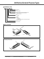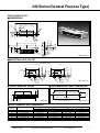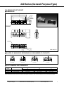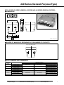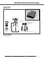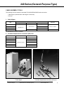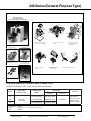
1
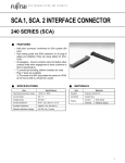
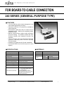
FOR BOARD-TO-CABLE CONNECTION
240 SERIES (GENERAL-PURPOSE TYPE)
■ FEATURES
• 1.27 mm (0.050 in.) pitch contact arrangement in two
rows enables high-density mounting.
• Connectors with 20 to 96 contacts are available for
various purposes.
• Discrete-wire (AWG #28, #30) I/O cables can be
assembled by IDC. Metal covers completely protect
sockets from EMI.
• Bellows contacts ensure stable contact preventing
pins from bending. The bellows contacts also have
excellent stability with repeated insertion and
extraction.
• Tails are spaced in a four-row staggered arrangement
(2.54 mm × 1.905 mm) (0.100 in. × 0.075 in.) for easy
PC board design.
• Insulation is UL-approved (94V-0) and is washable.
• An FCN-230 EMI cover and dust cap can be used
together.
■ SPECIFICATIONS
■ MATERIALS
Item
Specifications
Item
Materials
Operating temperature range
–55°C to +105°C
Insulator
Polyester (UL94V-0)
Current rating
DC 1 A
Conductor
Copper alloy
Voltage rating
AC 240 V
Contact resistance
35 mΩ max. (DC 6 V, 0.1A)
Insulation resistance
1000 MΩ min. (DC 500 V)
Dielectric withstand voltage
AC 750 V for 1 minute
Insertion force (kg)
4.5 kg max. (20 pins)
Withdrawal force (kg)
0.6 kg min. (20 pins)
Applicable PC board
1.6 mm (0.063 in.) thick
Applicable wire (standard)
IDC: AWG #28 and #30 stranded wires with
φ 0.5 to 0.88 mm (0.020 to 0.035 in.)
insulation diameter.
Soldering: AWG #26 max. (reference)
(The applicable wires depend on the number
of contacts. See the descriptions of IDC
sockets and metal covers.)
Specifications
subject to change
Dimensions are in millimeters (inches)
Plating
Contact
Gold plating
Terminal
Palladium plating
www.fcai.fujitsu.com
1
240 Series (General-Purpose Type)
■ ORDERING CODE
FCN-24 5 P 050-G / E
E: Metal type
Plating
G: Gold plating
Number of contacts: 20, 28, 36, 50, 68, 80, and 96
Soldering eyelet: 20, 28, 36, 50, and 96
Straight: 36 and 50
Body
J: Socket
P: Plug
Tail type
4: Straight
5: Right-angle
7: Insulation displacement connection (IDC) socket
240 series connector
Fujitsu connector
■ APPLICATIONS
FCN-245P × × × -G/E
FCN-247J × × × -G/E (Socket body)
FCN-230C × × × -A/E (Cover)
Docking Connectors
FCN-245P 096 -G/E
Specifications
subject to change
Dimensions are in millimeters (inches)
C630-5332-T748
www.fcai.fujitsu.com
2
240 Series (General-Purpose Type)
STRAIGHT PLUG
■ DIMENSIONS
A
B
C
2
(0 -M2
.0 .5
98
)
End terminal
7.3
(0.278)
10.5 (0.413)
1.27 (0.050)
No. 1
No. 2
No. 3
0.4
(0.015)
3.4
(0.133)
5.4
5.6
(0.220) (0.212)
D
1.27 (0.050)
0.3 (0.011)
C
1.905
(0.075)
Unit: mm (in.)
■ MOUNTING HOLE LAYOUT
(±004)
f0
.8
2(0 φ2.8
.1
10
)
1.27 ±0.1
(0.050 ±0.004)
C ±0.1
End terminal
f0
No. 1
0±
0.
06
(±004)
1.27 ±0.1
(0.050 ±0.004)
No. 1
.8
0±
0.
No. 2
No. 3
1.905 ±0.1 (0.075 ±0.004)
C ±0.1
End terminal
50 contacts
B ±0.1 (±004)
2(0 φ2.8
.1
10
)
B ±0.1 (±004)
1.905 ±0.1 (0.075 ±0.004)
(Component side)
36 and 96 contacts
06
No. 2
No. 3
Unit: mm (in.)
■ RECOMMENDED PANEL DIMENSIONS
R 1.5 ±0.1
(R 0.059±0.004)
8.3 ±0.1
(0.326 ±0.004)
(D + 0.5) ±0.1 ((D + 0.019) ±0.004)
B ±0.1 (±0.004)
Unit: mm (in.)
Recommended panel thickness t = 1
■ PART NUMBERS AND DIMENSIONS
Number of
contacts
36
50
96
Part number
FCN-244P036-G/E
FCN-244P050-G/E
FCN-244P096-G/E
Specifications
subject to change
A
43.56 (1.714)
52.45 (2.064)
81.66 (3.214)
Dimensions: mm (in.)
C
B
21.59 (0.850)
37.56 (1.478)
30.48 (1.200)
46.45 (1.828)
59.69 (2.350)
75.66 (2.978)
Dimensions are in millimeters (inches)
www.fcai.fujitsu.com
D
33.46 (1.317)
42.35 (1.607)
71.56 (2.817)
3
240 Series (General-Purpose Type)
RIGHT-ANGLE PLUG
■ DIMENSIONS
A
B
C
End terminal
1.27 (0.050)
10.5
(0.413)
7.3
(0.287)
2
(0 -M2
.0 .5
98
)
0.6 (0.023)
No. 1
1.905
(0.075)
11.8
(0.464)
6.705
(0.263)
5.9
(0.232)
0.8 (0.31)
0.3 (0.011)
No. 3
D
4 (0.157)
No. 2
3.4 (0.133)
2-M2.5
(0.098)
4.37 (0.172)
Unit: mm (in.)
8.47
(0.333)
■ MOUNTING HOLE LAYOUT
(Component side)
φ
(0 0.8
.0 0 ±
31 0.0
±0
6
No. 1
No. 2
.0
B ±0.1 (±0.004)
C ±0.1 (±0.004)
End terminal
φ
(0 0.8
.0 0 ±
31 0.0
±0
6
2(0 φ2.
.1 8
10
)
.0
02
02
)
)
No. 3
4.7 –0
(0.185 –0)
6.3 max.
(0.141 max.)
No. 2
2(0 φ2.
.1 8
10
)
No. 3
Unit: mm (in.)
(D + 0.5) ±0.1 ((D + 0.019) ±0.004)
R 1.5 ±0.1
(R 0.059±0.004)
8.3 ±0.1
(0.326 ±0.004)
3.2 –0
(0.125 –0)
5.5 –0
(0.216 –0)
3.4 –0
(0.133 –0)
No. 1
■ RECOMMENDED PANEL DIMENSIONS
■ PANEL INHIBITED AREAS
B ±0.1 (±0.004)
1.27±0.1
(0.050±0.004)
1.905 ±0.1 (0.075±0.004)
1.27±0.1
(0.050±0.004)
3.7 mm
(0.146 in.) min.
C ±0.1 (±0.004)
1.905 ±0.1 (0.075±0.004)
B ±0.1 (±0.004)
End terminal
50 contacts
3.7 mm
(0.146 in.) min.
20, 28, 36, 68, 80 and 96 contacts
B ±0.1 (±0.004)
Unit: mm
Recommended panel thickness t = 1
Unit: mm (in.)
■ PART NUMBERS AND DIMENSIONS
Number of
contacts
20
28
36
50
68
80
96
Part number
FCN-245P020-G/E
FCN-245P028-G/E
FCN-245P036-G/E
FCN-245P050-G/E
FCN-245P068-G/E
FCN-245P080-G/E
FCN-245P096-G/E
Specifications
subject to change
A
33.40 (1.314)
38.48 (1.514)
43.56 (1.714)
52.45 (2.064)
63.88 (2.514)
71.50 (2.814)
81.66 (3.214)
Dimensions: mm (in.)
C
B
11.43 (0.450)
27.40 (1.078)
16.51 (0.650)
32.48 (1.278)
21.59 (0.850)
37.56 (1.478)
30.48 (1.200)
46.45 (1.828)
41.91 (1.650)
57.88 (2.278)
49.53 (1.950)
65.50 (2.578)
59.69 (2.350)
75.66 (2.978)
Dimensions are in millimeters (inches)
www.fcai.fujitsu.com
D
23.30 (0.917)
28.38 (1.117)
33.46 (1.317)
42.35 (1.667)
53.78 (2.117)
61.40 (2.417)
71.56 (2.817)
4
240 Series (General-Purpose Type)
SOLDERING EYELET SOCKET
■ DIMENSIONS
C
No. 3
B
No. 2
A
No. 1
5.5
(0.216)
9
(0.354)
1.27 (0.050)
13.4
(0.527)
6.9
(0.271)
End terminal
End terminal
No. 1
No. 2
No. 3
Unit: mm (in.)
■ SHAPES OF MAIN BODY DEPENDING ON THE NUMBER OF CONTACTS
20 contacts
28 contacts
36 contacts
50 contacts
■ PART NUMBERS AND DIMENSIONS
Number of
contacts
20
28
36
50
Part number
FCN-241J020-G/E
FCN-241J028-G/E
FCN-241J036-G/E
FCN-241J050-G/E
A
11.43 (0.450)
16.51 (0.650)
21.59 (0.850)
30.48 (1.200)
Dimensions: mm (in.)
B
16.25 (0.639)
21.33 (0.839)
26.41 (1.039)
35.30 (1.389)
C
19.25 (0.757)
24.33 (0.957)
29.41 (1.157)
38.30 (1.507)
These accessories are also used for the FCN-230 series (general-purpose). Refer to the data sheet for the FCN-230 series for details.
Specifications
subject to change
Dimensions are in millimeters (inches)
www.fcai.fujitsu.com
5
240 Series (General-Purpose Type)
INSULATION DISPLACEMENT CONNECTION (IDC) SOCKET
■ DIMENSIONS
Body
C
No. 3
B
No. 2
A
No. 1
5.5
(0.216)
9
(0.354)
1.27 (0.050)
6.9
(0.271)
20.3 (0.799)
End terminal
Assembly drawing
D
6.9
(0.271)
1.7
(0.066)
Cover 2
1.7
(0.066)
5.4 3.6 (0.050)
(0.212)
5.4
(0.212)
D
2.2
(0.086)
3
(0.050)
8.4
(0.330)
Cover 1
3
(0.050)
8.4
(0.330)
20.3
(0.799)
5.4
(0.212)
Unit: mm (in.)
■ SHAPES OF MAIN BODY DEPENDING ON THE NUMBER OF CONTACTS
20 contacts
28 contacts
36 contacts
50 contacts
68 and 80 contacts
■ PART NUMBERS AND DIMENSIONS
Number of
contacts
20
28
36
50
68
80
96
Insulation diameter of
applicable wire
φ0.5 to 0.65 mm
φ0.65 to 0.8 mm
φ0.8 to 0.88 mm
φ0.5 to 0.65 mm
φ0.8 to 0.88 mm
φ0.5 to 0.65 mm
φ0.8 to 0.88 mm
φ0.5 to 0.65 mm
φ0.65 to 0.8 mm
φ0.8 to 0.88 mm
φ0.5 to 0.65 mm
φ0.65 to 0.8 mm
φ0.8 to 0.88 mm
φ0.5 to 0.65 mm
φ0.5 to 0.65 mm
Part number
FCN-247J020-G/E
FCN-247J020-G/G
FCN-247J020-G/F
FCN-247J028-G/E
FCN-247J028-G/F
FCN-247J036-G/E
FCN-247J036-G/F
FCN-247J050-G/E
FCN-247J050-G/G
FCN-247J050-G/F
FCN-247J068-G/E
FCN-247J068-G/G
FCN-247J068-G/F
FCN-247J080-G/E
FCN-247J096-G/E
A
Dimensions: mm (in.)
B
C
D
11.43 (0.450)
16.25 (0.639)
19.25 (0.757)
16.75 (0.659)
16.51 (0.650)
21.33 (0.839)
24.33 (0.957)
21.83 (0.859)
21.59 (0.850)
26.41 (1.039)
29.41 (1.157)
26.91 (1.059)
30.48 (1.200)
35.30 (1.339)
38.30 (1.507)
35.80 (1.409)
41.91 (1.650)
46.73 (1.839)
49.73 (1.957)
47.23 (1.859)
49.53 (1.950)
59.69 (2.350)
54.35 (2.139)
64.51 (2.539)
57.35 (2.257)
67.51 (2.657)
54.85 (2.159)
65.01 (2.559)
These accessories are also used for the FCN-230 series (general-purpose). Refer to the data sheet for the FCN-230 series for details.
Specifications
subject to change
Dimensions are in millimeters (inches)
www.fcai.fujitsu.com
6
240 Series (General-Purpose Type)
METAL COVER (230 SERIES (GENERAL-PURPOSE) AND 240 SERIES (GENERAL-PURPOSE))
■ DIMENSIONS
12.0
(0.472)
10.0
(0.393)
32.5 (1.279)
A
D
B
Unit: mm (in.)
C
■ SHAPES OF MAIN BODY DEPENDING ON THE NUMBER OF CONTACTS
20, 28, 36, 50 and 68 contacts
■ PART NUMBERS AND DIMENSIONS
Number of
contacts
20
28
36
50
68
96
Part number
FCN-230C020-A/E
FCN-230C020-C/E
FCN-230C028-A/E
FCN-230C028-C/E
FCN-230C036-A/E
FCN-230C036-C/E
FCN-230C050-A/E
FCN-230C050-C/E
FCN-230C068-A/E
FCN-230C068-C/E
FCN-230C096-C/E
Specifications
subject to change
A
Dimensions: mm (in.)
B
28.95 (1.139)
21.15 (0.832)
34.03 (1.339)
26.23 (1.032)
39.11 (1.539)
31.31 (1.232)
48.00 (1.889)
40.20 (1.582)
59.43 (2.339)
51.63 (2.032)
77.21 (3.039)
69.41 (2.732)
Dimensions are in millimeters (inches)
C×D
6.5 × 4.5 (0.255 × 0.177)
8.5 × 8.2 (0.334 × 0.322)
6.5 × 6.0 (0.255 × 0.236)
7.2 × 8.5 (0.283 × 0.334)
9.5 × 8.0 (0.374 × 0.314)
10.0 × 9.7 (0.393 × 0.381)
8.5 × 7.0 (0.334 × 0.275)
10.0 × 9.7 (0.393 × 0.381)
9.0 × 8.0 (0.354 × 0.314)
10.0 × 9.0 (0.393 × 0.354)
9.0 x 11.5 (0.381 × 0.452)
www.fcai.fujitsu.com
7
240 Series (General-Purpose Type)
METAL COVER WITH POLARIZATION [230 SERIES (GENERAL-PURPOSE) AND 240
SERIES (GENERAL-PURPOSE)]
This metal cover prevents a connector from being incorrectly inserted when two or more connectors with the same
number of contacts are mounted on a PC board. Use the metal cover together with the polarization guide.
7.5
(0.295)
■ DIMENSIONS
12.0
(0.472)
10.0
(0.393)
A
D
C
B
A
1
2
3
4
5
32.5 (1.279)
E
B
Rivet
1.4 (0.055)
C
φ1.95
(0.472)
φ3
(0.472)
D
0.4 (0.015)
Part number : C630-5296-X801
Purchase a rivet if necessary.
Unit: mm (in.)
■ SHAPES OF MAIN BODY DEPENDING ON THE NUMBER OF CONTACTS
20 contacts
28 and 36 contacts
50, 68, 80 and 96 contacts
■ PART NUMBERS AND DIMENSIONS
Number of
contacts
20
28
36
50
68
80
96
Part number
FCN-230C020-B/E
FCN-230C028-B/E
FCN-230C036-B/E
FCN-230C036-D/E
FCN-230C050-B/E
FCN-230C050-D/E
FCN-230C068-B/E
FCN-230C068-D/E
FCN-230C080-D/E
FCN-230C096-B/E
FCN-230C096-D/E
Specifications
subject to change
A
28.95 (1.139)
34.03 (1.339)
Dimensions: mm (in.)
B
21.15 (0.852)
26.23 (1.032)
39.11 (1.539)
31.31 (1.232)
48.00 (1.899)
40.20 (1.582)
59.43 (2.339)
51.63 (2.032)
67.05 (2.639)
77.21 (3.039)
77.21 (3.039)
59.25 (2.322)
59.25 (2.332)
51.00 (2.007)
Dimensions are in millimeters (inches)
C×D
6.5 × 4.5 (0.255 × 0.177)
6.5 × 6.0 (0.255 × 0.236)
9.5 × 8.0 (0.374 × 0.314)
10.0 × 9.0 (0.393 × 0.354)
8.5 × 7.0 (0.334 × 0.275)
14.7 × 10.4 (0.578 × 0.409)
9.0 × 8.0 (0.354 × 0.314)
14.7 × 10.4 (0.578 × 0.409)
9.0 × 10.0 (0.354 × 0.393)
8.0 × 10.0 (0.314 × 0.393)
9.0 × 11.5 (0.374 × 0.452)
www.fcai.fujitsu.com
8
240 Series (General-Purpose Type)
PLASTIC COVER
■ DIMENSIONS
9.5
11.4
(0.448)
Configuration
21 (0.826)
Cable cramp
Pan head machine screw
Locking lever
F
37 (1.456)
C020-02
C
Cable diameter : φ5.8 mm (0.228 in.)
Unit: mm (in.)
■ PART NUMBERS
FCN-240C020-Y/S
Specifications
subject to change
Dimensions are in millimeters (inches)
www.fcai.fujitsu.com
9
240 Series (General-Purpose Type)
CABLE ASSEMBLY TOOLS
The following tools are needed to assemble FCN-230/230R/240/240R series connectors.
• Cable aligner (semiautomatic cable aligner or hand tool)
• IDC tool
1. Cable Aligner
Semiautomatic cable aligner
Item
Hand tool
Body/Controller
Bed
Adaptor
FCN-237J
FCN-K560-A-xxx
FCN-237R
FCN-247J
FCN-P560-2/A
FCN-K560-R-xxx
FCN-M561-A/C
FCN-247R
FCN-237T-T062/H
FCN-K560-K-xxx
FCN-P560-2/J
FCN-K560-J-xxx
FCN-247T-T061/H
xxx indicates the number of contacts.
2. Insulation Displacement Connection (IDC) tool
Item
Hand press
Head/Table
FCN-237J
FCN-237T-T064/H
FCN-237R
FCN-237T-T067/H
FCN-237D
FCN-247J
FCN-237T-T075/H
FCN-237T-T109/H
FCN-247T-T066/H
FCN-247R
FCN-247T-T068/H
FCN-247D
FCN-247T-T077/H
• Cable aligner
Specifications
subject to change
Dimensions are in millimeters (inches)
• Insulation displacement connection (IDC) tool
www.fcai.fujitsu.com
10
240 Series (General-Purpose Type)
Semi-Automatic Tools
Cable Aligning Machine
Main Body (FCN-M551-120, FCN-M551-220)
Wires
Clamp lever
Cover 2
Cover 1
Applicator
Sinking comb
Applicator
Clamp section
Stand
Cable key
1. Set the applicator on the stand.
Set covers 1 and 2 in the applicator.
Head (FCN-H550-1/A)
Bed
3. Set the applicator onto the
installation table and begin
cable alignment
2. Push the wire into the sinking
combs.
Stand (FCN-D550)
Lock
Handle
Lever
Guide
Applicator (FCN-A550-1/A-xxx)
Stopper
IDC Tool (FCN-237T-T109/H,
FCN-237T-T067/H locator)
5. Put covers together and
pre-assemble them to
the connector body.
4. Take the covers off the
applicator.
6. Conduct final aaembly as shown.
FCN-240R SERIES IDC ROUND-CABLE CONNECTORS
SOCKET: FCN-247J***-G/E (***: 020, 028, 036, 050, 068 ,080, 096)
Pos No.
20
|
68
96
Applied Wire
(wire Dia.: mm)
#28 to #30
(0.5 to 0.65)
Connector Part
number
Cable Aligner
IDC Tool
Hand Tool
FCN-247J020-G/F
|
FCN-247J080-G/F
FCN-237T-T062/H
|
FCN-237T-T043/H
FCN-247J096-G/E
FCN-237T-T062/H
Semi-Auto
(See below*)
HAND PRESS:
FCN-237T-T109/H
HEAD & Locator:
FCN-247T-T066/H
Semi-automatic-Medium Level
Body:
:FCN-M551-120
Head Assembly: :FCN-H550
Applicator:
:FCN-A550-1/A-***(***: 020, 028, 036, 050, 068, 080)
Stand:
:FCN-D550
Specifications
subject to change
Dimensions are in millimeters (inches)
www.fcai.fujitsu.com
11
240 Series (General-Purpose Type)
Fujitsu Components
International
Headquarter
Offices
Japan
Fujitsu Component Limited
Gotanda-Chuo Building
3-5, Higashigotanda 2-chome, Shinagawa-ku
Tokyo 141-0022, Japan
Tel: (81-3) 5449-7010
Fax: (81-3) 5449-2626
Email: [email protected]
Web: www.fcl.fujitsu.com
Europe
Fujitsu Components Europe B.V.
Diamantlaan 25
2132 WV Hoofddorp
Netherlands
Tel: (31-23) 5560910
Fax: (31-23) 5560950
Email: [email protected]
Web: emea.fujitsu.com/components
North and South America
Fujitsu Components America, Inc.
250 E. Caribbean Drive
Sunnyvale, CA 94089 U.S.A.
Tel: (1-408) 745-4900
Fax: (1-408) 745-4970
Email: [email protected]
Web: http://us.fujitsu.com/components
Asia Pacific
Fujitsu Components Asia Ltd.
102E Pasir Panjang Road
#01-01 Citilink Warehouse Complex
Singapore 118529
Tel: (65) 6375-8560
Fax: (65) 6273-3021
Email: [email protected]
www.fcal.fujitsu.com
© 2007 Fujitsu Components America, Inc. All rights reserved. All trademarks or registered trademarks are the property of their respective owners. Fujitsu Components America, Inc. or its affiliates do not warrant that the content of the
datatasheet is error free. In a continuing effort to improve our products, Fujitsu Components America, Inc. or its
affiliates reserve the right to change specifications/datasheets witout prior notice. Rev. November 2, 2007.
Specifications
subject to change
Dimensions are in millimeters (inches)
www.fcai.fujitsu.com
12