1
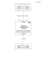
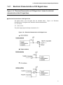
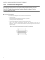
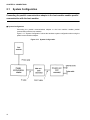
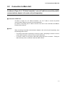
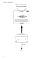
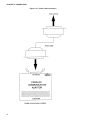
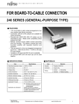
CM41-00413-2E
FUJITSU SEMICONDUCTOR
CONTROLLER MANUAL
2
F MC
FAMILY
PARALLEL COMMUNICATIONS ADAPTER
MB2142-03
HARDWARE MANUAL
2
F MC
FAMILY
PARALLEL COMMUNICATIONS ADAPTER
MB2142-03
HARDWARE MANUAL
FUJITSU LIMITED
PREFACE
■ Objectives and Intended Readers
The MB2142-03 support tool (parallel communications adapter) is designed to enable the
development and evaluation of products based on the F2MC* famiy.
The MB2142-03 is connected to the main unit (MB2141A).
This enables the main unit to perform parallel communication with the host machine (such as a
personal computer).
This manual describes the handling and connection of the MB2142-03. It is aimed at engineers
responsible for the development of products based on the F2MC, using the MB2142-03.
Refer to the following related manual as necessary:
•
Related manual
F2MC FAMILY MB2140series MAIN UNIT (MB2141A) HARDWARE MANUAL
*: F2MC stands for FUJITSU Flexible Microcontroller.
■ Structure of This Manual
This manual consists of the following two chapters. Familiarize yourself with the contents of this
manual before attempting to use the adapter.
CHAPTER 1 "HANDLING AND SPECIFICATIONS OF THE PRODUCT"
Describes the handling and specifications of the parallel communications adapter.
CHAPTER 2 "CONNECTIONS"
Describes the connections and the power-on and power-off sequences of the parallel
communications adapter.
i
1. The contents of this document are subject to change without notice. Customers are advised to consult
with FUJITSU sales representatives before ordering.
2. The information and circuit diagrams in this document are presented as examples of semiconductor
device applications, and are not intended to be incorporated in devices for actual use. Also, FUJITSU is
unable to assume responsibility for infringement of any patent rights or other rights of third parties
arising from the use of this information or circuit diagrams.
3. The contents of this document may not be reproduced or copied without the permission of FUJITSU,
Ltd.
4. FUJITSU semiconductor devices are intended for use in standard applications (computers, office
automation and other office equipment, industrial, communications, and measurement equipment,
personal or household devices, etc.).
CAUTION:
Customers considering the use of our products in special applications where failure or abnormal
operation may directly affect human lives or cause physical injury or property damage, or where
extremely high levels of reliability are demanded (such as aerospace systems, atomic energy controls,
sea floor repeaters, vehicle operating controls, medical devices for life support, etc.) are requested to
consult with FUJITSU sales representatives before such use. The company will not be responsible for
damages arising from such use without prior approval.
5. Any semiconductor devices have an inherent chance of failure. You must protect against injury, damage
or loss from such failures by incorporating safety design measures into your facility and equipment such
as redundancy, fire protection, and prevention of over-current levels and other abnormal operating
conditions.
6. If any products described in this document represent goods or technologies subject to certain
restrictions on export under the Foreign Exchange and Foreign Trade Law of Japan, the prior
authorization by Japanese government will be required for export of those products from Japan.
©2001 FUJITSU LIMITED Printed in Japan
ii
CONTENTS
CHAPTER 1
HANDLING AND SPECIFICATIONS OF THE PRODUCT ........................... 1
1.1 Packing List ........................................................................................................................................... 2
1.2 Parallel Communications Adapter Specifications .................................................................................. 4
1.2.1 Electrical Characteristics of I/O Signal Lines .................................................................................... 5
1.2.2 Connector Pin Assignment ............................................................................................................... 6
1.3 IF Cable Specifications .......................................................................................................................... 8
1.4 Notes on Use ....................................................................................................................................... 10
CHAPTER 2
2.1
2.2
2.3
2.4
2.5
CONNECTlONS .......................................................................................... 11
System Configuration .......................................................................................................................... 12
Connection to Main Unit ...................................................................................................................... 13
Connection to Host Machine ................................................................................................................ 15
Power-on Sequence ............................................................................................................................ 17
Power-off Sequence ............................................................................................................................ 18
INDEX .....................................................................................................................................19
iii
iv
CHAPTER 1
HANDLING AND SPECIFICATIONS OF THE
PRODUCT
This chapter explains the handling and specifications of the parallel communications
adapter. Read this chapter and check the contents of the package before attempting to
use the parallel communications adapter.
1.1 "Packing List"
1.2 "Parallel Communications Adapter Specifications"
1.3 "IF Cable Specifications"
1.4 "Notes on Use"
1
CHAPTER 1 HANDLING AND SPECIFICATIONS OF THE PRODUCT
1.1
Packing List
Before first using the parallel communications adapter, check that the package
contains the following components:
• Parallel communications adapter x 1
• IF cable x 1
■ Appearance and Names of Parts
Figure 1.1-1 "Parallel Communications Adapter" illustrates the parallel communications adapter.
For details of the connections, see CHAPTER 2 "CONNECTIONS."
The function of each part is described below:
IF connector: Used to connect the IF cable.
Parallel communications connector: Used to connect the printer cable.
Obtain a printer cable that is suitable for the host machine (such as a personal computer).
2
1.1 Packing List
Figure 1.1-1 Parallel Communications Adapter
3
CHAPTER 1 HANDLING AND SPECIFICATIONS OF THE PRODUCT
1.2
Parallel Communications Adapter Specifications
Table 1.2-1 "Parallel Communications Adapter Specifications" lists the specifications
of the parallel communications adapter.
■ Parallel Communications Adapter Specifications
Table 1.2-1 "Parallel Communications Adapter Specifications" lists the specifications of the
parallel communications adapter.
Table 1.2-1 Parallel Communications Adapter Specifications
Item
Contents
Name
Parallel communications adaptor
Model
MB2142-03
Power supply
Voltage: +5 V plus or minus 5% Current: 1A (max.) *1
Operating
temperature
0 to +55 degrees Celsius
Operating humidity
30% to 80% (non-condensing)
Dimensions
120mm (W) x 90mm (D) x 26mm (H) *2
Weight
200g approx.
*1: Power is supplied from the main unit.
*2: Not including projections.
■ Parallel Communications Specifications
The parallel communications format conforms to the Centronics interface.
An Amphenol 36P connector is used as the parallel communications connector.
The electrical characteristics of the I/O signal lines are described in Section 1.2.1 "Electrical
Characteristics of I/O Signal Lines"
4
1.2 Parallel Communications Adapter Specifications
1.2.1
Electrical Characteristics of I/O Signal Lines
Figure 1.2-1 "Electrical Characteristics of I/O Signal Lines" shows the electrical
characteristics of the I/O signal lines.
■ Electrical Characteristics of I/O Signal Lines
The signal levels of the I/O signal lines are indicated below. Figure 1.2-1 "Electrical
Characteristics of I/O Signal Lines" shows the electrical characteristics.
"L": 0 to +0.4 V
"H": +2.4 to +5.0 V
The power supply signal is directly connected to +5 V.
Figure 1.2-1 Electrical Characteristics of I/O Signal Lines
5
CHAPTER 1 HANDLING AND SPECIFICATIONS OF THE PRODUCT
1.2.2
Connector Pin Assignment
An Amphenol 36P connector is used as the parallel communications connector.
Table 1.2-2 "Parallel Communications Connector Signal Line Names" lists the
connector signal line names.
■ Connector Pin Assignment
The model and pin assignment of the connector are described below.
•
Connector model
57LE-40360-7700 (D12) Manufactured by DDK, or equivalent
(Generally referred to as Amphenol 36P)
•
Connector pin assignment <viewed from the cable insertion side>
Figure 1.2-2 "Parallel Communications Connector Pin Assignment" shows the pin
assignment. Table 1.2-2 "Parallel Communications Connector Signal Line Names" lists the
signal line names.
Figure 1.2-2 Parallel Communications Connector Pin Assignment
6
1.2 Parallel Communications Adapter Specifications
Table 1.2-2 Parallel Communications Connector Signal Line Names
No.
Signal line
I/O
No.
Signal line
I/O
Function
Data strobe signal
19
GND
-
Signal grounding
I/O
Data
20
GND
-
Signal grounding
DATA 1
I/O
Data
21
GND
-
Signal grounding
4
DATA 2
I/O
Data
22
GND
-
Signal grounding
5
DATA 3
I/O
Data
23
GND
-
Signal grounding
6
DATA 4
I/O
Data
24
GND
-
Signal grounding
7
DATA 5
I/O
Data
25
GND
-
Signal grounding
8
DATA 6
I/O
Data
26
GND
-
Signal grounding
9
DATA 7
I/O
Data
27
GND
-
Signal grounding
10
ACK
O
Acknowledge signal
28
GND
-
Signal grounding
11
BUSY
O
Busy signal
29
GND
-
Signal grounding
12
PE
O
No paper
30
GND
-
Signal grounding
13
SLCT
O
Select signal, output
31
INIT
I
Reset signal
14
NC
-
Unused
32
ERR
O
Error signal
15
NC
-
Unused
33
NC
-
Unused
16
GND
-
Signal grounding
34
NC
-
Unused
17
FG
-
Frame grounding
35
NC
-
Unused
18
+5 V
O
Power supply signal
36
SLCTIN
I
Select signal, input
1
DSTB
2
DATA 0
3
I
Function
7
CHAPTER 1 HANDLING AND SPECIFICATIONS OF THE PRODUCT
1.3
IF Cable Specifications
Table 1.3-1 "IF Cable Components" lists the IF cable components, Table 1.3-2 "IF Cable
General Specifications" lists the general specifications of the IF cable, and Figure 1.3-1
"IF Cable Dimensions" shows the dimensions of the IF cable.
■ IF Cable Specifications
For details of the connection to the main unit, see Section 2.2 "Connection to Main Unit."
Table 1.3-1 IF Cable Components
Part Name
Remarks
FCN-237R068-G/E connector x 2
Fujitsu
FCN-230C068-C/E cover x 2
Fujitsu
Table 1.3-2 IF Cable General Specifications
Item
Contents
Rated current
Temperature
8
DC1A
Operating
-10 to +60 degrees
Storage
-10 to +60 degrees
1.3 IF Cable Specifications
Figure 1.3-1 IF Cable Dimensions
9
CHAPTER 1 HANDLING AND SPECIFICATIONS OF THE PRODUCT
1.4
Notes on Use
When using the parallel communications adapter, keep the following notes in mind.
■ Notes on Use
When using the parallel communications adapter, keep the following notes in mind:
•
Turn off the power before connecting or removing a cable.
•
To remove a cable, do not pull the cable itself; grasp and pull the connector.
•
To prevent electrostatic destruction, be careful not to touch the connector pins, and prevent
the connector pins from touching any objects.
•
Refer to this manual for details of setting and usage.
■ Storage
When storing the parallel communications adapter, keep the following notes in mind:
•
Take whatever measures are necessary to prevent the parallel communications adapter
from being jolted or jarred in storage.
•
Do not expose the parallel communications adapter to direct sunlight, high temperatures,
high humidity, or condensation.
•
Do not keep the parallel communications adapter in an intense electrical or magnetic field for
an extended period.
Table 1.4-1 "Storage Environment" lists the storage temperature and humidity.
Table 1.4-1 Storage Environment
Storage temperature
-20 to +70 degrees
10
Storage humidity
20% to 90% (non-condensing)
CHAPTER 2
CONNECTlONS
This chapter describes how to connect, turn on, and turn off the parallel
communications adapter. Familiarize yourself with the contents of this chapter before
turning on the adapter.
2.1 "System Configuration"
2.2 "Connection to Main Unit"
2.3 "Connection to Host Machine"
2.4 "Power-on Sequence"
2.5 "Power-off Sequence"
11
CHAPTER 2 CONNECTlONS
2.1
System Configuration
Connecting the parallel communications adapter to the host machine enables parallel
communication with the host machine.
■ System Configuration
Connecting the parallel communications adapter to the host machine enables parallel
communication with the host machine.
Figure 2.1-1 "System Configuration" shows the hardware system configuration when using the
parallel communications adapter.
Figure 2.1-1 System Configuration
12
2.2 Connection to Main Unit
2.2
Connection to Main Unit
As shown in Figure 2.2-1 "IF Cable Connection", use an IF cable to connect the parallel
communications adapter to the main unit (sold separately).
■ Connection to Main Unit
As shown in Figure 2.2-1 "IF Cable Connection", use an IF cable to connect the parallel
communications adapter to the main unit (sold separately).
For details of connecting the IF cable to the main unit, refer to the 2140 Main Unit MB2141
Emulator User’s Manual.
■ Notes
When connecting the parallel communications adapter to the main unit (sold separately), keep
the following points in mind:
•
Turn off the power before connecting or removing a cable. Attempting to connect or remove
a cable while the power is turned on may cause a malfunction.
•
To remove a cable, do not pull the cable itself; grasp and pull the connector. Pulling the
cable itself may cause a conductor inside the cable to break.
13
CHAPTER 2 CONNECTlONS
Figure 2.2-1 IF Cable Connection
14
2.3 Connection to Host Machine
2.3
Connection to Host Machine
As shown in Figure 2.3-1 "Printer Cable Connection", use the printer cable (sold
separately) to connect the parallel communications adapter to the host machine.
■ Connection to Host Machine
As shown in Figure 2.3-1 "Printer Cable Connection", use the printer cable (sold separately) to
connect the parallel communications adapter to the host machine.
For details of how to connect the printer cable (sold separately) to the host machine, refer to the
manual for the host machine.
■ Notes
When connecting the parallel communications adapter to the host machine, keep the following
notes in mind:
•
Turn off the power before connecting or removing a cable. Attempting to connect or remove
a cable while the power is turned on may cause a malfunction.
•
To remove a cable, do not pull the cable itself; grasp and pull the connector. Pulling the
cable itself may cause a conductor inside the cable to break.
15
CHAPTER 2 CONNECTlONS
Figure 2.3-1 Printer Cable Connection
16
2.4 Power-on Sequence
2.4
Power-on Sequence
Before turning on the power, ensure that all connections are complete. Then, turn on
the power in the order of the host machine, the main unit, then the target (user
system).
■ Power-on Sequence
Before turning on the power, ensure that all connections are complete. Then, turn on the power
in the order of the host machine, the main unit, then the target (user system).
To turn on the power, set the power switch on the rear panel of the main unit to "1". Turning on
the main unit also turns on the parallel communications adapter.
17
CHAPTER 2 CONNECTlONS
2.5
Power-off Sequence
Turn off the power in the order of the target (user system), the main unit, then the host
machine.
■ Power-off Sequence
Turn off the power in the order of the target (user system), the main unit, then the host machine.
To turn off the power, set the power switch on the rear panel of the main unit to "0". Turning off
the main unit also turns off the parallel communications adapter.
18
INDEX
INDEX
The index follows on the next page.
This is listed in alphabetic order.
19
INDEX
Index
A
N
appearance and name of part .................................. 2
note .................................................................. 13, 15
note on use ............................................................ 10
C
connection to host machine ................................... 15
connection to main unit .......................................... 13
connector pin assignment ........................................ 6
E
P
parallel communication adapter specification .......... 4
parallel communication specification ....................... 4
power-off sequence ............................................... 18
power-on sequence ............................................... 17
electrical characteristic of I/O signal line .................. 5
S
I
I/O signal line, electrical characteristic of ................. 5
IF cable specification................................................8
storage ................................................................... 10
system configuration .............................................. 12
U
use, note on ........................................................... 10
20
CM41-00413-2E
FUJITSU SEMICONDUCTOR • CONTROLLER MANUAL
F2MC FAMILY
PARALLEL COMMUNICATIONS ADAPTER
MB2142-03
HARDWARE MANUAL
January 2001 the second edition
Published
FUJITSU LIMITED
Edited
Technical Communication Dept.
Electronic Devices
FUJITSU SEMICONDUCTOR
F²MC FAMILY
PARALLEL COMMUNICATIONS ADAPTER
MB2142-03
HARDWARE MANUAL