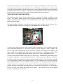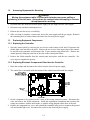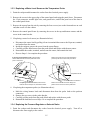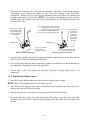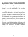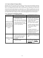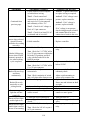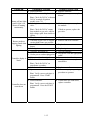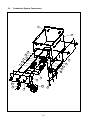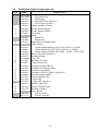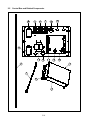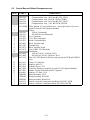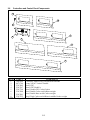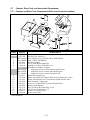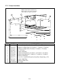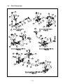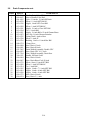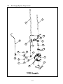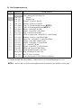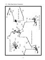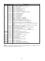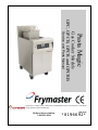
1
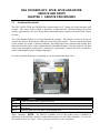
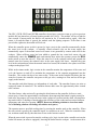
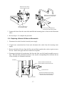
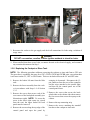
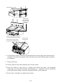
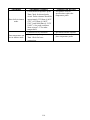
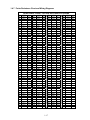
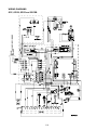
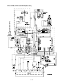
Pasta Magic
Gas Cooker Models
GPC, GPCB, GPCR and GPCRB
Service and Parts Manual
Frymaster, a member of the Commercial Food Equipment Service Association, recommends
using CFESA Certified Technicians.
24-Hour Service Hotline
1-800-551-8633
NOV 2010
*8196692*
DANGER
IMPROPER INSTALLATION, ADJUSTMENT, ALTERATION, SERVICE, OR MAINTENANCE CAN
CAUSE PROPERTY DAMAGE, INJURY, OR DEATH. READ THE INSTALLATION, OPERATING,
AND SERVICE INSTRUCTIONS THOROUGHLY BEFORE INSTALLING OR SERVICING THIS
EQUIPMENT.
DANGER
FOR YOUR SAFETY, DO NOT STORE OR USE GASOLINE OR OTHER FLAMMABLE LIQUIDS OR
VAPORS IN THE VICINITY OF THIS OR ANY OTHER APPLIANCE.
DANGER
POST IN A PROMINENT LOCATION THE INSTRUCTIONS TO BE FOLLOWED IN THE EVENT THE
USER SMELLS GAS. THIS INFORMATION SHALL BE OBTAINED BY CONSULTING THE LOCAL
GAS SUPPLIER.
THIS EQUIPMENT IS TO BE INSTALLED IN COMPLIANCE WITH THE BASIC PLUMBING CODE
OF THE BUILDING OFFICIALS AND CODE ADMINISTRATORS INTERNATIONAL, INC. (BOCA)
AND THE FOOD SERVICE SANITATION MANUAL OF THE FOOD AND DRUG ADMINISTRATION.
COMPUTERS
FCC
This device complies with Part 15 of the FCC rules. Operation is subject to the following two
conditions: 1) This device may not cause harmful interference, and 2) This device must accept
any interference received, including interference that may cause undesired operation. While
this device is a verified Class A device, it has been shown to meet the Class B limits.
CANADA
This digital apparatus does not exceed the Class A or B limits for radio noise emissions as set
out by the ICES-003 standard of the Canadian Department of Communications.
Cet appareil numerique n’emet pas de bruits radioelectriques depassany les limites de classe A
et B prescrites dans la norme NMB-003 edictee par le Ministre des Communcations du Canada.
DANGER
THIS PRODUCT CONTAINS CHEMICALS KNOWN TO THE STATE OF CALIFORNIA TO CAUSE
CANCER AND/OR BIRTH DEFECTS OR OTHER REPRODUCTIVE HARM.
Operation, installation, and servicing of this product could expose you to airborne particles of
glasswool or ceramic fibers, crystalline silica, and/or carbon monoxide. Inhalation of airborne
particles of glasswool or ceramic fibers is known to the State of California to cause cancer.
Inhalation of carbon monoxide is known to the State of California to cause birth defects or other
reproductive harm.
FRYMASTER FRYERS EQUIPPED WITH LEGS ARE FOR PERMANENT INSTALLATION. FOR
MOVEABLE OR PORTABLE INSTALLATION, FRYMASTER OPTIONAL EQUIPMENT CASTERS
MUST BE USED.
QUESTIONS??? CALL 1-800-551-8633.
Do not use deliming solution to clean water bath units. Use of deliming solution will damage all
stainless steel parts.
GAS COOKERS GPC, GPCB, GPCR and GPCRB
SERVICE & PARTS MANUAL
TABLE OF CONTENTS
CHAPTER 1: Service Procedures
1.1 Functional Description .......................................................................................................1-1
1.2 Accessing Equipment for Servicing...................................................................................1-4
1.3 Replacing Equipment Components....................................................................................1-4
1.3.1
Replacing the Controller................................................................................................1-4
1.3.2
Replacing Electronic Components Other than the Controller .......................................1-4
1.3.3
Replacing a Water-Level Sensor or the Temperature Probe .........................................1-5
1.3.4
Replacing the Pressure Regulator or Solenoid Valve....................................................1-6
1.3.5
Replacing the Water Faucet...........................................................................................1-7
1.3.6
Replacing a Basket Lift Motor or Microswitch .............................................................1-7
1.3.7
Replacing Gas Supply System Components or Ignitor Assemblies ..............................1-8
1.3.8
Replacing the Cookpot or Rinse Tank.........................................................................1-10
1.4 Troubleshooting ...............................................................................................................1-11
1.4.1
How the Power Supply System Works .......................................................................1-11
1.4.2
How the Controller Works ..........................................................................................1-11
1.4.3
How the Autofill/Autoskim System Works ................................................................1-11
1.4.4
How the Water Heating System Works.......................................................................1-12
1.4.5
How the Basket Lift System Works ............................................................................1-13
1.4.6
Technician Troubleshooting Guides............................................................................1-13
1.4.7
Probe Resistance Chart and Wiring Diagrams ............................................................1-17
CHAPTER 2: Parts List
2.1 Accessories ........................................................................................................................2-1
2.2 Basket Lift Components ....................................................................................................2-2
2.3 Cabinetry ............................................................................................................................2-4
2.4 Combustion System Components ......................................................................................2-8
2.5 Control Box and Related Components ............................................................................2-10
2.6 Controllers and Control Panel Components ....................................................................2-12
2.7 Cookpot, Rinse Tank and Associated Components .........................................................2-13
2.8 Drain Components ...........................................................................................................2-15
2.9 Gas Supply System Components .....................................................................................2-17
2.10 Water Supply Components ..............................................................................................2-19
i
GAS COOKERS GPC, GPCB, GPCR AND GPCRB
SERVICE AND PARTS
CHAPTER 1: SERVICE PROCEDURES
1.1
Functional Description
The GPC, GPCB, GPCR and GPCRB Gas Cookers all have a 12.7-gallon (48.1-liter) stainless steel
cookpot. The water in the cookpot is heated by a high-efficiency infrared heating system that
requires approximately 43% less energy than conventional burner systems to heat the same volume
of water.
Two self-contained burners are located beneath the cookpot. Each burner is fitted with special
ceramic tiles that are heated by the burning of a forced air/gas mixture. The tiles transfer their heat
to the cookpot by means of infrared radiation, providing much more constant and uniform heat
dispersion over the surface of the cookpot than do conventional burners. Because relatively less heat
is lost to the atmosphere in the process, compared to “open-burner” designs, less fuel is required to
achieve and maintain a given cookpot temperature.
Gas flow to both of the burners is regulated by one electromechanical gas valve.
Inside GPC Cabinet
Model
GPC
GPCR
GPCRB
GPCB
Description
Cooker only, auto fill/skim, programmable timer
Separate rinse tank, auto fill/skim, hot/cold water inlets, programmable timer, faucet
Automatic basket lift, separate rinse tank, auto fill/skim, hot/cold water inlets, programmable
timer, faucet
Automatic basket lifts, auto fill/skim, programmable timer
Operational control of the burner system is accomplished through a solid-state SMS III Spaghetti
Magic controller. NOTE: The SMS III controller used in this model series is identical in
appearance to the SMS III controllers used in other model series, but differs internally. Use only the
part numbers listed in Chapter 2 when replacing controllers on this equipment.
1-1
SMS III Controller
The GPC, GPCB, GPCR and GPCRB controllers do not have a ten-time warm up cycle as previous
models did, but instead use a Fenwal ignition module (807-4943). The module will try to light for
four seconds. If unsuccessful, the blower will remain on for 15 seconds and try again. Once the
burner is lit and the flame is proved, the module ends the lighting sequence. If the flame is not
proved after eight tries, the module will lock out.
When the controller power switch is pressed, a logic circuit in the controller automatically checks
the water level in the cookpot. A normally closed solenoid valve on the water supply line
automatically opens if the normal water-level sensor is not grounded by contact with water in the
cookpot. When sufficient water has been added to ground the low water-level sensor, the unit
automatically enters the SIMMER mode and remains there unless the operator presses the BOIL
mode switch or turns the unit off. When the water level in the cookpot reaches and grounds the
normal water-level sensor, the solenoid valve in the water supply line closes. Anytime the water
level in the cookpot drops below the normal water-level sensor, the solenoid valve opens to refill the
cookpot to the proper level.
While in the simmer mode, logic circuits in the controller monitor the temperature of the water and
cycle the burners on and off to maintain the temperature at the setpoint programmed into the
controller. The cooker also has a low-water safety. If the water in the cookpot falls below the low
water-level sensor, the controller cuts power to the gas valve, causing it to close and cut off the gas
supply to the burners.
The autoskim and skim features are independent of each other. The autoskim feature (on units so
equipped) cannot be turned off. The autoskim feature adds water for approximately three seconds
once a minute.
The skim feature, when activated by pressing the skim button on the controller, delivers a continuous spray of water for approximately two minutes, then stops until the button is again pressed. In
both cases, the purpose is to cause the water in the cookpot to overflow into the drain, carrying floating starch with it. (A buildup of starch reduces the efficiency of the cooker and can cause erroneous
temperature and water level sensing.) NOTE: Do not use deliming solution to clean these units.
Use of deliming solution will damage all stainless steel parts.)
The operator enters a specified cooking time by pressing the number pads on the controller. When
the start switch is pressed, the controller begins to count down to zero. When the controller times
out, an alarm sounds briefly, then the timer reverts to the last time entered.
When the start switch is pressed to start the cooking cycle, logic circuits in the controller activate the
basket lift motors (on units so equipped), lowering the basket into the cookpot. As the motors drive
1-2
the basket lift arms down, a cam attached to the left motor eventually loses contact with a rolleractivated microswitch and power to the motors are cut. When the controller times out, logic circuits
reverse the switch positions so that the motor circuit is again completed and the motors are restarted,
raising the basket from the cookpot. At the fully raised position, the cam again makes contact with
the microswitch, cutting power to the motors and stopping the lift in the up position.
THE ELECTRONIC IGNITION SYSTEM
The ignition module, located in the component box, is connected to ignitor assemblies at each
burner. The ignition module performs three important functions: it provides an ignition spark,
supplies operating voltage to the gas valve, and proofs the burner flame. The GPC series use a
Fenwal ignition module.
The ignition module contains a 4-second time delay circuit and a coil that activates the gas valve.
The ignitor assembly consists of a spark plug, an enrichment tube, and flame sensor.
Module located in box below cookpot.
At start-up, the controller power switch is placed in the ON position. If the controller senses the
correct operating parameters (i.e., the correct water level in the cookpot), it sends a signal to the
24VAC relay in the component box to close the blower contacts. This supplies line voltage to the
blower motor. A centrifugal switch in the blower closes if the blower is operating correctly, which
allows 24VAC to flow through the closed contacts of the 24VAC relay to the ignition module.
Circuitry in the ignition modules sends 24VAC to the gas valve. Simultaneously, the module causes
the ignitors to spark for 4 seconds to light the burners. A flame sensor for each burner verifies that
the burner is lit by measuring the flow of microamps through the flame. If the burner does not light
(or is extinguished), current to the ignition module is cut, preventing the gas valve from opening,
and the ignition module “locks out” until the controller power switch is turned off and then back on.
A probe monitors the temperature in the cookpot. When the programmed setpoint temperature is
reached, resistance in the probe causes the heat cycle circuitry in the controller to cut off current to
the 24VAC relay, thus cutting line voltage to the blower. This cuts the 24VAC to the ignition
module, causing the gas valve to close.
1-3
1.2
Accessing Equipment for Servicing
DANGER
Moving this equipment while it is filled with hot water may cause spilling or
splattering of the hot water. Always drain the cookpot before attempting to relocate
this equipment for servicing.
1. Disconnect the unit from the electrical power supply, the gas supply and the water supply.
2. Disconnect any attached restraining devices.
3. Relocate the unit for service accessibility.
4. After servicing is complete, reconnect the unit to the water supply and the gas supply. Reattach
the restraining devices, and reconnect the unit to the electrical power supply.
1.3
Replacing Equipment Components
1.3.1 Replacing the Controller
1. Open the control panel by removing the two screws on the bottom of the bezel. Disconnect the
trouble light wires and lower the bezel. Remove the two screws in the upper edge of the controller and lower the controller and disconnect the 15-pin connector and ground wire. Remove the
control panel by lifting the panel out of the slots in the control panel frame.
2. Remove the failed controller from the control panel and replace with the new controller. Reverse steps to complete the process.
1.3.2 Replacing Electronic Components Other than the Controller
1. Drain the cookpot and disconnect the cooker form the electrical power supply.
2. The control box is mounted inside the bottom of the cabinet located beneath the cookpot.
3. On the component to be replaced, make a note of the wiring connection points. Disconnect the
wires and remove the failed component. Install the replacement component and reconnect the
wiring in accordance with the notes made, or with the wiring diagram on the door of the unit.
4. Replace the component box cover, and reinstall the controller being sure to reconnect the ground
wire and trouble light wires. Reconnect the cooker to the electrical power supply.
1-4
1.3.3 Replacing a Water-Level Sensor or the Temperature Probe
1. Drain the cookpot and disconnect the cooker from the electrical power supply.
2. Remove the screws in the upper edge of the control panel and swing the panel down. Disconnect
the 15-pin connector, trouble light wires, and ground wire, and lift the panel out of the slots in
the control panel frame.
3. Remove the topcap from the unit by removing the four screws (two on the front and two on each
end) that secure it to the cabinet.
4. Remove the control panel frame by removing the screws in the top and bottom corners and the
screw in the center bracket.
5. If replacing a water-level sensor (see illustration below):
a. Disconnect the sensor lead by pulling it from its terminal then remove the Keps nut, terminal,
and washer from the sensor.
b. Inside the cookpot, remove the screw from the sensor flange.
c. Carefully pull the failed sensor from the probe block and replace with the new sensor.
d. Reassemble the washer, terminal, and nut onto the sensor, and reattach the lead.
e. Reverse Steps 1-4 to complete the procedure.
If replacing the temperature probe, mark the wiring
harness leads and disconnect the probe leads at the
push on connectors.
Remove the screws from the probe bracket and
push the probe out the back of the probe block.
Temperature Probe
Water-Level Sensors
If replacing a water-level sensor, disconnect its
lead and remove its Keps nut, terminal and washer.
Remove the screw from the sensor flange and
pull the sensor out the front of the probe block.
6. If replacing the temperature probe (see illustration above):
a. Mark the wiring harness leads and disconnect them from the probe leads at the push-on
connectors.
b. Remove the two screws in the probe bracket.
c. Carefully pull the probe from the probe block and replace with the new probe.
d. Reattach the leads and reverse Steps 1-4 to complete the procedure.
1.3.4 Replacing the Pressure Regulator or Solenoid Valve
1. Drain the cookpot and disconnect the cooker from the electrical power supply. Turn off or
disconnect the water supply to the cooker.
1-5
2. Disconnect the solenoid leads at the push-on connectors. Disconnect solenoid and regulator
subassembly at the compression fittings on the water lines running to and from these
components. Remove the two screws in the mounting bracket and remove the solenoid and
regulator subassembly from the unit. (NOTE: If the cooker is not equipped with the optional
Autofill feature, the cookpot water tube will be connected directly to the regulator and there will
be no solenoid valve.)
The incoming water line will be connected
to the nipple at the inlet side of the
regulator using some type of field
connection fitting. Whatever type fitting is
used, disconnect the regulator at this point.
Remove the two screws
at the bottom of this
bracket to dismount the
solenoid and regulator
sub-assembly.
Solenoid Valve
Remove the two
screws at the
bottom of this
bracket to
dismount the
solenoid and
regulator subassembly.
Solenoid Valve
Disconnect the water
tubes at these
compression fittings.
GSMS with Autofill Configuration
Disconnect the water tube
at this compression fitting.
GBC/GC with Autofill Configuration
3. If replacing the regulator, adjust the replacement regulator output pressure to not more than 40
PSI (28.15 kg/cm2) before installation in the cooker.
4. Recover the fittings from the failed component (regulator or solenoid valve) and install them on
the replacement, using thread sealer on all connections.
5. Reverse Steps 1 and 2 to complete the procedure, being sure to apply thread sealer to all
connections.
1.3.5 Replacing the Water Faucet
1. Drain the cookpot and disconnect the cooker from the electrical power supply.
NOTE: Refer to the illustration below for the following steps.
2. Turn off the water supply to the cooker and disconnect the incoming water lines where they
attach to the stubs at the rear of the cooker.
3. Remove the two screws securing the access panel in place and remove the panel.
4. Disconnect the water supply line at the compression fitting where it attaches to the water inlet
manifold. Remove the screws from the faucet mounting plate and lift the faucet assembly from
the unit.
1-6
Remove the six screws in
the faucet mounting plate.
Remove this nut to separate the
faucet from the mounting plate.
Disconnect water line at
this compression fitting.
Loosen this nut to separate the
faucet from the water inlet manifold.
5. Separate the faucet from the water inlet manifold and mounting plate as shown in the illustration
above.
6. Reverse Steps 1-5 to complete the procedure.
1.3.6 Replacing a Basket Lift Motor or Microswitch
1. Disconnect the cooker from the electrical power supply.
2. If rigid water connections have been used, disconnect the cooker from the incoming water
supply.
3. Remove the basket lift arms from the lifter rods and then reposition the cooker to gain access to
the rear. Remove the upper and lower basket lift rear panels.
4. Disconnect the basket lift synchronizer link from the lifter cam (bell crank) assemblies one at a
time. When the link is disconnected from a cam, slip the corresponding lifter rod down and out
of the assembly (see illustration on below).
Lifter Rods
Note the collection of washers and
spacers between the link and lifter rods.
Synchronizer Link
Disconnect the basket lift synchronizer
link from the lifter cams and slip the lifter
rods down and out of the assembly.
Lifter Cams
1-7
5. Remove the four bolts securing the motor mount to the frame, then remove the “motor and
mount assembly” from the unit. NOTE: It is possible to replace a motor or the microswitch
without removing the “motor and mount assembly”, but it is much more difficult.
6. Dismount the motor or microswitch as shown below and install the replacement.
NOTE: The right motor dismounts
in the same way as the left.
Loosen setscrew in
bottom of cam (bell crank)
7. Reverse Steps 1-6 to complete the procedure.
1.3.7 Replacing Gas Supply System Components or Ignitor Assemblies
1. Disconnect the cooker from the electrical power supply and from the gas supply. If necessary,
disconnect restraints to gain proper access to components.
2. Disconnect the component to be replaced (see illustration below) and install the replacement
component. NOTE: If replacing the gas valve, disconnect the enrichment tubes and gas supply
tubes at the valve, then unscrew the valve from the mounting bracket. Recover the fittings from
the failed valve and install them on the replacement valve using a thread sealer suitable for gas
appliances (Loctite™ PST 56765 is one example). Do not apply the sealer to the first two
threads of the fitting. This will help prevent clogging of the burner orifices and gas valve.
1-8
Burners
Blower and plenum
removed
3. Reconnect the cooker to the gas supply and check all connections for leaks using a solution of
soapy water.
DANGER
DO NOT use matches, candles, or other ignition methods to check for leaks.
4. When satisfied that there are no leaks, reconnect the unit to the electrical supply, and reconnect
any restraints disconnected in Step 1.
1.3.8 Replacing the Cookpot or Rinse Tank
NOTE: The following procedure addresses removing the cookpot or rinse tank from a GPC unit.
The procedure is essentially the same for a GPC, GPCB, GPCR and GPCRB units, except that there
is no faucet on the GC, GPC or GPCB units. There are no basket lifts on the GC and GPC units.
swinging it downward. Disconnect the 15pin connector from the rear of the controller
and the wires attached to the trouble light,
and then lift the control panel out of the
control panel frame.
1. Remove the basket lift arms from the lifter
rods.
2. Remove the faucet assembly from the cooker in accordance with Steps 1-4 of Section
1.3.5.
3. Remove the screws that secure each of the
rear corners of the backsplash assembly (see
illustration at right). NOTE: To access the
screw in the lower right corner (as viewed
from the rear) the upper basket lift back
panel must be removed.
4. Remove the screws along the top edge of the
control panel and open the panel by
5. Remove the screws that secure the backsplash sides to the cabinet sides then remove
the four screws that secure the topcap to the
cabinet.
6. Remove the top connecting strip.
7. Remove the screws attaching the standoff
brackets to the cookpot or rinse tank.
1-9
Remove these four screws.
Remove these
screws (on both
sides) and remove
backsplash and
topcap.
Remove screws along the top edge of
control panel and dismount the panel.
Remove these screws to release
the pots from the standoff brackets.
Remove the top
connecting strip.
8. If removing the cookpot, disconnect the enrichment tubes and gas supply tubes from the burner
assemblies. Disconnect the ignition cables and flame sensor wires from the ignitor assemblies
on each burner.
9. Remove the blower.
10. Lift the cookpot or rinse tank straight up and out of the cabinet.
11. Invert the cookpot or rinse tank on a suitable work surface and remove the salvageable
components (e.g., probe block assembly, drain plumbing, etc.). Install the recovered components
on the replacement cookpot or rinse tank, using thread sealer on all connections.
12. Reverse Steps 1 through 9 to complete the procedure.
1-10
1.4
Troubleshooting
Problems with this equipment maybe grouped into five broad categories:
1.
2.
3.
4.
5.
Failure or malfunction of a Power-Supply System component.
Failure or malfunction of the Controller.
Failure or malfunction of an Autofill/Autoskim System component.
Failure or malfunction of a Water Heating System component.
Failure or malfunction of a Basket Lift System component.
Sections 1.4.1 through 1.4.5 briefly explain the functioning of each of the systems mentioned above.
Section 1.4.6 contains troubleshooting guides that provide systematic procedures to isolate and
identify the specific source of a problem. A wiring diagram is located at the end of the chapter.
1.4.1 How the Power-Supply System Works
Line voltage is supplied to the system via a power cord that is plugged or hard-wired into the store’s
electrical service. The power cord is connected to pins 1 and 5 of an 8-pin terminal block. Line voltage is supplied to a 24VAC transformer from pins 2 and 8 of the terminal block. Pin 7 supplies
24VAC to a heat relay, which controls line voltage to the blower motor and 24VAC to the gas valve
via the ignition module. The transformer supplies 24VAC to the controller, to the coils of the
24VAC relay, and to the solenoid valve on units equipped with the Autofill option. On units
equipped with basket lifts, line voltage is supplied to a 24VDC basket lift relay from pin 6 of the
power cord terminal block. Line voltage to the basket lift motors is supplied via the basket lift relay.
1.4.2 How the Controller Works
The SMS III controller provides the interface between the operator and the system components. The
controller is powered by 24VAC supplied through pins 1 and 2 of the wiring harness. Internal circuitry senses the water level and water temperature. Depending upon the conditions sensed, the controller energizes or de-energizes the solenoid valve which controls the water level. The 24VAC relay controls burner firing which controls water temperature. The controller also controls the lowering and raising of the basket lift, and activates an audible alarm to signal the operator that a cooking
cycle has completed. A rectifier in the controller converts 24VAC to the 24VDC required by the
basket lift relay. The controller signals for heat via pin 4, grounds the solenoid valve via pin 6, and
senses water level via pins 7 (low) and 9 (full). The temperature probe connects to pins 13 and 14.
The basket lift relay connects to pins 10 and 12. The sound device connects to pin 11.
1.4.3 How the Autofill/Autoskim System Works
The heart of the automatic filling (Autofill) system is a normally closed solenoid valve that opens
when 24VAC is applied.
The ground for the solenoid is supplied (via pin 6 of the controller wiring harness) so long as the
shorter of the two water-level sensors is not in contact with the water in the cookpot. When the
water in the cookpot reaches the shorter of the two water-level sensors, the sensor is grounded. This
causes the controller to break the solenoid ground, closing the valve. Starch or lime build-up on the
sensor may keep it from grounding, therefore always make sure the sensor is clean and its lead (pin 9
of the controller wiring harness) is firmly connected. Also, in order for the sensor to ground, there
must be some mineral content in the water (pure water is non-conductive). Consequently, the unit
will not operate correctly with distilled, highly filtered, or deionized water. If water of these types is
1-11
used, add ⅛-cup of baking soda to the water each time the cookpot is emptied and refilled. NOTE:
Do not use deliming solution to clean these units. Use of deliming solution will damage all stainless
steel parts.)
On units equipped with the Autoskim feature, a logic circuit in the controller automatically opens the
solenoid valve for three seconds every minute. If the autofill feature is working properly, failure of
the autoskim feature will be due to a malfunctioning controller and not the solenoid valve. (Proper
operation of the autofill feature can be determined by draining water from the cookpot until the
water level is below the shorter of the two water-level sensors. If the solenoid valve opens and then
closes when the water in the cookpot again reaches the sensor, the autofill feature is working
properly.)
1.4.4 How the Water Heating System Works
To prevent lighting the burners when there is no water in the cookpot, these units are equipped with
a low-water-level sensor (the longer of the two water-level sensors). This sensor must be grounded
by contact with water in the cookpot before the control circuitry will allow firing of the burners.
Starch or lime build-up on the low-water-level sensor may keep the sensor from grounding, therefore
always make sure the sensor is clean and its lead (Pin 7 of the controller wiring harness) is firmly
connected. Also, in order for the sensor to ground, there must be some mineral content in the water
(pure water is non-conductive). Consequently, the unit will not operate correctly with distilled,
highly filtered, or deionized water. If water of these types is used, add ⅛-cup of baking soda to the
water each time the cookpot is emptied and refilled. NOTE: Do not use deliming solution to clean
these units. Use of deliming solution will damage all stainless steel parts.)
In addition to the low-water-level sensor discussed above, the water heating system has three more
parts: the electronic ignition system, the temperature probe, and the controller.
The electronic ignition system controls firing of the burners.
description of this system.
See Page 1-3 for a complete
The temperature probe is used only when the unit is in the simmer mode. When the simmer mode
is selected, logic circuits in the controller monitor the temperature of the water. When the water
temperature drops below the simmer setpoint, the controller closes the heat relay, causing the
burners to fire. When the water temperature reaches the setpoint, the controller opens the heat relay,
extinguishing the burners. This process repeats as required to maintain the temperature at the
setpoint programmed into the controller.
The controller is the interface between the operator and the other components of the equipment. In
the water heating system, its function is to control the firing of the burners.
1-12
1.4.5 How the Basket Lift System Works
When the start switch is pressed to start the cooking cycle, logic circuits in the controller activate the
basket lift motors, lowering the basket into the cookpot. As the motors drive the basket lift arms
down, a cam attached to the left motor (when viewed from the rear) eventually loses contact with a
roller-activated microswitch and power to the motors is cut. When the controller times out, logic
circuits reverse the switch positions so that the motor circuit is again completed and the motors are
restarted, raising the basket from the cookpot. At the fully raised position, the cam again makes contact with the microswitch, cutting power to the motors and stopping the lift in the raised position.
1.4.6 Technician Troubleshooting Guides
PROBLEM
Autofill does not add
water when water
level is below the
normal water-level
sensor (the shorter of
the two water-level
sensors).
PROBABLE CAUSES
A. Water not turned on.
B. Failed solenoid, failed computer,
or loose/broken wiring.
CORRECTIVE ACTION
A. Turn on Water
B. If voltage is present at solenoid
end of wire 66C, and Pin 6 of
15-pin connector is grounded (0
Test: Check for at least 22VAC at
voltage present), check
Pin 5 of the 24VAC terminal block
continuity of wire 50C. If wire
and at solenoid end of wire 66C,
50C is good, replace solenoid.
and check for ground (0 voltage) at
If voltage is present at solenoid
pin 6 of 15-pin connector.
end of wire 66C and at Pin 6 of
15-pin connector, replace
controller.
If voltage is not present at
solenoid end of wire 66C, check
wiring between solenoid and
terminal block for loose
connection or break in the wire.
A. Starch accumulation on the normal A. Clean the water-level sensors.
water-level sensor (the shorter of
NOTE: Do not use deliming soluthe two water-level sensors) is
tion.
preventing the sensor from
Autofill does not shut
grounding.
off when the cookpot
is full.
B. Mineral content of water is too low B. Add 1/8th cup of baking soda to
to provide a ground.
water in cookpot. DO NOT
USE SALT! Doing so will
damage the cookpot.
1-13
PROBLEM
PROBABLE CAUSES
C. Failed solenoid, failed computer,
or broken/loose wiring.
Continued from
previous page.
Test 1: Check sensor-lead
connections on outside of cookpot
and at pin 9 of 15-pin connector
and continuity of wire 71C.
Test 2: Check for AC voltage at
Pin 6 of 15-pin connector.
Test 3: Check for at least 22VAC
at solenoid end of wire 66C.
Autoskim does not add
water when selected
(Autofill feature
A. Failed controller.
verified to be working
correctly).
A. Failed basket lift relay.
CORRECTIVE ACTION
C. Action 1: Tighten connections
or replace wiring as required.
Action 2: If AC voltage is not
present, replace controller.
Action 3: If AC voltage is
present, replace solenoid.
If AC voltage is not present,
check wiring between solenoid
and terminal block for loose
connection or break in the wire.
A. Replace controller.
A. If voltages are correct, replace
relay.
Test: Check for 13-17VDC at Pin
10 of 15-pin connector with basket
lift in the UP position, and for 0
volts with the basket lift in the
DOWN position.
Failed controller.
B. Replace controller if voltage is
below 12VDC.
Test: Check for 13-17VDC at Pin
12 of 15-pin connector.
A. Failed or out of adjustment
A. Replace switch if it fails
Basket lift travels up
microswitch.
continuity check.
and down
Adjust switch mounting to
Test: Check continuity of switch
continuously.
ensure roller contacts cam.
and verify that roller contacts cam.
A. Bell crank slipping on shaft.
A. Tighten bell crank setscrew.
Ensure nut and locknut on shaft
Basket lift travels
are tight.
erratically or with
B. Lift arms binding in bushings
B. Lubricate lift arms.
jerking motion.
C. Defective motor.
C. Replace motor.
Burner attempts to A. Flame sensor wire and ignitor
A. Verify that sense 1 and spark 1
light but will not
cables crossed.
connect to same ignitor.
remain lit.
A. Cooker gas valve is turned off.
A. Turn gas valve on.
Burner will not light;
B. Incoming gas line shut-off valve is B. Open incoming gas line shut-off
trouble light is on.
closed.
valve.
A. If voltage is present, replace
Burner will not light; A. Failed 24VAC (blower) relay.
relay.
trouble light is not on,
Test: Check for 24VAC on pin 4
blower is not running.
of 15-pin connector.
Basket lift does not
lower when START
button is pressed or
rise when cooking
cycle completes.
B.
1-14
PROBLEM
PROBABLE CAUSES
B. Failed controller.
A. Failed blower centrifugal switch.
CORRECTIVE ACTION
B. Replace controller.
A. If voltage is not present, replace
blower.
Test: Check for 24VAC at bottom
24VAC terminal of ignition
module (wire 7C).
Burner will not light;
trouble light is on, B. Failed ignition module or gas
B. If either is not present, replace
blower is running
valve.
the module.
continuously.
If both are present, replace the
Test: Check for 24VAC output
gas valve.
from module to gas valve, and for
high voltage spark from module to
ignitor.
A. Dirty blower inlet and fan.
A. Clean blower.
B. Vent tube on gas valve is clogged, B. Remove and clean vent tube.
Burner produces
causing high burner gas pressure.
popping sound when
C. Cracked/broken ceramic tiles in
C. Replace burner.
lighting.
burner.
D. Failed ignitor.
D. Replace ignitor.
A. Controller not turned on.
A. Turn on controller.
B. Plug power cord into appropriate
B. Cooker power cord not plugged in.
outlet.
C.
Main
circuit
breaker
tripped.
C.
Reset main circuit breaker.
Controller display is
D. Failed transformer.
D. If voltage is incorrect, replace
blank.
transformer.
Test: Check for 24VAC on
transformer secondary.
E. Failed controller.
E. Replace controller.
A. Operator error.
A. Demonstrate proper operating
procedure to operator.
Test: Verify correct cook time is
programmed. Press START
button.
B. If timer does not count down,
B. Failed controller.
replace controller.
Test: Verify correct cook time is
Controller does not
programmed. Press the START
count down.
button.
1-15
PROBLEM
PROBABLE CAUSES
CORRECTIVE ACTION
A. Failed/shorted temperature probe. A. If resistance is out of
specification, replace the
Test: Check for shorted probe
temperature probe.
circuit. Probe resistance should be
approximately 552 Ohms @ 60°F
Water boils in simmer
(16°C), 655 Ohms @ 100°F
mode.
(38°C), and 1000 Ohms @ 212°F
(100°C). See probe resistance
chart on page 1-17 for other
temperatures.
A. Controller out of calibration
A. Recalibrate simmer setpoint.
B. If connections are secure, reWater temperature too B. Temperature probe open.
place temperature probe.
low in simmer mode.
Test: Check for loose
connections.
1-16
1.4.7 Probe Resistance Chart and Wiring Diagrams
RESISTANCE CHART FOR USE WITH 806-4764 PROBE
F
OHMS
C
F
OHMS
C
F
OHMS
C
F
OHMS
C
32
33
34
35
36
37
38
39
40
41
42
43
44
45
46
47
48
49
50
51
52
53
54
55
56
57
58
59
60
61
62
63
64
65
66
67
68
69
70
71
72
73
74
75
76
77
78
79
80
81
82
486.0
488.3
490.5
492.8
495.1
497.4
499.7
502.0
504.3
506.6
509.0
511.3
513.6
516.0
518.3
520.7
523.1
525.4
527.8
530.2
532.6
535.0
537.4
539.8
542.2
544.7
547.1
549.5
552.0
554.4
556.9
559.4
561.8
564.3
566.8
569.3
571.8
574.3
576.8
579.3
581.8
584.4
586.9
589.4
592.0
594.5
597.1
599.7
602.3
604.8
607.4
0.0
0.6
1.1
1.7
2.2
2.8
3.3
3.9
4.4
5.0
5.6
6.1
6.7
7.2
7.8
8.3
8.9
9.4
10.0
10.6
11.1
11.7
12.2
12.8
13.3
13.9
14.4
15.0
15.6
16.1
16.7
17.2
17.8
18.3
18.9
19.4
20.0
20.6
21.1
21.7
22.2
22.7
23.3
23.9
24.4
25.0
25.6
26.1
26.7
27.2
27.8
83
84
85
86
87
88
89
90
91
92
93
94
95
96
97
98
99
100
101
102
103
104
105
106
107
108
109
110
111
112
113
114
115
116
117
118
119
120
121
122
123
124
125
126
127
128
129
130
131
132
133
610.0
612.6
615.2
617.8
620.5
623.1
625.7
628.4
631.0
633.7
636.3
639.0
641.7
644.3
647.0
649.7
652.4
655.1
657.8
660.6
663.3
660.0
668.8
671.5
674.3
677.0
679.8
682.6
685.3
688.1
690.9
693.7
696.5
699.3
702.1
705.0
707.8
710.6
713.0
716.3
719.2
722.1
724.9
727.8
730.7
733.6
736.5
739.4
742.3
745.2
748.1
28.3
28.9
29.4
30.0
30.6
31.1
31.7
32.2
32.8
33.3
33.9
34.4
35.0
35.6
36.1
36.7
37.2
37.7
38.3
38.9
39.4
40.0
40.6
41.1
41.7
42.2
42.8
43.3
43.8
44.4
45.0
45.6
46.1
46.7
47.2
47.8
48.3
48.9
49.4
50.00
50.6
51.1
51.7
52.2
52.8
53.3
53.9
54.4
55.0
55.6
56.1
134
135
136
137
138
139
140
141
142
143
144
145
146
147
148
149
150
151
152
153
154
155
156
157
158
159
160
161
162
163
164
165
166
167
168
169
170
171
172
173
174
175
176
177
178
179
180
181
182
183
184
751.0
754.0
756.9
759.9
762.8
765.8
768.8
771.7
774.7
777.7
780.7
783.7
786.7
789.7
792.7
795.8
798.8
801.8
804.9
807.9
811.0
814.1
817.1
820.2
823.3
826.4
829.5
832.6
835.7
838.8
842.0
845.1
848.2
851.4
854.5
857.7
860.8
864.4
867.2
870.4
873.6
876.8
880.0
883.2
886.4
889.6
892.8
896.1
899.3
902.6
905.8
56.7
57.2
57.8
58.3
58.9
59.4
60.0
60.5
61.1
61.7
62.2
62.8
63.3
63.9
64.4
65.0
65.6
66.1
66.7
67.2
67.8
68.3
68.9
69.4
70.0
70.6
71.1
71.7
72.2
72.8
73.3
73.9
74.4
75.0
75.6
76.1
76.7
77.2
77.8
78.3
78.9
79.4
80.0
80.6
81.1
81.7
82.2
82.8
83.3
83.9
84.4
185
186
187
188
189
190
191
192
193
194
195
196
197
198
199
200
201
202
203
204
205
206
207
208
209
210
211
212
909.1
912.4
915.6
918.9
922.2
925.5
928.8
932.1
935.4
938.7
942.1
945.4
948.8
952.1
955.5
958.8
962.2
965.6
968.9
972.3
975.7
979.1
982.5
985.9
989.4
992.8
996.2
999.7
85.0
85.7
86.1
86.7
87.2
87.8
88.3
88.9
89.4
90.0
90.6
91.1
91.7
92.2
92.8
93.3
93.9
94.4
95.0
95.6
96.1
96.7
97.2
97.8
98.3
98.9
99.4
100.0
1-17
WIRING DIAGRAMS
GPC, GPCB, GPCR and GPCRB
1-18
GPC, GPCB, GPCR and GPCRB (Noodles)
1-19
GPC, GPCB, GPCR and GPCRB (CE)
1-20
PASTA MAGIC GAS COOKERS GPC, GPCB, GPCR AND
GPCRB SERVICE AND PARTS
CHAPTER 2: PARTS LIST
2.1 Accessories
5
1
2
6
7
4
3
8
ITEM
PART #
1
803-0018
2
810-2229
3
803-0205
4
806-5848SP
5
809-0985
6
823-1910
7
826-0900
8
823-7880
*
803-0200
*
803-0238
* Not illustrated.
COMPONENT
Cup, Single Pasta Portion (Beige)
Hanger, Wire-Form Basket
Rack, Support
Kit, Hose (Swirl and Straight w/Fittings)
Thumbscrew, ¼-20 x 1⅛
Basket, GSMS Bulk
Kit, Chain Restraint
Strip, Top Connecting
Rack, 12 Portion Cup
Basket, 5½ x 8½ SS Round Pasta
2-1
2.2 Basket Lift Components
11
DETAIL A
33
27
13
31
29
4
16
41
23
35
16
20
39
21
38
SEE DETAIL A
28
9
24
32
5
37
12
44
6
26
1
2
8
14
42
10
34
3
19
40
25
43
36
30
22
18
17
19
7
18
2-2
15
2.2
Basket Lift Components cont.
ITEM
PART #
1
2
3
4
5
6
7
8
9
10
11
12
13
14
15
16
17
18
19
20
21
22
23
24
25
26
27
28
29
30
31
32
33
34
35
36
37
38
39
40
41
42
43
44
807-0107
807-0108
807-0124
807-0240
809-0047
826-1358
809-0050
809-0063
809-0076
809-0082
809-0097
826-1363
809-0113
809-0127
826-1370
809-0155
809-0190
809-0196
809-0200
826-1381
809-0247
826-1374
809-0480
809-0508
813-0035
810-0052
810-0170
810-0172
810-0192
810-0194
810-0220
810-0374
812-0138
823-2007
900-7416
900-7418
900-7419
220-7177
901-1927
902-1927
910-4525
910-7420
911-7417
912-7417
920-6076
COMPONENT
Motor, Basket Lift
120 VAC
240 VAC
Bushing, Plastic
Microswitch, BA-2RV22-D6
Nut, ¼-20 Hex Head Cap
Nut, 6-32 Hex Head (Pkg. of 25)
Nut, 8-32 Hex Head
Nut, ¾-inch Jam
Nut, ¼-20 Expansion
Ring, Retaining (secures Item 24 in place)
Screw, 6-32 x 1-inch Slotted Truss Head
Screw, 8-32 x ½-inch Slotted Truss Head (Pkg. of 25)
Screw, 8-32 x 1½-inch Slotted Truss Head
Screw, ¼-20 x ½-inch Slotted Round Head
Screw, ¼-20 x 1½-inch Slotted Round Head
Screw, Leveling
Washer, ¼-inch SS Flat
Washer, ⅜-inch Flat
Washer, ¼-inch Flat
Washer, ½-inch Nylatron (Pkg. of 10)
Nut, 8-32 Hex Head Keps
Screw, #10 x ½-inch Hex Head (Pkg. of 25)
5
Setscrew, ¼-28 x ⁄8-inch (secures Item 25 to motor shaft)
Bolt, ¼-20 x ¼-inch SS AT Hex Head
Bushing, .875 Hole
Bellcrank (Cam)
5
Pin, ¼-inch x ⁄8-inch Spring Dowel
Button, Plug
Rod, Basket Lift
Roller, Basket Lift
Spacer, .493-inch x .200-inch Tubular
Spacer, Basket Lift Roller Tubular
Insulation, Paper
Arm Assembly, Basket Lift (Use 823-7061 for Stainless)
Mount, Basket Lift Motor
Back, Upper Basket Lift Enclosure (Use 210-8297 for Stainless)
Back, Lower Basket Lift Enclosure (Use 230-3762 for Stainless)
Support, Basket Lift Center
Bracket, Left Basket Lift Roller
Bracket, Right Basket Lift Roller
Bar, Basket Lift Synchronizing
Top, Basket Lift Enclosure
Side, Basket Lift Enclosure (Use 231-3764 for Stainless)
Side, Basket Lift Enclosure (Use 232-3764 for Stainless)
Link, Basket Lift
NOTE: Order KIT0004SP to add a complete basket lift assembly to a GC unit.
2-3
2.3
Cabinetry
2.3.1 GPC/GPCB
2-4
2.3.1 GPC/GPCB cont.
ITEM
PART #
1
A
2
3
4
*
5
6
*
7
8
9
10
11
12
13
14
15
16
17
18
19
20
21
22
23
24
25
26
27
28
108-1434
106-4067
826-1343
230-4963
809-0193
826-1371
230-7192
230-4685
108-1413
806-5209SP
900-4655
900-7528
220-6976
200-5095
826-1119
810-1105
816-0091
900-4651
900-1552
900-1940
900-1759
900-1932
900-4654
824-2120
809-0266
108-1426
816-0158
900-4521
108-1424
823-7592
816-0169
910-1181
809-0053
826-1351
108-1485
108-1825
108-1826
812-1141
826-1374
812-1142
900-4645
COMPONENT
Door Assembly, 18.66-inch x 19.85-inch (does not include handle)
Door Pin Assembly
Spring, Door Hinge (Pkg. of 10)
Handle, Wireform Door
Washer, ¼-inch Nylon Flat
Screw, #8 x ½-inch Drill Point Hex Head Zinc Plated (Pkg. of 25)
Hinge, Universal Door
Hinge, Lower
Base Assembly, GPC/GC SS (Use 108-1414 CR for GPCB)
Leg Pad Assembly
Channel, Front or Rear Base
Channel, Left or Right Base
Shield, GBC/GC Vapor (See NOTE below)
Shield, Vapor (for units with manual water fill)
Leg Assembly w/Mounting Hardware
Magnet, Door
Side, Left or Right Cabinet
Stainless Steel (Use 231-6969 Left or 232-6969 Right)
Enameled Mild Steel (Use 221-6966 Left or 222-6966 Right)
Grommet, 1¼-inch Drain
Shield, Control Box Water
Gusset
Bracket, Control Box Mounting
Bracket, Pot Hold-Down
Retainer, Flue Insulation
Brace, Front or Rear Top
Topcap
Screw, #10 x ½-inch Philips Truss Head Zinc Plated
Frame Assembly, Control Panel
Insulation, 18.25-inch x 10.7-inch x .25-inch Cabinet Back
Retainer, Cabinet Back Insulation
Flue Cap and Insulation Assembly
Flue Cap
Insulation, 8.12-inch x 18-inch x .25-inch Flue Cap
Retainer, Flue Cap Insulation
Nut, 10-32 Hex
Nut Retainer, ¼-20 (Nutsert) (Pkg. of 10)
Back, GPC Single Cabinet CR (Use 108-1432 for Stainless)
Back, Upper GPC Single Cabinet Noodle’s
Back, Lower GPC Single Cabinet Noodle’s
Insulation, Cabinet Back
Screw, #10 x ½-inch Hex Head (Pkg. of 25)
Insulation, Cabinet Back
Shield, Basket Lift Heat
* Not illustrated.
2-5
2.3.2 GPCR/GPCRB Batteries
2-6
2.3.2 GPCR/GPCRB Batteries cont.
ITEM
PART #
COMPONENT
Cabinet Assemblies
108-2146
Double GPC Cooker/Cooker Stainless (Use 108-2154 for CR)
108-1831
Double Cooker on left/Rinse on right (Use 108-1832 for CR)
108-1838
Double Rinse on left/Cooker on right (Use 108-1839 for CR)
108-1976
Triple Cooker on left/Rinse in middle/Cooker on right (Use 108-1977
for CR)
1
Topcap
824-2168
Double GPC Cooker/Cooker
824-2143
Double Cooker on left/Rinse on right
824-2144
Double Rinse on left/Cooker on right
824-2154
Triple Cooker on left/Rinse in middle/Cooker on right
2
Control Panel Assembly, GPC
108-2149
Double GPC Cooker/Cooker
108-1844
Double Cooker on left/Rinse on right
108-1845
Double Rinse on left/Cooker on right
108-1981
Triple Cooker on left/Rinse in middle/Cooker on right
3
Bezel
230-7798
Double GPC Cooker/Cooker
230-7400
Double Cooker on left/Rinse on right
230-7401
Double Rinse on left/Cooker on right
230-7555
Triple Cooker on left/Rinse in middle/Cooker on right
4
231-6969
Side, Left Cabinet Stainless (Use 221-6966 for CR)
5
232-6969
Side, Right Cabinet Stainless (Use 222-6966 for CR)
6
108-0577
Door Assembly (does not include item #7) used on all except triple middle.
106-4067SP
Door Pin Assembly
826-1343
Spring, Door Hinge (Pkg. of 10)
108-1434
Door Assembly (does not include item #7) used only on triple middle door
7
230-4963
Handle, Door
8
230-7192
Hinge, Universal Door
9
826-1118
Caster w/Brake (includes mounting hardware)
10
826-1117
Caster w/o Brake (includes mounting hardware)
11
220-7182
Shield, Basket Lift Heat
12
Back, Cabinet, GPC
108-2147
Double GPC Cooker/Cooker (Use 108-2155 for CR)
108-1833
Double Cooker on left/Rinse on right (Use 108-1835 for CR)
108-1840
Double Rinse on left/Cooker on right (Use 108-1841 for CR)
108-1833 &
Triple Cooker on left/Rinse in middle/Cooker on right (Use 108-1835 &
108-1432
108-1485 for CR)
13
Flue Cap Assembly
108-2148
Double GPC Cooker/Cooker
108-1842
Double Cooker on left/Rinse on right
108-1843
Double Rinse on left/Cooker on right
108-1978
Triple Cooker on left/Rinse in middle/Cooker on right
14
230-7396
Mount, Faucet
15
810-1105
Magnet, Door
2-7
2.4
Combustion System Components
2-8
2.4
Combustion System Components cont.
ITEM
PART #
COMPONENT
Cookpot Complete Assemblies (does not include burner (see item 20))
108-1420SP
GPC Natural Gas
108-1422
GPC Propane
108-1655
GPC Natural Gas (Noodle’s)
108-1656
GPC Propane (Noodle’s)
1
108-1419 Support Assembly, Plenum
2
220-6994 Bracket, Retainer Burner
3
220-6995 Bracket, Support Plenum
4
807-0037 Tab, Faston
5
Ignitor
826-0981
Natural Gas
826-0982
Propane Gas
6
826-1072 Burner, Universal Replacement
Orifice, Burner
*
810-0386
2.10mm Propane/Butane (G30,G31) (0-4999 Ft., 0-1524M)
*
810-0403
3.40mm Natural Gas (G20, G25) (0-4999 Ft., 0-1524M)
*
810-0437
3.60mm Natural Gas(G20, G25) (5000 – 6999Ft., 1525-2133M)
7
810-0976 Nozzle, Water Inlet (Noodle’s)
8
812-0357 Insulation, Burner
9
814-0048SP Glass, Site
10
816-0053 Insulation, Site Glass
11
816-0057 Gasket, Plenum H50
*
816-0145 Insulation, Pot Side FBR 18
*
816-0155 Insulation, Rear Bottom GSMS
12
816-0152 Insulation, Front SMSG
13
816-0153 Insulation, 10x24x.25 GSMS Cookpot Side
14
816-0059 Insulation, Ignitor GSMS
15
823-7591 Plenum Assembly GPC
16
823-7590 Cookpot GPC
823-7629 Cookpot GPC (Noodle’s)
17
900-1031 Retainer, Sight Glass
18
900-1049 Retainer, Plenum Gasket
19
900-1762 Insulation, Retainer
20
Motor, Blower
108-1540
120VAC/60 Hz
807-1712
230VAC 50/60 Hz
*Not illustrated.
2-9
2.5
Control Box and Related Components
2-10
2.5
Control Box and Related Components cont.
ITEM
PART #
COMPONENT
Component Assembly Boxes
108-1506
Component Box Assy, 120V Non-BL GPC, GPCR
108-1625
Component Box Assy, 120V BL GPCB, GPCRB
108-1546
Component Box Assy, 230V Non-BL GPC, GPCR
108-1626
Component Box Assy,, 230V BL GPCB, GPCRB
1
106-3338SP Cable, Ignition 36” (used with Item 16 – also requires Item 15) (two required for each 807-4943 Ignition Module)
2
Cordset
108-1541
120VAC (illustrated)
108-1547
208-240VAC (not illustrated)
3
220-7051 Box, Component
4
220-7052 Cover, Box Component
5
220-7053 Mount, Component Box
6
807-0067 Block, Terminal 8 pin
7
807-0255 Terminal Strip
8
807-0276 Block, Terminal 20-pin
9
807-0670 Relay, DPDT 24V Heat Relay
10
Transformer
807-0800
120VAC/24VAC, 50/60 Hz, 50VA
807-0680
208-240VAC/24VAC, 50/60 Hz, 20VA
11
807-1396 Relay 24V SPST Basket Lift Relay (only present in GPCB and GPRCB
only)
12
807-1612 Clamp, 3/8 Connector
13
807-1926 Bushing, Split .875
14
807-2469 Bushing, Heyco 1” ID
15
807-3484 Connector, Rajah (two required for each 807-4943 Ignition Module)
16
807-4943 Module, Fenwal Pasta Dual-Spark FV Ignition
17
810-0045 Bushing, .875 Hole 11/16
*
WIR0944 Wiring Assembly, 120V
*
WIR0945 Wiring Assembly, 208-240V
*
WIR0956 Wiring Assembly, Basket Lift
*
108-1539 Harness, Computer/Component Non-Basket Lift GPC, GPCR
*
108-1640 Harness, Computer/Component Basket Lift GPCB, GPCRB
** Not illustrated.
2-11
2.6
Controllers and Control Panel Components
ITEM
PART #
COMPONENT
1
108-1444 Controller, SMS III GPC/GPCB/GPCR/GPCRB
2
807-1704 Lamp, 24VAC Vertical Trouble
3
230-7002 Bezel, GPC
4
230-7297 Bezel, GPC Noodle’s
5
230-7798 Bezel, Double GPC Cooker/Cooker
6
230-7400 Bezel, Double Cooker on left/Rinse on right
7
230-7401 Bezel, Double Rinse on left/Cooker on right
8
230-7555 Bezel, Triple Cooker on left/Rinse in middle/Cooker on right
NOTE: See Page 2-11 for Controller Harness.
2-12
2.7
Cookpot, Rinse Tank, and Associated Components
2.7.1 Cookpot and Rinse Tank Components (Other than Cookpot Insulation)
16
12
15
5
14
4
6
17
8
3
2
9
12
7
11
13
12
1
10
ITEM
PART #
1
823-7590
823-7629
806-5497SP
823-1994SP
823-2022
823-2791
816-0160
2
3
4
5
6
7
8
9
10
11
12
13
14
15
16
17
806-9365SP
806-9366SP
106-3084SP
810-1697
823-1920
823-1921
806-4764
809-0357
910-1804
826-1376
826-1337
809-0193
810-0976
12
COMPONENT
Cookpot, GPC
Cookpot, GPC (Noodle’s)
Flue Assembly, GPC, GPCRB, GPCR, AND GPCRB
Tank, GPCR, GPCRB Rinse
Strainer Assembly
Cover, Probe Block (angled top)
Insulator, 5.25-inch x 5.00 Probe Cover
Probe Block Assembly, Complete
Angled top, for use on units without Autofill option.
Angled top, for use on units with Autofill option.
Angled top, for use on units with manual fill.
Block, Probe (angled top)
Sensor, Low Water Level (806-9365SP and 826-1082 use two each)
Sensor, Normal Water Level (used in 806-9366SP and 826-1081)
Probe Assembly, Temperature
Screw, #6 x ⅜-inch Philips Truss Head Nickel Plated
Bracket, Probe Retainer
Nut, 10-32 Keps Hex Head (Pkg. of 10)
Tab, Faston .25-inch (Pkg. of 5)
Washer, ¼-inch Nylon Flat
Nozzle, Water Inlet
* Not illustrated.
2-13
2.7.2 Cookpot Insulation
NOTE: Cookpot shown for reference only.
Refer to Page 2-13 for cookpot components.
Refer to Page 2-8 for ignitor components.
2
1
3
9
10
11
8
12
7
6
5
4
ITEM
1
2
3
4
5
6
7
8
9
10
11
12
PART #
900-4563
816-0152
816-0153
809-0053
900-1762
816-0145
816-0166
812-0357
826-1371
900-1031
816-0053
814-0048SP
COMPONENT
Retainer, Cookpot Front Insulation (19.7-inches x 7.5-inches)
Insulation, Cookpot Front (19.5-inches x 7.5-inches x .25-inches)
Insulation, Cookpot Side (10-inches x 24-inches x. 25-inches)
Nut, 10-32 Hex
Retainer, Insulation
Insulation, Front Bottom (3.0-inches x 14.5-inches x .25-inches)
Insulation, Rear Bottom (3.5-inches x 17.0-inches x .25-inches)
Insulation, HE Burner
Screw, #8 x ½-inch Drill Point Hex Head Zinc Plated (Pkg. of 25)
Retainer, Sight Glass
Insulation, Sight Glass
Glass, Sight
2-14
2.8
Drain Components
2-15
2.8
Drain Components cont.
ITEM
1
2
3
4
5
6
7
8
9
10
11
12
13
14
15
16
17
18
19
20
21
22
23
24
25
26
27
28
29
30
PART #
823-7996
814-0047
810-1825
813-0070
813-0138
813-0202
813-0391
813-0394
813-0451
813-0453
813-0525
813-0709
813-0716
809-0374
816-0880
816-0881
823-7865
816-0852
823-7594
210-0151
816-0864
816-0867
813-0379
813-0202
813-0314
813-0365
813-0419
813-0420
816-0372
816-0874
COMPONENT
Handle, Drain Valve GPC
Sleeve, Handle Valve Red
Valve, 1¼-inch x 1¼-inch SS Drain
Elbow, 1¼-inch NPT BM 90°
Nipple, 1-inch NPT Close BM
Elbow, 1-inch NPT BM 90°
Nipple, 1¼-inch x Close NPT BM
Tee, 1¼-inch BM
Nipple, 1¼-inch BM x 12-inch Chrome/Brass
Nut, Slip 1¼-inch Chrome/Stainless
Fitting, Barb 1-inch to Hose
Elbow, 1-inch 45°
Bushing, 1-inch x 1¼-inch Hex BM
Clamp, Hose
Hose, Drain 15-inch
Hose, Drain 20-inch
Drain Welded Assembly, Double GPC
Hose, Drain GPC 16 ½ -inch
Plate, Welded Assembly, Drain Euro
Handle, SS Drain Valve
Hose, Drain 14-inch
Hose, Drain Rinse/Cook 28-inch
Elbow, Street 1¼-inch NPT BM
Elbow, 1-inch NPT BM 90°
Tee, 1-inch BM
Nipple, 1-inch x 7 ½ -inch NPT BM
Nipple, 1-inch x 6-inch NPT BM
Nipple, 1-inch x 9-inch NPT BM
Hose, Drain 18-inch
Hose, Drain 5 ½ -inch
2-16
2.9
Gas Supply System Components
2-17
2.9 Gas Components cont.
ITEM
1
2
3
4
5
6
7
8
9
10
11
12
13
14
15
16
17
18
*
PART #
810-0691
COMPONENT
Tube, Vent
Valve, Honeywell Gas (Non-CE)
826-1122
Natural
826-1123
Propane Gas
810-1353 Flexline, ⅜-inch x 9 inch SS
810-1355 Flexline, ⅜-inch x 15 inch SS
811-0800 Tube, 12.50-inch Enrichment (See NOTE 1.)
811-1197 Tube, 18-inch Enrichment (See NOTE 1.)
813-0004 Elbow, ⅛-inch NPT 90° BM
813-0016 Nipple, ⅛-inch NPT x Close BM
813-0154 Plug, ⅛-inch Hex Head Pipe
813-0302 Elbow, Compresssion ¼-inch NPT x ⅜-inch Tubing
813-0304 Bushing, ½-inch to ¼-inch Flush BM
813-0354 Elbow, 90° ⅛-inch NPT x ⅛-inch Tube Brass
813-0378 Fitting, ⅛-inch NPT Female Cross
813-0433 Nipple, ⅛-inch NPT x 2.50-inch BM
813-0049 Tee, ¼ -inch NPT Brass
813-0471 Nipple, ¼-inch NPT x 1.50-inch Brass
813-0502 Elbow, 90° Street 250 NPT Brass
823-7593 Mount Welded Assembly, Gas GPC
806-9678SP Plug, CE Honeywell Gas Valve
810-1041 Kit, CE Valve Accessory
810-1715 Valve, Honeywell CE Gas (Natural or Propane)
* Contains straight and elbow flanges, o-rings, and screws for mounting flanges to valve.
NOTE 1: Items 5 and 6 are delivered straight and must be formed by the installer to fit the unit.
2-18
2-19
7
See Detail A.
4
3
2
5
11
14
15
13
1
10
Autofill Piping Assembly with Faucet
Detail A
6
Item 6 (nipple) is threaded into item 1 (solenoid).
Item 3 (nut) is threaded onto item 6 to secure
item 14 (mount) to item 1.
7
12
7
1
4
20
19
18
11
23
24
22
5
15
16
17
21
Manual Fill Piping Assembly
Autofill Piping Assembly without Faucet
9
8
7
2.10
Water Supply System Components
ITEM
1
2
3
4
5
6
7
8
*
9
10
11
12
*
*
*
13
PART #
806-5565
826-1374
809-0454
810-0907
810-1208
813-0022
813-0302
813-0412
813-0516
813-0448
813-0449
813-0472
813-0473
810-3819
810-3833
810-3818
810-3785
*
14
15
16
17
18
810-3790
900-1905
810-3769
900-2916
813-0471
200-5094
220-7295
809-0359
810-2641
810-2684
810-2648
810-3772
810-2649
810-3771
810-2650
220-5387
813-0301
19
20
21
22
23
24
COMPONENT
Valve Assembly, Solenoid
Screw, #10 x ½-inch Hex Head (Pkg. of 25)
Nut, ½-inch Conduit
Elbow, ⅜-inch NPT Compression
Valve, Pressure Regulator
Nipple, ½-inch NPT x Close BM
Elbow, ¼-inch NPT x ⅜-inch Tube Compression
Faucet, Double-Jointed Pantry
Faucet, Cold Water Only
Elbow, ¼-inch NPT Brass
Tee, ¼-inch NPT Brass
Nipple, ¼-inch NPT x 2.5-inch Brass
Nipple, ¼-inch NPT x 4.0-inch Brass
Tubing, Water Input/Faucet 18.30-inch GPC
Tubing, Water Input/Faucet 29.20-inch GPCR/GPC
Tubing, Water Input/Faucet 16.20-inch GPCR/GPC
Tubing, Pressure Regulator to Faucet GPCR/GPCRB Cook left/ Rinse
Right
Tubing, Water Inlet to Faucet GPCR/GPCRB Rinse left/ Cook Right
Mount, Solenoid Valve Assembly
Tubing, Solenoid to Cookpot GPC/GPCB/GPCR/GPCRB
Bracket, Pressure Regulator
Nipple, ¼-inch NPT x 1.5-inch Brass (See NOTE below.)
Bracket, Water Valve
Bracket, Water Valve (GPC Noodle’s)
Screw, #8 X ¼-inch Slotted Hex Washer Head
Valve, ⅜-inch Water
Valve, ½ -inch Water (GPC Noodle’s)
Tube, Water Inlet
Tube, Water Inlet (GPC Noodle’s)
Tube, Water Outlet
Tube, Water Outlet (GPC Noodle’s)
Tube, Cookpot Water
Tube, Cookpot Water (GPC Noodle’s)
Tee, ¼-inch NPT Male X ⅜-inch Tube Brass
* Not illustrated.
NOTE: In Autofill units without a faucet, water supply piping to item 17 appropriate for the
installation is provided by the purchaser or installer.
2-20
Shipping Address: 8700 Line Avenue, Shreveport, Louisiana 71106
TEL 1-318-865-1711
FAX (Parts) 1-318-219-7140
PRINTED IN THE UNITED STATES
SERVICE HOTLINE
1-800-551-8633
(Tech Support) 1-318-219-7135
Price: $8.00
819-6692
NOV 2010