1
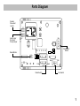
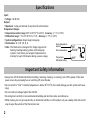
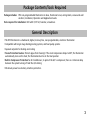
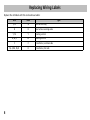
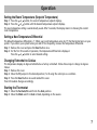
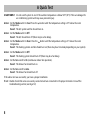
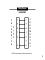
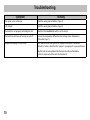
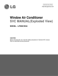
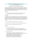
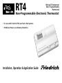
RT4
Manual Changeover
Non-Programmable
Hardwired
Non-Programmable Electronic Thermostat
• For use with Friedrich PTAC and Vert-I-Pak Systems
• 30-Minute Power Loss Memory Retention
Installation, Operation & Application Guide
Table of Contents
Parts Diagram........................................................................................................................................... 1
Specifications ........................................................................................................................................... 2
Important Safety Information .................................................................................................................. 2
Package Contents/Tools Required ............................................................................................................. 3
General Description .................................................................................................................................. 3
To Remove Existing Thermostat ................................................................................................................ 4
To Install Thermostat ................................................................................................................................ 4
Replacing Wiring Labels ........................................................................................................................... 6
Operation ................................................................................................................................................. 7
A Quick Test.............................................................................................................................................. 8
Wiring Diagrams ...................................................................................................................................... 9
Troubleshooting ..................................................................................................................................... 10
caution!: This thermostat should be installed by trained technicians only. Adhere to all local and
national codes. Disconnect all power to the system before installing, removing, or cleaning.
Parts Diagram
Celsius/
Fahrenheit
Jumper
Heat Pump/
Non-Heat
Pump Jumper
F–C
NON–HP
HP
Gas
Electric
Reset Button
Auto
Cool
Mode Switch
Off
Gas/Electric
Switch
On
Heat
Fan Switch
1
Specifications
Input:
• Voltage: 18-30 VAC
Output:
• Maximum: 1 amp per terminal (3 amp total for all terminals)
Temperature Ranges:
• Temperature control range: 45°F to 90°F (7°C to 32°C) Accuracy: ± 1°F (± 0.5°C)
• Differential range: 1°F to 3°F (0.5°C to 1.5°C) Accuracy: ± 1°F (± 0.5°C)
• System configurations: Single stage heat pump
• Terminations: R, C, W, Y, B, O, G
Room temperature
setpoint
• Note: This thermostat is designed for: Single stage electric
heating, heating/cooling systems and heat pump
Room temperature
systems. It will retain your setpoint temperatures in
memory for up to 30 minutes during a power outage.
Temperature
differential setting
SET
ROOM
DIFF
Important Safety Information
• Always turn off the thermostat before installing, removing, cleaning, or servicing; turn off the power at the main
power source by unscrewing fuse or switching off circuit breaker
• Do not switch to “Cool” if outside temperature is below 50°F (10°C), this could damage your A/C system and cause
injury
• Do not install on voltages higher than 30 VAC
• All wiring must conform to local and national building and electrical codes and ordinances
• While cleaning, do not get soap directly on thermostat switches or LCD readout; only use a damp cloth with a mild
soap to wipe the outside of the thermostat cover
2
Package Contents/Tools Required
Package includes: RT4 non-programmable thermostat on base, thermostat cover, wiring labels, screws and wall
anchors, Installation, Operation and Application Guide.
Tools required for installation: Drill with 3/16” bit, hammer, screwdriver.
General Description
• The RT4 thermostat is a hardwired, digital, mercury-free, non-programmable, electronic thermostat
• Compatible with single stage heating/cooling systems, and heat pump systems
• Separate setpoints for heating and cooling
• Freeze Protection Feature: Protects pipes from freezing! If the room temperature drops to 40°F, the thermostat
automatically turns on the heat; the thermostat must be in the Heat position
• Built-in Compressor Protection for Air Conditioners; to protect the A/C’s compressor, there is a 5-minute delay
between the system turning off and the A/C starting
• 30-minute power loss memory retention protection
3
To Remove Existing Thermostat
ELECTRICAL SHOCK HAZARD – Turn off power at the main service panel by removing the fuse
or switching the appropriate circuit breaker to the OFF position before removing the existing
thermostat.
1. Turn off power to the heating and cooling system by removing the fuse or switching off the appropriate circuit
breaker.
2. Remove cover of old thermostat. This should expose the wires.
3. Label the existing wires with the enclosed wire labels before removing wires. See table on Page 6 for old and
new label identification.
4. After labeling wires, remove wires from wire terminals.
5. Remove existing thermostat base from wall.
6. Refer to the following section for instructions on how to install this thermostat.
To Install Thermostat
ELECTRICAL SHOCK HAZARD – Turn off power at the main service panel by removing the fuse
or switching the appropriate circuit breaker to the OFF position before removing the existing
thermostat.
IMPORTANT: Thermostat installation must conform to local and national building and electrical codes and
ordinances.
Note: Mount the thermostat about five feet above the floor. Do not mount the thermostat on an outside
wall, in direct sunlight, behind a door, or in an area affected by a vent or duct.
1. Turn off power to your system. Move the Mode switch to Off.
2. Move the Fan switch to Auto.
3. To remove cover, insert and twist a coin or screwdriver in the slots on the sides of the thermostat.
4
To Install Thermostat (continued)
4.
5.
6.
7.
8.
9.
10.
11.
12.
13.
14.
15.
16.
Put thermostat base against the wall where you plan to mount it (Be sure wires will feed through the wire
opening in the base of the thermostat).
Mark the placement of the mounting holes.
Set thermostat base and cover away from working area.
Using a 3/16” drill bit, drill holes in the places you have marked for mounting.
Use a hammer to tap supplied anchors into mounting holes.
Align thermostat base with mounting holes and feed the control wires through wire opening.
Use supplied screws to mount thermostat base to wall.
caution!: Be sure exposed portion of wires does not touch other wires.
Tighten screws on terminal block. Gently tug wire to be sure of proper connection. Double check that each wire
is connected to the proper terminal.
Seal hole for wires behind thermostat with non-flammable insulation or putty.
Set the Gas/Electric switch to electric, and heat pump jumper to NON-HP.
Set the temperature scale jumper to Fahrenheit or Celsius.
Replace cover on thermostat by snapping it in place.
Turn on power to the system at the main service panel.
5
Replacing Wiring Labels
Replace the old labels with the enclosed new labels:
6
Old
New
F, G
G
Type
Fan control relay
B
B
Heat active reversing valve
Y, Y6
Y
Cooling control
H, W, 4
W
Heating control
C
C
Transformer, common side
M, 4, RH, RS, R
R
Transformer, hot side
Operation
Setting the Room Temperature (Setpoint Temperature)
Step 1: Press the
or
button; the current temperature setpoint displays.
Step 2: Press the
or
button until the desired temperature setpoint displays.
The new temperature setting is automatically saved. After 5 seconds, the display returns to showing the current
room temperature.
Setting a New Temperature Differential
The default temperature differential is 1°. When your room temperature varies by 1°F, the thermostat turns on your
system. If you notice your system turning on and off too frequently, increase the temperature differential.
Step 1: Remove the cover and press the Reset button once.
Step 2: For the first 10 seconds of operation, the temperature differential is displayed.
Press the
or
button to select desired setting.
Changing Fahrenheit to Celsius
The temperature displays in degrees Fahrenheit as a factory set default. Follow these steps to change to degrees
Celsius:
Step 1: Remove the cover.
Step 2: Move the F/C jumper to the desired position, F or C using the center pin as a common.
Step 3: Press the Reset button once and reinstall the cover.
Your LCD readout changes accordingly.
Starting the Thermostat
Step 1: Move the Fan Auto/On switch into the Auto position.
Step 2: Move the Mode switch to Heat or Cool, depending on the season.
7
A Quick Test
caution!: Do not switch system to cool if the outdoor temperature is below 50°F (10°C). This can damage the
air conditioning system and may cause personal injury.
Action: Set the Mode switch to Cool. Press the
button until the temperature setting is 3°F below the room
temperature.
Result: The A/C system and fan should turn on.
Action: Set the Mode switch to Off.
Result: The A/C should turn off (there may be a fan delay).
Action: Set the Mode switch to Heat. Press the
button until the temperature setting is 3°F above the room
temperature.
Result: The heating systems and fan should turn on (there may be a time delay depending on your system).
Action: Set the Mode switch to Off.
Result: The heating system should turn off (there may be a fan delay).
Action: Set the Fan switch to On (continuous indoor fan operation).
Result: The blower fan should turn on.
Action: Set the Fan switch to Auto.
Result: The blower fan should turn off.
If the above test was successful, you have a proper installation.
If not: Double check that wires are securely connected and are connected to the proper terminals. Consult the
troubleshooting section (see Page 10).
8
Wiring Diagram
HARDWIRED
F
R
I
E
D
R
I
C
H
P
T
A
C
C
C
R
R
W
W
Y
Y
B
B
O
G
G
T
H
E
R
M
O
S
T
A
T
NOTE: B terminal used on heat pump models only
9
Troubleshooting
Symptom
The system is not turning on
Remedy
Check the wiring (see Installation, Page 4)
LCD is blank
Check the wiring (see Installation, Page 4)
Thermostat is not properly controlling the fan
Check that the Gas/Electric switch is set to electric
Thermostat is continuously turning on and off
Increase the temperature differential (see Setting a New Temperature
Differential, Page 7)
Temperature display is not accurate
Your thermostat has two options for temperature readout: Fahrenheit
(default) or Celsius; check that the “jumper” is properly set to your preference
Plug the hole for wiring behind the thermostat with non-flammable
insulation to prevent airflow into the thermostat
10
Friedrich Air Conditioning Co.
Post Office Box 1540 • San Antonio, Texas 78295-1540
4200 N. Pan Am Expressway • San Antonio, Texas 78218-5212
(210) 357-4400 • FAX (210) 357-4480
www.friedrich.com