1
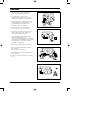
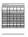
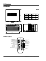
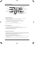
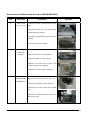
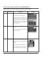
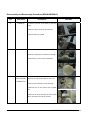
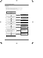
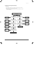
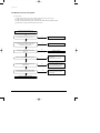
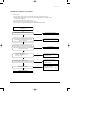
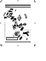
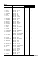
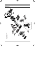
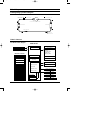
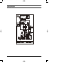
DB98_04511A(2)-CO
2/18/03 4:08 PM
Page 3
ROOM AIR CONDITIONER
SERVICE
AIR CONDITIONER
SP06A10
SP08A10
SP10A10
SP12A10
Manual
CONTENTS
11. Precautions
12. Product Specifications
13. Installation and Operating
Instructions
14. Disassembly and Reassembly
15. Troubleshooting
16. Exploded Views and Parts List
17. Block Diagram
18. PCB Diagram
19. Wiring Diagram
10. Schematic Diagram
DB98_04511A(2)-1
2/18/03 4:09 PM
Page 1-1
1. Precautions
1. Warning: Prior to repair, disconnect the
power cord from the circuit breaker.
2. Use proper parts: Use only exact
replacement parts. (Also, we recommend
replacing parts rather than repairing them.)
3. Use the proper tools: Use the proper tools
and test equipment, and know how to use
equipment may cause problems laterintermittent contact, for example.
4. Power Cord: Prior to repair, check the
power cord and replace it if necessary.
Fig. 1-1 Avoid Dangerous Contact
5. Avoid using an extension cord, and avoid
tapping into a power cord. This practice
may result in malfunction or fire.
6. After completing repairs and reassembly,
check the insulation resistance.
Procedure: Prior to applying power, measure
the resistance between the power cord and the
ground terminal. The resistance must be
greater than 30 megaohms.
7. Make sure that the grounds are adequate.
Fig. 1-2 No Tapping and No Extension Cords
8. Make sure that the installation conditions
are satisfactory.
Relocate the unit if necessary.
9. Keep children away from the unit while it is
being repaired.
10. Be sure to clean the unit and its surrounding
area.
Fig. 1-3 No Kids Nearby!
Fig. 1-4 Clean the Unit
FRIEDRICH AIR CONDITIONING CO.
1-1
2.Product Specifications
2-1 Table
Item
Unit of
SP06A10
Measure
SP08A10
Type
Dimension:
(Width×Height×Depth)
SP10A10
SP12A10
WINDOW
mm
520×345×485
600×394×595
Voltage
Volt
115
Phase
-
SINGLE
Frequency
Hz
60
Operation Current
A
5.4
6.6
9.3
10.5
Power Consumption
W
610
740
1000
1170
Refrigerant Type
Refrigerant Change
FREON
R22
g
300
470
450
635
BTU/h
6500
8000
10800
12600
BTU/h.W
10.8
10.8
10.8
10.8
Net Weight
Kg
26
29
43
45
Condenser
Row
2×15
3×15
2×17
3×17
Condenser Fan
Type
Evaporator
Row
Evaporator Fan
Type
Capacity
EER
Propeller Fan
2×11
2×11
2×12
2×10
Blower
Fan Motor
MODEL
YSLA-40-6-0002
YSLA-40-6-0003
YGN60-6B
YGN60-6B
Compressor(Rotary)
MODEL
39A062HS1EA
44A076HU1EB
44B098HX1EF
44B117HX1EL
MRA12146-120
MRA12083-120
08
08
MRA12132-12007
MRA12053-12007
Overload Protect
-
Compressor Capacitor
μF/VAC
40/370
35/370
45/370
50/370
Fan Motor Capacitor
μF/VAC
8/450
8/450
15/250
15/250
RPM
920/850/800
1050/1010/970
890/850/800
890/860/750
Fan Speed
Thermo Control
-
FRIEDRICH AIR CONDITIONING CO.
THERMISTOR
2-1
DB98_04511A(2)-1
2/18/03 4:09 PM
Page 2-4
MEMO
2-3
FRIEDRICH AIR CONDITIONING CO.
2-2 Dimensions
2-2-1 Main Unit
(Unit : mm)
D
MODEL
W
H
D
520
345
485
600
394
595
SP06A10
SP08A10
SP10A10
SP12A10
Front view
H
H
Side view
W
2-2-2 Remote Control
Remote control
transmission indicator
Operating mode
(
Cool,
Dry,
Mode selection button
(Cool, Fan, Dry)
Fan)
Temperature setting
Sleep mode
Temperature adjustment
buttons
Sleep timer setting button
Energy Saving mode
Fan speed adjustment
button
Fan speed
On Timer setting
Off Timer setting
Energy Saving button
Timer setting button
Timer Set/Cancel button
Battery discharge indicator
On/Off button
2-4
FRIEDRICH AIR CONDITIONING CO.
DB98_04511A(2)-1
2/18/03 4:09 PM
Page 3-1
3. Installation and Operating Instructions
3-1 Installation
3-1-1 Selecting Area for Installation
1. Make sure that you install the unit in an area
providing good ventilation. The air conditioner
must not be blocked by any obstacle affecting the
air flow near the air inlet and air outlet.
2.
Make sure that you install the unit in an area that
allow good air handling. The installation area
must be able to endure vibration from the unit.
3.
Make sure that you install the unit away from
heat or vapor.
4.
Make sure that you install the unit in an area
which is cool and has adequate space.
5.
Make sure that you install the unit in an area
away from TVs, audio units, cordless phones,
fluorescent lighting fixtures and other electrical
appliances (obtain a clearance of at least one
meter).
6.
Make sure that you install the unit in an area
which provides easy drainage for condensed
water.
7.
Make sure that you install the unit in an area not
exposed to rain or direct sunlight.
(Install a separate sunblind if exposed to direct
sunlight.)
8.
Make sure that you install the unit in an area
allowing good air movement. Do not install it in
a space that would cause noise amplification of
noise.
9. Fix the unit firmly if mounted in a high place.
Caution:
Do not use the air conditioner in the following environments : greasy areas (including areas near
machines), or marine areas. Contact your local dealer for advice.
FRIEDRICH AIR CONDITIONING CO.
3-1
DB98_04511A(2)-1
2/18/03 4:09 PM
Page 3-2
3-2 Function Description
Timer indicator
Temperature/Timer
settings
Energy Saver indicator
Remote control
sensor
Dry adjustment indicator
Fan speed
adjustment button
On/Off button
Mode selection button
(Cool, Fan, Dry)
Temperature
adjustment buttons
3-2-1 Cooling operation mode
The compressor is turned on and off according to the ambient temperature and set temperature.
1) Compressor on and off control
• Compressor on and off control according to the ambient temperature
* The compressor is turned off when "ambient temperature = set temperature
* The compressor is turned on when "ambient temperature = set temperature +1˚C"
2) Default value after power reset ➔ set temperature = 75˚F
Fan speed = High
3) Set temperature indicating (setting) range : 1˚F interval from 64˚F to 86˚F.
3-2-2 Fan operation mode
1) If "Fan operation mode" signal is received from remocon or panel.
➔ the compressor is immediately turned off and only fan motor is operated at set blowing speed.
➔ it changes such as "High ➔ Med ➔ Low ➔ High"( if Fan speed is selected).
2) The initial Fan motor speed is set to "High".
3) The set temperature can not be indicated and set.
3-2-3 Energy saver operation mode
* If the compressor turn off at the cooling operation, the fan motor turn off after operation during the fixation
time only, and operation that energy saver by turn off the fixation time only, and operation that energy saver
by turn off the motor continuously before the condition of the compressor on.
* The fan motor is not operated at flow wind operation.
* Energy saver operation specification at the cooling operation.
1) Fan motor control in compressor on : operate with setting wind speed
2) Fan motor control in compressor off : After compressor off, the fan motor is operated breeze for 2 minutes
and then it turn off.
3) After the fan motor off, the compressor and fan motor is operated normally when the compressor on.
3-2
FRIEDRICH AIR CONDITIONING CO.
DB98_04511A(2)-1
2/18/03 4:09 PM
Page 1
Installation and Operating Instructions
3-2-4 Sleep operation mode
1) Enable to sleep operation only when cooling operation.
2) First, 7-SEG LED DISPLAY "SLEEP" while 15 second, Second, 7-SEG LED DISPLAY "8Hr"
And, automatically SET OFF after operated while 8 Hour
3) If sleep operation, setting Temperature rise 1˚C after 1 Hour
4) ON TIMER operation, not operation, ENERGY SAVER operation, not sleep operation.
3-2-5 Dry operation mode
If the atmosphere in the room is very humid or damp,use this operation mode. It can remove excess humidity
without lowering the room temperature too much.
1) The quantity of air is adjusted automatically.
3-2-6 LED display indication in case of error detection
ERROR OPERATION
7-SEG
LED DISPLAY
ROOM THERMISTOR
(OPEN or SHORT)
E1 displayed
1) Set operation in case of error occurrence.
• Malfunction of each temperature sensor (open, short)
- Error mode display, warning sound.
- The operation status is off.
FRIEDRICH AIR CONDITIONING CO.
3-3
DB98_04511A(2)-1
2/18/03 4:09 PM
Page 2
MEMO
3-4
FRIEDRICH AIR CONDITIONING CO.
DB98_04511A(2)-1
2/18/03 4:09 PM
Page 3
4. Disassembly and Reassembly
4-1 Compressor Replacement Flow Chart
Locate cause of defect
Release refrigerant
Disconnect electrical wiring
from compressor
Cut refrigerant lines
from compressor
Plug disconnected lines
Replace compressor
Inspect electrical
wiring for defects,
and terminals for
correct and secure
connections
Solder discharge line
Solder suction line
Use nitrogen gas
Perform soldering function
Y
Problem?
Fill system with
nitrogen gas
N
Check for leakage
Corrective action
Leakage?
Y
Check refrigerant oil level
N
Release nitrogen gas?
Y
Low oil level?
N
Evacuate system
Add oil as necessary
Recharge system
Pinch and braze filling tube
FRIEDRICH AIR CONDITIONING CO.
4-1
DB98_04511A(2)-1
2/18/03 4:09 PM
Page 4
4-2 Checking the oil
Fill the transparent container with 10cc of oil, and then conduct the test.
4-2-1 Oil quality
Oil Condition
Condition of
Refrigerant Cycle
Color
Odor
Normal
Straw Yellow
No Odor
Return with the system
Over-heated
Brown Color
-
Change the oil
Compressor Damage
Dark Brown
Pungent oil
Change the oil
Remarks
4-2-2 Replacing and refilling the refrigerant oil
1. Change the compressor - DO NOT recharge the oil as the compressor itself is
already charged.
2. Change the condenser .... add 50cc
3. Change the evaporator .... add 50cc
4. When the refrigerant is replaced .... add 30cc oil.
5. After vacuum is completed, the oil is filled through the high pressure side.
6. In the event of a refrigerant leak, generally it is not necessary to add oil.
(Unless the oil has leaked significantly.)
4-2
FRIEDRICH AIR CONDITIONING CO.
4-3.Disassembly and Reassembly Procedure(SP10A10/SP12A10)
Stop operating the air conditioner, and pull out the power cord before repair.
No.
Part Name
Procedures
Remarks
1
Ass’y Grille
1.Pull the Grille air inlet and Guard air filter out.
2.Remove the screw on the panel front.
3.Hold the lower part of panel with two hands
while pressing down on both sides of the lower
part of the cabinet, pull it forward by about
30mm,and
then
lift
it
up
carefully
for
removal.(Must un-connect the Displayer with
the controller inside.)
2
Ass’y Cabinet
1.Remove 2 screws on the both side of the
cabinet.
2.Pull the front part both side, and remove the
unit from the cabinet.
3
Ass’y Control
1.Remove the earth screw fixed on the cabinet.
2.Remove 3 screws fixed on the partition and
frame up.
3.Remove the screw fixed for the power cord.
4.Un-connect the motor wire and comp lead
wire, then take out the control box upward.
FRIEDRICH AIR CONDITIONING CO.
4-3
Disassembly and Reassembly Procedure(SP10A10/SP12A10)
No.
Part Name
Procedures
Remarks
4
Plate reinf&
Case evap up
1..Remove 4 screws on the partition and case
cond.
2.Remove the plate reinf. (The shape maybe
different depend on models)
3.Remove the seal sticked on the case evap up
carefully.
4.Pull the case evap up upward.
5
Plate evap
casing &
Blower
1.Remove the cover on the evaporator.
2.Remove all screws on the evaporator.
3.Pull the evaporator forward carefully.
4.Remove all screws fixed on plate evap
casing, then pull it out completely.
3.Remove the nut and remove the Blower.
6
Case Cond &
Fan Propeller
& Motor Fan
1.Remove 2 screws on the rear side of the
base pan, and all screws fixed on case cond.
2.Pull up the condenser from the base pan.
3.Remove the nut and remove the Propeller
fan.
4.Remove 4 screw(fixed on the mounter ), then
take out the motor.
4-4
FRIEDRICH AIR CONDITIONING CO.
4-5.Disassembly and Reassembly Procedure(SP06A10/SP08A10)
Stop operating the air conditioner, and pull out the power cord before repair.
No.
Part Name
Procedures
Remarks
1
Ass’y Grille
1.Pull the Grille air inlet and Guard air filter out.
2.Remove the screw on the panel front.
3.Hold the lower part of panel with two hands
while pressing down on both sides of the lower
part of the cabinet, pull it forward by about
30mm,and
then
lift
it
up
carefully
for
removal.(Must un-connect the Displayer with
the controller inside.)
2
Ass’y Cabinet
1.Remove 2 screws on the both side of the
cabinet.
2.Pull the front part both side, and remove the
unit from the cabinet.
3
Ass’y Control
1.Remove the earth screw fixed on the cabinet.
2.Remove 3 screws fixed on the partition and
frame up.
3.Remove the screw fixed for the power cord.
4.Un-connect the motor wire and comp lead
wire, then take out the control box upward.
FRIEDRICH AIR CONDITIONING CO.
4-5
Disassembly and Reassembly Procedure(SP06A10/SP08A10)
No.
Part Name
Procedures
Remarks
4
Frame up
1..Remove 2 screws on the frame up and case
cond.
2.Remove all the screws on the frame up.
3.Pull the frame up upward.
5
Blower
1.Remove 3 screws on the evaporator.
2.Pull the evaporator from frame low carefully.
3.Remove the nut and remove the Blower.
6
Case Cond &
Fan Propeller
& Motor Fan
1.Remove 2 screws on the rear side of the
base pan, and all screws fixed on case cond.
2.Pull up the condenser from the base pan.
3.Remove the nut and remove the Propeller
fan.
4.Remove the earth screw(fix the motor earth
wire), then take out the motor upward.
4-6
FRIEDRICH AIR CONDITIONING CO.
DB98_04511A(2)-2
2/18/03 4:12 PM
Page 5-1
5. Troubleshooting
Check the basic checkpoints first to determine whether it is machine trouble or a problem
in the operation method. When it is not related to the basic checkpoints, perform checking
in accordance with the procedures of troubleshooting by symptom.
5-1 Basic Checkpoints for Troubleshooting
1) Is the voltage of the power source appropriate ?
(1) It should be within the rating voltage ±10% range.
(2) The air conditioner may not operate properly when the voltage is out of this range.
2) Is the connection with the fan motor, compressor wire, and starting condenser
appropriately made ?
3) The symptoms listed in the table below are not indicative of machine trouble.
Symptom
Cause and check
No operation
• Check whether there is power failure or the power plug is pulled out.
• Check whether the unit is stopped as a result of completion
of the sleep time.
• Pull out the power plug for ten seconds, and then insert it again.
Air flows, but
no cooling
• Check whether the Air filter is clogged with dust or is dirty.
• Check whether the desired temperature is too high. Set the desired
temperature to a lower level than the current temperature.
• Check whether it is in "FAN" mode.
The remocon does
not operate
• Check whether battery is completely depleted.
• Check whether the battery is properly inserted.
• Check whether the receiving window of the remocon for the assembly
main PCB is blinded.
• Check whether the remocon is affected by jamming due to a neon sign.
No temperature
setting
• Check whether the unit is in "FAN" mode.
(In "FAN" mode, only the current temperature is displayed, and the
desired temperature is not set.)
❈ Checking and Display of Fault Area
ERROR OPERATION
ERROR OPERATION
ROOM THERMISTOR (OPEN OR SHORT)
E1 displayed
FRIEDRICH AIR CONDITIONING CO.
5-1
DB98_04511A(2)-2
2/18/03 4:12 PM
Page 5-2
5-2 Troubleshooting by Symptom
5-2-1 No power
1) Check points
(1) Is the voltage of the power source normal ? (the rating voltage ±10% range.)
(2) Is the electric wire in good contact ?(CN 71, RY 71)
(3) Is the output voltage of the IC01(KA 7812) normal ?(DC 11.5V ~ DC 12.5V)
(4) Is the output voltage of the IC02(KA 7805) normal ?(DC 4.5V ~ DC 5.5V)
Turn off the power, and then turn it on again five
seconds later.
Y
Dose the buzzer sound, when the power on?
Normal operation.
N
Check whether the "COOLING ICON" LED lamp is
on, and the operation starts when pressing the
ON/OFF button of the remocon.
Y
Normal operation.
N
Y
Is the F701(3.15A) fuse blown?
Replace the fuse.
N
Is the primary voltage of the transformer normal?
(the rating voltage ±10% range.)
N
Check the power cord and electric wire.
Y
Is the secondary voltage of the transformer normal?
(AC 13V ~ AC 17V)
N
Check and replace the trans.
Y
N
Is the rectifier diode bridge(BD61) normal?
Y
- Is the voltage of DC 17V ~ DC 23V applied at both
ends of the C101 electrolytic condenser?
- Is the voltage of DC 12V applied at both ends of
the C102 electrolytic condenser?
- Is the voltage of DC 5V applied at both ends of
the C103 electrolytic condenser?
N
• Check the BD61 for cold
soldering.
• Replace the rectifier diode
• Check both ends of the C101 for
short and cold soldering.
• Check the +12V for a short.
• Check the +5V for a short.
• Check and replace the C101~104.
Y
N
Are the IC01(KA7812) or IC02(KA7805) normal?
Y
• Check the IC01 or IC02 for cold
soldering and a short.
• Replace the IC01 or IC02.
Replace the assembly main PCB.
5-2
FRIEDRICH AIR CONDITIONING CO.
DB98_04511A(2)-2
2/18/03 4:12 PM
Page 5-3
Troubleshooting
5-2-2 When the Touch Key pad and Led Display
1) Check points
(1) Is the voltage of the power source normal ? (the rating voltage ±10% range.)
(2) Is the electric wire in good contact ?(CN71, RY71)
(3) Is the connection of the assembly main PCB, and TOUCH KEY PAD in good
contact? (SW01-SW05)
Turn off the power, and then turn it on again
five seconds later.
N
Normal operation
When the LED display is
not operated.
Y
Check the micom
(IC05) for a short,
and replace it.
N
Is the voltage of the micom
(IC05) No.1, 2, 38~43 port a
square wave?
Y
Check the micom
(IC05) for a short,
and replace it.
N
Is the voltage of the micom
(IC05) No.3, 4, 10, 11, 44 port
a square wave?
Y
Check the Q901~
Q905 for a short,
and replace it.
N
Is the voltage of the
Q901 ~ Q905 square wave?
When the membrane key is
not operated.
N
Normal operation
Y
Is the voltage of the
micom (IC05) No.13, 14 port
a square wave?
N
Check the micom
(IC05) for a short,
and replace it.
N
Check the micom
(IC05) for a short,
and replace it.
Y
Is the voltage of the micom
(IC05) No.3, 4, 10, 11, 44
port a square wave?
Y
Replace the membrane
key pad.
Y
Check the IC06
for a short, and
replace it.
N
Is the voltage of the
IC06 No. 10~16 a square
value?
Y
Replace the membrane key pad
FRIEDRICH AIR CONDITIONING CO.
5-3
DB98_04511A(2)-2
2/18/03 4:12 PM
Page 5-4
Troubleshooting
5-2-3 When the remocon is not operated
1) Check points
(1) Is the voltage of the power source normal ? (the rating voltage ±10% range. )
(2) Is the electric wire in good contact ? (CN71, RY71)
(3) Is the assembly main PCB in good contact with the TOUCH KEY PAD(SW01-SW05)
(4) Is the battery voltage of the remocon above DC 2.7V?
Turn off the power, and then turn it on
again five seconds later.
N
Go to the clause "No power".
Dose the Buzzer sound, when the power on?
Y
Check whether the "COOLING ICON" LED lamp is on
and th operation starts when pressing the
on/off button of the remocon.
Y
The remocon is normally operated.
N
Is the battery voltage of the remocon above
DC 2.7V?
N
Replace the battery.
Y
N
• Check the X-TAL for cold soldering
and a short.
• Replace relevant components.
N
• Check the micom(ICT1) Q1, and
Q2 for cold soldering and a short.
• Replace relevant components.
Does the X-TAL(RJ 455JB) oscillate normally?
Y
Is the collector voltage of the remocon Q1, Q2
a square wave?
Y
Is the input voltage of the micom(IC05) No.15
pin of the assembly main PCB a aquare wave?
N
• Check the R415 components.
• Check the assembly main PCB
micom(IC05).
Y
Replace the assembly main PCB.
5-4
FRIEDRICH AIR CONDITIONING CO.
DB98_04511A(2)-2
2/18/03 4:12 PM
Page 5-5
Troubleshooting
5-2-4 When the compressor is not operated
1) Check points
(1) Is the voltage of the power source normal ? (the rating voltage ±10% range. )
(2) Is the desired temperature lower than the indoor temperature in the “COOL” mode?
(Compressor stopped)
(3) Is the starting condenser in good contact?
(4) Is the electric wire in good contact ? (CN71, RY71)
(5) Is the output voltage of the IC01(KA7812) and IC02(KA7805) normal ?
Turn off the power, and then turn it on again five
seconds later.
N
Go to the clause "No power".
Dose the Buzzer sound, when the power on?
Y
Check whether the "COOLING ICON" LED lamp is on
and the operation starts when pressing the on/off
button of the remocon.
N
• Go to the clause "when he remocon
does not operate".
Y
Check whether the compressor is activated in three
minutes after turning on the power with the "CoolING
ICON" LED lamp being switched on when selecting the
cool mode of the remocon.
Y
Normal operation.
N
Is the IC03 output normal?
- When the compressor is on, IC03
No. 13 pin → Low.
N
• Check the IC03 for short and cold
soldering.
• Replace the IC03.
N
• Check the relay coil resistance.
(resistance : About 150Ω±20Ω)
• Replace the relay.
Y
Does the relay(RY71) operate normally?
- When the compressor is ON, the RY71 should operate.
Y
N
Is the compressor normal?
Y
• Check the operation of the O.L.P,
and replace it if necessary.
• Check the compressor
resistance.(0Ω : short, ∞Ω : open)
Replace the compressor.
FRIEDRICH AIR CONDITIONING CO.
5-5
DB98_04511A(2)-2
2/18/03 4:12 PM
Page 5-7
Troubleshooting
5-2-5 When the fan motor does not operated
1) Check points
(1) Is the voltage of the power source normal ? (the rating voltage ±10% range. )
(2) Is the electric wire in good contact ?(CN71, RY71)
(3) Is the starting condenser(FAN MOTOR) in good contact?
(4) Is the fan motor connector in good contact?(CN73)
(5) Is the output voltage of the IC01(KA7812) and IC02(KA7805) normal ?
Turn off the power, and then turn it on again five
seconds later.
N
Go to the clause "No power".
Dose the buzzer sound, when the power on?
Y
Check whether the "COOLING ICON" LED lamp is on
and the operation starts when pressing the
on/off button of the remocon.
N
• Go to the clause of "when the
remocon does not operated".
Y
Is the IC03 output normal?
- When the fan motor is High, IC03 No. 12 pin → Low.
- When the fan motor is Med, IC03 NO. 14 pin → LOW.
- When the fan motor is Low, IC03 No. 15 pin →Low.
N
• Check the IC03 for a short and cold
soldering.
• Replace the IC03.
N
• Check the relay coil resistance.
(Normal: About 400Ω)
• Replace the relay.
Y
Does the relay(RY 72, 73,74) operate normally?
- When the fan motor is High, RY74 should operate.
- When the fan motor is Med, RY73 should operate.
- When the fan motor is Low, RY72 should operate.
Y
Is the fan motor normal?
N
• Check the fan motor resistance.
(0Ω : short, ∞Ω : open)
• Check the fan motor thermal fuse?
Y
Replace the fan motor.
FRIEDRICH AIR CONDITIONING CO.
5-7
DB98_04511A(2)-2
2/18/03 4:12 PM
Page 6-1
6. Exploded View and Parts List
8
26
27
29
33
28
22
24
23
21
25
7
5
4
6
30
10
30-7
2
30-11
30-10
30-8
30-5
30-1
30-4
30-3
30-2
1-1
1-3
3
30-6
11
1-2
1-5
1-4
1
EXPLODED VIEW(SP06A10/SP08A10)
13
9
15
12-2
12-3
17
16
12-1
19
12-6
12-5
14
12-4
20
34
18
6-1 Main unit
You can search for the updated part code
number through the ITSELF.
35
URL : http://itself.sec.samsung.co.kr
FRIEDRICH AIR CONDITIONING CO.
6-1
Exploded View and Parts List
■Part List
No
1
Description
Code No.
Specification
Q'TY
SP06A10
SP08A10
ASSY PANEL FRONT
DB92-00398B
ASSY,HIPS
1
1
1-1
PANEL FRONT
DB64-00566A
HIPS,-,W343
1
1
1-2
GRILLE AIR INLET
DB64-00567B
SEA,HIPS
1
1
1-3
BLADE V
DB66-00349A
HIPS,T2.5
4
4
1-4
LINK BLADE
DB66-00165A
PE,L97.5,T1.3
2
2
1-5
FRAME BLADE
DB61-01009A
HIPS
1
1
2
FILTER
DB63-00513A
HIPS,-,W212
1
1
3
EVAPORATOR
DB96-01028A
2R×11S,FP1.2
1
1
4
ASSY FRAME LOW
DB90-00328A
ASSY
1
1
5
NUT-FRANGE
DB60-30004A
2C M6 SM20C NTR
1
1
6
BLOWER
DB67-00099A
ABS
1
1
7
MOTER FAN
DB31-00149B
80/75/70
1
-
DB31-00149A
1.12/1.05/0.99
-
1
1
8
FAN-PROPELLER
DB67-50077A
ABS
1
9
NUT-FRANGE
DB60-30020A
M6,LEFT
1
1
10
LEVER DAMPER
DB66-00430A
SC-97471R
1
1
11
ASSY FRAME UP
DB90-00293A
ASSY
1
1
12
ASSY PANEL CONTROL
DB92-00395A
ASSY
1
1
12-1 COVER PANEL CONTROL
DB63-00514A
ABS(V5)
1
1
12-2 PANEL DISPLAY
DB64-00565A
ABS(V5)
1
1
12-3 PANEL BUTTON
DB64-00564A
ABS,-,W18,L90
1
1
12-4 COVER MODULE
DB63-00512A
PC,T1,W23
1
1
12-5 ASSY PCB PANEL
DB93-01493A
SEA-PJT,RAC PANEL
1
1
12-6 THERMISTOR
DB32-10051D
10K/25,-,3425K
1
1
13
CASE COND
DB90-00337A
PP
1
1
14
ASSY BASE
DB90-20212F
SGCC-M,SC94445T
1
1
15
ASSY COND
DB96-00995A
2R×15S,FP1.5
1
-
DB96-01027A
3R×15S,FP1.5
-
1
1
16
ASSY CABINET
DB90-00133P
ASSY
1
17
ASSY SHUTTER-LF
DB92-00113A
SPS-P/J,ASSY
1
1
18
ASSY SHUTTER-RH
DB92-00112A
SPS-P/J,ASSY
1
1
19
SHUTTER-ANGLE UP
DB64-00048B
ASV08FAS2,HIPS,T3.0
1
1
20
BRACKET-INSTALL
DB61-30219F
SGCC-A
2
2
21
NUT-TERMINAL COVER
DB60-30001A
M5,-,SM20C
1
1
22
COMPRESSOR
39A062HS1EA
6200BTU,115V
1
-
44A076HU1EB
115V 1PHASE 60HZ 7600
-
1
1
23
COVER-TERMINAL
DB63-10026A
GE,-,NORYL,-,SEI-701
1
24
O.L.P
DB35-00006G
MRA12146-12008
1
-
DB47-20066B
MRA12083-12008
-
1
25
GASKET
DB63-20003A
EPDM,T0.8
1
1
26
NUT WASHER
DB60-30028A
M8,ZPC
3
3
27
GROMMET-ISOLATOR
DB73-00016A
EPDM,-,BLK,OK-PJT
3
3
28
TUBE SUCTION
DB62-01374A
C1220T-0
1
-
DB62-00484A
C1220T-0
-
1
DB62-00675A
OD7.93
1
-
DB62-00483A
C1220T-0
-
1
DB93-01633A
TOP,ELEC
1
-
DB93-01633B
TOP,ELEC
-
1
29
30
TUBE DISCHARGE
ASSY CONTROL BOX
30-1 CASE CONTROL-LOW
DB61-00669A
SGCC-M,T0.7
1
1
30-2 CASE CONTROL-UP
DB61-00670A
SGCC-M,T0.7
1
1
30-3 BRACKET-CONTROL
DB61-00676A
SGCC-M,T0.7
1
1
30-4 TRANSFORMER
DB26-00006G
AC115V,50/60HZ,DC17V
1
1
30-5 C-FILM
2301-001448
8µF,450VAC
1
1
30-6 POWER CORD
DB39-00343D
125V,13A
1
1
30-7 C-OIL
2501-001229
40µF,370VAC
1
-
2501-001228
35µF,370VAC
-
1
1
30-8 CLIP CAPACITOR
DB65-00031A
SGCC-M,T0.7
1
30-10 ASSY MIAN PCB
DB93-01492A
SEA-PJT
1
1
30-11 PANEL BONTROL
DB63-00511A
ABS(V5),-,W140,L98
1
1
DB62-01316A
ID1.3×L600
1
-
DB62-01288A
ID1.42×L900
-
1
33
TUBE CAPILLARY
34
ASSY-SCREW
DB97-30156C
ASSY
1
1
35
ASSY REMOCON
DB93-01364X
AS-K410/K610
1
1
6-2
FRIEDRICH AIR CONDITIONING CO.
FRIEDRICH AIR CONDITIONING CO.
1-4
1
1-5
1-2
3
4
38
1-1
1-3
6
3
7
25
34-10
34-11
10
27
8
12
34-2
11
34-8
34-7
34-6
34-5
34-1
34-3
34-4
9
25
13
34
24
30
29
35-4
28
14
15
32
26
17
35-3
33
31
16
35-1
35-6
19
23
35-5
20
35-2
18
37
23
22
2/18/03 4:12 PM
5
SP10A10/SP12A10
EXPLODED VIEW
21
DB98_04511A(2)-2
Page 6-1
6. Exploded view and part list
6-3 Main unit
6-3
Exploded View and Parts List
■Part List
No
Description
1
1-1
1-2
1-3
1-4
1-5
2
3
ASSY PANEL FRONT
PANEL FRONT
GRILLE AIR INLET
BLADE V
LINK BLADE
FRAME BLADE
FILTER
EVAPORATOR
4
5
6
7
8
9
10
11
12
13
14
15
16
17
ASSY PLATE EVAP CASING
CASE EVAP UP
LEVER DAMPER
CASE EVAP
NUT-FRANGE
BLOWER
PLATE PARTITION
MOTOR MOUNTER
PLATE-REINF
MOTOR FAN
FAN-PROPELLER
NUT-FRANGE
CASE COND
ASSY COND
18
19
20
21
22
23
24
ASSY BASE
ASSY CABINET
SHUTTER ANGLE UP
ASSY SHUTTER LF
ASSY SHUTTER RH
BRACKET-INSTALL
COMPRESSOR
25
TUBE SUCTION
26
27
TUBE DISCHARGE
TUBE CAPILLARY
28
29
30
NUT-TERMINAL COVER
COVER-TERMINAL
O.L.P
31
32
33
34
GASKET
NUT WASHER
GROMMET-ISOLATOR
ASSY CONTROL BOX
34-1
34-2
34-3
34-4
34-5
34-6
34-7
CASE CONTROL-LOW
CASE CONTROL-UP
BRACKET-CONTROL
TRANSFORMER
C-FILM
POWER CORD
C-OIL
34-8
34-10
34-11
35
35-1
35-2
35-3
35-4
35-5
35-6
37
38
CLIP CAPACITOR
ASSY MIAN PCB
PANEL BONTROL
ASSY PANEL CONTROL
COVER PANEL CONTROL
PANEL DISPLAY
PANEL BUTTON
COVER MODULE
ASSY PCB PANEL
THERMISTOR
ASSY-SCREW
ASSY REMOCON
6-4
Code No.
Specification
DB92-00397B
DB64-00694A
DB64-00693B
DB66-00369A
DB66-00259A
DB61-01174A
DB63-00617A
DB96-01001A
DB96-02439A
DB90-00509A
DB61-00641A
DB66-00258A
DB61-00640A
DB60-30004A
DB67-50073A
DB71-00077B
DB61-00650A
DB71-00081A
DB31-00122A
DB67-00139A
DB60-30020A
DB61-00647A
DB96-00982A
DB96-00979A
DB90-00514A
DB90-00364B
DB64-00048C
DB92-00111A
DB92-00110A
DB61-30219F
44B098HX1EF
44B124HX1EL
44B117HX1EL
DB62-00712A
DB62-00692A
DB62-00327A
DB62-00688B
DB62-01563A
DB60-30001A
DB63-10026A
DB35-00011D
DB35-00011M
DB63-20003A
DB60-30028A
DB73-00016A
DB93-01633D
DB93-01633E
DB61-00669A
DB61-00670A
DB61-00676A
DB26-00006G
2301-001452
DB39-00343E
2501-001230
2501-001231
DB65-00031A
DB93-01492A
DB63-00511A
DB92-00395A
DB63-00514A
DB64-00565A
DB64-00564A
DB63-00512A
DB93-01493A
DB32-10051D
DB97-30156C
DB93-01364X
ASSY,HIPS
HIPS,T2.5
HIPS
HIPS,T2.5
PP,97.5,T1.3
HIPS
HIPS,T2.5
2R×12S,FP1.3
ASSY
ASSY,PP,T2.0
30F0-PS,T15
HIPS,T2.0
30FO-PS
2C M6 SM20C NTR
ABS,200
SGCC-M,T0.8
SGCC-M
SGCC-M,T1.0
YGN60-6B
ABS+G.F20%,D352
M6,LEFT
PP,T2,515.6,450
2R×17S,FP1.5
3R×17S,FP1.4
ASSY
ASSY
HIPS,T3.0
ASSY
ASSY
SGCC-A
115V,1Ph,60Hz
115V,1Ph,60Hz
115V,1Ph,60Hz
OD12.7
OD12.7
C1220T-0,OD9.52,T0.7
OD2.75
ID1.3×L1100
M5,-,SM20C
GE,-,NORYL,-,SEI-701
MRA12132-12007
MRA12053-12007
EPDM,T0.8
M8,ZPC
EPDM,-,BLK,OK-PJT
ASSY
ASSY
SGCC-M,T0.7
SGCC-M,T0.7
SGCC-M,T0.7
AC115V,50/60HZ,DC17V
15µF,250VAC
125V,13A,AWG16
45µF,370VAC
50µF,370VAC
SGCC-M,T0.45
SEA-PJT
ABS(V5),-,W140,L98
ASSY
ABS(V5)
ABS(V5)
ABS,-,W18,L90
PC,T1,W23
SEA-PJT,RAC PANEL
10K/25,-,3425K
ASSY
AS-K410/K610
Q'TY
SP10A10
1
1
1
4
2
1
1
1
1
1
1
1
1
1
1
1
1
1
1
1
1
1
1
1
1
1
1
2
1
1
1
1
1
1
1
1
3
3
1
1
1
1
1
1
1
1
1
1
1
1
1
1
1
1
1
1
1
1
SP12A10
1
1
1
4
2
1
1
1
1
1
1
1
1
1
1
1
1
1
1
1
1
1
1
1
1
1
1
2
1
1
1
1
1
1
1
1
3
3
1
1
1
1
1
1
1
1
1
1
1
1
1
1
1
1
1
1
1
1
FRIEDRICH AIR CONDITIONING CO.
DB98_04511A(2)-2
2/18/03 4:12 PM
Page 7-5
7. Block Diagram
7-1 Refrigerating Cycle Block Diagram
PINCH PIPE
(SERVICE VALVE)
SUCTION LINE
DISCHARGE LINE
ACCUMULATOR/COMPRESSOR
EVAPORATOR
CONDENSER
CAPILLARY TUBE
PINCH PIPE
(SERVICE VALVE)
7-2 Basic Structure
7-2-1 Micom Control Diagram
MAIN MICOM
Membrane Pad control
Room Temperature sensor
A/D converter
Receiving Unit of Remocon
(Key operation)
• Energe saver
• Temp.set(↑, ↓)
• Operation, Mode
• Swing, Sleep
• Fan select, Timer
(Remote Control)
Led display control
(Remocon control)
Operation
Dry
Remocon Single
Receiving
• Remocon single control
Timer
Sleep
Compressor
Fan speed (high)
• Compressor control
Fan speed (med)
• Buzzer control
Fan speed (low)
Fan
• Temperature control
Fan motor
Power circuit (DC 5V)
• Fan motor control
Powercircuit (DC 12V)
Cool
Energy saver
Reset Circuit
Down Trans (AC15V)
Oscillation Circuit
Power input (AC220V)
Temp.setting(↑)
Temp.setting(↓)
FRIEDRICH AIR CONDITIONING CO.
7-1
DB98_04511A(2)-2
2/18/03 4:12 PM
Page 7-6
Block Diagram
7-2-2 Micom pin assignment
KS88C4716
SEG-DATA(c)
1
P0.1
P4.4
44
GRID5
SEG-DATA(b)
2
P0.0
P0.2
43
SEG-DATA(d)
GRID4
3
P4.3
P0.3
42
SEG-DATA(e)
GRID3
4
P4.2
P0.4
41
SEG-DATA(f)
Vcc
5
VDD
P0.5
40
SEG-DATA(g)
Vss
6
VSS
P0.6
39
SEG-DATA(h)
10MHz RESONATOR
7
Xout
P0.7
38
SEG-DATA(a)
10MHz RESONATOR
8
Xin
P1.0
37
EEPROM CLK
TEST
9
TEST
P1.1
36
EEPROM IN
GRID2
10
P4.1
P1.2
35
EEPROM OUT
GRDI1
11
P4.0
P1.3
34
BUZZER
RESET IC OUTPUT
12
RESET
P1.4
33
OPTION
KEY-IN1
13
P2.0
P1.5
32
JIG OUTPUT
KEY-IN2
14
P2.1
P3.7
31
OPTION
REMOCON
15
P2.2
P3.6
30
SENSOR THERMIS-
EEPROM CS
16
P2.3
P3.5
29
TOR(103AT)
LOW FAN
17
P2.4
P3.4
28
OPTION
COMPERSSOR
18
P2.5
P3.3
27
OPTION
MIDDLE FAN
19
P2.6
P3.2
26
OPTION
HIGH FAN
20
P2.7
P3.1
25
OPTION
4-WAY VALVE
21
P4.5
P3.0
24
SAVE OPTION
Vcc
22
AVref
AVss
23
SWING MOTOR
GND
7-2
FRIEDRICH AIR CONDITIONING CO.
DB98_04511A(2)-2
2/18/03 4:12 PM
Page 9-1
MEMO
FRIEDRICH AIR CONDITIONING CO.
7-3
DB98_04511A(2)-2
2/18/03 4:12 PM
Page 9-2
8. PCB Diagram
8-1 ASS
’Y Main PCB
Main PCB
DB93-01493A
DB93-01493B
Power PCB
DB93-01492A
8-1
FRIEDRICH AIR CONDITIONING CO.
DB98_04511A(2)-2
2/18/03 4:33 PM
Page 10-1
PCB Diagram
■ Part List
NO.
DESCRIPTION
SPECIFICATION
Q'TY
REMARK
DB93-01492A
1 CHIP IC
ULN2003AD
1
IC03
2 BRIDGE DIODE
DF06S
1
BD61
3 REGULATOR
KA7805
1
IC02
4 REGULATOR
KA7812
1
IC01
5 C-AL
100µF/10V
1
C105
6 C-AL
1000µF/35V
1
C101
7 C-AL
22µF/15V
1
C106
8 C-AL
2200µF/25V
1
C103
9 C-CHIP
104Z 0805 50V
2
C102,C104
10 R-CARBON
1/2W(SMALL
1
R601
11 BUZZER
PZ-227125
1
BZ61
12 HEAR SINK
L15 W15,H25
1
-
13 CONNECTOR
RED
1
CN12
14 CONNECTOR
VH-4A WHT
1
CN11
15 CONNECTOR
VH-5A WHT
1
CN51
16 HARNESS
DB39-00807A
1
CN91
17 FUSE
250V T3 15A TIME DELAY
1
F701
18 FUSE
250V F1A,FAST ACTING
1
F702
19 FUSE HOLDER
HF-004/J
4
-
20 RELAY POWER
DI1U 12VDC
1
RY71
21 RELAY POWER
JQ1A-12V
3
RY72-RY74
22 SCREW TAPPING
PH3 L10
1
-
23 JUMP WIRE
PH0.6 L7.5MM
1
J1
24 PCB-MAIN
FR-1
1
-
FRIEDRICH AIR CONDITIONING CO.
8-2
DB98_04511A(2)-2
2/18/03 4:12 PM
Page 10-2
PCB PARTS
■Part List
NO.
DESCRIPTION
Q'TY
SPECIFICATION
DB93-01493A
DB93-01493B
REMARK
1
CHIP IC
ULN2003AD
1
1
IC06
2
IC
RA7533OZ
1
1
IC04
3
DIODE-SWITCHING
1N4148(SMALL),DO-35
4
4
D901-D904
4
LED
B5054D3,GREEN
3
3
LED01-LED03
5
CHIP TRANSISTOR
KRA226S
4
4
Q901-Q904
6
CHIP TRANSISTOR
KRC246S
1
1
Q905
7
C-CHIP
101k,0805,50V
1
1
C401
8
C-CHIP
102k,0805,50V
3
3
C301,C302,C402
9
C-CHIP
104z,0805,50V
3
3
C701,C702,C801
10
C-CHIP
223z,0805,50V
3
3
C201-C203
11
R-CHIP
1.74k,0805,1%
1
1
R704
12
JUMP WIRE
1206,5%
1
1
J5
13
R-CHIP
1k,0805,5%
2
2
R101,R102
14
R-CHIP
10k,0805,5%
3
3
R403,R501,R701
15
R-CHIP
180,1206,5%
8
8
R901-R908
16
R-CHIP
330,0805,5%
3
3
R401,R402,R802
17
R-CHIP
10k,0805,1%
1
1
R702
18
R-CHIP
4.7k,0805,5%
1
-
R703
R-CHIP
10k,0805,5%
-
1
R703
19
R-CHIP
6.8k,0805,5%
1
1
R801
20
SWITCH-TACT
TSTB-2,160GF
5
5
SW01-SW05
21
CONNECTOR
SMAW250-02,RED
1
1
CN41
22
HARNESS
DB39-00806A
1
1
CN92
23
JUMP WIRE
PH0.6,L7.5mm
10
10
J1,J2,J4,J6,J9,J10,J13-J16
24
JUMP WIRE
PH0.6,L10mm
5
5
J3,J7,J8,J11,J12
25
PCB-MAIN
FR-1,124*65*1mm
1
1
-
26
LED DISPLAY
CSD-322GLH
1
1
LED04
27
REMOCON MODULE
FRP-4021H6
1
1
RM41
28
CHIP MCU
3P8475*ZZ-OZR5
1
1
IC05
29
CERAMIC RESOATOR 10MHZ,0.5%
1
1
X501
8-3
FRIEDRICH AIR CONDITIONING CO.
19
R-CHIP
6.8k,0805,5%
1
1
R801
20
SWITCH-TACT
TSTB-2,160GF
5
5
SW01-SW05
21
CONNECTOR
SMAW250-02,RED
1
1
CN41
22
HARNESS
DB39-00806A
1
1
CN92
23
JUMP WIRE
PH0.6,L7.5mm
10
10
J1,J2,J4,J6,J9,J10,J13-J16
24
JUMP WIRE
PH0.6,L10mm
5
5
J3,J7,J8,J11,J12
25
PCB-MAIN
FR-1,124*65*1mm
1
1
-
26
LED DISPLAY
CSD-322GLH
1
1
LED04
27
REMOCON MODULE
FRP-4021H6
1
1
RM41
28
CHIP MCU
3P8475*ZZ-OZR5
1
1
IC05
29
CERAMIC RESOATOR 10MHZ,0.5%
1
1
X501
DB98_04511A(2)-2
2/18/03 4:12 PM
Page 10-3
9. Wiring Diagram
FRIEDRICH AIR CONDITIONING CO.
9-1
DB98_04511A(2)-2
2/18/03 4:12 PM
Page 10-4
10. Schematic Diagrams
10-1 PCB
AC INPUT
TN71
TRANS
AC230V/115V
CN11
VH-4A
(WHT)
F701
T3.15A 250V
COMPRESSOR
CAPACITOR
S
C.M
1
1
2
2
3
3
4
4
CN12
SMW250-03
(RED)
3
+ 12V
+ 5V
IC01
BD61
DF06S
3
IC02
KA7812
1
1
F702
1A 250V
KA7812
C102
104
C101
1000uF
35V
C104
104
C103
2200uF
25V
C105
100uF
10V
C106
22uF
16V
RY71
DI1U-DC12V
R
O.L.P
C
COMPERSSOR
1
RY72
+ 12V
FAN MOTOR
CAPACITOR
RY71
HIGH
MID
RY74
S
F.M
HIGH
HIGH
MID
MID
LOW
LOW
LOW
BZ61
PZ-227125
JQ1a-12V RY72
1
R601
1/2W 620-J
JQ1a-12V RY73
5
13
4
14
3
15
2
16
1
11
6
10
7
9
8
2
3
COMP
RY73
FAN MOTOR
12
4
5
6
7
3
JQ1a-12V RY74
5
PCB POWER
M
+ 12V
8
PCB MAIN
+5V
R101
1K-J
1/8W
IC04
KA7533Z
1
17
2
RESET
P2.4/INT4
3
18
4
19
P2.6/INT6
5
20
P2.7/INT7
6
34
P2.1/INT1
14
P2.0/INT0
13
Xout
2
+5V
CN41
SMAW250-02
(RED)
103AT
SENSOR
THERMISTOR
2
2
1
1
3
30PF
R801
6.8K-F
1/8W
8
C401
101
R402
330-J
1/8W
R402
330-J
1/8W
S
3
C
8
4
7
5
Xin
VCC
OUT
R402
10K-J
1/8W
GRD
C402
102
SW94
TEMP.SET.
1N4148*5
D901
C301
101
C302
102
IC05
7
R102
1K-J
1/8W
15
P1.3/BUZ
8
1
C201
223
+5V
P2.2/INT2
7
30PF
RM41
REMOCON
MODULE
FRP-4021H6
12
P2.5/INT5
Sw90
TEMP.SET.
SW91
OPERATION
D903
Avr
22
5
Test
9
Vdd
Avss
Vss
P1.5/Tx0
P4.0
+5V
SW96
MODE
D902
+5V
SW95
FAN
D901
C301
102
C202
23 223
6
32
+5V
R501
10K-J
1/8W
KRA226S*4
+5V
11
Q901
P4.1 10
P4.2
4
Q903
P4.3
3
P4.4
44
P0.0
2
1
16
100-J 1/4W*8
R907
1b
2b
P0.1 1
2
15
R906
1c
2c
P0.2 43
3
14
R905
1d
2d
P0.3 42
4
13
R904
1e
2e
2f
Q902
X501
10.0MHZ
R802
330-J
1/8W
31
C801
104
+5V
R701
10K-J
1/8W
R702
10K-F
1/8W
25
Q904
IC06
VLN2003
P3.7/ADC7
D1
LED01
SAVE
D2
P0.4 41
5
12
R903
1f
P3.1/ADC1
P0.5 40
6
11
R902
1g
2g
P3.2/ADC2
P0.7 38
7
10
R901
1a
2a
8
9
26
R703
4.7K-J
1/8W
R704
OPTION
C702
104
C701
104
P0.8 39
R908
Q905
KRC246
10-1
LED01
HR
LED04
CSD-322GLH
FRIEDRICH AIR CONDITIONING CO.
LED01
HR
SP06_E_11758
2003.3.4
9:5 AM
Page 26
FRIEDRICH AIR CONDITIONING CO.
Post Office Box 1540 l San Antonio, Texas 78295-1540
4200 N. Pan Am Expressway l San Antonio, Texas 78218-5212
(210) 357-4400 l FAX (210) 357-4480
www.friedrich.com
Printed in China