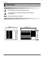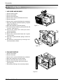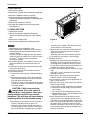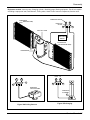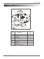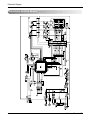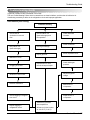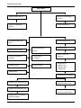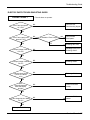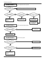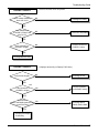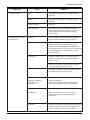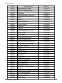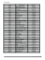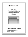
1
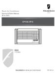
Room Air Conditioner
Service and Parts
Manual
0F
hr
Fan
Speed
Money Fan Cool
Saver ® Only
Dry
Timer
0n/0ff
115Volts
CP06F10
CP06 - CP08 Svc Parts 2010 (05/10)
CP08F10
Mode
Auto
Swing
Temp
Power
Air Conditioner Service Manual
TABLE OF CONTENTS
Safety Precautions..........................................................................................................................................3
Dimensions .....................................................................................................................................................6
Outside Dimensions ...................................................................................................................................6
Product Specifications ..................................................................................................................................7
Operation ........................................................................................................................................................7
Remote Control Operations ......................................................................................................................8
Disassembly ....................................................................................................................................................9
Mechanical Parts........................................................................................................................................9
Air Handling Parts ...................................................................................................................................10
Electrical Parts .........................................................................................................................................11
Refrigerating Cycle...................................................................................................................................12
Schematic Diagram.......................................................................................................................................15
Wiring Diagram.........................................................................................................................................15
Electronic Control Device .........................................................................................................................16
Troubleshooting Guide .................................................................................................................................17
Piping System ........................................................................................................................................17
Troubleshooting Guide .............................................................................................................................18
Exploded View ..............................................................................................................................................26
Replacement Parts List ................................................................................................................................27~28
2 Room Air Conditioner
Safety Precautions
Safety Precautions
To prevent injury to the user or other people and property damage, the following instructions
must be followed.
Incorrect operation due to ignoring instructions will cause harm or damage. The seriousness
is classified by the following indications.
WARNING
This symbol indicates the possibility of death or serious injury.
CAUTION
This symbol indicates the possibility of injury or damage to property only.
Meanings of symbols used in this manual are as shown below.
Be sure not to do.
Be sure to follow the instruction.
WARNING
Always install the expansion panel(s).
• Improper assembly or installation may cause
incorrect operation, including injury, fire, and
electric shock hazards.
Do not use the power cord near flammable
gas or combustibles such as gasoline,
benzene, thinner, etc.
• It may cause explosion or fire.
Do not place the power cord near a heater.
• It may cause fire and electric shock.
Do not disassemble or modify products.
• It may cause failure and electric shock.
Service Manual 3
Safety Precautions
Plug in the power plug
properly.
• Otherwise, it will cause
electric shock or fire.
Do not modify po
power
wer cord
length.
• It will cause electric shock or
fire.
Ventilate before operating air
conditionerwhen gas goes
out.
• It may cause explosion, fire,
and burn.
4 Room Air Conditioner
Do not operate or stop the
unit by inserting or pulling
out the power plug.
Do not damage or use an
unspecified power cord.
• It will cause electric shock or
fire.
• It will cause electric shock or
fire.
Use the air conditioner on a
single outlet circuit.(see page 7.)
Do not share the outlet with
other appliances.
• It will cause electric shock or
fire.
Do not use the socket if it is
loose or damaged.
• It may cause fire and electric
shock.
Always plug into a
grounded outlet.
• No grounding may cause
electric shock.
Do not operate with wet
hands or in damp
environment.
• It will cause electric shock.
Safety Precautions
If water enters the product, turn off the the
power switch of the main body of appliance.
Contact service center after taking the powerplug out from the socket.
• It will cause electric shock or failure of
machine.
Do not clean the air conditioner with water.
• Water may enter the unit and degrade the
insulation. It may cause an electric shock.
CAUTION
Never touch the metal parts of the unit
when removing the filter.
Do not block the inlet or outlet.
• They are sharp and may cause injury.
• It may cause failure of appliance or
performance deteriorate.
Ensure that the outer caseis not damaged
by age orwear.
Be cautious not to touch the sharp edges
• installing.
when
• Leaving it damaged couldresult in the air
conditioner falling out of the window, creating
a safety hazard.
• It may cause injury.
Sharp
edges
Service Manual 5
Dimensions
Dimensions
Symbols Used in this Manual
This symbol alerts you to the risk of electric shock.
This symbol alerts you to hazards that could cause harm to the
air conditioner.
NOTICE
This symbol indicates special notes.
Outside Dimensions
11/ 16")
470(18 1/2")
353(13 7/8")
525(20
6 Room Air Conditioner
Specfications
Product Specifications
MODLES
ITEMS
CP06F10
CP08F10
POWER SUPPLY
1Ø, 115, 60Hz
COOLING CAPACITY
(Btu/h)
7,800
6,000
INPUT
(W)
720
560
6.8
5.1
10.8
10.7
RUNNING CURRENT
(A)
E.E.R (BTU/W.h)
OPERATING
INDOOR
。
( F)
80 (DB)* 67 (WB)**
。
95 (DB)* 75 (WB)**
OUTDOOR ( F)
REFRIGERANT (R410A) CHARGE
345g(12.2 oz)
315g(11.1 oz)
EVAPORATOR
Ø7.0, 3ROW 14STACKS
Ø7.0, 2ROW 14STACKS
CONDENSER
Ø5.0, 3ROW 16STACKS
Ø5.0, 2ROW 16STACKS
FAN, INDOOR
TURBO FAN
FAN, OUTDOOR
PROPELLER TYPE FAN WITH SLINGER RING
FAN SPEEDS, FAN/COOLING
3/3
FAN MOTOR
6 POLES
OPERATION CONTROL
REMOTE CONTROLLER
ROOM TEMP. CONTROL
THERMISTOR
AIR DIRECTION CONTROL
HORIZONTAL LOUVER (UP & DOWN), VERTICAL LOUVER (RIGHT&LEFT)
CONSTRUCTION
PROTECTOR
SLIDE IN-OUT CHASSIS
COMPRESSOR
F A N MO T O R
OVERLOAD PROTECTOR
INTERNAL THERMAL PROTECTOR
3 WIRE WITH GROUNDING
POWER CORD
ATTACHMENT PLUG (CORD-CONNECTED TYPE)
DRAIN SYSTEM
DRAIN PIPE OR SPLASHED BY FAN SLINGER
OUTSIDE D IMENSION
(inch)
(W x H x D)
(mm)
18 1/2 x 13 7/8 x 20 11/16
469 x 353 x 526
* DB:Dry Bulb
** WB:Wet Bulb
Operation
•
•
•
•
•
•
DESIGNED FOR COOLING ONLY
POWERFUL AND INCREDIBLE COOLING
TOP-DOWN CHASSIS FOR THE SIMPLE INSTALLATION AND SERVICE
BUILT-IN ADJUSTABLE THERMOSTAT
WASHABLE ONE-TOUCH FILTER
COMPACT SIZE
Service Manual 7
4
6
7
A ir
P urifier
Power
1
0F
Temp
hr
Fan
Speed
2
Fan S peed
Money
Saver ®
Fan Cool
Only
Dry
4
Auto
Swing
5
Temp
T imer
3
Auto
Swing
Timer
0n/0ff
Mode
5
3
6
Power
2
dry operation.
(dehumidify operation)
Mode
A
S wing
1
6. AUTO SWING
This button can automatically control the air flow
direction.
7
To receive the signal from remote controller.
8 Room Air Conditioner
Disassembly
Disassembly
— Before the following disassembly, POWER SWITCH set to OFF and disconnect the power cord.
Mechanical Parts
1. FRONT GRILLE
1. Open the lnlet grille upward or downward.
2. Remove the screw which fastens the front grille.
3. Pull the front grille from the right side.
4. Remove the front grille.
5. Re-install the component by referring to the
removal procedure, above.(See Figure 1)
Figure 1
2. CABINET
1. After disassembling the FRONT GRILLE, remove
the 2 screws which fasten the cabinet at both
sides.
2. Remove the 2 screws which fasten the cabinet at
back.
3. Pull the base pan forward. (See Figure 2)
4. Remove the cabinet.
5. Re-install the component by referring to the
removal procedure, above.
Figure 2
3. CONTROL BOX
1. Disconnect the unit from the power source.
2. Remove the front grille.
3. Remove the cabinet.
4. Remove the screw which fastens the control box
cover.
5. Remove the housing which connects motor wire
in the control box.
6. Remove the 3 leads from the compressor.
7.Discharge the capacitor by placing a 20,000
ohmresistor across the capacitor terminals.
8. Remove the 2 screws which fasten the control
box.(See Figure 3)
9. Pull the control box forward completely.
10. Re-install the components by referring to the
removal procedure, above. (See Figure 3)
Figure 3
Service Manual 9
Disassembly
Air Handling Parts
1.AIR GUIDE AND BLOWER
1. Remove the front grille.
2. Remove the cabinet.
3. Remove the control box.
4. Remove the 3 screws which fasten the brace.
5. Remove the brace.
6. Remove the 2 screws which fasten the evaporator.
7. Move the evaporator forward and pulling it upward
slightly. (See Figure 4)
8. Move the evaporator to the left carefully.
9. Pull out the hook of orifice by pushing the tabs and
remove it. (See Figure 5)
10. Remove the clamp with a hand plier which
secures the blower.
11. Remove the blower.
12. Remove the 4 screws which fasten the air guide
from the barrier.
13. Move the air guide backward, pulling out from the
base pan.
14. Re-install the components by referring to the
removal procedure, above.
Figure 4
Figure 5
2.FAN AND SHROUD
1. Remove the cabinet.
2. Remove the brace.
3. Remove the 3 screws which fasten the condenser.
4. Move the condenser to the left carefully.
5. Remove the clamp which secures the fan.
6. Remove the fan and then pull out the shroud.
(See Figure 6)
7. Re-install by referring to the removal procedure.
Figure 6
10 Room Air Conditioner
Disassembly
3. MOTOR
1. Remove the cabinet.
2. Remove the evaporator.
3. Remove the orifice.
4. Remove the blower.
5. Remove the fan.
6. Remove the control box cover and housing of the
motor in the control box.
7. Remove the 2 screws which fasten the motor from
the mount motor. (See Figure 7)
8. Remove the motor.
9. Re-install the components by referring to the
removal procedure, above.(See Figure 7)
Figure 7
Electrical Parts
1. OVERLOAD PROTECTOR
1. Remove the cabinet.
2. Remove the nut which fastens the terminal cover.
3. Remove the terminal cover. (See Figure 8)
4. Remove all the leads from the overload protector.
5. Remove the overload protector.
6. Re-install the component by referring to the
removal procedure, above.
Figure 8
2. COMPRESSOR
1. Remove the cabinet.
2. Discharge the refrigerant system using a FreonTM
Recovery System.
If there is no valve to attach the recovery system,
install one (such as a WATCO A-1) before venting
the FreonTM. Leave the valve in place after
servicing the system.
3. Remove the overload protector.
4. After purging the unit completely, unbraze the
suction and discharge tubes at the compressor
connections.
5. Remove the 3 nuts and the 3 washers which
fasten the compressor.
6. Remove the compressor. (See Figure 9)
7. Re-install the components by referring to the
removal procedure, above.
Figure 9
Service Manual 11
Disassembly
3. CAPACITOR
1. Remove the control box.
2. Remove the screw which fasten control panel from
control box.
3. Remove the screw which located in the front.
4. Open the bottom side of control box.
5. Remove the screw and the clamp which fastens
the capacitor.
6. Disconnect all the leads of capacitor terminals.
7. Re-install the components by referring to the
removal procedure, above. (See Figure 10)
Figure 10
4. POWER CORD
1. Remove the control box.
2. Open the control box.
3. Disconnect the grounding screw from the control
box.
4. Disconnect the 2 receptacles.
5. Remove a screw which fastens the clip cord.
(See Figure 11)
6. Remove the power cord.
7. Re-install the component by referring to the above
removal procedure, above.
(Use only one ground-marked hole
for ground
connection.)
8. If the supply cord of this appliance is damaged, it
must be replaced by the special cord. (The
special cord means the cord which has the same
specification marked on the supply cord attached at
the unit.)
Figure 11
Refrigerating Cycle
CAUTION: Discharge the refrigerant system using a Freon TM Recovery System. If there is no valve
to attach the recovery system, install one (such as a WATCO A-1) before venting the FreonTM. Leave
the valve in place after servicing the system.
1. CONDENSER
1. Remove the cabinet.
2. Remove the 3 screws which fasten the
brace.
3. Remove the 3 screws which fasten the condenser
and shroud.
4. After discharging the refrigerant completely,
unbraze the interconnecting tube at the condenser
connections.
5. Remove the condenser carefully.
6. Re-install the component by referring to notes.
(See Figure 12)
Figure 12
12 Room Air Conditioner
Disassembly
2. EVAPORATOR
1. Remove the cabinet.
2. Remove the 2 screws which fasten the evaporator.
3. Move the evaporator sideways carefully.
4. After discharging the refrigerant completely,
unbraze the interconnecting tube at the evaporator
connections.
5. Remove the evaporator carefully.
6. Re-install the component by referring to notes.
(See Figure 13)
3. CAPILLARY TUBE
1. Remove the cabinet.
2. After discharging the refrigerant completely,
unbraze the interconnecting tube at the capillary
tube.
3. Remove the capillary tube.
4. Re-install the component by referring to notes.
NOTICE
— Replacement of the refrigeration cycle.
1. When replacing the refrigeration cycle, be sure to
Discharge the refrigerant system using a FreonTM
recovery System.
If there is no valve to attach the recovery system,
install one (such as a WATCO A-1) before venting
the FreonTM. Leave the valve in place after
servicing the system.
2. After discharging the unit completely, remove the
desired component, and unbraze the pinch-off
tubes.
3. Solder service valves into the pinch-off tube ports,
leaving the valves open.
4. Solder the pinch-off tubes with Service valves.
5. Evacuate as follows.
1) Connect the vacuum pump, as illustrated figure
14A.
2) Start the vacuum pump, slowly open manifold
valves A and B with two full turns counterclockwise and leave the valves open.
The vacuum pump is now pulling through valves
A and B up to valve C by means of the manifold
and entire system.
CAUTION: If high vacuum equipment is used, just crack valves A
and B for a few minutes, then open
slowly with the two full turns counterclockwise. This will keep oil from foaming
and being drawn into the vacuum pump.
3) Operate the vacuum pump vaccum for 20 to 30
minutes, until 600 microns of vaccum is
obtained. Close valves A and B, and observe
vacuum gauge for a few minutes. A rise in pressure would indicate a possible leak or moisture
13 Room Air Conditioner
Figure 13
remaining in the system. With valves A and B
closed, stop the vacuum pump.
4) Remove the hose from the vacuum pump and
place it on the charging cylinder. See figure
37B. Open valve C.
Discharge the line at the manifold connection.
5) The system is now ready for final charging.
6. Recharge as follows :
1) Refrigeration cycle systems are charged from
the High-side. If the total charge cannot be put
in the High-side, the balance will be put in the
suction line through the access valve which you
installed as the system was opened.
2) Connect the charging cylinder as shown in figure
15B.
With valve C open, discharge the hose at the
manifold connection.
3) Open valve A and allow the proper charge to
enter the system. Valve B is still closed.
4) If more charge is required, the high-side will not
take it. Close valve A.
5) With the unit running, open valve B and add the
balance of the charge.
a. Do not add the liquid refrigerant to the Low-side.
b. Watch the Low-side gauge; allow pressure to
rise to 39 lbs.
c. Turn off valve B and allow pressure to drop.
d. Repeat steps b. and c. until the balance of the
charge is in the system.
6) When satisfied the unit is operating correctly,
use the pinch-off tool with the unit still running
and clamp on to the pinch-off tube. Using a tube
cutter, cut the pinch-off tube about 2 inches from
the pinch-off tool. Use sil-fos braze and braze
pinch-off tube closed. Turn off the unit, allow it to
set for a while, and then test the leakage of the
pinch-off connection.
Disassembly
Equipment needed: Vacuum pump, Charging cylinder, Manifold gauge, Brazing equipment. Pin-off tool capable
of making a vapor-proof seal, Leak detector, Tubing cutter, Hand Tools to remove components, Service valve.
COMPOUND GAUGE
CONDENSER
(HIGH PRESSURE SIDE)
MANIFOLD
GAUGE
A
B
CAPILLARY TUBE
SEE INSETS
BELOW
EVAPORATOR
(LOW PRESSURE SIDE)
COMPRESSOR
LOW
HI
A
B
B
A
EXTERNAL
VACUUM PUMP
CHARGING
CYLINDER
C
Figure 14A-Pulling Vacuum
Figure 15B-Charging
Service Manual 14
Schematic Diagram
Circuit Diagram
WH
(BL)
(SMPS)
250V/T2A
(250V/T3.15A)
MEZ62420707
LOCATION
DESCRIPTION
NO.
Q'TY
PER SET
1
POWER CORD ASSEMBLY
1
2
FAN MOTOR
1
3
COMPRESSOR
1
4
DISPLAY P.W.B ASSEMBLY
1
5
MAIN P.W.B ASSEMBLY
1
6
THERMISTOR
1
7
CAPACITOR
1
8
OWERLOAD PROTECTOR
1
15 Room Air Conditioner
Schematic Diagram
Electronic Control Device
Service Manual 16
Troubleshooting Guide
Troubleshooting Guide
Piping System
CONDENSER COIL
FAN
CAPILLARY TUBE
MOTOR
COMPRESSOR
BLOWER
EVAPORATOR COIL
Figure 16 is a brief description of the important components and their function in what is called the refrigeration
system. This will help you to understand the refrigeration cycle and the flow of the refrigerant in the cooling cycle.
ROOM AIR CONITIONER
CYCLE OF REFRIGERATION
EVAPORATOR COILS
CONDENSER COILS
COMPLETE LIQUID
BOIL OFF POINT
COOLED
AIR
SUCTION LINE
COOL LOW PRESSURE VAPOR
VAPOR INLET
HOT
DISCHARGED
AIR
ROOM AIR HEAT LOAD
MOTOR
OUTSIDE COOLING
AIR FOR REFRIGERANT
PASS THROUGH
COMPRESSOR
OIL
LIQUID
PRESSURE
DROP
LIQUID OUTLET
(LIQUID REFRIGERANT)
Figure 16
17 Room Air Conditioner
HIGH PRESSURE VAPOR
LIQUID REFRIGERANT
CAPILLARY TUBE
LOW PRESSURE VAPOR
Troubleshooting Guide
Troubleshooting Guide
In general, possible trouble is classified in two kinds.
The one is called Starting Failure which is caused from an electrical defect, and the other is ineffective Air
Conditioning caused by a defect in the refrigeration circuit and improper application.
Unit runs but poor cooling.
Ineffective Cooling
Check cold air
circulation for smooth
flow.
Check outdoor coil
(heat exchanger) and
fan operation.
Dirty indoor coil
(heat exchanger)
Check gas leakage.
Check heat load
increase.
Clean condenser.
Not on separate circuit
Repair gas leak.
Malfunction of fan.
Clogging of air filter.
Replacement of unit if
the unit is beyond repair.
Check inside gas
pressure.
Adjust refrigerant
charge.
Obstruction at air outlet.
Remove obstruction.
Malfunction of
compressor.
Check clogging in refrigeration circuit.
Replacement of
compressor.
Repair clogging in
refrigeration circuit.
Satisfactory operation
with temperature
difference of inlet & outlet
air; 44~50°F (7~10°C)
Service Manual 18
Troubleshooting Guide
Fails to Start
Check of power source.
Check of circuit breaker
and fuse.
Check of control panel
setting.
Check control panel.
Compressor fails only to
start.
Fan only fails to start.
Drop of power voltage.
Defect of compressor
capacitor.
Capacitor check.
Improper thermistor
setting
Loose terminal
connection
Improper wiring
Improper wiring.
Defect of fan motor
capacitor.
Irregular motor
resistance (Ω)
Irregular motor
insulation (Ω)
Replacement.
Replacement of fan motor.
Irregular motor resistance (Ω)
Irregular motor insulation (Ω)
Replacement of compressor
(Motor damaged).
19 Room Air Conditioner
Regular but fails to start.
Replacement of compressor.
(Locking of piston, metal.)
Troubleshooting Guide
ELECTRIC PARTS TROUBLESHOOTING GUIDE:
Possible Trouble 1
Is the Trans input power
AC 115V?
• The unit does not operate.
NO
• Check the Fuse.
• Check the wiring diagram.
YES
Is the Trans output power
about AC 14V?
NO
YES
Is output Voltage of IC01D
DC 12V?
Is shorted the Trans. output?
YES
NO
NO
• Check the Main
P.W.B pattern.
• Exchange the Trans.
• Exchange D02D~D05D.
• Exchange IC01D.
YES
Is output Voltage of IC02D
DC 5V?
NO
• Exchange IC02D.
YES
Is the reset circuit all right?
(The No.14 of Micom
is 5V.)
NO
• Exchange IC01A.
YES
Is the
connection between
Main and Display
all right?
NO
• Connect connector
exactly.
NO
• Check the P.W.B
pattern.
YES
Is the voltage No.18 of Micom
DC 5V?
YES
Exchange Main P.W.B Ass'y.
Service Manual 20
Troubleshooting Guide
Possible Trouble 2
• The compressor does not operate.
Is Temp.
NO
setting set lower than Room
Temp.-0.5°C?
• Set the Temp. setting to lower Temp.
YES
Is the voltage No.10
of IC01M 0V?
NO
Is the voltage N0.7 of
IC01M DC 5V?
NO
YES
YES
• Check the RY-COMP.
• Check the wiring
Diagram.
• Exchange IC01M.
Is the Unit for 3 minutes
delay?
NO
YES
• Wait 3 Minutes
• Exchange MAIN
P.W.B Ass'y.
Possible Trouble 3
Is the wire connection of
RY-COMP all right?
• The compressor always operate.
• Connect LEAD Wire to
RY-COMP again.
NO
YES
• Check the RY-COMP.
Possible Trouble 4
Is the voltage NO.1 or 4
of IC01M DC 5V?
• Fan does not operate.
NO
• Exchange IC01M.
YES
Is the voltage NO.13 or 16
of IC01M 0V?
YES
• Check the RY-Hi or
RY-Lo.
• Check the wiring diagram.
21 Room Air Conditioner
NO
• Exchange IC01M.
Troubleshooting Guide
• Romote controller does not operate.
Possible Trouble 5
Is the voltage of Battery
about over 2.3V?
NO
• Exchange the battery.
YES
Is the voltage No.16
of CN-DISP1 on Main P.W.B
Ass'y DC 5V?
NO
• Check the P.W.B pattern.
YES
NO
Is the connection of
CN-DISP1 all right?
• Connect connector to
CN-DISP1 exactly.
YES
• Exchange Receiver Ass'y.
Possible Trouble 6
Is the IC01G all right?
• It displays abnormally on Display P.W.B Ass'y.
NO
• Exchange IC01G.
YES
NO
Is the connection of
CN-DISP1 all right?
NO
• Connect connector
to CN-DISP1 exactly.
YES
Does the Q01G,
Q02G, Q03G Q04G operate normally
on main P.W.B Ass'y?
NO
• Exchange Q01G,
Q02G, Q03G, Q04G
YES
• Exchange the display
P.W.B Ass'y.
Service Manual 22
Troubleshooting Guide
ROOM AIR CONDITIONER VOLTAGE LIMITS
NAME PLATE RATING
MINIMUM
MAXIMUM
115V ± 10%
103.5V
126.5V
COMPLAINT
Fan motor will not run.
CAUSE
REMEDY
No power
Check voltage at outlet. Correct if none.
Wire disconnected or
connection loose
Connect wire. Refer to wiring diagram for
terminal identification. Repair or replace loose
terminal.
Capacitor (Discharge
capacitor before testing.)
Test capacitor.
Replace if not within ±10% of manufacturer's
rating. Replace if shorted, open, or damaged.
Will not rotate
Fan blade hitting shroud or blower wheel hitting
scroll. Re-align assembly.
Units using slinger ring condenser fans must
have 0.22~0.25 inch clearance to the base.
If necessary, shim up the bottom of the fan motor
with mounting screw(s).
Check fan motor bearings; if motor shaft will not
rotate, replace the motor.
Fan motor runs.
Revolves on overload
Check voltage. See limits on this page.
If not within limits, call an electrician.
Test capacitor.
Check bearings. Does the fan blade rotate
freely?
If not, replace fan motor.
Pay attention to any change from high speed to
low speed. If the speed does not change,
replace the motor.
23 Room Air Conditioner
Troubleshooting Guide
COMPLAINT
Fan motor noise.
Compressor will not run,
fan motor runs.
CAUSE
REMEDY
Fan
If cracked, out of balance, or partially missing,
replace it.
Blower
If cracked, out of balance, or partially missing,
replace it.
Loose set screw
Tighten it.
Worn bearings
If knocking sounds continue when running or
loose, replace the motor. If the motor hums or
noise appears to be internal while running,
replace motor.
Voltage
Check voltage. See the limits on the preceding
page. If not within limits, call an electrician.
Wiring
Check the wire connections; if loose, repair or
replace the terminal. If the wires are disconnected, refer to wiring diagram for identification,
and replace the wires. Check the wire connections;
If not according to the wiring diagram, correct
the connections.
Thermistor
Check the TEMP control. If not at the lowest
number, set TEMP control to this setting and
restart the unit.
Check the continuity of the thermistor. Replace
the thermistor if the circuit is open.
Check the continuity of the thermostat. Replace
the thermostat if the circuit is open.
Capacitor (discharge
capacitor before
servicing.)
Check the capacitor.
Replace if not within ±10% of manufacturer’s
rating, replace if shorted, open, or damaged.
Compressor
Check the compressor for open circuit or
ground. If open or grounded, replace the
compressor.
Overload
Check the compressor overload if externally mounted.
Replace if open. (If the compressor temperature is
high, remove the overload, cool, and retest.)
Service Manual 24
Troubleshooting Guide
COMPLAINT
Compressor cycles on
overload.
Compressor cycles on
overload.
Insufficient cooling
Excessive noise
25 Room Air Conditioner
CAUSE
REMEDY
Voltage
Check the voltage. See the limits on the
preceding page. If voltage is not within these limits,
call an electrician.
Overload
Check overload, if externally mounted.
Replace if open. (If the compressor temperature
is high, remove the overload, cool, and retest.)
Fan motor
If not running, determine the cause. Replace if
required.
Condenser air flow
restriction
Remove the cabinet, inspect the interior surface
of the condenser. If restricted, clean carefully
with a vacuum cleaner (do not damage fins) or
brush. Clean the interior base before
re-assembling.
Condenser fins
(damaged)
If the condenser fins are closed over a large
area on the coil surface, head pressures will
increase, causing the compressor to cycle.
Straighten the fins or replace the coil.
Capacitor
Test the capacitor.
Wiring
Check the terminals. If loose, repair or replace.
Refrigeration system
Check the system for a restriction.
Air filter
If restricted, clean or replace.
Unit undersized
Determine if the unit is properly sized for the
area to be cooled.
Blower or fan
Check the set screw, or clamp. If loose or missing, correct. If the blower or fan is hitting scroll
or barrier, rearrange the air handling parts.
Copper tubing
Remove the cabinet and carefully rearrange the
tubing not to contact the cabinet,
compressor, shroud, and barrier.
Exploded View
Exploded View
130910
731273
148000
359011
346811
352380
W48602
749740
349600
149980
359012
267110
552113
349001
349480
567502
135303
152302
147582
130410
550140
135312
147581
249950
567480
W0CZZ
268711-1
238310
146812
264110
237200
268711-2
135500
Service Manual 26
Replacement Parts list
LocNo
DESCRIPTION
CP06F10
130410
Base Assembly,Single
67302912
130910
Cabinet Assembly,Single
67303714
135303
Grille,Inlet
67306114
135312
Grille Assembly,Front(Indoor)
67306017
135500
Cover
67400148
146812
Motor,AC
67300902
147581
Louver,Horizontal
67306208
147582
Louver,Vertical
67306264
148000
Supporter
67303901
149980
Shroud
67303108
152302
Filter Assembly,Air Cleaner
67304309
237200
Panel,Control
67305512
238310
Escutcheon
67500142
249950
Case Assembly,Control
67305511
264110
Power Cord Assembly
67300020
267110
Remote Controller Assembly
67302232
346811
Motor Assembly,AC,Single
67303013
349001
Damper Assembly
67303502
349480
Orifice
67303412
349600
Bracket,Motor
67303604
352380
Duct Assembly
67302736
359011
Fan,Axial
67303203
359012
Fan,Turbo
67302609
550140
Damper,Compressor
67301900
567480
Thermistor,NTC
67307806
567502
Overload Protect
67301912
731273
Install Part Assembly,Single
67306312
749740
Guide
67304011
268711-1
PWB(PCB) ASSEMBLY,DISPLAY
67307621
268711-2
PCB Assembly,Main
67307622
W0CZZ
Capacitor,Film,Box
67300718
W48602
Clamp,Spring
67302500
27 Room Air Conditioner
ReplacementParts list
LocNo
DESCRIPTION
CP08F10
130410
Base Assembly,Single
67302917
130910
Cabinet Assembly,Single
67303714
135303
Grille,Inlet
67306114
135312
Grille Assembly,Front(Indoor)
67306017
135500
Cover
67400148
146812
Motor,AC
67300902
147581
Louver,Horizontal
67306208
147582
Louver,Vertical
67306264
148000
Supporter
67303901
149980
Shroud
67305533
152302
Filter Assembly,Air Cleaner
67304309
237200
Panel,Control
67305512
238310
Escutcheon
67500142
249950
Case Assembly,Control
67305513
264110
Power Cord Assembly
67300020
267110
Remote Controller Assembly
67302232
346811
Motor Assembly,AC,Single
67303005
349001
Damper Assembly
67303502
349480
Orifice
67303412
349600
Bracket,Motor
67303604
352380
Duct Assembly
67302736
359011
Fan,Axial
67303203
359012
Fan,Turbo
67302609
550140
Damper,Compressor
67305000
567480
Thermistor,NTC
67307806
567502
Overload Protect
67301913
731273
Install Part Assembly,Single
67306312
749740
Guide
67304011
268711-1
PWB(PCB) ASSEMBLY,DISPLA
67307621
268711-2
PCB Assembly,Main
67307622
35211A
Tube Assembly,Suction
67307622
W0CZZ
Capacitor,Film,Box
67302726
W48602
Clamp,Spring
67302500
Service Manual 28
Use Factory Certified Parts...
FRIEDRICH AIR CONDITIONING CO.
Visit our web site at www.friedrich.com
Post Office Box 1540 • 4200 N. Pan Am Expressway • San Antonio, Texas 78295-1540
• (210) 357-4400 • FAX (210) 357-4490
CP06 - CP08 Svc Parts 2010 (05/10)