1
Uni- Fit
R
Thru-the-Wall Series
Service and Parts
Manual
Thru-the-Wall Series
230 Volts UE10C33 UE12C33
115 Volts UE08C13
Unifit Heat Cool Svc Parts 2010 (05/10)
Unifit. Cool (03/07)
Air Conditioner Service Manual
TABLE OF CONTENTS
Safety Precautions ..........................................................................................................................................3
Operating Instructions ..................................................................................................................................7
Controls.................................................................................................................................................... 7
Remote control......................................................................................................................................... 8
Disassembly instructions ............................................................................................................................. 9
Mechanical Parts...................................................................................................................................... 9
Air Handling Parts ...................................................................................................................................10
Electrical Parts ........................................................................................................................................11
Refrigeration Cycle..................................................................................................................................13
Schematic Diagram........................................................................................................................................16
Wiring Diagram........................................................................................................................................16
Troubleshooting Guide ................................................................................................................................17
Piping System .........................................................................................................................................17
Troubleshooting Guide ............................................................................................................................18
Room Air Conditioner Voltage Limits.......................................................................................................21
Product specifications...............................................................................
.................................................................23~25
Exploded Vi ew .............................................................................................................................................26
Replacement Parts List ...............................................................................................................................27~29
2 Room Air Conditioner
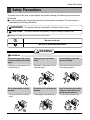
Safety Precautions
Safety Precautions
To prevent injury to the user or other people and property damage, the following instructions must
be followed.
■ Incorrect operation due to ignoring instruction will cause harm or damage. The seriousness is
classified by the following indications.
WARNING
This symbol indicates the possibility of death or serious injury.
CAUTION
This symbol indicates the possibility of injury or damage to property only.
■ Meanings of symbols used in this manual are as shown below.
Be sure not to do.
Be sure to follow the instruction.
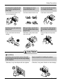
WARNING
■ Installation
Don’t use a power cord, a plug
or a loose socket which is damaged.
• Otherwise, it may cause a fire or
electrical shock.
Always plug into a grounded
outlet.
• Otherwise, it may cause a fire or
electrical shock.
Do not modify or extend the
power cord length.
• It will cause electric shock or fire
due to heat generation.
Cool
Energy
Saver
Fan
Heat
MODE
Cool
Energy
Saver
Timer
TIMER
F1
F2 LOW
HIGH
TEMP
'F
FAN
SPEED
Fan
Heat
MODE
Timer
TIMER
POWER
F1
F2 LOW
HIGH
TEMP
'F
FAN
SPEED
POWER
Do not disassemble or modify
products.
Be caution when unpacking and
installing.
Do not use the power cord near flammable gas or combustibles such as
gasoline, benzene, thinner, etc.
• It may cause failure and electric
shock.
• Sharp edges may cause injury.
• It may cause explosion or fire.
Cool
Energy
Saver
Fan
Heat
MODE
Timer
TIMER
F1
F2 LOW
HIGH
TEMP
'F
FAN
SPEED
POWER
Cool
Energy
Saver
Fan
Heat
MODE
Timer
TIMER
Cool
Energy
Saver
F1
F2 LOW
HIGH
TEMP
'F
FAN
SPEED
Fan
POWER
Heat
MODE
Timer
TIMER
F1
F2 LOW
HIGH
TEMP
'F
FAN
SPEED
POWER
Gasolin
Service Manual 3
Safety Precautions
■ Operation
Do not place heavy object on the
power cord and take care so that
the cord should not be pressed.
• There is danger of fire or electric
shock.
Do not share the outlet with
other appliances.
Take the power plug out if necessary, holding the head of the plug
and do not touch it with wet hands.
• It will cause electric shock or fire
due to heat generation.
• Otherwise, it may cause a fire or
electrical shock.
Cool
Energy
Saver
Fan
Heat
MODE
Timer
TIMER
F1
F2 LOW
HIGH
TEMP
'F
Cool
Energy
Saver
FAN
SPEED
Fan
POWER
Heat
MODE
Timer
TIMER
F1
F2 LOW
HIGH
'F
TEMP
FAN
SPEED
POWER
Do not place the power cord
near a heater.
• It may cause fire and electric
shock.
Do not allow water to run into
electric parts.
• It will cause failure of machine or
electric shock.
Use a soft cloth to clean. Do not
use wax, thinner, or a strong
detergent.
• The appearance of the air conditioner may deteriorate, change
color, or develop surface flaws.
Cool
Energy
Saver
Fan
Heat
MODE
Timer
TIMER
F1
F2 LOW
HIGH
TEMP
'F
FAN
SPEED
POWER
Cool
Energy
Saver
Fan
Heat
MODE
Timer
TIMER
F1
F2 LOW
HIGH
TEMP
'F
FAN
SPEED
POWER
Cool
Energy
Saver
Fan
Heat
MODE
Timer
TIMER
F1
F2 LOW
HIGH
TEMP
'F
FAN
SPEED
POWER
x
Wa Thinner
Unplug the unit if strange
sounds, odors, or smoke come
from it.
• Otherwise it may cause fire and
electric shock accident.
Do not open the suction inlet
grill of the product during operation.
If water enters the product, turn off the the
power switch of the main body of appliance.
Contact service center after taking the
power-plug out from the socket.
• Otherwise, it may electrical
shock and failure.
Cool
Energy
Saver
Fan
Heat
MODE
Timer
TIMER
F1
F2 LOW
HIGH
TEMP
'F
FAN
SPEED
POWER
Cool
Energy
Saver
Fan
Heat
MODE
Timer
TIMER
F1
F2 LOW
HIGH
TEMP
'F
FAN
SPEED
POWER
Cool
Energy
Saver
Fan
Heat
MODE
Timer
TIMER
F1
F2 LOW
HIGH
TEMP
'F
FAN
SPEED
POWER
Ventilate the room well when
using this appliance together
with a stove, etc.
• An oxygen shortage may occur.
Turn off the power and breaker
firstly when cleansing the unit.
Turn off the main power switch
when not using it for a long
time.
• Since the fan rotates at high speed
during operation, it may cause
injury.
• Prevent accidental startup and the
possibility of injury.
Cool
Energy
Saver
Fan
Heat
MODE
Timer
TIMER
F1
F2 LOW
HIGH
TEMP
'F
FAN
SPEED
POWER
Cool
Energy
Saver
Fan
Heat
MODE
Timer
TIMER
F1
F2 LOW
HIGH
TEMP
'F
FAN
SPEED
POWER
Cool
Energy
Saver
Fan
Heat
MODE
Timer
TIMER
F1
F2 LOW
HIGH
TEMP
'F
FAN
SPEED
POWER
4 Room Air Conditioner
Safety Precautions
Do not operate or stop the unit
by inserting or pulling out the
power plug.
• It will cause electric shock or fire
due to heat generation.
Do not damage or use an
unspecified power cord.
• It will cause electric shock or fire.
Do not operate with wet hands
or in damp environment.
• It will cause electric shock.
Cool
Energy
Saver
Fan
Heat
MODE
Timer
TIMER
F1
F2 LOW
HIGH
TEMP
'F
FAN
SPEED
POWER
Cool
Energy
Saver
Fan
Heat
MODE
Timer
TIMER
F1
F2 LOW
HIGH
TEMP
'F
FAN
SPEED
POWER
Hold the plug by the head when
taking it out.
• It may cause electric shock and
damage.
When gas leaks, open the window for ventilation before operating the unit.
• Otherwise, it may cause explosion, and a fire.
Never touch the metal parts of
the unit when removing the filter.
• They are sharp and may cause
injury.
Cool
Energy
Saver
Fan
Heat
MODE
Timer
TIMER
F1
F2 LOW
HIGH
TEMP
'F
FAN
SPEED
POWER
Cool
Energy
Saver
Fan
Heat
MODE
Timer
TIMER
F1
F2 LOW
HIGH
TEMP
'F
FAN
SPEED
POWER
CAUTION
■ Installation
Install the product so that the noise or hot wind
from the outdoor unit may not cause any damage
to the neighbors.
• Otherwise, it may cause dispute with the neighbors.
Keep level parallel in installing the product.
• Otherwise, it may cause vibration or water leakage.
Cool
Energy
Saver
Fan
Heat
F1
F2 LOW
HIGH
Timer
MODE
TEMP
'F
TIMER
FAN
SPEED
POWER
Service Manual 5
Safety Precautions
■ Operation
Do not put a pet or house plant
where it will be exposed to
direct air flow.
• It may cause injury.
Do not block the inlet or outlet
of air flow.
• It may cause product failure.
Use a soft cloth to clean. Do not
use wax, thinner, or a strong
detergent.
• The appearance of the air conditioner may deteriorate, change
color, or develop surface flaws.
Cool
Energy
Saver
Fan
Heat
MODE
Timer
TIMER
F1
F2 LOW
HIGH
TEMP
'F
FAN
SPEED
POWER
Cool
Energy
Saver
Fan
Heat
MODE
Timer
TIMER
F1
F2 LOW
HIGH
TEMP
'F
FAN
SPEED
Cool
Energy
Saver
POWER
Fan
Heat
MODE
Timer
TIMER
F1
F2 LOW
HIGH
TEMP
'F
FAN
SPEED
POWER
Do not step on the indoor/outdoor unit and do not put anything on it.
Always insert the filter securely.
Clean it every two weeks.
• It may cause an injury through
dropping of the unit or falling
down.
• Operation without filters will cause
failure.
Do not drink water drained from
air conditioner.
• It contains containments and will
make you sick.
Cool
Energy
Saver
Fan
Heat
MODE
Timer
TIMER
F1
F2 LOW
HIGH
TEMP
'F
FAN
SPEED
POWER
Be cautious not to touch the
sharp edges when installing.
• It may cause injury.
Avoid excessive cooling and
perform ventilation sometimes.
• Otherwise, it may do harm to
your health.
Do not insert the hands or bars
through the air inlet or outlet
during operation.
• Otherwise, it may cause personal injury.
Cool
Energy
Saver
Fan
Heat
MODE
Timer
TIMER
F1
F2 LOW
HIGH
TEMP
'F
Cool
Energy
Saver
Fan
FAN
SPEED
Heat
POWER
MODE
Timer
TIMER
F1
F2 LOW
HIGH
TEMP
'F
FAN
SPEED
POWER
Cool
Energy
Saver
Fan
Heat
MODE
Timer
TIMER
F1
F2 LOW
HIGH
TEMP
'F
FAN
SPEED
POWE
R
6 Room Air Conditioner
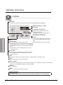
Operating Instructions
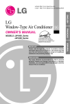
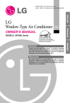
Controls
FAN SPEED
Every time you push this button,it advances the setting as follows:{High[F2]
Low[F1]}
High[F2]
REMOTE CONTROL SIGNAL
RECEIVER
TEMPERATURE SETTING
Use this button to automatically control the
temperature of the room
The tmeperature can be set within a range of
。
。
60 F to 86 F by increments of 1。
F.
The setting appears in the display.
POWER
TIMER
SHUT-OFF TIME
You will usually use shut-off time while you sleep.
To turn the air conditioner ON,push this button.
To turn the air conditioner OFF,push the button
again.
This button takes priority over any other button.
If unit is running,use Timer to set number of hours until shut-off.
For your sleeping comfort,once Timer is set,the Temperature
。
setting will raise 2 F after 30 min,and once again after another
30 min.
Push Timer button to advance setting from 1Hour→ 2Hour →...
→12Hours maximum.
START TIME
If unit is off,use Timer to set number of hours before nuit starts.
Push Timer button to advance setting from 1Hour→ 2Hour →...
→12Hours maximum.
MODE
Push this button to shift mode of operation from COOL → MONEY SAVER→ FAN ONLY→HEAT
COOL:
Fan runs continually for normal cooling operation.
MONEY SAVER:
The fan stops when the compressor stops cooling.Approximately every 3 minutes the fan will turn on and the nuit will
check the room air temperature to determine if cooling is needed.
FAN ONLY:
Fan-only operation.
HEAT:
Fan runs continually for normal heating operation.
AUTO RESTART
When power is restored after an electrical power failure,the unit will begin to run at its last setting.
7 Room Air Conditioner
REMOTE CONTROL
POWER
To turn the air conditioner ON,push this button.
To turn the air conditioner OFF,push the button again.
This button takes priority over any other button.
TEMPERATURE SETTING
Use this button to automatically control the temperature of the room.
The tmeperature can be set within a range of 60。
F to 86。
F by
。
increments of 1 F.
The setting appears in the display.
FAN SPEED
Every time you push this button,it advances the setting as follows:
{High[F2]
Low[F1]}
High[F2]
TIMER
SHUT-OFF TIME
You will usually use shut-off time while you sleep.
If unit is running,use Timer to set number of hours until shut-off.
For your sleeping comfort,once Timer is set,the Temperature setting will
。
raise 2 F after 30 min,and once again after another 30 min.
Push Timer button to advance setting from 1Hour→ 2Hour →...
→12Hours maximum.
START TIME
If unit is off,use Timer to set number of hours before nuit starts.
Push Timer button to advance setting from 1Hour→ 2Hour →...
→12Hours maximum.
MODE
Push this button to shift mode of operation from COOL → MONEY SAVER→ FAN ONLY→HEAT
COOL:
Fan runs continually for normal cooling operation.
MONEY SAVER:
The fan stops when the compressor stops cooling.Approximately every 3 minutes the fan will turn on and the nuit will
check the room air temperature to determine if cooling is needed.
FAN ONLY:
Fan-only operation.
HEAT:
Fan runs continually for normal heating operation.
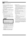
CAUTION
When the air conditioner has been performed its
cooling or feating operation and is turned off or
set to the fan position,wait at 3 minutes
before resetting to the cooling operation again.
A slight heat odor may come from the nuit
when first switching to HEAT after the
cooling season is over.This odor,caused
by fine duct particles on the heater,will
disappear quickly.This is harmless.
Service Manual 8
Disassembly Instructions
Disassembly Instructions
— Before the following disassembly, POWER SWITCH is set to OFF and disconnected the power cord.
Mechanical Parts
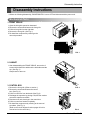
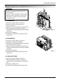
1. FRONT GRILLE
1. Open the inlet grille upward or downward.
2. Remove the screw which fastens the front grille.
3. Pull the front grille from the right side.
4. Remove the front grille. (See Fig. 1)
5. Re-install the component by referring to the
removal procedure.
'F
LOW
F1 HIGH
F2
Cool
y
Energ
Saver
Fan
TEMP
ER
POW
Timer
Heat
R
FAN D
SPEE
TIME
E
MOD
Cool
F1 LOW
F2 HIGH
Energy
Saver
'F
Fan
Heat
MODE
Timer
TIMER
TEMP
FAN
SPEED
POWER
FIG. 1
2. CABINET
1. After disassembling the FRONT GRILLE, remove the 9
screws which fasten the cabinet at the both sides and the
top. (See Fig. 2)
Keep these for later use.
Coo
Ener l
Savegy
r
Fan
F1
F2 LOW
F3 MED
HIGH
Time
MO
'F
r
TEM
P
DE
TIM
ER
FAN
SPE
ED
POW
ER
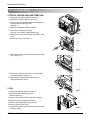
3. CONTROL BOX
1. Remove the front grille. (Refer to section 1)
2. Remove the screw which fasten the control
box. (See Fig. 3)
3. Pull the control box from the barrier.(See Fig.3)
4. Discharge the capacitor by placing a 20,000 ohm resistor
across the capacitor terminals.
5. Disconnect two wire housings in the control box.
6. Pull the control box forward completely.
7. Re-install the components by referring to the removal
procedure. (See Fig. 3)
(Refer to the circuit diagram found on pages 24 in this
manual and on the control box.)
FIG. 2
Co
ol
Ene
Savrgy
er
Fan
F1
F2 LOW
F3 MED
HIGH
MO
DE
Tim
er
'F
TE
MP
TIM
ER
FA
SP N
EE
D
PO
WE
R
FIG. 3
Service Manual 9
Disassembly Instructions
Air Handling Parts
4. ORIFICE, HEATER ASSY AND TURBO FAN
1. Remove the front grille. (Refer to section 1)
2. Remove the cabinet. (Refer to section 2)
3. Remove the 2 screws which fasten the evaporator
at the left side and the right side.
(See Fig. 4)
4. Move the evaporator sideward carefully.
5. Remove the 2 terminals carefully
(See Fig. 28, at Electric Heater Model only)
6. Remove the 4 screws which fasten the orifice. (See
Fig. 5)
7. Remove the orifice. (See Fig. 5)
Coo
Ene l
Savrgy
er
Fan
F1
F2 LOW
F3 MED
HIGH
MO
DE
Tim
er
'F
TEM
TIM
P
ER
FAN
SPE
ED
PO
WE
R
FIG. 4
FIG. 5
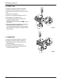
8. Remove the clamp which secures the turbo fan with
plier. (See Fig. 6)
FIG. 6
9. Remove the turbo fan with plier or your hand without touching blades. (See Fig. 7)
10. Re-install the components by referring to the
removal procedure, above.
5. FAN
1. Remove the cabinet. (Refer to section 2)
2. Remove the brace and shroud cover.
(Refer to section 4)
3. Remove the 6 screws which fasten the condenser.
4. Move the condenser sideways carefully.
5. Remove the clamp which secures the fan.
6. Remove the fan. (See Fig. 8)
7. Re-install the components by referring to the removal
procedure, above.
10 Room Air Conditioner
FIG. 7
FIG. 8
Disassembly Instructions
6. SHROUD
1. Remove the fan. (Refer to section 5)
2. Remove the screw which fasten the shroud.
3. Remove the shroud. (See Fig. 9)
4. Re-install the component by referring to the
removal procedure, above.
FIG. 9
Electrical Parts
7. MOTOR
1. Remove the cabinet. (Refer to section 2)
2. Remove the clamp cord and disconnect a wire
housing in control box. (Refer to section 3)
3. Remove the turbo fan. (Refer to section 5)
4. Remove the fan. (Refer to section 5)
5. Remove the 4 or 2 screws which fasten the motor.
(See Fig. 10)
6. Remove the motor.
7. Re-install the components by referring to the
removal procedure, above.
FIG. 10
8. COMPRESSOR
1. Remove the cabinet. (Refer to section 2)
2. Discharge the refrigerant system using FreonTM
Recovery System.
If there is no valve to attach the recovery system,
install one (such as a WATCO A-1) before venting
the FreonTM . Leave the valve in place after
servicing the system.
3. Disconnect the 3 leads from the compressor.
4. After purging the unit completely, unbraze the suction and discharge tubes at the compressor connections.
5. Remove the 3 nuts and the 3 washers which fasten the compressor. (See Fig. 11)
6. Remove the compressor.
7. Re-instill the components by referring to the
removal procedure, above.
9. CAPACITOR
1. Remove the control box. (Refer to section 3)
2. Remove a screw which fasten the display panel.
3. Remove 2 screws and unfold the control box.
(See Fig. 12)
4. Remove the screw and the clamp which fastens
the capacitor. (See Fig. 12)
5. Disconnect all the leads of capacitor terminals.
6. Re-install the components by referring to the
removal procedure, above.
FIG. 11
Coo
Ener l
Savegy
r
Fan
MO
DE
F1
F2 LOW
F3 MED
HIG
H
Tim
er
TIM
ER
'F
TE
MP
FA
SP N
EE
D
PO
WE
R
FIG. 12
Service Manual 11
Disassembly Instructions
10. POWER CORD
1. Remove the control box. (Refer to section 3)
2. Unfold the control box. (Refer to section 9)
3. Disconnect the grounding screw from the control
box.
4. Disconnect 2 receptacles.
5. Remove a screw which fastens the clip cord.
6. Pull the power cord. (See Fig. 13)
7. Re-install the component by referring to the
removal procedure, above.
(Use only one ground-marked hole
for ground
connection.)
8. If the supply cord of this appliance is damaged, it
must be replaced by the special cord.
(The special cord means the cord which has the
same specification marked on the supply cord fitted to the unit.)
Coo
Ener l
Savegy
r
Fan
MO
DE
F1
F2 LOW
F3 MED
HIG
H
Tim
er
TIM
ER
'F
TE
MP
FA
SP N
EE
D
PO
WE
R
FIG. 13
11. THERMOSTAT
1. Remove the control box. (Refer to section 3)
2. Unfold the control box. (Refer to section 9)
3. Disconnect the theristor terminals from main
P.W.B assembly.
4. Remove the thermostat. (See Fig. 14)
5. Re-install the components by referring to the
removal procedure, above.
Coo
Ener l
Savegy
r
Fan
MO
DE
F1
F2 LOW
F3 MED
HIG
H
Tim
er
TIM
ER
'F
TE
MP
FA
SP N
EE
D
PO
WE
R
FIG. 14
12 Room Air Conditioner
Disassembly Instructions
Refrigerating Cycle
CAUTION
Discharge the refrigerant system using FreonTM
Recovery System.
If there is no valve to attach the recovery system,
install one (such as a WATCO A-1) before venting the FreonTM. Leave the valve in place after
servicing the system.
12. CONDENSER
1. Remove the cabinet. (Refer to section 2)
2. Remove the brace and the shroud cover.
(Refer to section 4)
3. Remove the 5 screws which fasten the condenser.
4. After discharging the refrigerant completely,
unbraze the interconnecting tube at the condenser
connections.
5. Remove the condenser.
6. Re-install the components by referring to notes.
(See Fig. 15)
FIG. 15
13. EVAPORATOR
1. Remove the cabinet. (Refer to section 2)
2. Discharge the refrigerant completely.
3. Remove the 2 screws which fasten the evaporator
at the left side and the right side.
4. Move the evaporator sideward carefully and then
unbraze the interconnecting tube at the evaporator
connectors.
5. Remove the evaporator.
6. Re-install the components by referring to notes.
(See Fig. 16)
Coo
Ene l
Savrgy
er
Fan
F1
F2 LOW
F3 MED
HIGH
Tim
er
MO
'F
TE
DE
MP
TIM
ER
FAN
SP
EE
D
PO
WE
R
FIG. 16
14. CAPILLARY TUBE
1. Remove the cabinet. (Refer to section 2)
2. After discharging the refrigerant completely,
unbraze the interconnecting tube at the capillary
tube.
3. Remove the capillary tube.
4. Re-install the components by referring to notes.
Service Manual 13
Disassembly Instructions
NOTICE
— Replacement of the refrigeration cycle.
1. When replacing the refrigeration cycle, be sure to
discharge the refrigerant system using a FreonTM
recovery System.
If there is no valve to attach the recovery system,
install one (such as a WATCO A-1) before venting
the FreonTM. Leave the valve in place after
servicing the system.
2. After discharging the unit completely, remove the
desired component, and unbrace the pinch-off
tubes.
3. Solder service valves into the pinch-off tube ports,
leaving the valves open.
4. Solder the pinch-off tubes with Service valves.
5. Evacuate as follows.
1) Connect the vacuum pump, as illustrated Fig.
17A.
2) Start the vacuum pump, slowly open manifold
valves A and B with two full turns counterclockwise and leave the valves closed.
The vacuum pump is now pulling through valves
A and B up to valve C by means of the manifold
and entire system.
CAUTION
If high vacuum equipment is used, just crack
valves A and B for a few minutes, then open
slowly with the two full turns counterclockwise.
This will keep oil from foaming and being
drawn into the vacuum pump.
3) Operate the vacuum pump for 20 to 30 minutes,
until 600 microns of vacuum is obtained. Close
valves A and B, and observe vacuum gauge for
a few minutes. A rise in pressure would
indicate a possible leak or moisture remaining in
the system. With valves A and B closed, stop
the vacuum pump.
4) Remove the hose from the vacuum pump and
place it on the charging cylinder. See Fig. 17B.
Open valve C.
Discharge the line at the manifold connection.
5) The system is now ready for final charging.
14 Room Air Conditioner
6. Recharge as follows :
1) Refrigeration cycle systems are charged from the
High-side. If the total charge cannot be put
in the High-side, the balance will be put in the
suction line through the access valve which you
installed as the system was opened.
2) Connect the charging cylinder as shown in Fig. 17B.
With valve C open, discharge the hose at the manifold connection.
3) Open valve A and allow the proper charge to
enter the system. Valve B is still closed.
4) If more charge is required, the high-side will not
take it. Close valve A.
5) With the unit running, open valve B and add the
balance of the charge.
a. Do not add the liquid refrigerant to the Lowside.
b. Watch the Low-side gauge; allow pressure to
rise to 39 lbs.
c. Turn off valve B and allow pressure to drop.
d. Repeat steps B and C until the balance of the
charge is in the system.
6) When satisfied the unit is operating correctly,
use the pinch-off tool with the unit still running
and clamp on to the pinch-off tube. Using a tube
cutter, cut the pinch-off tube about 2 inches from
the pinch-off tool. Use sil-fos solder and solder
pinch-off tube closed. Turn off the unit, allow it to
set for a while, and then test the leakage of the
pinch-off connection.
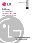
Disassembly Instructions
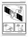
Equipment needed: Vacuum pump, Charging cylinder, Manifold gauge, Brazing equipment. Pinch-off tool capable of making a vapor-proof seal, Leak detector, Tubing cutter, Hand Tools to remove components, Service valve.
COMPOUND GAUGE
CONDENSER
(HIGH PRESSURE SIDE)
MANIFOLD
GAUGE
A
B
CAPILLARY TUBE
SEE INSETS
BELOW
EVAPORATOR
(LOW PRESSURE SIDE)
COMPRESSOR
LOW
HI
A
B
B
A
EXTERNAL
VACUUM PUMP
CHARGING
CYLINDER
C
FIG. 17A-Pulling Vacuum
FIG 17B-Charging
Service Manual 15
Schematic Diagram
Schematic Diagram
Wiring Diagram
■ ELECTRIC HEATING MODEL
16 Room Air Conditioner
Troubleshooting Guide
Troubleshooting Guide
Piping System
CONDENSER COILS
FAN
CAPILLARY TUBE
MOTOR
COMPRESSOR
TURBO FAN
EVAPORATOR COILS
: REFRIGERANT FLOW
Following is a brief description of the important components and their functions in the refrigeration system.
Refer to Fig. 18 to follow the refrigeration cycle and the flow of the refrigerant in the cooling cycle.
ROOM AIR CONDITIONER
CYCLE OF REFRIGERATION
EVAPORATOR COILS
CONDENSER COILS
COMPLETE LIQUID
BOIL OFF POINT
COOLED
AIR
SUCTION LIME
COOL LOW PRESSURE VAPOR
VAPOR INLET
HOT
DISCHARGED
AIR
ROOM AIR HEAT LOAD
OUTSIDE COOLING
AIR FOR REFRIGERANT
PASS THROUGH
MOTOR
COMPRESSOR
OIL
LIQUID
PRESSURE
DROP
LIQUID OUTLET
(LIQUID REFRIGERANT)
HIGH PRESSURE VAPOR
LIQUID PEFRIGERANT
CAPILLARY TUBE
LOW PRESSURE VAPOR
FIG. 18
Service Manual 17
Troubleshooting Guide
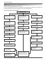
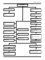
Troubleshooting Guide
In general, possible trouble is classified in two causes.
The one is called Starting Failure which is caused from an electrical defect, and the other is Ineffective Air
Conditioning caused by a defect in the refrigeration circuit and improper application.
Unit is running but cooling is ineffective
Ineffective Cooling
Check of cold air circulation
for smooth flow.
Check of outdoor coil
(heat exchanger) & the fan
operation.
Dirty indoor coil
(Heat exchanger)
Check gas leakage.
Malfunction of fan
Repair gas leak.
Clogged of air filter
Replacement of unit if the
unit is beyond repair.
Check heat load increase.
Unexpected residue
Overloaded Circuit
Check of inside gas
pressure.
Obstruction at air outlet
Adjusting of refrigerant
charge
Stop of auto air-swing
Malfunction of compressor
Correct above trouble
Replacement of
compressor
Check clogging in
refrigeration circuit.
Repair clogging in
refrigeration circuit.
18 Room Air Conditioner
Satisfactory operation with
temperature difference of
inlet & outlet air ; 44.6~50˚F
Troubleshooting Guide
Fails to Start
Check of power source.
Check of circuit breaker
and fuse.
Check of control switch
setting.
Gas leakage of feeler bulb
of thermostat
Check of control switch.
Only compressor fails to
start.
Only fan fails to start.
Improper wiring.
Drop of power voltage.
Improper thermostat setting
Defect of fan motor
capacitor.
Defect of compressor
capacitor.
Loose terminal connection.
Check capacitor.
Irregular motor resistance
( ).
Irregular motor insulation
( ).
Improper wiring
Replacement.
Replacement of fan motor
Irregular motor resistance ( )
Regular but fails to start
Irregular motor insulation ( )
Replacement of compressor
(locking of rotor, metal)
Replacement of compressor
(Motor damaged)
Service Manual 19
Troubleshooting Guide
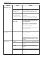
COMPLAINT
Fan motor will not run.
CAUSE
REMEDY
No power
Check voltage at outlet. Correct if none.
Wire disconnected or
connection loose
Connect wire. Refer to wiring diagram for terminal
identification. Repair or replace loose terminal.
Capacitor (Discharge
capacitor before testing.)
Test capacitor.
Replace if not within ±10% of manufacturer's
rating. Replace if shorted, open, or damaged.
Will not rotate
Fan blade hitting shroud or blower wheel hitting
scroll. Realign assembly.
Units using slinger ring condenser fans must
have 1/4 to 5/16 inch clearance to the base. If it is
hitting the base, shim up the bottom of the fan
motor with mounting screw(s).
Check fan motor bearings; if motor shaft will not
rotate, replace the motor.
Fan motor runs
intermittently
Revolves on overload.
Check voltage. See limits on this page. If not within
limits, call an electrician.
Test capacitor.
Check bearings. Does the fan blade rotate freely?
If not, replace fan motor.
Pay attention to any change from high speed to
low speed. If the speed does not change, replace
the motor.
Fan motor noise.
Grommets
Check grommets; if worn or missing, replace them.
Fan
If cracked, out of balance, or partially missing,
replace it.
Turbo fan
If cracked, out of balance, or partially missing,
replace it.
Loose set screw
Tighten it.
Worn bearings
If knocking sounds continue when running or
loose, replace the motor. If the motor hums or
noise appears to be internal while running,
replace motor.
20 Room Air Conditioner
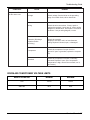
Troubleshooting Guide
COMPLAINT
Compressor will not run,
but fan motor runs.
CAUSE
REMEDY
Voltage
Check voltage. See the limits on the preceding.
page. If not within limits, call an electrician.
Wiring
Check the wire connections, if loose, repair or
replace the terminal. If wires are off, refer to wiring
diagram for identification, and replace. Check wire
locations. If not per wiring diagram, correct.
Capacitor (Discharge
capacitor before
servicing.)
Check the capacitor.
Replace if not within ±10% of manufacturers
rating. Replace if shorted, open, or damaged.
Compressor
Check the compressor for open circuit or
ground. If open or grounded, replace the compressor.
Overload
Check the compressor overload, if externally
mounted. Replace if open. (If the compressor
temperature is high, remove the overload, cool it,
and retest.)
ROOM AIR CONDITIONER VOLTAGE LIMITS
NAME PLATE RATING
MINIMUM
MAXIMUM
115V
103.5V
126.5V
208/230V
187V
253V
Service Manual 21
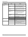
Troubleshooting Guide
COMPLAINT
Compressor cycles
on overload.
Insufficient cooling or heating
Excessive noise.
CAUSE
REMEDY
Voltage
Check the voltage. See the limits on the preceding page. If not within limits, call an electrician.
Overload
Check overload, if externally mounted.
Replace if open. (If the compressor temperature
is high, remove the overload, cool, and retest.)
Fan motor
If not running, determine the cause. Replace if
required.
Condenser air flow
restriction
Remove the cabinet. inspect the interior surface
of the condenser; if restricted, clean carefully
with a vacuum cleaner (do not damage fins) or
brush. Clean the interior base before
reassembling.
Condenser fins
(damaged)
If condenser fins are closed over a large area
on the coil surface, head pressures will increase,
causing the compressor to cycle. Straighten the
fins or replace the coil.
Test capacitor.
Check the terminals. If loose, repair or replace.
Check the system for a restriction.
If restricted, clean of replace.
Close if open.
Determine if the unit is properly sized for the area to
be cooled.
Check the set screw or clamp. If loose or missing,
correct. If the blower or fan is hitting air guide,
rearrange the air handling parts.
Remove the cabinet and carefully rearrange tubing
not to contact cabinet, compressor, shroud, and barrier.
Capacitor
Wiring
Refrigerating system
Air filter
Exhaust damper door
Unit undersized
Blower or fan
Copper tubing
22 Room Air Conditioner
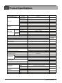
Product Specifications
ITEMS
MODELS
COOLING
HEATING
REMARK
POWER SUPPLY
1Ø,115V,60HZ
CAPACITY(Btu/h)
8,000
INPUT(W)
830
RUNNING CURRENT(A)
7.5
E.E.R(Btu/W.h)
9.6
CAPACITY(Btu/h)
3,850
INPUT(W)
1,230
RUNNING CURRENT(A)
OPERATING
TEMPERATURE
COOLING
HEATING
REFRIGERANT(R410A)
UE08C13
10.7
INDOOR(°F)
80 (DB) 67 (WB)
OUTDOOR(°F)
95 (DB) 75 (WB)
INDOOR(°F)
70 (DB) 60 ( WB)
OUTDOOR(°F)
47 (DB) 44 ( WB)
CHARGE(g)
320 (11.3OZ)
EVAPORATOR
2 ROW 12 STACKS
CONDENSER
Ø5.0 3 ROW 18 STACKS,L-BENDED TYPE
TURBO FAN
FAN,INDOOR
PROPELLER TYPE FAN WITH SLINGER-RING
FAN,OUTDOOR
FAN,SPEEDS (FAN/COOLING/HEATING)
2/2/2
6 POLES
FAN,MOTOR
OPERATION CONTROL
TOUCH PANEL
ROOM TEMP.CONTROL
THERMISTOR
VERTICAL LOUVER (RIGHT&LEFT)
AIR DIRECTTION CONTROL
HORIZONTAL LOUVER (UP&DOWN)
TOP - DOWN
CONSTRUCTION
3.5KW,230V
ELECTRIC HEATER
PROTECTOR
LOUVERFIN TYPE
COMPRESSOR
EXTERNAL OVERLOAD PROTECTOR
FAN,MOTOR
INTERANL THERMAL PROTECTOR
ELECTRIC HEATER
FUSE LINK,BIMETAL THERMOSTAT
1.92m(3WIRE WITH GROUDING)
POWER CORD
ATTACHMENT PLUG(CORD-CONNECTED TYPE)
DRAIN SYSTEM
SPLASHED BY FAN SLINGER
80/36
NET WEIGHT(lbs/kg)
DIMENSION
(Wx Hx D)
( inch)
( mm)
24 21/32 x 14 13/32 x 19 21/32
SLEEVE DIMESION
(Wx Hx D)
( inch)
( mm)
25 7/8 x 15 17/32 x 16 23/32
SLEEVE DEPTH
( inch)
( mm)
WITH FRONT GRILLE
656 x 366 x 499
656 x 394 x 425
OPTIONA PART
20
510
Service Manual 23
Product Specifications
ITEMS
MODELS
REMARK
POWER SUPPLY
COOLING
HEATING
COOLING
HEATING
REFRIGERANT(R410A)
1Ø,230/208V,60HZ
CAPACITY(Btu/h)
10 000/9 800
INPUT(W)
1,080/1 040
RUNNING CURRENT(A)
4.7/5.2
E.E.R(Btu/W.h)
9.4/9.4
CAPACITY(Btu/h)
11 200/9 200
INPUT(W)
3,500/2 900
RUNNING CURRENT(A)
OPERATING
TEMPERATURE
UE10C33
INDOOR(°F)
15.3/14.0
80 (DB) 67 (WB)
OUTDOOR(°F)
95 (DB) 75 (WB)
INDOOR(°F)
70 (DB) 60 ( WB)
OUTDOOR(°F)
47 (DB) 44 ( WB)
CHARGE(g)
440 (15.5OZ)
3 ROW 12 STACKS
EVAPORATOR
2 ROW 18 STACKS,L-BENDED TYPE 1 ROW
CONDENSER
TURBO FAN
FAN,INDOOR
PROPELLER TYPE FAN WITH SLINGER-RING
FAN,OUTDOOR
FAN,SPEEDS (FAN/COOLING/HEATING)
2/2/2
6 POLES
FAN,MOTOR
OPERATION CONTROL
TOUCH PANEL
ROOM TEMP.CONTROL
THERMISTOR
VERTICAL LOUVER (RIGHT&LEFT)
AIR DIRECTTION CONTROL
HORIZONTAL LOUVER (UP&DOWN)
TOP - DOWN
CONSTRUCTION
3.5KW,230V
ELECTRIC HEATER
PROTECTOR
LOUVERFIN TYPE
COMPRESSOR
EXTERNAL OVERLOAD PROTECTOR
FAN,MOTOR
INTERANL THERMAL PROTECTOR
ELECTRIC HEATER
FUSE LINK,BIMETAL THERMOSTAT
1.92m(3WIRE WITH GROUDING)
POWER CORD
ATTACHMENT PLUG(CORD-CONNECTED TYPE)
DRAIN SYSTEM
SPLASHED BY FAN SLINGER
80/36
NET WEIGHT(lbs/kg)
DIMENSION
(Wx Hx D)
( inch)
( mm)
24 21/32 x 14 13/32 x 19 21/32
SLEEVE DIMESION
(Wx Hx D)
( inch)
( mm)
25 7/8 x 15 17/32 x 16 23/32
SLEEVE DEPTH
( inch)
( mm)
WITH FRONT GRILLE
24 Room Air Conditioner
656 x 366 x 499
656 x 394 x 425
20
510
OPTIONA PART
Product Specifications
ITEMS
MODELS
REMARK
POWER SUPPLY
COOLING
HEATING
COOLING
HEATING
REFRIGERANT(R410A)
1Ø,230/208V,60HZ
CAPACITY(Btu/h)
11 500/11,200
INPUT(W)
1,220/1 190
RUNNING CURRENT(A)
5.6/6.0
E.E.R(Btu/W.h)
9.4/9.4
CAPACITY(Btu/h)
11 200/9 200
INPUT(W)
3,500/2 900
RUNNING CURRENT(A)
OPERATING
TEMPERATURE
UE12C13
INDOOR(°F)
15.3/14.0
80 (DB) 67 (WB)
OUTDOOR(°F)
95 (DB) 75 (WB)
INDOOR(°F)
70 (DB) 60 ( WB)
OUTDOOR(°F)
47 (DB) 44 ( WB)
CHARGE(g)
540 (19.0OZ)
3 ROW 12 STACKS
EVAPORATOR
2 ROW 18 STACKS,L-BENDED TYPE 1 ROW
CONDENSER
TURBO FAN
FAN,INDOOR
PROPELLER TYPE FAN WITH SLINGER-RING
FAN,OUTDOOR
FAN,SPEEDS (FAN/COOLING/HEATING)
2/2/2
6 POLES
FAN,MOTOR
OPERATION CONTROL
TOUCH PANEL
ROOM TEMP.CONTROL
THERMISTOR
VERTICAL LOUVER (RIGHT&LEFT)
AIR DIRECTTION CONTROL
HORIZONTAL LOUVER (UP&DOWN)
TOP - DOWN
CONSTRUCTION
3.5KW,230V
ELECTRIC HEATER
PROTECTOR
LOUVERFIN TYPE
COMPRESSOR
EXTERNAL OVERLOAD PROTECTOR
FAN,MOTOR
INTERANL THERMAL PROTECTOR
ELECTRIC HEATER
FUSE LINK,BIMETAL THERMOSTAT
1.92m(3WIRE WITH GROUDING)
POWER CORD
ATTACHMENT PLUG(CORD-CONNECTED TYPE)
DRAIN SYSTEM
SPLASHED BY FAN SLINGER
80/36
NET WEIGHT(lbs/kg)
DIMENSION
(Wx Hx D)
( inch)
( mm)
24 21/32 x 14 13/32 x 19 21/32
SLEEVE DIMESION
(Wx Hx D)
( inch)
( mm)
25 7/8 x 15 17/32 x 16 23/32
SLEEVE DEPTH
( inch)
( mm)
WITH FRONT GRILLE
656 x 366 x 499
656 x 394 x 425
OPTIONA PART
20
510
Service Manual 25
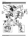
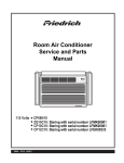
Exploded View
Exploded View
C
135312
147582-1
130900
145200
147581
147582-2
435300
152302
132100
135313
731273
D
352380
559011
349001
349480
148000
W48602
E
753000
149980
346811
130410
359012
349600
W48602
552206
A
567480
268711-2
238310
249950
267110
249940
268711-1
B
Co
ol
Energ
Savery
Fan
F1
F2 LOW
F3 MED
HIGH
Tim
MO
DE
567502
'F
er
TIM
ER
TE
MP
FA
SP N
EE
D
PO
WER
237200
264110
W0CZZ
26 Room Air Conditioner
550140
435301
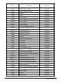
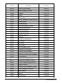
LocNo
Description
UE08C13
W0CZZ
CAPACITOR,FILM,BOX
67301909
130410
BASE ASSEMBLY,SINGLE
67302923
130900
CABINET
67303718
132100
FRAME
67303504
135303
GRILLE,INLET
67306113
135312
GRILLE ASSEMBLY,FRONT(SINGLE)
67306020
238310
ESCUTCHEON
67304802
W48602
CLAMP,SPRING
67302500
346811
MOTOR ASSEMBLY,SINGLE
67303019
147581
LOUVER,HORIZONTAL
67306203
147582-1
LOUVER,VERTICAL
67306252
147582-2
LOUVER,VERTICAL
67306253
349600
BRACKET,MOTOR
67303607
149980
SHROUD
67303111
550140
DAMPER,COMPRESSOR
67305000
152302
FILTER,AIR
67304304
352380
AIR GUIDE
67302735
359012
FAN,TURBO
67302608
559011
FAN ASSEMBLY,AXIAL
67303202
567480
THERMISTOR ASSEMBLY
67307808
264110
POWER CORD ASSEMBLY
67300031
267110
REMOTE CONTROLLER ASSEMBLY
67302239
567502
OverloadProtect
67301907
268711-2
PWB(PCB) ASSEMBLY,MAIN
67307644
268711-1
PWB(PCB) ASSEMBLY,DISPLAY
67307646
435300
PLASTIC REAR AIR DEFLECTOR
67307208
237200
PANEL,CONTROL
67305527
731273
INSTALL PART ASSEMBLY,SINGLE
67306307
249950
CASE ASSEMBLY,CONTROL
67305528
435301
GRILLE,REAR
67304801
349480
ORIFICE
67303406
753000
Heater,Electric
67310101
Service Manual 27
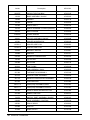
LocNo
Description
UE10C33
W0CZZ
CAPACITOR,FILM,BOX
67301910
130410
BASE ASSEMBLY,SINGLE
67302923
130900
CABINET
67303718
132100
FRAME
67303504
135303
GRILLE,INLET
67306104
135312
GRILLE ASSEMBLY,FRONT(SINGLE)
67306005
238310
ESCUTCHEON
67304802
W48602
CLAMP,SPRING
67302500
346811
MOTOR ASSEMBLY,SINGLE
67303008
147581
LOUVER,HORIZONTAL
67306203
147582-1
LOUVER,VERTICAL
67306252
147582-2
LOUVER,VERTICAL
67306253
349600
BRACKET,MOTOR
67303607
149980
SHROUD
67303111
550140
DAMPER,COMPRESSOR
67305000
152302
FILTER,AIR
67304304
352380
AIR GUIDE
67302735
359012
FAN,TURBO
67302608
559011
FAN ASSEMBLY,AXIAL
67303202
567480
THERMISTOR ASSEMBLY
67307808
264110
POWER CORD ASSEMBLY
67300029
267110
REMOTE CONTROLLER ASSEMBLY
67302239
567502
OverloadProtect
67301908
268711-2
PWB(PCB) ASSEMBLY,MAIN
67307645
268711-1
PWB(PCB) ASSEMBLY,DISPLAY
67307646
435300
PLASTIC REAR AIR DEFLECTOR
67307208
237200
PANEL,CONTROL
67305527
731273
INSTALL PART ASSEMBLY,SINGLE
67306307
249950
CASE ASSEMBLY,CONTROL
67305529
435301
GRILLE,REAR
67304801
349480
ORIFICE
67303406
753000
Heater,Electric
67310100
28 Room Air Conditioner
LocNo
Description
UE12C33
W0CZZ
CAPACITOR,FILM,BOX
67301911
130410
BASE ASSEMBLY,SINGLE
67302930
130900
CABINET
67303718
132100
FRAME
67303504
135303
GRILLE,INLET
67306104
135312
GRILLE ASSEMBLY,FRONT(SINGLE)
67306005
238310
ESCUTCHEON
67304802
W48602
CLAMP,SPRING
67302500
346811
MOTOR ASSEMBLY,SINGLE
67303020
147581
LOUVER,HORIZONTAL
67306203
147582-1
LOUVER,VERTICAL
67306252
147582-2
LOUVER,VERTICAL
67306253
349600
BRACKET,MOTOR
67303606
149980
SHROUD
67303111
550140
DAMPER,COMPRESSOR
67305000
152302
FILTER,AIR
67304304
352380
AIR GUIDE
67302735
359012
FAN,TURBO
67302608
559011
FAN ASSEMBLY,AXIAL
67303202
567480
THERMISTOR ASSEMBLY
67307808
264110
POWER CORD ASSEMBLY
67300029
267110
REMOTE CONTROLLER ASSEMBLY
67302239
567502
OverloadProtect
67301906
268711-2
PWB(PCB) ASSEMBLY,MAIN
67307645
268711-1
PWB(PCB) ASSEMBLY,DISPLAY
67307646
435300
PLASTIC REAR AIR DEFLECTOR
67307208
237200
PANEL,CONTROL
67305527
731273
INSTALL PART ASSEMBLY,SINGLE
67306307
249950
CASE ASSEMBLY,CONTROL
67305530
435301
GRILLE,REAR
67304801
349480
ORIFICE
67303406
753000
Heater,Electric
67310100
Service Manual 29
FRIEDRICH AIR CONDITIONING CO.
Visit our web site at www.friedrich.com
Post Office Box 1540 • 4200 N. Pan Am Expressway • San Antonio, Texas 78295-1540
• (210) 357-4400 • FAX (210) 357-4480
Printed in the U.S.A
Unifit Heat Cool Svc Parts 2010 (05/10)