1
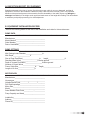
OWNERS MANUAL
INSTALLATION • OPERATION • MAINTENANCE
6” & 8” SUBMERSIBLE TURBINE PUMPS
BE SURE TO READ OWNER’S MANUAL
CAREFULLY BEFORE INSTALLING YOUR PUMP.
6” & 8” SUBMERSIBLE TURBINE PUMPS
CONTENTS
Inspection-Receipt of Equipment....................................................... Sec. A
Equipment and Installation Record................................................. Sec. B
General Information........................................................................ Sec. C
Suitability of the Well...................................................................... Sec. D
Installation-Site & Support Equipment............................................ Sec. E
Electrical Installation....................................................................... Sec. F
Pump Installation............................................................................ Sec. G
Accessories with Installation........................................................... Sec. H
Operational Checkup...................................................................... Sec. I
Troubleshooting.............................................................................. Sec. J
1
A. INSPECTION-RECEIPT OF EQUIPMENT
Examine equipment at the time of receipt. Check that the power cable is not cut or damaged, and that all
equipment is correct for the installation. Handle the pump, cable and motor carefully. This is very important
because of the precise alignment of the assembly and the vulnerability of the cable. Report any damages or
shortages immediately to the freight carrier agent and make notes on the freight bill of lading. This will facilitate
a satisfactory and prompt processing of a claim adjustment.
B. EQUIPMENT INSTALLATION RECORD
*Record the following details at the time of the installation and retain for future references:
PUMP DATA________________________________________________________
Manufacturer____________________________________________
Model Number___________________________________________
Serial Number____________________________________________
Date of Installation________________________________________
PUMP SETTINGS____________________________________________________
Well Casing Inside Diameter_________________in.
Well Depth_________________ft.
length_________________ft.
Size of Drop Pipe(Riser)_________________in.
Standing Water Level_________________ft. below ground
Depth to Lowest Perforation_________________ft.below ground
Number of Check Valves_________________
Power Cable Size_________________in.
length_________________ft.
Length of Air Line_________________ft.
MOTOR DATA______________________________________________________
Maunfacturer____________________________________________
Horsepower______________________________________________
Voltage/Phase/Cycle________/_________/_____________________
Full Load Amperage______________________________________
Motor Size______________________________________________
Model__________________________________________________
Serial Number-Date Code__________-________________________
Pump Capacity and Head___________________________________
Installed by______________________________________________
Address_________________________________________________
Phone No_______________________________________________
2
C. GENERAL INFORMATION
The Submersible pump unit comprises a vertical Turbine
pump assembly directly-coupled to a Submersible electric
motor. The connecting bracket accommodates the
coupling between the pump and motor shafts and also
serves as the water intake passage.
The pump unit is suspended in the well by the riser
pipe, and the electric power is taken down from the well
head to the motor by the Submersible cable which is
secured at intervals to the riser pipe.
Please read the manufactures separate instruction
manual for the motor, and keep it for future reference.
D. SUITABILITY OF THE WELL
Submersible Pumps as well as all water pumps, are
designed to handle clean, cool, clear water. Water from
an undeveloped well often contains excessive amounts of
sand, dirt and other abrasives which can cause damage
to the pump.
Install the pump in a well which has already
been properly developed with a test pump.
The test pump also provides a means to determine
the capacity and setting of the pump to the yield
of the well. If the pump removes water at a higher
rate than the well produces, the drawdown will be
excessive and this will cause the pump to cavitate,
resulting in damge to the pump or motor.
The well must be deep enough so that the pump
suction is at least 10 ft. below the expected
drawdown level.
The insider diameter of the well casing must be large
enough to allow lowering the unit into the well without
damage to the “Power Cable”, and the splice between
the power cable and the Motor leads. Check that the
well is large enough to allow installation of the pump
at the required depth. Keep the pump atleast 5 ft.
from the bottom, particularly where there is a history
of sand in the well. Do not install the pump below the
lowest perforations in the well casing unless the well
size permits the installation of a shroud over unit to
ensure an adequate flow of water over the motor for
cooling purposes.
The Motor must always be immersed in flowing water.
E. INSTALLATIONSITE & SUPPORT EQUIPMENT
Equipment & Material Required;
The material and equipment necessary for the installation
of the pump will vary with the pump size and type of
installation. The following list of tools and supplies are
offered as a guide.
-Materials; Anti-galling lubricant, thread compound,
lubricating oil, grease.
-Tools & Instruments; Tripod with chain blocks, or rig
with power hoist, pipe clamps, megger, pipe wrenches,
and mechanical tools.
Be sure that the equipment is strong enough to lift the
total weight of the pump, riser pipe and water in the
riser pipes.
When the Power Cable is supplied on a reel, support
the reel on a piece of pipe laid across a pair of sturdy saw
horses. Locate the reel about six feet from the well so that
the cable unwinds from the top.
FOUNDATION
Construct a concrete foundation which must be RIGID,
LEVEL and of adequate STRENGTH to support the
complete weight of the pump, motor, column, plus the
weight of the water pumping through it without exceeding
the permissible bearing pressure for the subsoil.
Support the riser pipe at the well head with a well seal,
surface plate, or other adapter which seals the well in
accordance with local regulations. Make provision for a
conduit to carry the power cable into the well.
RISER PIPE
Make up the riser pipe from random lenghts of threaded
and coupled pipe, and make arrangements to secure it
at the well by a well seal, surface plate, or other adapter.
Use schedule 40 steel pipe for settings less than 600 ft.
For deeper settings, use schedule 40 for the bottom 600
ft., and for the remainder use schedule 80.
Take great care to keep pipes clean and free from
pebbles, scale, and thread chips. Tighten each joint
securely. Make sound, airtight connections at all fittings.
CHECK VALVES
*CAUTION*
DO NOT INSTALL THE UNIT WITH THE MOTOR
RESTING ON THE BOTTOM, OR CLOSER THAN
FIVE FEET FROM THE BOTTOM OF THE WELL.
If the pump setting exceeds 100 ft., install a check valve
at the first joint in the riser pipe above the pump.
For a deep setting pump, a line checkvalve is
recommended for every 200 ft. of column pipe. Always
use an additional check valve at the surface if the pump
is part of a pressure system or if the pressure head
exceeds 500 ft.
3
Method #2- Resin Cast Splice
*CAUTION*
TAKE CARE TO PREVENT DAMAGE TO THE
CABLE DURING THE INSTALLATION.
F. ELECTRICAL INSTALLATION
When the cable is supplied on a reel, support the reel on
a piece of pipe laid across a pair of sturdy saw horses.
Locate the reel about 6 ft. from the well so that the cable
unwinds from the top.
Prevent the cable from scraping on the well casing
and avoid pinching the cable either in the pipe clamps or
between the riser pipe and well casing.
SPLICING POWER CABLE TO MOTOR LEADS
A waterproof splice must be made to connect the power
cable to the motor leads. An improperly made splice will
become a service problem. There are different materials
and methods that are used to make water tight
cable splices.
-Examples; by waterproof TAPE splice, RESIN CAST
splice, or by HEAT SHRINK splice.
Method #1- Taped Splice
1- Remove 10 in. from the outer jackets of the jacketed
cable, taking care not to damage the insulation of the
individual conductors.
2- Trim the motor leads, so that the yellow wire is 3 in.
shorter and the black wire is 3 in. longer than the red one.
3- Trim the wires of the cable so that the yellow wire is 3
in. longer and the black wire is 3 in. shorter that the red one.
4- Strip 1/2 in. of insulation from the end of each wire and
scrape the metal clean and thoroughly clean the surface
with solvent to insure a watertight splice.
5- Join like-colored wires with connectors and secure
connectors with staking pliers. Pull on wires to make sure
the wires are firmly crimped.
Fill each connector with solder to insure sound
mechanical and electrical joints.
6- Bind each connection with approved self-bonding
rubber tape, with the first layer extending atleast 1 in. over
the insulation, and the second layer extending atleast 1
in. beyond the first. Apply two layers of plastic insulating
tape, each extending 1 in. beyond the previous one. Bind
the three connectors together with one lapyer of approved
self-bonding rubber tape, and two layers of approved
electrical tape, all extending over the outer sheath if a
Prepare the 3-conductor power cable for splicing, insert
a sharp knife blade between the cable jacket and lead
insulation and strip the jacket back 2.6” from the end.
Strip the cambric wrapping (if any) off of the conductors
and strip back rubber insulation 5/8” from the end.
Assemble the cable connectors and crimp them in place
using a crimping tool.
Cut off motor leads to equal length. Clean off ends of
the leads for about 12”, using a wet cloth with gasoline or
solvent. Clean the end of the power cable also. Insert the
three motor leads into corresponding holes in the bottom
of the rubber casing and push them several inches
out the top. Crimp the motor leads into corresponding
connectors, crimping the center one first. Bend the cables
into line with the holes in the csing up until the connectors
are inside the holes about 1/4” from the top.
Mix the resin as directed. Cut off a corner of the bag
and squeeze all of the resin into the casing. With the roll
of tape on hand, fold the bag, and tape the top of the bag
snugly to the power cable until the resin runs out over the
top.This will assure maximum coverage of the resin and
minimize the size of the finished splice. When the resin is
firm to the touch, the splice may be immersed for testing.
REPAIR
Although cuts and abrasions may not puncture the cable
insulation, repair them in the following manner.
Use a solvent such as paint thinner or gasoline to clean
the cable in the area of damage. Roughen the surface
of the insulation with sandpaper and apply a coating
of rubber cement to the prepared surface and let dry
for 1/2 hour. Cut off a length of 3/4” wide vinyl plastic
electrical tape 1” longer than the cut or abrasion, and lay
it smoothly over the damage. Start binding the cable with
the same tape 1” in front of the damage lapping each
wrap halfway over the previous one, until the binding
extends 1” beyond the damage.
Wind the tape smoothly without wrinkles and avoid
stretching it unduly. Add three more layers in a similar
manner, each extending 1/2” beyond that beneath.
Apply a coating of rubber cement over the repair as an
additional bond and to improve the resistance to
oil and solvents.
WARNING
GROUND THE UNIT WHEN TESTING, FAILURE
TO GROUND THE UNIT PROPERLY CAN RESULT
IN SERIOUS OR FATAL SHOCK.
4
ELECTRICAL INSTALLATION & TESTS
Employ a competent electrician to do the wiring in
accordance with local electrical codes. Conventional
overhead or underground installation is satisfactory for
the electrical power transmission to the Well Head.
Check that the power supply corresponds with that
shown on the name plates of the motor and control box.
NOTE; every installation requires a fused disconnect
switch or circuit breaker.
A SINGLE-PHASE unit includes a control box
incorporating overload relays, but require a magnetic
starter for automatic operation.
A THREE-PHASE unit requires a magnetic starter
with three-leg protection having QUICK-TRIP Ambient
compensated overload relays.
Note; the Warranty is void if incorrect overload relays
are used.
Mount the control equipment vertically on a post or
wall, and protect it from direct sunlight and extremes
of temperature. Make the connections to the control
equipment in accordance with the wiring diagram to avoid
damage to the motor.
Preliminary Electrical Test Pump Above Ground
After splicing the motor leads to the power cable, use a
500-volt megohm meter (megger) to test the insulation.
Connect the ground lead of the megger to the motor
frame, and the line leads to the ends of the cable
conductors. Turn the crank of the megger for 5 or 10
seconds, and check that the needle shows a value of at
least 50 megohms. Remove the megger and wet down
the motor leads and power cable with a hose or bucket.
Reconnect the megger and check the resistance again.
Should the value be appreciably less than before, it
indicates damaged insulation. Locate the damage either
by visual inspection or by checking the resistance as
each successive section of cable are immersed in water.
If the cable is new, it is probably unnecessary to check it
thoroughly from above the splice down to the motor.
G. PUMP INSTALLATION-PERFORMANCE
Should the cable get damaged, either cut out the defective
length and splice the ends, or repair the damage, as
described in the section on cable Repair(F).
INSTALLATION
Thread the first length of riser pipe into the pump
discharge and raise the pump and pipe into a vertical
position over the well. Being careful neither to drag the
pump along the ground, nor let it strike other objects
getting it into place over the well.
Lower the pump about 10 ft. into the well and fasten the
cable to the riser pipe to prevent tangling and damage.
Use electrical tape for light cable and stainless steel
bands for heavy cable.
Continue to add lengths in the same manner until the
required pump setting is reached. Secure the cable to the
riser pipe at regular intervals with tape or bands.
*CAUTION*
TAKE GREAT CARE TO PREVENT DAMAGE TO
THE CABLE DURING INSTALLATION.
Use an Ohmmeter or megger to make continuity and
insulation checks on the cable at intervals of 10 to 20 ft.
as the pump is lowered. This will locate any fault in
the cable.
Where a bleeder type air charging kit is used with a
hydro pneumatic tank, install the tee and bleeder valve
before adding the last length of riser pipe. This will place
the bleeder valve about 20 ft. below the well head.
Place the sanitary well seal, surface plate. Or other
adapter on the last length of riser pipe and pass the
submersible cable through the opening provided. Then
attach the discharge tee or elbow to the riser pipe. Lower
the riser pipe to its final position and tighten the well seal
or other device to support the installation in the well.
As soon as the splice joint is submerged in the water,
take a resistance reading between the power cable
conductors and ground to assure that the insulation
and the cable or the splice was not damaged during
installation process.
Initial Start-up & Performance Check
Make final continuity and insulation (0 megohms or
higher) checks before connecting the cable to the control
equipment. Check that the supply voltage is within10% of
the motor rating. It is preferable for the supply voltage to
be on the high side. Check all phases of a
three-phase supply.
Check the pump and well performance before making
the final connection to the discharge system.
1- Install a pressure gage and gate valve on the end of
the pipe. Close the valve.
2- Start the pump, check the pressure developed against
the closed valve. If the pressure is substantially less than
expected (don’t forget to allow for the depth to the water
level), the pump may be running backward. To change the
ratation, refer to the section “Preliminary Electrical Test
Pump Above Ground”.
3- Open the gate valve to give a low flow until you are
certain that the well will not yield sand. Open the gate
valve gradually to give full flow.
4- Use a hook-on ammeter to read the current, which
should approximate the full-load current given on the
motor nameplate, but must not exceed the service factor
rating of the motor. The service factor varies with the
make and the horsepower of the motor. Consult the
factory if insufficient information is given about Service
Factor performance.
5
Check that the currents in the individual phases of
a 3-phase system are approximately equal. Where
there is considerable difference between them, change
all 3 connections at the starter as shown below (so
that rotation remains the same) to obtain the most
consistent readings.
Starter
L1
L2
L3
cable (1)
cable (2)
cable (3)
black
red
yellow
yellow
black
red
red
yellow
black
Then subtract the average of the readings from the
highest. The difference, expressed as a percent of the
average must not exceed 10%. Note that the highest
reading must not exceed the maximum permissible
for the motor.
EXAMPLE:
Phase 1
54.0 amp
Phase 2
55.0 amp
Phase 3
60.0 amp
Average: 56.3 amp
(a) Install additional riser pipe to place pump lower in
the well if possible.
(b) Use a cock or similar valve in the discharge line to
throttle the pump output to suit the yield of the well.
(c) Install FLOATLESS LIQUID LEVEL CONTROL.
(d) Use a pressure switch with a low water protection
or a separate low-water cutout switch. Neither of
these devices give as reliable protection as a floatless
liquid level control and both require careful application.
(e) Replace the pump with smaller unit to avoid over
pumping the well.
*CAUTION*
NEVER RUN THE PUMP UNLESS IT IS
COMPLETELY SUBMERGED IN WATER.
Damage can occur to both pump and motor, in addition,
air drawn into the pump can cause air-lock.
H. ACCESSORIES WITH INSTALLATION
LIGHTNING ARRESTERS
% Unbalance = 60 - 56.3 x 100
56.3
= 3.7 x 100 = 6.6%
56.3
WARNING
FAILURE TO GROUND THE UNIT PROPERLY CAN
RESULT IN SERIOUS OR FATAL SHOCK. REFER
TO ELECTRICAL CODE REQUIREMENTS.
Should the unbalance exceed 10%, ask the power
company to improve the voltage balance between the
incoming lines.
5- Use a voltmeter to check the voltage at the starter while
the pump is running. The average must be within 10% of
the motor rating, and the maximum variation of any phase
of a 3-phase system for the average should not
exceed 1%.
6- Continue to run the pump until the drawdown of the
water in the well becomes stable. Should the water level
drop to the pump intake to admit air, use one or more of
the following methods to protect installation.
Install lightning arresters to protect the motor from the
effects of electrical storms. Although they will not give
protection against direct stirkes they will ground the
surges caused in transmission lines by surrounding
storms.
One arrester is sufficient for a single-phase unit, but
two are necessary for a three-phase unit. Install them in
accordance with the manufacturers separate instructions,
either in the control box on some single-phase systems,
or in the supply line immediately ahead of the control
equipment. Pay particular attention to the ground
connection. DO NOT USE GROUND ROD. Use the best
ground on the premises, which is usually the metal riser
pipe from the pump or other metal water pipe.
RELIEF VALVE
Always install a relief valve if the pump is capable of
developing pressures in the discharge system greater
than the pressure ratings of individual components. The
relief valve must be large enough to handle the pump
output at the relief pressure.
6
FLOATLESS LIQUID LEVEL CONTROL
The sensing elements of a floatless liquid level control
consists of 2 electrodes suspended in the well by
insulated wires. These wires connect to a relay which
serves as a pilot switch to the starting equipment. The
lower electode is set just above the pump, and the upper
at some distance below the static water level. The device
cuts off power to the pump automatically when the water
level drops below the lower electrode, and does not
restore power until the water level recovers to reach the
upper electrode. The Liquid Level Control can also be
used as a pilot switch in connection with elevated tanks.
J. TROUBLESHOOTING
1. Disconnect power unless required for testing.
2. Have electrical testing done by a qualified electrician.
3. Most problems occur above ground. Remove pump
only as a last resort.
When troubleshooting or servicing the pump, use all
precautions for the voltages involved.
PROBLEM
POSSIBLE CAUSE
REMEDY
1. Electrical trouble
Check Power source:
starter & reset
I. OPERATIONAL CHECKUP
The most reliable indication of the condition of a
submersible pump are:
(a) The current drawn by the motor
(b) The insulation resistance of the installation
below ground.
As the pump wears, the motor current increases, until
eventually the overloads trip to protect the motor. While
this automatic protection looks after an emergency
situation, proper care of a submersible installation should
include perioodic check-ups to avoid interruptions in
the water supply. Use a megger to check the insulation
resistance every six months.
Record the insulation resistance and the running current
for future reference. When the insulation resistance
fall below 10 Megohms, check it frequently for further
deterioration and pull the pump when the resistance falls
to 1/2 megohm.
When pulling the pump, either coil the cable on a reel
or raise it from the ground to dry. Check the insulation
again when the cable and splices are dry. If the insulation
value is between the line and motor casing increases
to 50 megohms or more, isolate the fault in the cable or
the splice and make the necessary repairs. However, if
the insulation reading remains low, disconnect the motor
from the cable and check the motor separately. Should
the motor be defective, check the pump end for wear and
obtain a replacement for either the motor alone, or the
pump unit, as necessary.
WARNING
Check resistance:
cable and motor
Unit fails
to start
Pump fails
to deliver
water
Reduced
pump
output
Overload
trips
Unit cycles
too
frequently
Call Dealer or Electrician
2. Pump Sandlocked
Call Dealer: pull pump
and clean
1. Insufficient well yield:
water level has dropped.
Reset pump lower into well
2. Clogged intake screen
Pull pump
3. Air Lock in pump
Start and stop pump
several times and allow 1
min. between
4. Leak in discharge
Raise pipe until leak is found.
1. Screen or pump partly
plugged
Pull pump and clean
2. Insufficient well yield
Check water level: lower
pump if permissible.
3. Worn pump - excessive
wear due to abrasives.
Replace worn parts
4. Low voltage
Call Electrician
5. Three Phase unit
running backward
Reverse rotation
1. Worn pump or pump
bound by sand
Pull pump and clean or
replace worn parts.
2. Electrical trouble
Call Dealer or Electrician
1. Pressure switch out of
adjustment
Readjust to correct setting
or replace
Restrict flow to yield
2. Leaks in service line
Locate and correct
3. Check valve leaking
Replace
4. Water logged tank
Check tank for leaks be
sure fittings are functioning
properly.
HAZARDOUS VOLTAGE- CAN SHOCK, BURN,
OR EVEN KILL.
7
U.S. LIMITED WARRANTY*
Franklin Pump Systems, Inc.
Franklin Pump Systems, Inc. warrants its new products to be free of defects in material and
workmanship for a period of 1 year from date of installation or 2 years from date of manufacture,
whichever comes first, WHEN installed in a domestic water systems application and pumping potable
water only. Warranty does not cover applications pumping saltwater or other corrosive liquids. Consult
and adhere to local codes for all applications. Franklin Pump Systems, Inc. also provides additional
warranty coverage on specific products as specified herein.
Franklin Pump System’s warranty obligation with regard to equipment not of its own manufacture is
limited to the warranty actually extended to Franklin Pump System by its suppliers.
This warranty extends only to the original retail purchaser and only during the time in which the
original retail purchaser occupies the site where the product was originally installed.
Requests for service under this warranty shall be made by contacting the installing Franklin Pump
System dealer (point of purchase) as soon as possible after the discovery of any alleged defect.
Franklin Pump System will subsequently take corrective action as promptly as reasonably possible.
Franklin Pump System at its discretion may replace or repair any product that fails under this
warranty after inspection by an authorized company representative or after Franklin Pump System has
received the product at our factory. Replacement or repair cannot be made until after the product is
inspected. All charges or expenses for freight to and from the factory, removal and reinstallation of the
product, or installation of a replacement product are the responsibility of the purchaser.
THIS WARRANTY SUPERSEDES ANY WARRANTY NOT DATED OR BEARING AN EARLIER
DATE. ANY IMPLIED WARRANTIES WHICH THE PURCHASER MAY HAVE, INCLUDING
MERCHANT ABILITY AND FITNESS FOR A PARTICULAR PURPOSE, SHALL NOT EXTEND
BEYOND THE APPLICABLE WARRANTY PERIOD. Some states do not allow limitations on
how long an implied warranty lasts, so the above limitation may not apply to you. IN NO
EVENT SHALL FRANKLIN PUMP SYSTEM BE LIABLE FOR INCIDENTAL OR CONSEQUENTIAL
DAMAGES. Some states do not allow the exclusion or limitation of incidental or consequential
damages, so the above may not apply to you.
This warranty does not apply to any product which has been subjected to negligence, alteration,
accident, abuse, misuse, improper installation, vandalism, civil disturbances, or acts of God. The only
warranties authorized by Franklin Pump System are those set forth herein. Franklin Pump System
does not authorize other persons to extend any warranties with respect to its products, nor will Franklin
Pump System assume liability for any unauthorized warranties made in connection with the sale of its
products.
THIS WARRANTY GIVES YOU SPECIFIC LEGAL RIGHTS, AND YOU MAY ALSO HAVE
OTHERRIGHTS WHICH MAY VARY FROM STATE TO STATE.
* Contact Franklin Pump Systems, Inc. Export Division for International Warranty.
12401 Interstate 30 • P.O. Box 8903
Little Rock, AR 72219
12401 Interstate 30 • P.O. Box 8903
Little Rock, AR 72219
E-631
5/05