1
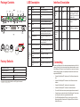
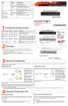
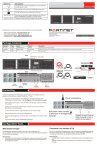
QuickStart Guide
Configuring
Web-based Manager
Use the following procedure to connect to the web-based manager for the first time.
Configuration changes made with the web-based manager are effective immediately without resetting the FortiBridge unit or interrupting service.
To connect to the web-based manager
1. Connect the management port of the FortiBridge unit to Ethernet port of the management computer.
Use a cross-over Ethernet cable to connect the devices directly. Use straight-through
Ethernet cables to connect the devices through a hub or switch.
2. Configure the management computer to be on the same subnet as the FortiBridge
management port interface.
To do this, change the IP address of the management computer to 192.168.1.2 and
the netmask to 255.255.255.0.
3. To access the FortiBridge web-based manager, in your browser, go to
http://192.168.1.99.
4. Type admin in the Name field and click Login.
To configure Probes
Probes monitor the FortiGate unit by sending packets from the INT 2 interface through
the FortiGate unit to the EXT 2 interface. If probe packets are not received at the EXT 2
interface the FortiBridge unit detects a failure.
Configure probe settings to set actions on failure, add a dynamic IP pattern used by the
probe packets, and enter the serial number of the FortiGate unit. Actions on failure can
include failing open and sending an alert email, a syslog message, and an SNMP trap.
1.
2.
3.
4.
5.
Go to Probe > Settings.
Enter the Probe IP address pattern (#.#.#.*).
Enable ping, HTTP, FTP, POP3, SMTP, and/or IMAP probes.
Set the Port Number for each protocol.
Change the Failure Threshold and probe Interval for each probe.
To set up Notifications
1. Go to Probe > Notifications.
2. Enter a Notification Message Tag.
3. Optionally, select the Syslog check box and enter the IP address, port and facility of
the Syslog server that receives FortiBridge syslog messages.
4. Optionally, select the Email check box and enter the SMTP server, email addresses,
SMTP user name, and password of the users to send the alert email.
5. Optionally, select the SNMP check box and enter the name, hosts, and traps of the
SNMP manager to send alerts to a community.
3.
computer. Use these settings: Baud Rate 9600, Data bits 8, Parity None, Stop bits 1,
Flow Control None.
At the login: prompt, type admin and press Enter twice.
(The login prompt is preceded by the server default host name.)
To configure the FortiBridge unit using the CLI
1. Change the management IP address.
config system manageip
set ip <intf_ip>/<netmask_ip>
end
2.
Configure the primary and secondary DNS server IP addresses.
config system dns
set primary <dns-server_ip>
set secondary <dns-server_ip>
end
3.
Configure the default gateway.
config system route
edit 1
set gateway <gateway_ip>
end
4.
Change the administrator password.
config system admin
edit admin
set password <password>
end
Shutting down the FortiBridge unit
FortiBridge-2002
INT1
FortiBridge 2002
CONSOLE1
MODEM1
MGMT1
INT3
EXT1
CONSOLE2
EXT1
INT1
HA1
USB1
BYPASS1
MODE1
INT2
INT2
FortiGate
EXT2
EXT2
PWR1
RESET1
MODEM2
MGMT2
EXT3
EXT3
INT3
USB2
INT4
FortiGate
EXT4
EXT4
AC Power
50 W, 100 - 240 VAC, 50 - 60Hz
Chassis
1U
Dimensions
HA2
BYPASS2
PWR2
NORMAL2
MODE2
INT4
NORMAL1
RESET2
44.0 cm x 30.1 cm x 4.44 cm
8 10/100/1000 Ingress/Egress ports
Network Interfaces
2 10/100/1000 Management ports
2 USB connections
2 Console
When powering off the FortiBridge unit, always shut down the unit using the following procedures before disconnecting the power supply. Not following this procedure can increase
the risk of damaging the FortiBridge flash disk.
To power off the FortiBridge unit
1. Go to System > Status.
2. In the Unit Operation area, click Shut Down.
3. Once the indicates the shut down procedure has completed, disconnect the
FortiBridge unit from the power source.
To configure the Management, Default Gateway, and Primary and Secondary DNS server
IP addresses
1. Go to System > Status > Management Port area and click Change.
Command Line Interface
To connect to the FortiBridge unit
1. Use a RJ-45 to DB-9 cable to connect the FortiBridge management port to the management computer serial port.
2. Start a terminal emulation program (such as HyperTerminal) on the management
Visit these links for more information and documentation for your Fortinet product:
Technical Documentation - http://docs.fortinet.com Fortinet Knowledge Center - http://kb.fortinet.com
Technical Support - http://support.fortinet.com Training Services - http://campus.training.fortinet.com
© Copyright 2010 Fortinet Incorporated. All rights reserved.
Products mentioned in this document are trademarks or registered trademarks
of their respective holders.
Regulatory Compliance
FCC Class A Part 15, UL/CB/CUL, C Tick, VCCI
28 May 2010
01-410-124725-20100510
Package Contents
LED Description
LED
EXT1 and
EXT2
INT1 and
INT2
EXT3 and
EXT4
INT3 and
INT4
Reset1
Reset2
Mode2
Mode1
INT1
FortiBridge 2002
MODEM1
CONSOLE1
MGMT1
INT3
EXT1
CONSOLE2
EXT1
INT1
USB1
HA1
BYPASS1
PWR1
NORMAL1
MODE1
INT2
FortiGate
EXT2
INT2
Modem1
USB1
Console1 Management1
EXT2
LEDs
LEDs
MODEM2
MGMT2
Normal
EXT3
EXT3
INT3
USB2
RESET1
HA2
BYPASS2
PWR2
NORMAL2
MODE2
INT4
FortiGate
EXT4
INT4
Modem2
USB2
Console2 Management2
DISCONNECT TWO POWER SUPPLY CORDS
BEFORE SERVICING
Ground
Power
EXT4
LEDs
RESET2
HA
LEDs
State
Description
Green
The unit is powered on.
Off
The unit is powered off.
Green
The unit is being used in Normal
mode.
Green
The unit is being used in a HA cluster.
Off
The unit is in stand-alone mode.
Green
Bypass network activity at this interface.
Off
Normal status.
Green
The correct cable is in use and the
connected equipment has power.
Green flashing
Network data is being sent or received.
Off
No link established or the interface
has been turned off.
Link/Activity (left) Green
Port has power and network connection.
Link/Activity (left) Green
flashing
Network data is being sent or received.
Speed (right) indicator is
Green
Connected at 1000 Mbps.
Speed (right) indicator is
Amber
The interface is connected at 100
Mbps.
Speed (right) indicator
is Off
The interface is connected at 10
Mbps.
Bypass
DISCONNECT TWO POWER SUPPLY CORDS
BEFORE SERVICING
Power button
Power button
AC power
connection
AC power
connection
INT and
EXT LEDs
QuickStart Guide
FortiGate-30B
INT1
FortiBridge 2002
CONSOLE1
MODEM1
MGMT1
INT3
EXT1
CONSOLE2
EXT1
INT1
USB1
HA1
BYPASS1
PWR1
NORMAL1
MODE1
INT2
INT2
FortiGate
EXT2
EXT2
RESET1
MODEM2
MGMT2
EXT3
EXT3
INT3
USB2
HA2
BYPASS2
PWR2
NORMAL2
MODE2
INT4
FortiGate
EXT4
INT4
EXT4
RESET2
Tools and Documenation
Power cable x2
Copyright 2010 Fortinet Incorporated. All rights reserved.
Trademarks
Products mentioned in this document are trademarks.
Straight-through
Ethernet cable
DB9-RJ45 Serial
cable
Factory Defaults
Administrator user name
admin
Administrator password
(none)
NAT/Route mode
Management1
192.168.1.99
Management2
0.0.0.0
To reset the unit to the factory defaults, in the CLI type the command:
execute factoryreset
REGISTER
INT,
EXT, and
MANAGEMENT
Ports
Interface Description
Interface
Type
Speed
Protocol
Description
Console1
and Console2
RJ-45
9600 bps
8/N/1
RS-232
serial
Connection to the management computer. Provides
access to the command line
interface (CLI).
Modem1
and Modem2
RJ-11
USB1 and
USB2
USB
Management1 and
Management2
RJ-45
INT1, INT2,
INT3, INT4,
EXT1,
EXT2,
EXT3,
EXT4
RJ-45
Phone line for internal
modem.
USB
Two optional connections to
a USB key for installation.
10/100/1000
Base-T
Ethernet
Two management ports.
10/100/1000
Base-T
Ethernet
Ingress and Egress ports.
Connecting
Connect the FortiBridge unit to the internal and external networks and the FortiGate unit. Normally, you would use straight-through ethernet cables to connect
the FortiBridge unit. However, for some connections you may need a crossover
ethernet cable (for example, for compatibility with network devices that do not
support Auto MDI/MDIX).
•
Connect the FortiBridge INT 2 interface to the FortiGate unit internal interface.
•
Connect the FortiBridge EXT 2 interface to the FortiGate unit external
interface.
•
Connect the FortiBridge INT 1 interface to the internal network.
•
Connect the FortiBridge EXT 1 interface to the external network.
•
Turn on the FortiGate unit and any network equipment that was turned off.
•
Connect the power cords at the back of the FortiBridge unit. Plug the other
end of the power cables into a grounded electrical outlet.
•
The PWR and Bypass Mode LEDs turn on. After a short time, the FortiBridge unit switches to Normal mode. The Bypass LED turns off and the
Normal LED turns on.