1
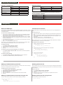
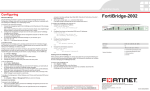
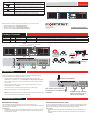
Light Icon
QuickStart Guide
Description
The light flashes orange when packets are sent and received on
the Ethernet port 1 and 2.
FortiManager-3000B
Power indicator is blue when the FortiManager system is on.
The light flashes blue when reading the boot device.
Hard Disk Upper LED
Blue when the hard disk is properly inserted into the drive bay
and the FortiManager is plugged in to a power source.
Hard Disk Lower LED
Flashes blue when reading and writing to the hard disk.
PS RST
2
DISK DRIVE LEGEND
HDD 1 (P0)
1
POWER
ACTIVITY
HDD 4 (P3)
HDD 2 (P1)
HDD 5 (P4)
HDD 3 (P2)
HDD 6 (P5)
Visit these links for more information and documentation for your Fortinet product.
•
•
•
•
© Copyright 2009 Fortinet Incorporated. All rights reserved.
Products mentioned in this document are trademarks or registered trademarks
of their respective holders.
Regulatory Compliance
FCC Class B Part 15 CSA/CUS
11 March 2010
Technical Documentation - http://docs.fortinet.com
Fortinet Knowledge Center - http://kb.fortinet.com
Fortinet Technical Support - http://support.fortinet.com
Training Services - http://campus.training.fortinet.com
02-40000-112745-20091027
Package Contents
Connector
Type
Speed
Protocol
Description
Port 1 to 4
RJ-45
100/1000 Base-T
Ethernet
Connection to the internal network.
CONSOLE
DB9
9600 bps 8/N/1
RS-232 serial
Optional connection to the management computer. Provides access to the command line interface.
USB
USB
USB
For future use.
Front
LED Indicators
Power Button
Power Suppy Alarm Reset Button
®
PS RST
QuickStart Guide
2
FortiManager-3000B
1
PS RST
DISK DRIVE LEGEND
2
POWER
ACTIVITY
DISK DRIVE LEGEND
Back
HDD 1 (P0)
HDD 2 (P1)
HDD 3 (P2)
HDD 4 (P3)
EMPTY
EMPTY
Straight-through
and cross over
Ethernet cables
USB (Behind front panel)
DB9 Serial
connection
USB for
future use
Ethernet
connections
HDD 3 (P2)
HDD 4 (P3)
1
POWER
ACTIVITY
Tools and Documenation
Copyright 2008 Fortinet Incorporated. All rights reserved.
Trademarks
Products mentioned in this document are trademarks.
DB-9 Serial Cable
REGISTER
4 hot-swappable
hard disks
Power Cables
Power
connections
HDD 1 (P0)
HDD 2 (P1)
Ethernet
connections
Connecting
Connect the following to the FortiManager system. Ensure the FortiManager system is
placed on a stable surface or securely mounted in a 19” rack.
•
Insert the hard disks included in the FortiManager package into the bays of the
FortiManager unit, starting in bay 1. Use the diagram on the front panel as a guide.
•
Insert a network cable to port 1. Insert the other end to the router or switch connected
to the network.
•
Connect one power chord to a power supply. Connect the other power cord to an
alternate power source if available.
•
Connect the Power Cord to a surge protected power bar or power supply.
•
Press the Power button to turn on the FortiManager unit.
•
The power LED appears blue and the hard disk icon LED flashes blue while the system
boots.
•
•
Power connections
Null modem cable connects
to serial port on management
computer.
For more information, see the FortiManager Install Guide.
Straight-through Ethernet
cable connects to hub or
switch on the network.
Configuration Tools
Web-based manager
Command Line Interface (CLI)
The FortiManager web-based manager is an easy to use management tool.
Use it to configure the administrator password, the interface and default gateway addresses,
and the DNS server addresses.
The CLI is a full-featured management tool. Use it to configure the administrator password,
the interface addresses, the default gateway address, and the DNS server addresses. To
configure advanced settings, see the Tools and Documentation CD-ROM.
Requirements:
• An Ethernet connection between the FortiManager system and management computer.
• A web browser such as FireFox 2.0 and higher or Internet Explorer 6.0 and higher on
the management computer.
Requirements:
• The DB9 serial connection between the FortiManager system and management computer.
• A terminal emulation application (HyperTerminal for Windows) on the management
computer.
Collecting Information
General settings
Interface configuration
IP:
____.____.____.____
admin
____.____.____.____
Administrative account
settings
User name
Netmask:
Password
(none)
Port 2 Interface:
IP:
____.____.____.____
Network Settings
Default Gateway:
____.____.____.____
Netmask:
____.____.____.____
Primary DNS Server:
____.____.____.____
Port 3 Interface:
IP:
____.____.____.____
Secondary DNS Server:
____.____.____.____
Netmask:
____.____.____.____
IP:
____.____.____.____
Netmask:
____.____.____.____
Port 1 Interface:
Port 4 interface:
The interface IP address and netmask must be valid for the internal network.
A default gateway is required for the FortiGate unit to route connections to the Internet.
Factory default settings
Port 1 interface
192.168.1.99
Port 2 interface
0.0.0.0
Port 3 interface
0.0.0.0
DHCP server on Internal interface 0.0.0.0
To reset the FortiGate unit to the factory defaults, in the CLI type the command
execute factory reset
Configuring
Web-based Manager
Command Line Interface
Use the following procedure to connect to the web-based manager for the first time. Configuration changes made with the Web Config are effective immediately without resetting the unit
or interrupting service.
The unit has serial port. Use the null modem cable to connect it to your management computer.
To connect to the web-based manager
1. Connect the Port 1 interface of the unit to Ethernet port of the management computer.
Use a cross-over Ethernet cable to connect the devices directly. Use straight-through
Ethernet cables to connect the devices through a hub or switch.
2. Configure the management computer to be on the same subnet as the Port 1 interface.
To do this, change the IP address of the management computer to 192.168.1.2 and the
netmask to 255.255.255.0.
3. To access the web-based manager, in your browser, go to https://192.168.1.99 (remember to include the “s” in https://).
4. Type admin in the Name field and select Login.
After connecting to the Web-based manager, you can configure the unit IP address, DNS
server IP address, and default gateway to connect the unit to the network.
To configure interfaces
1.
2.
3.
4.
Go to System Settings > Network > Interface.
Click the edit icon to configure each interface.
Set the IP address and netmask for the interface.
Click OK.
To configure the Primary and Secondary DNS server IP addresses
1. Go to System Settings > Network > DNS, enter the Primary and Secondary DNS IP
addresses click Apply.
To connect to the unit
1. Use a null modem cable to connect the serial port to the management computer serial
port.
2. Start a terminal emulation program (such as HyperTerminal) on the management computer. Use these settings: Baud Rate 9600, Data bits 8, Parity None, Stop bits 1, Flow
Control None.
3. At the login: prompt, type admin and press Enter twice.
(The login prompt is preceded by the server default host name.)
After connecting to the CLI, you can configure the unit IP address, DNS server IP address,
and default gateway to connect the unit to the network.
To configure the unit using the CLI
1. Set the IP address and netmask of the Port1 interface.
config fmsystem interface
edit port1
set ip <intf_ip>/<netmask_ip>
end
3. Configure the primary and secondary DNS server IP addresses.
config fmsystem dns
set primary <dns-server_ip>
set secondary <dns-server_ip>
end
1. Go to System Settings > Network > Static Routing and select Create New.
2. Set Gateway to the Default Gateway IP address and click OK.
4. Configure the default gateway.
config fmsystem route
edit 1
set device <interface>
set dst <destination_ip>
set gateway <gateway_ip>
end
Adding an administration password
Shutting down the unit
By default, the admin user does not have a password. To restrict access to the unit management account, add password for the admin user account.
When powering off the unit, always shut down the unit using the following procedures before
disconnecting the power supply. Not following this procedure can increase the risk of damaging the hard disk.
To configure a Default Gateway
To add the admin user account password
1.
2.
3.
4.
5.
6.
Go to System Settings > Administration > Administrator.
Select the admin user name to edit the profile.
Select the Change Password checkbox.
Enter the old password.
Enter a new password in the New Password and Confirm Password fields.
Click OK.
Adding an administration password using the CLI
To add an administration password in the CLI enter the following commands:
config fmsystem admin user
edit admin
set password
please input password value <password>
To power off the unit
1.
2.
3.
4.
Go to System Settings> General > Dashboard.
In the System Operation list, select Shut Down.
Click Go.
Once the indicates the shut down procedure has completed, disconnect the
unit from the power source.
Shutting down the unit using the CLI
Enter the following command at the prompt:
execute shutdown