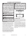
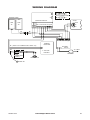
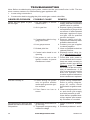
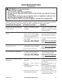
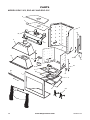
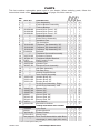
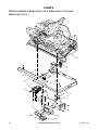
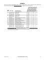
1
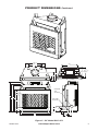
MASONRY RADIANT GAS FIREPLACE
WITH ELECTRONIC IGNITION
OWNER’S OPERATION AND INSTALLATION MANUAL
FIREBOX MODELS
BVC-36Y, BVC-42Y and BVC-50Y
Natural Gas Module models
BBM-36N-TKA, BBM-42N-TKA AND
BBM-50N-TKA
PROPANE/LP MODULE models
BBM-36P-TKA, BBM-42P-TKA AND
BBM-50P-TKA
Split Brick Panels with
bricks series mbk-36,42,50(SS)
(SH)-(R)I)
PFS
®
US
WARNING: If the information in these instructions
is not followed exactly, a fire or explosion may result
causing property damage, personal injury or death.
FOR YOUR SAFETY
— Do not store or use gasoline or any other flammable
vapors or liquids in the vicinity of this or any other
appliance.
— WHAT TO DO IF YOU SMELL GAS :
• Do not try to light any appliance.
• Do not touch any electrical switch;
• Do not use any phone in your building.
• Immediately call your gas supplier from a neighbor’s
phone. Follow the gas supplier’s instructions.
• If you cannot reach your gas supplier, call the fire
department.
— Installation and service must be performed by a qualified installer, service agency or the gas supplier.
INSTALLER: Leave this manual with the appliance.
CONSUMER: Retain this manual for future reference.
For more information, visit www.fmiproducts.com
WARNING: Improper installation, adjustment, alteration, service or maintenance can cause injury or
property damage. Refer to this manual for correct installation and operational procedures. For assistance
or additional information consult a qualified installer,
service agency or the gas supplier.
NOT FOR USE WITH SOLID FUEL
CHECK LOCAL CODES PRIOR TO INSTALLATION
SAVE THIS BOOK
This book is valuable. In addition to instructing you on
how to install and maintain your appliance, it also contains information that will enable you to obtain replacement parts or optional accessory items when needed.
Keep it with your other important papers.
State of Massachusetts: The installation must be made
by a licensed plumber or gas fitter in the Commonwealth
of Massachusetts.
TABLE OF CONTENTS
Safety................................................................... 3
Unpacking............................................................ 4
Introduction........................................................... 5
Selecting Location................................................ 6
Specifications....................................................... 6
Product Dimensions............................................. 7
Preinstallation Preparation................................. 10
Venting Installation............................................. 12
Installation.......................................................... 17
Operation............................................................ 31
2
Cleaning and Maintenance................................. 33
Replacement Parts............................................. 34
Service Hints...................................................... 34
Technical Service............................................... 34
Accessories........................................................ 34
Wiring Diagram................................................... 35
Troubleshooting.................................................. 36
Parts................................................................... 38
Warranty...............................................Back Cover
www.fmiproducts.com
122280-01E
Safety
WARNING: This product contains and/or generates chemicals
known to the State of California
to cause cancer or birth defects
or other reproductive harm.
IMPORTANT: Read this owner’s
manual carefully and completely
before trying to assemble, operate or service this fireplace.
Improper use of this fireplace
can cause serious injury or death
from burns, fire, explosions,
electrical shock and carbon
monoxide poisoning.
DANGER: Carbon monoxide
poisoning may lead to death!
This fireplace is a vented product. This fireplace
will not produce any gas leakage into your home
if properly installed. This fireplace must be
properly installed by a qualified service person.
If this unit is not properly installed by a qualified
service person, gas leakage can occur.
Carbon Monoxide Poisoning: Early signs of
carbon monoxide poisoning resemble the flu,
with headaches, dizziness or nausea. If you
have these signs, the fireplace may not have
been installed properly. Get fresh air at once!
Have fireplace inspected and serviced by a
qualified service person. Some people are more
affected by carbon monoxide than others. These
include pregnant women, people with heart or
lung disease or anemia, those under the influence of alcohol and those at high altitudes.
Propane/LP gas and natural gas are both
odorless. An odor-making agent is added
to each of these gases. The odor helps you
detect a gas leak. However, the odor added
to these gases can fade. Gas may be present
even though no odor exists.
Make certain you read and understand all
warnings. Keep this manual for reference. It
is your guide to safe and proper operation of
this fireplace.
1. This appliance is only for use with the type
of gas indicated on the rating plate. This
appliance is not convertible for use with
other gases unless a certified kit is used.
2. For propane/LP fireplace, do not place
propane/LP supply tank(s) inside any
structure. Locate propane/LP supply
tank(s) outdoors. To prevent performance
problems, do not use propane/LP fuel tank
of less than 100 lbs. capacity.
3. If you smell gas
•shut off gas supply
•do not try to light any appliance
•do not touch any electrical switch; do not
use any phone in your building
•immediately call your gas supplier from
a neighbor’s phone. Follow the gas
supplier's instructions
•if you cannot reach you gas supplier, call
the fire department.
4. Never install the fireplace
•in a recreational vehicle
•in high traffic areas
•in windy or drafty areas
5. This fireplace reaches high temperatures.
Keep children and adults away from hot
surfaces to avoid burns or clothing ignition. Fireplace will remain hot for a time
after shutdown. Allow surfaces to cool
before touching.
6. Carefully supervise young children when
they are in the room with fireplace.
7. A hearth extension is not required with this
appliance. If one is installed, it is for aesthetic purposes only and does not have
to meet the standard requirements.
8. Turn fireplace off and let cool before servicing or repairing. Only a qualified service
person should install, service or repair
this fireplace. Have fireplace inspected
annually by a qualified service person.
9. You must keep control compartments,
burners and circulating air passages clean.
More frequent cleaning may be needed due
to excessive lint and dust from carpeting,
bedding material, etc. Turn off the gas valve
and pilot light before cleaning fireplace.
10.Have venting system inspected annually by
a qualified service person. If needed, have
venting system cleaned or repaired.
WARNING: Any change to
this fireplace or its controls can
be dangerous.
122280-01E
www.fmiproducts.com
3
Safety
Continued
11.Keep the area around your fireplace clear
of combustible materials, gasoline and
other flammable vapor and liquids. Do
not run fireplace where these are used or
stored. Do not place items such as clothing
or decorations on or around fireplace.
12.Do not use this fireplace to cook food or
burn paper or other objects.
13.Do not use any solid fuels (wood, coal,
paper, cardboard, etc.) in this fireplace.
Use only the gas type indicated on fireplace nameplate.
14.This appliance, when installed, must be
electrically grounded in accordance with
local codes or, in the absence of local
codes, with the National Electrical Code,
ANSI/NFPA 70.
15.Do not obstruct the flow of combustion
and ventilation air in any way. Provide
adequate clearances around air open-
ings into the combustion chamber along
with adequate accessibility clearance for
servicing and proper operation.
16.Do not install fireplace directly on carpeting, vinyl tile or any combustible material
other than wood. The fireplace must set
on a metal or wood panel extending the
full width and depth of the fireplace.
17.Do not use fireplace if any part has been
exposed to or under water. Immediately
call a qualified service person to arrange
for replacement of the unit.
18.Do not operate fireplace if any log is
broken.
19.Do not use a blower insert, heat exchanger insert or other accessory not approved
for use with this fireplace.
20.Provide adequate clearances around air
openings.
Unpacking
CAUTION: Do not remove
data plates from module. Data
plates contain important warranty and safety information.
Note: Unit and all its loose components are
attached to carton tray inside box.
1. Remove entire contents of box using tray
handles (see Figure 1).
2. Set tray on floor and remove floor media
components and remote control.
3. Remove module with log set from tray by
cutting zip ties. Discard tray and foam.
4. Check all items for any shipping damage.
If damaged, promptly inform dealer where
you bought appliance.
4
Carton Tray
with Handles
Figure 1 - Log Set in Packing Box
www.fmiproducts.com
122280-01E
Introduction
Models BBM-36(N,P)-TKA, BBM-42(N,P)TKA and BBM-50(N,P)-TKA are vented gas
appliances that use an electronic control
valve and electronic ignition system. A FMI
PRODUCTS, LLC venting system and vent
cap are not supplied but are required for
proper operation If a B-type venting system
is installed, transition pipe model BTC-B is
required. See venting instructions beginning
on page 12.
WARNING: This gas appliance must not be connected to
a chimney flue servicing a solid
fuel burning appliance.
BEFORE YOU BEGIN
Before beginning the installation of your
appliance, read these instructions through
completely.
This FMI PRODUCTS, LLC appliance and
its approved components are safe when
installed according to this installation manual
and are operated as recommended by FMI
PRODUCTS, LLC. Unless you use FMI
PRODUCTS, LLC approved components
tested for this appliance, YOU MAY CAUSE
A FIRE HAZARD!
The FMI PRODUCTS, LLC warranty will
be voided by and FMI PRODUCTS, LLC
disclaims any responsibility for the following
actions:
A) Modification of the appliance or any of the
components.
B) Use of any component part not approved
by FMI PRODUCTS, LLC in combination
with this appliance.
C) Installation and/or operation in a manner
other than instructed in this manual.
D) The burning of anything other than the
type of gas approved for use in this gas
appliance.
The installation must conform with local
codes or, in the absence of local codes, with
the current National Fuel Gas Code, ANSI
Z223.1/NFPA 54.
122280-01E
WARNING: Installation of this
appliance should be done by a
qualified service person.
NOTICE: This appliance is not
intended to be used as a primary
source of heat.
CAUTION: Do not connect
appliance before pressure testing gas piping. Damage to gas
valve may result and an unsafe
condition may be caused.
The appliance and it’s individual shutoff valve
must be disconnected from the gas supply
piping system during any pressure testing of
that system at test pressures in excess of 1/2
psig (3.5 kPa).
The appliance must be isolated from the gas
supply piping system by closing its individual
manual shutoff valve during any pressure
testing of the gas supply piping system at
test pressures equal to or less than 1/2 psig
(3.5 kPa).
For the purpose of input adjustment two
pressure taps (for IN and OUT pressures)
are provided on the gas control valve for test
gauge connections to the appliance.
www.fmiproducts.com
5
Selecting Location
To determine the safest and most efficient
location for your appliance, you must take into
consideration the following guidelines:
1. The location must allow for proper clearances (see clearance information on
page 10).
2. Consider a location where heat output
would not be affected by drafts, air conditioning ducts, windows or doors.
3. A location that avoids the cutting of joists
or roof rafters will make installation easier.
Figure 1 shows a plan view of a few common locations.
Flush installations are recommended where
living space is limited or at a premium and
since the space required to enclose the appliance would be located beyond an outside
wall, this would also reduce the cutting of
joists, roof rafters and such. Check local
codes for any restrictions.
Projected installations can extend any
distance into the room. A projection may
be ideal for a new addition on an existing,
finished wall.
Corner installations make use of space
that may not normally be used and provides
a wider and more efficient range for radiant
heat transference.
Internal wall installations provide a discreet
option for room separation and can also be
ideal as an addition to an existing wall.
INTERNAL WALL
INSTALLATION
FULL
PROJECTION
INSTALLATION
CORNER
INSTALLATION
FLUSH
INSTALLATION
Figure 2 - Possible Locations for
Installing Appliance
Specifications
GAS RATING - NATURAL
BBM-36N-TKA
BBM-42N-TKA
BBM-50N-TKA
Max. Input Rating:
52,000 Btu/Hr
56,000 Btu/Hr
60,000 Btu/Hr
Manifold Pressure:
3.5" WC (.87 kPa)
3.5" WC (.87 kPa)
3.5" WC (.87 kPa)
Min. Supply Pressure: 4.5" WC (1.12 kPa) 5.0" WC (1.24 kPa) 5.0" WC (1.24 kPa)
Max. Supply Pressure: 10.5" WC (2.66 kPa) 10.5" WC (2.66 kPa) 10.5" WC (2.66 kPa)
Orifice Size:
# 26
# 23
# 18
GAS RATING - PROPANE/LP
BBM-36P-TKA
BBM-42P-TKA
BBM-50P-TKA
Max. Input Rating:
46,000 Btu/Hr
52,000 Btu/Hr
57,000 Btu/Hr
Manifold Pressure:
10" WC (2.49 kPa)
10" WC (2.49 kPa)
10" WC (2.49 kPa)
Min. Supply Pressure:
11" WC (2.74 kPa)
11" WC (2.74 kPa)
11" WC (2.74 kPa)
Max. Supply Pressure: 13" WC (3.23 kPa)
13" WC (3.23 kPa)
13" WC (3.23 kPa)
Orifice Size:
# 46
# 44
# 43
*For the purpose of input adjustment.
6
www.fmiproducts.com
122280-01E
Product Dimensions
29"
22 1/2"
14 1/2"
22"
18 3/8"
19 13/16"
(Ref.)
26 5/8"
15 5/8"
35 3/8"
4 /2"
1
1 5/16"
36" HEARTH
11"
OUTSIDE AIR
ACCESS
67"
61"
49"
58"
30"
GAS LINE
ACCESS
7"
1"
1"
36"
45 1/8"
10 1/2" 9 1/2"
3 1/2"
4 1/2"
7 1/4"
11"
15 1/4"
Figure 3 - 36" Model BVC-36Y
122280-01E
www.fmiproducts.com
7
Product Dimensions Continued
30 1/2"
22 3/4"
15 3/4"
25"
22 1/2"
23 13/16"
(Ref.)
29"
17 /8"
5
4 3/8"
41 3/8"
1 5/16"
42" HEARTH
5/8"
OUTSIDE
AIR
ACCESS
11"
67" 58"
61"
49"
30"
GAS LINE
ACCESS
10 1/2" 9 1/2"
3 1/2"
7"
1"
42"
51 1/8"
4 1/2"
81/2"
13"
17"
Figure 4 - 42" Model BVC-42Y
8
www.fmiproducts.com
122280-01E
Product Dimensions Continued
38 1/2"
24"
19 1/4"
33"
23 13/16"
221/2" (Ref.)
28 1/2"
17 5/8"
49 3/8"
50" HEARTH
43/8"
OUTSIDE
AIR
ACCESS
11"
67"
61"
58"
49"
GAS LINE
ACCESS
30"
10 1/2"
7"
1"
1 5/16"
50"
59"
9 1/2"
3 1/2"
4 1/2"
8 1/2"
13"
17"
Figure 5 - 50" Model BVC-50Y
122280-01E
www.fmiproducts.com
9
Preinstallation Preparation
selecting location
To determine the safest and most efficient
location for the fireplace, you must take into
consideration the following guidelines:
1. The location must allow for proper
clearances (see Figures 6 and 7).
2. Consider a location where fireplace will
not be affected by drafts, air conditioning
ducts, windows or doors.
3. A location that avoids cutting of joists or
roof rafters will make installation easier.
4. An outside air kit is available with this
fireplace (see Optional Outside Air Kit,
page 11).
fabricated to fit your required platform
height. Ember protector should extend
under fireplace a minimum of 1 1/2". Ember
protector should be made of galvanized
sheet metal (28 gauge minimum to prevent corrosion.
67 1/8"
58 1/8"
Minimum clearance to
combustibles
Back and sides of fireplace
1 1/2" min.*
Front of fireplace
48" min.
Floor**
0" min.
Perpendicular wall to opening
12" min.
Top spacers
0" min.
Mantel clearances
see Mantels, page 11
Chimney outer pipe surface
1" min.
59 1/4" (50")
51 1/4" (42")
45 1/4" (36")
* Not required at nailing flanges
** See step 2 of Framing
WARNING: Do not pack required air spaces with insulation
or other materials.
Framing
1. Frame opening for fireplace using dimensions shown in Figures 6 and 7.
2. If fireplace is to be installed directly on
carpeting, tile (other than ceramic) or any
combustible material other than wood
flooring, fireplace must be installed upon
a metal or wood panel extending full width
and depth of fireplace.
3. Set fireplace directly in front of this opening and slide unit back until nailing flanges
touch side framing.
4. Check level of the fireplace and shim with
sheet metal if necessary.
5. Before securing fireplace to prepared
framing, ember protector (provided) must
be placed between hearth extension (not
supplied) and under bottom front edge
of fireplace to protect against glowing
embers falling through. If fireplace is to
be installed on a raised platform, a Z-type
ember protector (not supplied) must be
10
30 1/8"
(42", 50")
28 1/4" (36")
Figure 6 - Rough Opening Dimensions
for Installing in a Wall
Maintain 1 1/2"
Clearance
at Sides and
Back of Fireplace
61" (36" Models)
65" (42" Models)
71" (50" Models)
1 1/2" Clearance
Not Required at
Nailing Flanges
86.5" (36" Models)
92" (42" Models)
100" (50" Models)
Figure 7 - Corner Installation
www.fmiproducts.com
122280-01E
PreInstallation Preparation
Continued
6. Using screws or nails, secure fireplace to
framing through flanges located on sides
of fireplace.
WARNING: When finishing
appliance, do not overlap combustible material onto the black
front face. Brick, tile or other
noncombustible materials may
be applied to the face provided
that any gap is between the
material used and the face is
caulked with a noncombustible
caulking.
The maximum height for the
air vent can not exceed 3 feet
below the flue gas outlet of the
termination.
MANTELs
A combustible mantle shelf maybe installed
a maximum 12" (22.9 cm) from the wall.
Figure 9 and Figure 10 on page 12 show
the minimum allowable distances from
various combustible mantle components
in relation to the fireplace opening.
Optional Outside air Kit
(Model AK4/AK4F)
Installation of an outside air kit should be
performed during rough framing of fireplace
due to the nature of it's location. Outside combustion air is accessed through a vented crawl
space (AK4F) or through a sidewall (AK4).
See Figure 39 on page 32 for instruction of
operating air kit.
CAUTION: Combustion air
inlet ducts shall not terminate
in attic space.
Secure to Collars with Metal Tape, Screws
or Straps (Min. of 1/4" x 20" in size)
Combustible
Materials
30°
12"
(22.9 cm)
6" (15.2 cm)
14"
8"
3" (7.6 cm)
1 1/2"
(3.8 cm) Max.
Figure 9 - Mantel Clearances - Side View
(Cross Section)
Air Inlet
Location
Must Allow
For Bushes
or Snow
Vented Crawl Space
(Check Local Codes
Before Installing in a
Vented Crawl Space)
Air Inlet
Eyebrow
Vent Hood
Required for
Wall Installation
Figure 8 - Outside Air Kit
122280-01E
www.fmiproducts.com
11
PreInstallation Preparation
Continued
TOP VIEW
Combustible
Material May
Be Used
Outer
Surround
1 1/2"
(3.8 cm)
Max.
3" (7.6 cm)
Max.
6" (15.2 cm)
Max.
SAFE
ZONE
33°
9"
(22.9 cm)
12"
(30.5 cm)
Perpendicular
Wall
Figure 10 - Side Clearances - Top View (Cross Section)
Venting Installation
A FMI PRODUCTS, LLC or an 8" B-type venting system must be connected to appliance for
venting to the outside of building. Transition
pipe model BTC-8 is required for use with
B-type venting.
Standing codes requirements concerning
vent installations may vary within your state,
province or local codes jurisdiction. Therefore,
it is recommended that you check with your
local building codes for specific requirements
or in absence of local codes, follow Section
7.0 of the current National Fuel Gas Code
ANSI Z223.1/NFPA 54.
This gas appliance must be vented to the
outdoors only and may not be terminated into
an attic space or into a chimney flue servicing
a solid-fuel burning appliance.
Lowest
Listed
Discharge Vent Cap
Opening
8 Ft. Min.
Listed
Gas
Vent
H (Min)
Height
From Roof
x
12
Roof Pitch x/12
Listed Clearance
Vent terminations must be located in accordance with height and proximity rules of
NFPA No. 54. These rules apply to vents at
12" diameter or less and require a minimum
height in accordance with the roof pitch and a
minimum of 8 ft. distance from a vertical wall
or obstruction (see Figure 11).
WARNING: This appliance
must be properly connected
to a system and must not be
connected to a chimney flue
servicing a separate solid fuel
burning appliance.
Roof Pitch
Flat to 6/12
6/12 to 7/12
Over 7/12 to 8/12
Over 8/12 to 9/12
Over 9/12 to 10/12
Over 10/12 to 11/12
Over 11/12 to 12/12
Over 12/12 to 14/12
Over 14/12 to 16/12
Over 16/12 to 18/12
Over 18/12 to 20/12
Over 20/12 to 21/12
H (Min.)
Feet
1.0
1.25
1.5
2.0
2.5
3.25
4.0
5.0
6.0
7.0
7.5
8.0
Meter
0.30
0.38
0.46
0.61
0.76
0.99
1.22
1.52
1.83
2.13
2.27
2.44
Figure 11 - Typical Terminations
12
www.fmiproducts.com
122280-01E
Venting INSTALLATION
Continued
EFFECTIVE HEIGHT
OF TERMINATION CAP
UP TO
6 FT. MAX.
12 FT.
MINIMUM
HEIGHT
17 FT.
MINIMUM
HEIGHT
3 FT. MINIMUM
TO OFFSET
Figure 12 - Typical Residential Installations
Venting Installation using FMI
PRODUCTS, LLC Venting System
FMI PRODUCTS, LLC chimney system
consists of 12", 18", 24", 36" and 48" snaplock, double-wall pipe segments, planned
for maximum adaptability to individual site
requirements.
WARNING: The opening in
collar around chimney at top of
fireplace must not be obstructed.
Never use blown insulation to fill
chimney enclosure.
12 3/8"
Galvanized
Outer Pipe
8" Stainless
Inner Pipe
Hemmed
End
PART NO.
DESCRIPTION
12-8DM
18-8DM
24-8DM
36-8DM
48-8DM
RT-8DM
RTL-8DM
Pipe Section
Pipe Section
Pipe Section
Pipe Section
Pipe Section
Round Termination
Round Termination
Round Termination with Slip
RTT-8DM
Section
Round Termination with Slip
RTTL-8DM
Section
ET-8DM
Square Chase-Top
ETO-8DM
Square Chase-Top with Mesh
Square Chase-Top with Slip
ETL-8DM
Section
Square Chase-Top with Mesh &
ETLO-8DM
Slip Section
60E-8DM
60° Offset and Return
Figure 13 - Chimney Pipes and Accessories
122280-01E
www.fmiproducts.com
13
Venting INSTALLATION
Continued
Assembly and installation of
double wall chimney system
Each double wall chimney section consists of
a galvanized outer pipe, a stainless steel inner flue pipe and a wire spacer. Pipe sections
must be assembled independently as chimney
is installed. When connecting chimney directly
to fireplace, inner flue pipe section must be
installed first with lanced side up. Outer pipe
section can then be installed over flue pipe
section with hemmed end up. Press down
on each pipe section until lances securely
engage hem on fireplace starter. The wire
will assure proper spacing between inner and
outer pipe sections.
Opening in collar around
chimney at top of fireplace must
not be obstructed. Never use
blown insulation to fill chimney
enclosure.
Continue to assemble chimney sections as
outlined, making sure that both inner and outer
pipe sections are locked together. When installing double wall snap-lock chimney together, it
is important to assure joint between chimney
sections is locked. Check by pulling chimney
upward after locking. Chimney will not come
apart if properly locked. It is not necessary to
add screws to keep chimney together.
Firestop Spacers (V3600FS-8DM)
Firestop spacers are required at each point
where chimney penetrates a floor space.
Their purpose is to establish and maintain
required clearance between chimney and
combustible materials. When pipe passes
through a framed opening into a living space
above, firestop must be placed onto ceiling
from below as shown in Figure 14.
If area above is a living space, install
firestop below framed hole.
Figure 14 - Firestop Spacer with Living
Space Above Ceiling
They also provide complete separation from
one floor space to another or attic space as
required by most codes. When double wall
pipe passes through a framed opening into
an attic space, firestop must be placed into
an attic floor as shown in Figure 15.
If area above is an attic or insulated area,
install firestop above framed hole.
Figure 15 - Firestop Spacer with Attic
Space Above Ceiling
14
www.fmiproducts.com
122280-01E
Venting Installation
Continued
Penetrating roof
To maintain a 1" clearance to pipe on a roof
with a pitch, a rectangular opening must
be cut.
1. Determine center point where pipe will
penetrate roof.
2. Determine center point of roof. Pitch is
the distance the roof drops over a given
span, usually 12". A 6/12 pitch means that
the roof drops 6" for each 12" measure
horizontally down from roof rafters.
3. Use roof opening chart (Figure 16) to
determine correct opening length and
flashing required.
4. Remove shingles around opening measured. Cut out this section.
Flashing installation (v6f-8dm
or v12f-8dm)
Determine flashing to be used with roof opening chart. Slide flashing over pipe until base is
flat against roof. Replace as many shingles as
needed to cover exposed area and flashing
base. Secure in position by nailing through
shingles (see Figure 17). DO NOT NAIL
THROUGH FLASHING CONE.
Storm Collar
Flashing
Cone
Nail Only
Outer
Perimeter
of Flashing
Overlap
Shingles Top
and Sides Only
Minimum Measurements
14 3/8"
(36.5 cm)
1"
(2.5
cm)
30"
(76.2 cm)
1"
(2.5 cm)
1"
(2.5
cm)
Opening "A"
Pitch
Slope
Flat
0-6/12
6/12- 12/12
0°
26.6°
45.0°
Opening Used Flashing
"A" Max.
Model No.
15"
V6F-8DM
16 1/8"
V6F-8DM
20 3/8"
V12F-8DM
Figure 16 - Roof Opening Measurements
Underlap Shingles
at Bottom
Figure 17 - Flashing Installation
Installing Flashing on a Metal Roof
When installing flashing on a metal roof, it
is required that putty tape be used between
flashing and roof. Flashing must be secured
to roof using #8 x 3/4" screws and then sealed
with roof coating to prevent leakage through
screw holes. A roof coating must also be applied around perimeter of flashing to provide
a proper seal.
Storm Collar Installation (SC1 or SC2)
Place storm collar over pipe and slide down
until it is snug against open edge of flashing
(see Figure 18). Use SC1 for all round terminations and SC2 for all terminations with
slip sections. Apply waterproof caulk around
perimeter of collar to provide a proper seal.
Chimney
Pipe
Waterproof
Caulk
Storm
Collar
Flashing
Figure 18 - Storm Collar
122280-01E
www.fmiproducts.com
15
Venting Installation
Continued
Terminations/Spark Arrestor
Fireplace system must be terminated with
listed round top or chase terminations. In any
case, refer to installation instructions supplied
with termination. Terminations approved for
this fireplace are RT-8DM and RTL-8DM that
can be used for flashing or chase and ET8DM, ETO-8DM, ETL-8DM and ETLO-8DM
for chase style termination only. Figure 19
shows an RTL-8DM round top termination.
CAUTION: Do not seal openings on the rooftop flashing. Follow the installation instructions
provided with the termination
being used.
Terminations with 16" slip pipe sections are
available. RTT-8DM and RTTL-8DM are
approved for flashing installations. When
needed, these adjustable terminations may
be used in combination with pipe assembly
to achieve correct chimney height.
Note: In rare instance there is a problem with
side driven rain or wind or chimney is not drafting properly, an ADS-8DM (Anti-Draft Shield)
can be used with round terminations.
Attach Bracket
Tabs to
Outer Pipe
(3 Places)
Secure with
Screws
Overlap
Shingles Top
and Sides
RTL-8D
Level of
Flue Gas
Outlet
Caulk
Collar
Flashing
Underlap Shingles
Bottom Only
Figure 19 - Termination
16
Venting installation using 8"
B-Type venting system
Transition pipe model BTC-8 and starter collar
are shown in Figure 20. Remove starter collar
and set aside. Slide transition pipe over vent
collar and attach with a minimum of 4 screws.
Replace starter collar over transition pipe and
attach using 4 screws located on leg stands.
To install b-vent piping, slide first piece of
b-vent over transition pipe and attach with
either a minimum of 3 screws or other means
approved by the vent manufacturer.
B-Vent Piping
Starter Collar
Transition Pipe
Model BTC-8
Vent Collar
Figure 20 - Installing Transition Pipe and
Starter Collar
CHECKING FOR PROPER VENTING
After completing and checking electrical, gas
and vent connections, follow the lighting instructions and allow the main burner to run for
approximately 5 minutes. Hold a lighted match
near the top edge of fireplace opening and play
it along entire length of opening (see Figure 21,
page 17). Proper venting should tend to draw
the flame or smoke into the appliance. Improper
venting or escaping of spillage of burned gas, is
indicated when the match flickers or goes out.
If the appliance is found to be improperly
venting, shut it off and notify your installer
or a qualified service agency to inspect the
venting system.
NOTICE: This appliance is
equipped with a vent safety
shutoff switch which will shut
down the appliance in the case of
a venting problem. Do not bypass
the vent safety switch. If the appliance should shut down, contact a
qualified installer, service agency
or your gas supplier to have the
vent inspected before operating.
www.fmiproducts.com
122280-01E
Venting Installation
Check this area
along entire top
edge of fireplace
opening. Smoke
or flame should
be drawn into
appliance
opening.
Continued
finishing Fireplace
Combustible materials, such as wallboard,
gypsum board, sheet rock, drywall, plywood,
etc. may make direct contact with sides and
top around the fireplace face. It is important
that combustible materials do not overlap face
itself. Brick, glass, tile or other noncombustible
materials may overlap front face provided
they do not obstruct essential openings such
as louvered slots. When overlapping with
a noncombustible facing material, use only
noncombustible mortar or adhesive.
Figure 21 - Checking for Spillage
Installation
GAS LINE HOOK-UP
WARNING: A qualified service person must connect heater
to gas supply. Follow all local
codes.
WARNING: Gas line hookup
should be done by your gas
supplier or a qualified service
person.
WARNING: Before you proceed, make sure your gas supply
is OFF.
A manual shutoff valve has been included in
the appliance’s gas supply system. You may
consider installing an extra gas shutoff valve
outside appliance’s enclosure (check with
local codes) where it can be accessed more
conveniently with a key through a wall as
shown in Figure 21.
In conformance with local codes, route a 1/2"
NPT gas line to appliance through hole in left
or right side of firebox.
122280-01E
CAUTION: Do not kink flexible gas line.
FMI PRODUCTS, LLC recommends that a
black iron gas line be routed from the gas
source, through a sediment trap (shown in
Figure 24, page 18) and into appliance. Once
connected through appliance, a flexible gas
line may be used for ease of installation to gas
control valve (see Figure 25, page 18).
Before connecting black iron gas line to inside
of appliance a sediment trap must be included
outside appliance between gas line and gas
shutoff valve. It must extend down 3" beyond
center of pipe. Prepare incoming black iron
gas line with teflon tape or pipe joint compound (Check with local building codes).
Key
Shutoff
Valve
Extension
Typical Exterior Wall Gas
Shutoff Installation
Figure 22 - Manual Shutoff Valve
Installation
www.fmiproducts.com
17
Installation
Continued
CAUTION: Compounds used
on threaded joints of gas piping
shall be resistant to the action
of Liquefied Petroleum (LP or
propane) and should be applied
lightly to ensure excess sealant
does not enter the gas line.
Gas Line
Opening
Equipment
Shutoff Valve
WARNING: All gas piping
and connections must be tested
for leaks after the installation is
completed.
After ensuring that gas valve
is on, apply a commercial leak
detection solution to all connections and joints. If bubbles
appear, leaks can be detected
and corrected.
Do not use an open flame for leak
testing and do not operate any
appliance if a leak is detected.
Valve on
Module
Figure 23 - Installing Gas Line
3" Min.
(7.6 cm)
all
eW e
Sid plianc
f Ap
Incoming
1/2" Gas Line
Permitted by
Local Codes
O
Sediment Trap
(Not Supplied)
Figure 24 - Sediment Trap
Flexible Gas Line
Do NOT Kink
Gas Shutoff
Valve
IN
PILOT
TH
TP TH
TP
VENT
OUT
IN
Complete your gas installation by connecting incoming gas line with flexible gas line.
Secure tightly with wrench but DO NOT
OVERTIGHTEN.
Inlet Pressure Tap
Red Surface Indicates For
Outlet
Pilot
Propane/LP Use Only
Pressure Tap
Adjustment
Note:
1) Wire connections not
shown for clarity
2) * 1/8" NPT Plugged
Tapping
1/2" NPT
Incoming
Gas Line
Figure 25 - Connecting Incoming Gas Line to Flex Gas Line
18
www.fmiproducts.com
122280-01E
Installation
Continued
Removing and Installing
Smoke Shelf
IMPORTANT: Smoke shelf must
be removed before installing and
grouting bricks.
1. Remove screws that attach smoke shelf
to firebox top (see Figure 26).
2. Disconnect wires from limit switch.
3. When bricks have been installed and grout
has dried completely, connect wires to
limit switch and reinstall smoke shelf.
Hole in
Side Panel
Figure 27 - Hole in Side Panel to Attach
to Firebox Wrapper
Brick Installation
Smoke
Shelf
Screws Limit
Switch
Figure 26 - Removing Smoke Shelf
Brick Panel Installation
IMPORTANT: Installation of brick
should be done after the fireplace is placed in a permanent
location.
The brick housings are already installed on
the panels. When installing brick housing
panels into fireplace, wear gloves as edges
may be sharp.
1. Beginning with left side panel, place
panel, bottom edge first, at an angle into
fireplace. Secure to bottom of fireplace
with screws provided.
2. Install right side as left side in step 1 using
screws provided.
3. Install back panel and secure back to
sides and bottom of firebox with screws
provided.
122280-01E
4. Using self-tapping screws and a drill, place
screws into large holes in back and side
panels (see Parts, page 38), through wire
mesh and into firebox wrapper to secure.
Each brick housing is stamped with a number
(full size bricks are not stamped). These numbers will help identify the brick when installing.
It is important to install these bricks exactly
as instructed. Press brick firmly into brick
housing until it snaps. Groove line on side
of brick will come in contact with flange on
brick housing. This secures brick into housing
(see Figure 28). Smaller bricks may require
a small portion of furnace cement applied to
back of brick to secure it until grouting has
been completed.
Bricks are packaged in separate boxes. Brick
matrixes on pages 20 through 26 show how
bricks are packaged and placed for each size
fireplace and number of bricks per box. There
are 2 extra full bricks included in Hearth Brick
package.
Install bricks one section at a time starting with
hearth panel followed by the rear panel, left
panel and right panel. It is important to install
the bricks in sequence. Please note, full size
bricks are NOT stamped.
Figure 28 - Installing Bricks into Housings
www.fmiproducts.com
19
Installation
Continued
S109
S109
F079
F079
F036
F036
F140
F140
120848-01
FULL
F104
F128
F012
FULL
F012
F141
F011
F141
F078
F078
F036
F079
F036
F013
F132
F059
120848-01
F059
F011
F142
FULL
F059
F011
F104
FULL
F024
20
F134
F140
F132
F059
F011
FULL
F140
F079
F013
FULL
F140
F104
F128
F142
FULL
F036
F036
F140
FULL
FULL
FULL
F059
120848-01
F012
F012
FULL
F059
F104
FULL
F134
F024
RED
IVORY
FULL
FULL
(112140-01) (112140-05)
ASH BRICK ASH BRICK
(120848-01) (120848-02)
F012R
F012W
F036R
F036W
F079R
F079W
F104R
F104W
F128R
F128W
F140R
F140W
S109R
S109W
* Includes 2 extra bricks.
RED
FULL
(112140-01)
ASH BRICK
(120848-01)
F011R
F013R
F036R
F059R
F078R
F079R
F132R
IVORY
FULL
(112140-05)
ASH BRICK
(120848-02)
F011W
F013W
F036W
F059W
F078W
F079W
F132W
F140R
F140W
F141R
F141W
* Includes 2 extra bricks.
RED
IVORY
FULL
FULL
(112140-01) (112140-05)
ASH BRICK ASH BRICK
(120848-01) (120848-02)
F011R
F011W
F012R
F012W
F024R
F024W
F036R
F036W
F059R
F059W
F104R
F104W
F134R
F134W
F140R
F140W
F142R
F142W
* Includes 2 extra bricks.
www.fmiproducts.com
QTY
4*
1
2
2
2
2
2
2
2
QTY
4*
1
1
2
2
4
2
2
2
2
2
QTY
10*
1
3
2
2
2
2
2
2
2
2
122280-01E
Installation
Continued
36" SPLIT STACKED BRICK MATRIX
FULL
S047
S046
FULL
FULL
FULL
S047
FULL
FULL
S047
FULL
FULL
FULL
FULL
S047
FULL
S044 or S095 S043
S045
FULL
S049
FULL
FULL
FULL
S049
FULL
S049
FULL
S049
FULL
S049
FULL
S051
S046
S050
FULL
FULL
S046
S050
FULL
FULL
S046
S050
FULL
FULL
S046
S047
S047
S047
FULL
FULL
S046
S047
FULL
FULL
S050
S048
FULL
FULL
S047
FULL
FULL
S054
REAR REFRACTORY
RED
IVORY
QTY
FULL
FULL
17
(112140-02) (112140-06)
S048R
S048W
12
S049R
S049W
10
S051R
S051W
1
S052R
S052W
2
S052
FULL
FULL
S046
S050
S048
FULL
FULL
S052
S048
FULL
FULL
S049
S048
FULL
FULL
S049
S048
FULL
FULL
S049
S048
S049
FULL
S049
S048
LEFT REFRACTORY
RED
IVORY QTY
FULL
FULL
16
(112140-02) (112140-06)
S043R
S043W
1
S044R
S044W
1
S045R
S045W
1
S046R
S046W
6
S047R
S047W
6
S050R
S050W
5
S095R
S095W
1
S046
FULL
S048
S050
FULL
S047
S048
S050
S046
FULL
S048
S050
S046
FULL
S048
S050
S046
FULL
S047
S048
S050
S046
S047
S045
RIGHT REFRACTORY
RED
IVORY
QTY
FULL
FULL
16
(112140-02) (112140-06)
S044R
S044W
1
S045R
S045W
1
S046R
S046W
6
S047R
S047W
6
S050R
S050W
5
S054R
S054W
1
S095R
S095W
1
S044 or S095
122280-01E
www.fmiproducts.com
21
Installation
Continued
42" SPLIT STACKED BRICK MATRIX
S077
S077
S046
FULL
S046
FULL
S077
S046
FULL
S077
S076
S046
FULL
S076
FULL
FULL
S077
S076
S077
FULL
FULL
S077
S076
S076
S076
FULL
S076
FULL
S050
FULL
FULL
FULL
S050
FULL
FULL
FULL
S050
FULL
FULL
FULL
S050
S082
S045 or S081
S077
S077
S076
FULL
FULL
S046
S077
S076
FULL
S046
S050
S077
S076
FULL
FULL
S046
S078
S076
FULL
S046
S050
S077
S051
FULL
S046
REAR REFRACTORY
RED
IVORY
QTY
FULL
FULL
16
(112140-02) (112140-06)
S051R
S051W
2
S076R
S076W
12
S077R
S077W
10
S078R
S078W
2
S076
FULL
S051
S078
S077
FULL
FULL
S076
S077
FULL
FULL
S077
S077
FULL
FULL
S076
S077
S076
FULL
FULL
S077
S080
S076
FULL
S076
LEFT REFRACTORY
RED
IVORY
QTY
FULL
FULL
17
(112140-02) (112140-06)
S045R
S045W
1
S046R
S046W
5
S050R
S050W
6
S076R
S076W
6
S077R
S077W
6
S080R
S080W
1
S081R
S081W
1
S050
FULL
S045
or S081
S076
S050
FULL
FULL
S077
S050
FULL
FULL
S076
S050
FULL
FULL
S076
S050
FULL
FULL
S076
22
S046
FULL
FULL
S077
S050
FULL
FULL
S076
S077
S076
FULL
S077
RIGHT REFRACTORY
RED
IVORY
QTY
FULL
FULL
17
(112140-02) (112140-06)
S045R
S045W
1
S046R
S046W
5
S050R
S050W
6
S076R
S076W
6
S077R
S077W
6
S081R
S081W
1
S082R
S082W
1
S076
www.fmiproducts.com
122280-01E
Installation
Continued
50" SPLIT STACKED BRICK MATRIX
S076
FULL
S076
S077
FULL
FULL
FULL
FULL
FULL
FULL
FULL
FULL
S052
S050
S050
FULL
S050
S054
122280-01E
S076
FULL
S076
S077
FULL
S076
FULL
FULL
S077
FULL
FULL
S095
S077
FULL
FULL
S046
S077
FULL
FULL
S046
S077
S076
FULL
S046
S050
FULL
FULL
S046
S052
S076
FULL
S046
S048
FULL
S051
FULL
REAR REFRACTORY
RED
IVORY
QTY
FULL
FULL
28
(112140-02) (112140-06)
S048R
S048W
12
S049R
S049W
10
S051R
S051W
2
S052R
S052W
2
S049
FULL
S046
S050
S048
FULL
FULL
S051
S048
S049
FULL
FULL
S048
FULL
FULL
FULL
S049
S048
S049
FULL
FULL
S048
FULL
FULL
FULL
S049
S048
S049
FULL
FULL
S048
S048
FULL
FULL
FULL
S049
LEFT REFRACTORY
RED
IVORY
QTY
FULL
FULL
16
(112140-02) (112140-06)
S043R
S043W
1
S045R
S045W
1
S046R
S046W
6
S050R
S050W
5
S076R
S076W
6
S077R
S077W
6
S095R
S095W
1
S096R
S096W
1
S049
FULL
FULL
FULL
S048
FULL
FULL
FULL
S049
S043
S095
S077 S045 or S096
S048
S050
S046
FULL
FULL
S050
S046
FULL
S076
S049
S050
S046
FULL
S076
S048
S046
FULL
S076
S077
S050
FULL
FULL
S077
S050
S046
FULL
S076
S077
S046
FULL
FULL
S077
S076
S045 or S096
S077
RIGHT REFRACTORY
RED
IVORY
QTY
FULL
FULL
16
(112140-02) (112140-06)
S045R
S045W
1
S046R
S046W
6
S050R
S050W
5
S054R
S054W
1
S076R
S076W
6
S077R
S077W
6
S095R
S095W
1
S096R
S096W
1
www.fmiproducts.com
23
Installation
Continued
36" SPLIT HERRINGBONE BRICK MATRIX
S003
S0
02
FU
LL
FU
LL
FU
LL
FU
LL
FU
LL
S0
72
69
S0
S0
74
69
S0
LL
2
FU
03 03
S1 r S
o
FU
LL
69
S0
LL
FU
S073
S003
90
02
S0
14
14
S0
14
14
S0
FU
FU
LL
S0
LL
S0
FU
FU
LL
14
LL
S0
FU
FU
LL
04
91
S0
S0
01
S0
01
S0
S0
F1
94
S0
58
S0
58
S0
58
S0
58
69
S0
LL
FU
S0
58
69
S0
LL
FU
S0
58
69
S0
LL
FU
S0
58
69
S0
LL
FU
S0
75
71
S0
01
S0
04
S0
F120
S003
LL
14
S0
S0
14
S0
FU
LL
S0
FU
FU
LL
14
S0
LL
FU
FU
LL
14
S0
14
FU
LL
14
62
61
S0
S0
S0
71
59
F0
S0
14
15
LL
S0
F129
FU
LL
S0
55
5
S0
S0
55
55
55
55
S0
66
S0
S0
or
67
68
S0
S0
56
S0
65
S0
63
58
LL
F129
S0
FU
55
FU
LL
LL
58
FU
S0
FU
LL
S0
LL
FU
58
S0
FU
LL
S0
8
LL
FU
5
S0
FU
LL
LL
FU
58
S0
FU
LL
8
LL
FU
S0
02
S0
55
04
S0
93
F1
57
S0
1
0
S0
24
F120
S003
S0
S064
F130
LEFT REFRACTORY
RED
IVORY
QTY
FULL
FULL
12
(112140-02) (112140-06)
S001R
S001W
1
S002R
S002W
1
S003R
S003W
1
S004R
S004W
1
S032R
S032W
1
S058R
S058W
7
S069R
S069W
7
S071R
S071W
1
S072R
S072W
1
S073R
S073W
1
S074R
S074W
1
S075R
S075W
1
S103R
S103W
1
F120R
F120W
1
F194R
F194W
1
REAR REFRACTORY
RED
IVORY
QTY
FULL
FULL
12
(112140-02) (112140-06)
S001R
S001W
2
S002R
S002W
1
S003R
S003W
2
S004R
S004W
1
S014R
S014W
12
S015R
S015W
1
S059R
S059W
1
S061R
S061W
1
S062R
S062W
1
S090R
S090W
1
S091R
S091W
1
F071R
F071W
1
F120R
F120W
1
F129R
F129W
1
RIGHT REFRACTORY
RED
IVORY
QTY
FULL
FULL
(112140-02) (112140-06)
12
S001R
S001W
1
S002R
S002W
1
S003R
S003W
1
S004R
S004W
1
S055R
S055W
7
S056R
S056W
1
S057R
S057W
1
S058R
S058W
6
S063R
S063W
1
S064R
S064W
1
S065R
S065W
1
S066R
S066W
1
S067R
S067W
1
S068R
S068W
1
F129R
F129W
1
F130R
F130W
1
F193R
F193W
1
www.fmiproducts.com
122280-01E
Installation
Continued
42" SPLIT HERRINGBONE BRICK MATRIX
S003
S0
02
LL
S085
FU
LL
LL
S085
FU
FU
FU
FU
LL
FU
74
S085
S0
31
75
F1
71
S0
F0
03
FU
S1
02
LL
LL
S0
S085
FU
FU
02
LL
S0
LL
FU
FU
02
LL
LL
S0
FU
FU
02
LL
LL
S0
FU
FU
02
LL
S0
S085
LL
FU
FU
02
LL
S0
S085
LL
FU
FU
02
LL
S0
S085
LL
S0
02
01
S0
04
S0
01
S0
S087
LL
S003
LEFT REFRACTORY
RED
IVORY
QTY
FULL
FULL
19
(112140-02) (112140-06)
S001R
S001W
2
S002R
S002W
9
S003R
S003W
2
S004R
S004W
1
S054R
S054W
1
S075R
S075W
1
S074R
S074W
1
S085R
S085W
7
S087R
S087W
1
S088R
S088W
1
S103R
S103W
1
F071R
F071W
1
F131R
F131W
1
F054 or S088
S003
S003
02
S0
02
74
S0
74
S0
74
S0
74
S0
S0
74
S0
FU
S0
F0 84
71
59
S0
61
S0
S0
LL
60
S0
62
FU
74
LL
LL
04
S0
FU
04
S0
FU
LL
LL
FU
04
S0
FU
LL
LL
FU
04
S0
FU
LL
LL
FU
04
S0
FU
LL
LL
FU
04
S0
FU
LL
04
S0
S0
01
S0
83
S0
01
S0
F129
F120
S0
86
02
S0
02
S0
S0
02
S0
02
LL
LL
LL
LL
S0
02
S0
02
LL
LL
FU
FU
FU
FU
FU
04
S1
F054
S0
02
LL
FU
74
LL
FU
FU
LL
65
S0
S0
FU
LL
FU
S092 or S093
01
LL
FU
LL
FU
S094
122280-01E
LL
LL
S089
FU
FU
S089
LL
LL
S089
FU
FU
S089
04
LL
FU
S089
S0
LL
FU
S089
S0
01
S0 04
S0
S089
S003
S0
02
S003
S089
REAR REFRACTORY
RED
IVORY
QTY
FULL
FULL
12
(112140-02) (112140-06)
S001R
S001W
2
S002R
S002W
2
S003R
S003W
2
S004R
S004W
7
S059R
S059W
1
S060R
S060W
1
S061R
S061W
1
S062R
S062W
1
S071R
S071W
1
S074R
S074W
6
S083R
S083W
1
S084R
S084W
1
F120R
F120W
1
F129R
F129W
1
RIGHT REFRACTORY
RED
IVORY
QTY
FULL
FULL
18
(112140-02) (112140-06)
S001R
S001W
2
S002R
S002W
8
S003R
S003W
2
S004R
S004W
2
S065R
S065W
1
S074R
S074W
1
S086R
S086W
1
S089R
S089W
8
S092R
S092W
1
S093R
S093W
1
S094R
S094W
1
S104R
S104W
1
F054R
F054W
2
F054
www.fmiproducts.com
25
Installation
Continued
50" SPLIT HERRINGBONE BRICK MATRIX
S003
S0
98
S0
02
S0
07
7
7
7
7
7
7
FU
7
7
7
S0
9
7
7
7
02
S0
LL
02
S0
LL
LL
FU
FU
LL
LL
FU
FU
LL
LL
FU
FU
LL
LL
FU
FU
06
LL
LL
FU
S0
S0
62
08
S0
59
59
S0
S0
60
LL
LL
60
06
FU
FU
S0
S0
FU
LL
S0
S0
LL
FU
FU
S003
02
S0
LL
FU
LL
S007
FU
2
S0
0
LL
FU
S007
LL
LL
FU
FU
LL
S007
S007
FU
S007
5
07
S1
S088 or F054
S0
6
LL
1
0
S1
LL
FU
S007
7
FU
LL
LL
FU
LL
FU
LL
S007
FU
1
0
S1
LL
FU
1
0
S1
LL
FU
01
S1
LL
FU
01
FU
S1
LL
FU
01
S0
67
S0
93
S1
LL
FU
01
FU
4
S1
LL
0
S0
01
S0
08
S1
F195
S0
7
00
FU
FU
LL
12
S0
06
06
06
06
LL
06
06
LL
FU
FU
S0
S0
S0
LL
06
06
LL
FU
FU
S0
S0
S0
LL
06
06
LL
FU
FU
REAR REFRACTORY
RED
IVORY
QTY
FULL
FULL
(112140-02) (112140-06) 24
S001R
S001W
2
S002R
S002W
2
S003R
S003W
2
S004R
S004W
2
S006R
S006W
13
S008R
S008W
1
S012R
S012W
1
S059R
S059W
2
S060R
S060W
2
S062R
S062W
2
S100R
S100W
1
F129R
F129W
3
F136R
F136W
1
F129
F129
S003
S102
S0
S0
LL
S0
06
S0
LL
FU
FU
S1
36
04
04
F129
F1
01
S0
S0
S0
01
S0
S0
7
S0
9
F1
3
7
S0
6
5
S003
62
7
6
S0
0
LL
0
S1
S0
0
FU
LL
LL
FU
LL
0
S1
F120
S003
26
S0
9
FU
LL
S0
0
FU
LL
LL
S0
9
FU
LL
S0
0
FU
LL
LL
FU
LL
S0
0
FU
LL
LL
S0
9
FU
LL
S0
0
FU
LL
LL
S0
9
FU
LL
S0
0
FU
LL
04
FU
01
S0
FU
S0
FU
01
S0
FU
04
S0
FU
S093 or S099
F130
LEFT REFRACTORY
RED
IVORY
QTY
FULL
FULL
(112140-02) (112140-06) 18
S001R
S001W
2
S002R
S002W
1
S003R
S003W
2
S004R
S004W
2
S007R
S007W
8
S067R
S067W
1
S093R
S093W
1
S097R
S097W
6
S098R
S098W
1
S099R
S099W
1
S105R
S105W
1
S106R
S106W
1
F120R
F120W
1
F130R
F130W
1
F137R
F137W
1
S003
F139
RIGHT REFRACTORY
RED
IVORY
QTY
FULL
FULL
(112140-02) (112140-06( 18
S001R
S001W
1
S002R
S002W
2
S003R
S003W
2
S004R
S004W
1
S007R
S007W
7
S067R
S067W
2
S075R
S075W
1
S088R
S088W
1
S093R
S093W
1
S101R
S101W
7
S102R
S102W
1
S107R
S107W
1
S108R
S108W
1
F054R
F054W
1
F139R
F139W
1
F195R
F195W
1
www.fmiproducts.com
122280-01E
Installation
Continued
Grouting instructions
Material provided:
1 or 2 - 10 lb. bags of cement (depending
on model)
1 or 2 - 10 lb. bags of sand (depending
on model)
Material required:
1 - Piping bag
1 - Joints striker
1 - Heavy duty mixing bucket
1 - Trowel
1. Moisten brick surface with damp sponge
or spray bottle just prior to application.
When bricks are wet, any excess grout
mixture on bricks will easily wipe off.
2. In a heavy duty mixing bucket, pour seven
(4-1/2) cups of water. Add 5 lbs. (half of a
bag) of sand and 5 lbs (half of a bag) of
cement. Mix together well using a power
drill with mixing wand attachment to a yogurt like consistency, not adding enough
water can lead to grout falling out after
burning.
3. The overall length of piping bag should be
about 16". If the bag is longer than 16",
cut it down to size by removing end with
larger opening. This will make the bag
easier to handle.
4. Put 2 to 3 cups of grout mixture into piping
bag making sure the smaller opening is
downward and over a moist towel to avoid
spilling. Place a wet towel over the bucket
making sure it is directly on the surface of
grout mixture. This will keep the mixture
moist and it will not dry out before use.
5. Begin grouting by first doing a “Filler
Pass”. This is done by filling the joint about
3/4 full with grout mixture. It is important
to work with only 6 bricks at a time so
grout doesn't have time to set up before
striking.
6. Complete a “Finishing Pass” around 6
bricks you just put filler pass around. This
is done by slowly filling in remainder of the
joint with a thick amount of grout mixture.
122280-01E
Mixture should be a little higher than the
brick surface.
7. Using a trowel, remove excess grout mixture by moving trowel in the direction of the
joint. Grout mixture in the joint should now
be flush with brick surface. If not enough
grout is applied into each space, grout may
fall out after burning.
8. Using a joint striker, force grout mixture
into joint and sweep back and forth
until grout is smooth and round. If grout
becomes too shallow, add more grout
mixture with piping bag and strike again.
9. Continue procedure around each group of
6 bricks until an entire panel is finished.
10.Using trowel, scrape in direction of joints
to remove any grout that may have collected around bricks during striking. If
desired, take a moist sponge and lightly
sweep over bricks to remove any grout
that may have gotten on bricks. DO NO
PRESS HARD OR RUB IN A CIRCULAR
MOTION. This will press the grout into
brick and turn brick a different color.
Allow 72 hours before
operating fireplace.
Figure 29 - Grouting Brick
www.fmiproducts.com
27
Installation
Continued
Installing Batteries in
Wireless hand-held REMOTE
CONTROL and receiver
NOTICE: Use only alkaline batteries (not included).
Modules have remote control receiver already installed. Batteries should be installed
in receiver and AC backup before module is
installed into firebox.
Installing Batteries in Remote Receiver
1. If module is installed in firebox, remove
floor media logs, embers, ember flakes
and lava rock.
2. Remove screws securing module to
hearth floor (see Installing Module). Be
careful not to break or chip logs.
3. Gloves must be worn when removing
module as there may be sharp edges.
Carefully lift module out of firebox being
careful with any wires that may be attached.
4. Carefully set module on floor to access
battery housings.
5. Remove switch plate from receiver (see
Figure 30).
6. Remove battery housing cover on remote
receiver to expose battery housing (see
Figure 30).
7. Install 4 AA batteries into housing following positive and negative directions on
battery housing cover removed in step 3
(see Figure 30).
8. Replace battery housing cover and switch
plate.
9. Install 2 D batteries into AC backup battery
pack.
10.See Installing Module to install module
into firebox.
Installing Batteries in Hand-Held Remote
Control Unit
1. Remove battery cover on back of remote
control unit.
2. Install 3 AAA batteries as instructed in
battery housing.
3. Replace battery cover onto remote control unit.
Battery Cover
Remote
Control
Unit
Receiver
AAA
Batteries
Battery
Housing
Cover
Figure 31 - Installing Battery in HandHeld Remote Control Unit
Battery
Housing
Screws
Switch
Plate AA
Batteries
Battery
Housing
D Batteries
AC
Backup
Battery
Pack
Installing Module
Before installing module, make sure all batteries have been installed (see Installing Batteries in Wireless Hand-Held Remote Control
and Receiver. See Removing and Installing
Smoke Shelf on page 18 to reinstall limit
switch and smoke shelf.
Figure 30 - Installing Receiver Batteries
28
www.fmiproducts.com
122280-01E
Installation
Continued
CAUTION: Gloves should
be worn when installing module
into fireplace. Metal edges may
be sharp.
1. Plug module into J-Box on the right side
of firebox floor.
2. Connect shutoff valve of module to flexible
gas line.
3. Connect wires from limit switch to module
(see Wiring Diagram, page 35).
4. Carefully place module into hearth in
firebox. Attach using 3 screws each on
left and right of module. Be careful not to
chip or break logs.
Shutoff
Valve
Plug
J-Box
Figure 32 - Installing Module into Firebox
Installing floor media
1. Ember flakes should be placed upright
into grooves between ports on ember bed
(see Figure 33).
2. Place lava rock around base of burner on
hearth floor. Make sure burner ports are
not covered.
3. Gloves must be worn when working with
ember material. Pull ember material apart
into pieces no larger than a dime. Place
pieces loosely and sparingly directly over
holes of front burner (ember bed). This will
create a glowing ember appearance as
flame touches ember material. Do not block
pilot ports with embers. It is not necessary
to use all ember material provided.
4. Place scrap log pieces randomly as desired on fireplace hearth floor around base
of log set.
5. Set andirons in place at sides of grate.
122280-01E
Andiron
Ember
Ember
Flakes Scrap
Material
Logs
Lava Rock
Figure 33 - Installing Floor Media
INSTALLING SCREEN
Reinstall smoke shelf before installing screen.
See Removing and Installing Smoke Shelf
on page 18.
1. Mount screen rod brackets on left and
right side of firebox with #8 x 1/2" screws
provided (see Figure 34).
2. Slide round end of screen rod into rings at
top of screen. Attach one push-on nut to end
of rod before attaching last ring of screen.
3. Insert round end of rod into rod bracket
on left side of fireplace.
4. Mount flat end of screen rod with #10 x 5/8"
to center of smoke shelf (see Figure 34).
5. Install other screen rod in same manner.
Screen
Rod
Bracket
Fireplace Front
Smoke Shelf
Screen
Rod
Push
On Nut
Ring
Screen
Figure 34 - Installing Fireplace Screen
www.fmiproducts.com
29
Installation
Continued
Installing optional GLASS
DOOR Accessory
IMPORTANT: Install glass door
frame before installing glass
door.
Installing Frame
1. Remove screws from smoke shelf (see
Figure 26, page 19).
2. Mount top door frame and secure with
screws provided (see Figure 34, page 29).
3. Place bottom door frame on top of ash lip
at front of fireplace (see Figure 35).
4. Secure bottom door frame to brick with
two hex screws provided as shown in
Figure 35 using a 7/16" open end or
adjustable wrench.
Top Door
Frame
Installing glass doors
Spring clips have been installed but some
adjustments may be needed. Install the doors
using the following steps:
1. With bifold doors completely folded, insert
bottom pivot pin into pivot hole located
near bottom corner of front face opening
and swing door to vertical position making
sure top pins slide into door track. Door
is installed when top door pin snaps into
spring clip.
2. Repeat step 1 for remaining door.
If you find the doors do not close properly or
do not appear level or straight, proceed with
section on door adjustment,
Fold Door
and Slide
Top Pins
Into Track
Spring
Clip
Insert Pin
into Spring
Clip
Smoke
Shelf
Insert
Bottom
Pivot Pin
into Hole
Pivot
Hole
Figure 37 - Installing Bi-Fold Doors
Figure 35 - Installing Top Door Frame
Ash Lip
Door Adjustment
Remove doors and slightly loosen lower pivot
clips and upper spring clips. Replace doors
and fully close them. Use 1/8" shims (any
material) to level doors. Once proper setting
is achieved, carefully open doors enough so
that you can access spring clips with a phillips
screwdriver. Tighten screws. See Figure 38.
Bottom
Door
Frame
Ash Lip
Hex
Screw
Figure 36 - Installing Bottom Door Frame
30
Figure 38 - Adjusting Bi-Fold Doors
www.fmiproducts.com
122280-01E
Operation
FOR YOUR SAFETY
READ BEFORE LIGHTING
WARNING: If you do not follow these instructions exactly,
a fire or explosion may result
causing property damage, personal injury or loss of life.
A. This appliance is equipped with an ignition device which automatically lights
pilot. Do not try to light pilot by hand.
B. BEFORE LIGHTING smell all around
the appliance area for gas. Be sure to
smell next to the floor because some
gas is heavier than air and will settle
on the floor.
WHAT TO DO IF YOU SMELL GAS
•Do not try to light any appliance.
•Do not touch any electric switch; do
not use any phone in your building.
•Immediately call your gas supplier
from a neighbor’s phone. Follow the
gas supplier’s instructions.
•If you cannot reach your gas supplier,
call the fire department.
C. Do not use this appliance if any part
has been under water. Immediately
call a qualified service technician to
inspect the appliance and to replace
any part of the control system and
any gas control which has been under
water.
LIGHTING
INSTRUCTIONS
NOTICE: During initial operation
of new heater, burning logs will
give off a paper-burning smell.
Orange flame will also be present. Open window to vent smell.
This will only last a few hours.
1. STOP! Read the safety information
above.
2. Turn off all electric power to appliance.
3. Turn wall switch to the OFF position or
press OFF on hand-held remote.
4. Fully open glass doors if installed.
5. Remove front refractory brick access
panel.
6. Turn equipment shutoff valve clockwise
to the OFF position (see Figure
39). Do not force.
7. Wait five (5) minutes to clear out any gas.
Then smell for gas, including near the
floor. If you smell gas, STOP! Follow “B”
in the safety information, column 1. If you
don’t smell gas, go to the next step.
8. Turn equipment shutoff valve counterclockwise
to the ON position. Do
not force.
9. Replace front refractory brick access
panel.
10.Fully close glass doors if installed.
11.Turn on all electric power to appliance.
12.Turn wall switch to the ON position or
press ON on hand-held remote.
13.Visually locate pilot. The ignitor should
begin to spark and main burner should
ignite once flame appears at pilot.
•If lighting appliance for the first time each
season, it may take several attempts
before the supply gas can reach the pilot
and main burners.
•If the appliance will not stay lit after
several attempts, follow the instructions
To Turn Off Gas To Appliance, page 32
and call your service technician or gas
supplier.
IN
PILOT
TH
TP TH
TP
VENT
OUT
IN
Equipment
Shutoff Valve
Figure 39 - Turning Equipment Shutoff Valve to the OFF Position
122280-01E
www.fmiproducts.com
31
Operation
Continued
TO TURN OFF GAS
TO APPLIANCE
1. Turn off wall switch or press OFF on handheld remote.
2. Turn off all electric power to appliance if
service is to be performed.
3. Fully open glass doors if installed.
4. Remove front hearth brick and control
access panel.
5. Turn gas control knob clockwise
to OFF. Do not force.
6. Replace front refractory brick access
panel.
7. Fully close glass doors if installed.
COMBUSTION AIR KIT
MODEL AK4 (OPTIONAL)
The outside air kit lever is located at the left
and right hand sides of fireplace (see Figure
40). The vent can be installed through any
outside wall a minimum of three feet below
fireplace termination cap. Lifting lever up will
free the outside air door to open. Pulling lever
down will lock the door.
CAUTION: Air inlet ducts are
not to terminate in attic space.
Open Position
Closed Position
Figure 40 - Outside Air Kit Lever
32
www.fmiproducts.com
122280-01E
Cleaning and Maintenance
WARNING: Installation and
repair should be done by a qualified service person. The appliance should be inspected before
each use and at least annually
by a qualified service person.
More frequent cleaning may be
required due to excessive lint
from carpeting, bedding material, pet hair, etc. It is imperative
that the control compartments,
burners and circulating air system be kept clean.
WARNING: Fireplaces
equipped with glass doors
should be operated only with
doors fully opened or doors fully
closed. Doors, if left partly open,
may draw gas and flame out of
the fireplace opening creating
risks of both fire and smoke.
Doors Fully Closed
Fireplace Front
WARNING: The logs can be
hot. Handle only when cool.
WARNING: Turn off gas and
electrical power before servicing
appliance.
WARNING: Failure to keep
the primary air opening(s) of
the burner(s) clean may result in
sooting and property damage.
Glass Doors
Glass doors are optional with the fireplace.
When fireplace is in operation, doors must be
fully opened or fully closed position only or a
fire hazard may be created (see Figure 41).
A fireplace equipped with glass doors operates much differently than a fireplace with an
open front. A fireplace with glass doors has a
limited amount of air for combustion.
Excessive heat within fireplace can result if
too large a fire is built or if combustion air
gate is not completely open. The following tips
should be followed to assure that both fireplace and glass doors retain their beauty and
function properly. Both flue damper and glass
doors must be fully opened before starting fire.
This will provide sufficient combustion air and
maintain safe temperatures in firebox.
122280-01E
Doors
Fully Opened
Fireplace Front
Figure 41 - Bi-Fold Glass Doors
Cleaning Glass
Clean glass with any commercial glass
cleaner or soap and water. Do not use any
abrasive material to clean glass. Do not clean
glass with any cool water if glass is still hot
from the fire and smoke.
A gas line or gas log lighter may be installed
for the purpose of installing a vented or ventfree decorative gas appliance incorporating an
automatic shutoff device and complying with
the Standard for Decorative Gas Appliances
for Installation in Vented Fireplaces, ANSI
Z21.60 or American Gas Association draft
requirements for Gas Fired Log Lighters for
Wood Burning Fireplaces, Draft NO. 4 dated
August, 1993.
www.fmiproducts.com
33
Replacement Parts
Note: Use only original replacement parts.
This will protect your warranty coverage for
parts replaced under warranty.
Contact authorized dealers of this product.
If they can’t supply original replacement
part(s), call FMI PRODUCTS, LLC at
1-866-328-4537.
Service Hints
When Gas Pressure Is Too Low
• pilot will not stay lit
• burner will have delayed ignition
• fireplace will not produce specified heat
• propane/LP gas supply may be low if using
propane/LP gas
If using propane/LP gas, you may feel your
gas pressure is too low. If so, contact your
local propane/LP gas supplier.
When calling FMI PRODUCTS, LLC, have
ready:
• your name
• your address
• model and serial numbers of your heater
• how heater was malfunctioning
• purchase date
Usually, we will ask you to return the part to
the factory.
Technical Service
You may have further questions about
installation, operation, or troubleshooting.
If so, contact FMI PRODUCTS, LLC at
1-866-328-4537. When calling please have
your model and serial numbers of your
heater ready.
You can also visit FMI PRODUCTS, LLC’s
web site at www.fmiproducts.com.
Accessories
Notice: All accessories may not be available for all fireplace models.
Purchase these accessories from your local dealer. If they can not supply these accessories
call FMI PRODUCTS, LLC at 1-866-328-4537 for information. You can also write to the address
listed on the back page of this manual.
Bi-Fold Glass Masonry Doors
BDMO36E - 36" Ebony
BDMO36G - 36" Pewter
BDMO36C - 36" Oiled Bronze
BDMO42E - 42" Ebony
BDMO42G - 42" Pewter
BDMO42C - 42" Oiled Bronze
BDMO50E - 50" Ebony
BDMO50G - 50" Pewter
BDMO50C - 50" Oiled Bronze
34
Air kit - AK4 and AK4F
Optional kit helps offset the negative pressure
often existing in today's tightly constructed
homes.
8" B-Type transition pipe - BTC-8
www.fmiproducts.com
122280-01E
I
I
Wiring Diagram
S
S
PILOT CONNECTORS
BATTERY PACK
VALVE
CONTROL MODULE
SIZE
"D"
THTP
SIZE
"D"
TP
Bu Bu Bk Yl Bn Bn Bk Gn Og Bk
Bk
Bk
Red
Red
TH
Bu Yl Bu Red GnOg Bk
Bn (NOTE: CUT CONNECTOR & STRIP 1/4")
Bk
REMOTE
RECIEVER
BATTERY
RELAY
4 "AA" SIZE
BATTERY
Bn
NOTE:
CONNECTION
IN FIELD
TO J-BOX
ADAPTER
LIMIT SWITCH
13 CABLE TIE
122280-01E
www.fmiproducts.com
35
Troubleshooting
Note: Before troubleshooting the system, make sure the gas shutoff valve is ON. The two
most common causes of a malfunctioning gas appliance are:
1. Loose wiring connections
2. Construction debris clogging the pilot and/or gas control valve filter
OBSERVED PROBLEM
POSSIBLE CAUSE
REMEDY
Ignitor will not spark or pilot 1.No gas supply or shutoff 1.Check to see if you have gas
will not light
valve is OFF
supply and that equipment
shutoff valve is opened
2.Air in gas line
2.Repeat lighting procedure
several times to purge all air
out of lines. If after repeated
attempts appliance does
not light, call for qualified
service and repair
3.Construction debris clog- 3.Remove debris and dirt,
ging pilot orifice
inspect and clean any other
possible obstructions
4.Low gas pressure
4.Contact your gas supplier
to check pressure
5.Kinked pilot line
5.Have a qualified technician
replace pilot line
6.Control valve knob is not 6.Replace control valve (reopening
fer to Replacement Parts,
page 34)
7.No power to unit or the 7.Check that main power is
ignition module or power
on and that all wire connectransformer is bad
tions are made correctly to
ignition model (see Wiring
Diagram, page 35). Check
for 24 VAC at the secondary
side of transformer. If 24
VAC is present and module
does not operate, have
module replaced otherwise
have transformer replaced
Pilot will not stay lit
1.Loose wiring on ignitor 1.Check wiring connection.
wire to ignition module
Refer to wiring diagram,
and/or poor ground to ignipage 35, and/or check
tion module
ground wire to ignition module
2.Pilot flame too low to 2.Clean and adjust pilot burnsense
er and check gas supply
and inlet pressure to unit
Note: Have a qualified technician replace pilot assembly if broken or corroded
No gas to burner, although wall 1.Wall switch wires defective 1.Check electrical connecswitch and valve are set to the
or too long
tions
ON position
2.Thermopile not generating 2.Recheck problems 1 and 2
sufficient voltage
36
www.fmiproducts.com
122280-01E
TROUBLESHOOTING
Continued
WARNING: If you smell gas
• Shut off gas supply.
• Do not try to light any appliance.
• Do not touch any electrical switch; do not use any phone in your
building.
• Immediately call your gas supplier from a neighbor’s phone. Follow the gas supplier’s instructions.
• If you cannot reach your gas supplier, call the fire department.
IMPORTANT: Operating fireplace where impurities in air exist may create odors. Cleaning
supplies, paint, paint remover, cigarette smoke, cements and glues, new carpet or textiles,
etc., create fumes. These fumes may mix with combustion air and create odors.
OBSERVED PROBLEM
POSSIBLE CAUSE
REMEDY
Fireplace produces a clicking/ 1.Metal expanding while 1.This is normal with most
ticking noise just after burner
heating or contracting while
fireplaces. If noise is exis lit or shut off
cooling
cessive, contact qualified
service person
Fireplace produces unwanted 1.Fireplace burning vapors 1.Ventilate room. Stop usodors
from paint, hair spray,
ing odor causing products
glues, etc. (See IMPORwhile fireplace is running
TANT statement above)
2.For propane/LP gas, low 2.Contact local propane/LP
fuel supply
supplier
3.Gas leak. See Warning 3.Locate and correct all leaks
statement at top of page
(see Gas Line Hook-Up,
page 17)
Gas odor even when gas 1.Gas leak. See Warning 1.Locate and correct all leaks
control valve is off
statement at top of page
(see Gas Line Hook-Up,
page 17)
2.Control valve defective
2.Replace control valve
Gas odor during combustion
1.Foreign matter between 1.Take apart gas tubing and
control valve and burner
remove foreign matter
2.Gas leak. See Warning 2.Locate and correct all leaks
statement at top of page
(see Gas Line Hook-Up,
page 17)
Dark residue on logs or inside 1.Air holes at burner inlet 1.Clean out air holes at burnof fireplace
blocked
er inlets. Periodically repeat
as needed
2.B u r n e r f l a m e h o l e s 2.Remove blockage or reblocked
place burner
3.Improper venting or exces- 3.Have vent system inspectsive blockage
ed, including termination
cap. Remove any restrictions or obstruction
4.Excessive amounts of em- 4.Clear excess embers until
bers and pan material
a minimum gap of 1/2"
remains under grate
122280-01E
www.fmiproducts.com
37
Parts
Models BVC-36Y, BVC-42Y AND BVC-50Y
8
7
11
12
10
6
9
5
13
21
15/16
24
14
19
23
18
4
22
20
17
1
3
27
2
26
28
25
38
www.fmiproducts.com
122280-01E
Parts
KEY
NO. PART NO.
1
2
3
4
5
6
7
8
9
10
11
12
13
14
15
16
17
18
19
20
21
22
23
24
25
26
27
28
**
**
**
121830-03
121830-02
121830-01
**
**
**
**
121810-03
121810-02
121810-01
23490SA
**
109720-02
117891-01
21171
109752-01
109752-02
110037-01
**
**
**
**
122031-03
122031-02
122031-01
**
**
109457-03
109457-02
109457-01
20806
110146-03
110146-02
14574
120441-01
GA6060
26839
112799-01
VTA-LS5-2
see page 43
DESCRIPTION
BVC
-36Y
BVC
-42Y
BVC
-50Y
This list contains replaceable parts used in your heater. When ordering parts, follow the
instructions listed under Replacement Parts on page 34 of this manual.
•
•
•
•
•
•
•
•
•
•
•
•
•
•
•
•
•
•
•
•
•
•
•
•
•
•
•
•
•
•
•
•
•
•
•
•
•
•
•
•
•
•
•
•
•
•
•
•
•
•
•
•
•
1
1
1
1
1
1
1
1
1
1
1
1
1
4
1
6
4
4
1
1
1
1
1
1
1
1
1
1
1
1
2
2
2
2
2
2
1
2
Lava Rock
Ember Material
Ember Flakes
Scrap Logs
Brick Panel Assemblies with Brick
Housings (1 each, right, left, rear)
•
•
•
•
•
•
•
•
•
•
•
•
•
•
•
1
1
1
1
1
PARTS AVAILABLE NOT SHOWN
•
•
•
•
•
•
•
•
•
QTY.
Face Assembly
Firebox Bottom Assembly
Firebox Bottom
Hearth Brick Panel, 36"
Hearth Brick Panel, 42"
Hearth Brick Panel, 50"
Firebox Surround
Outer Dome Assembly
Insulation Pan
Top Insulation
Fireplace Top Assembly, 36"
Fireplace Top Assembly, 42"
Fireplace Top Assembly, 50"
Standoff
Fireplace Surround Assembly
Clearance Spacer
Fireplace Handle Bracket
Gas Conduit Cover
Conduit One
Conduit Two
Electrical Duct Assembly
Ash Box Assembly
Ash Box Ring
Hearth Support Brace
Inner Dome Assembly
Smoke Shelf, 36"
Smoke Shelf, 42"
Smoke Shelf, 50"
Air Kit Door Assembly, Right
Air Kit Door Assembly, Left
Screen, 36"
Screen, 42"
Screen, 50"
Screen Rod, 36"
Screen Rod, 42"
Screen Rod, 50"
Limit Switch
Decorative Andiron
•
•
•
•
•
•
•
•
•
•
•
•
•
•
•
•
•
•
•
•
•
•
** Not a field replaceable part.
122280-01E
www.fmiproducts.com
39
Parts
Module Models bbm-36(n,p)-tka, bbm-42(n,p)-tka and bbm-50(n,p)-tka
12
2
3
4
5
9
1
6
11
8
7
10
40
www.fmiproducts.com
122280-01E
Parts
1
2
3
4
5
6
7
8
9
10
11
12
**
122122-01
122122-02
122032-01
122117-01
122117-02
14396
121836-01
121837-01
122118-01
122119-01
122121-01
120066-01
122751-03
122751-02
122751-01
120065-01
•
•
MLCR Hand-Held Remote
•
•
•
•
•
•
•
•
•
•
•
PARTS AVAILABLE NOT SHOWN
www.fmiproducts.com
•
•
•
•
•
•
•
•
•
•
•
•
•
-TKA
-50N
-TKA
BBM
-50P
-TKA
-TKA
BBM
-42P
-42N
BBM
BBM
-36P
Base Weldment
Pilot, NG
Pilot, LP
Front Cover
Valve, NG
Valve, LP
Brass Adapter 3/8 X 3/8
Valve Bracket
Battery Bracket
Dexen Control Module
Battery Relay
AC Backup Battery Pack
MLCR Receiver
Logset Assembly, 36"
Logset Assembly, 42"
Logset Assembly, 50"
** Not a field replaceable part.
122280-01E
BBM
DESCRIPTION
BBM
KEY
NO. PART NO.
-36N
-TKA
-TKA
This list contains replaceable parts used in your heater. When ordering parts, follow the
instructions listed under Replacement Parts on page 34 of this manual.
•
•
•
•
•
•
•
•
•
•
•
•
•
•
•
•
•
•
•
•
•
•
•
•
•
•
•
•
QTY.
•
•
•
•
•
•
•
•
•
•
•
•
•
•
•
•
•
1
1
1
1
1
1
1
1
1
1
1
1
1
1
1
1
•
•
1
•
•
•
•
•
41
Parts
BRICK PANEL ASSEMBLIES
PART NO.
120842-01
120842-02
120842-03
120845-01
120845-02
120845-03
120843-01
120843-02
120843-03
120846-01
120846-02
120846-03
120844-01
120844-02
120844-03
120847-01
120847-02
120847-03
42
DESCRIPTION
MKB
-36S
S-(R
MKB
)(I)
-36S
H-(R
MKB
) ( I)
-42S
S-(R
MKB
)(I)
-42S
H-(R
MKB
) ( I)
-50S
S-(R
MKB
)(I)
-50S
H-(R
) ( I)
This list contains replaceable parts used in your heater. When ordering parts, follow the
instructions listed under Replacement Parts on page 34 of this manual.
36" Split Stack Left Panel Assembly
42" Split Stack Left Panel Assembly
50" Split Stack Left Panel Assembly
36" Split Herringbone Left Panel Assembly •
42" Split Herringbone Left Panel Assembly
50" Split Herringbone Left Panel Assembly
36" Split Stack Right Panel Assembly
42" Split Stack Right Panel Assembly
50" Split Stack Right Panel Assembly
36" Split Herringbone Right Panel Assembly •
42" Split Herringbone Right Panel Assembly
50" Split Herringbone Right Panel Assembly
36" Split Stack Rear Panel Assembly
42" Split Stack Rear Panel Assembly
50" Split Stack Rear Panel Assembly
36" Split Herringbone Rear Panel Assembly •
42" Split Herringbone Rear Panel Assembly
50" Split Herringbone Rear Panel Assembly
www.fmiproducts.com
QTY.
•
•
•
•
•
•
•
•
•
•
•
•
•
•
•
1
1
1
1
1
1
1
1
1
1
1
1
1
1
1
1
1
1
122280-01E
NOTES
_____________________________________________________
______________________________________________________
______________________________________________________
______________________________________________________
______________________________________________________
______________________________________________________
______________________________________________________
______________________________________________________
______________________________________________________
______________________________________________________
______________________________________________________
______________________________________________________
______________________________________________________
_____________________________________________________
______________________________________________________
______________________________________________________
______________________________________________________
______________________________________________________
______________________________________________________
______________________________________________________
______________________________________________________
______________________________________________________
122280-01E
www.fmiproducts.com
43
Warranty
KEEP THIS WARRANTY
Model (located on product or identification tag)______________________________
Serial No. (located on product or identification tag)___________________________
Date Purchased ___________________________
Keep receipt for warranty verification.
FMI PRODUCTS, LLC LIMITED WARRANTIES
New Products
Standard Warranty: FMI PRODUCTS, LLC warrants this new product and any parts thereof to be free from defects
in material and workmanship for a period of two (2) years from the date of first purchase from an authorized dealer
provided the product has been installed, maintained and operated in accordance with FMI PRODUCTS, LLC’s
warnings and instructions.
For products purchased for commercial, industrial or rental usage, this warranty is limited to 90 days from the date
of first purchase.
Factory Reconditioned Products
Limited Warranty: FMI PRODUCTS, LLC warrants factory reconditioned products and any parts thereof to be
free from defects in material and workmanship for 30 days from the date of first purchase from an authorized dealer
provided the product has been installed, maintained and operated in accordance with FMI PRODUCTS, LLC’s
warnings and instructions.
Terms Common to All Warranties
The following terms apply to all of the above warranties:
Always specify model number and serial number when contacting the manufacturer. To make a claim under this
warranty the bill of sale or other proof of purchase must be presented.
This warranty is extended only to the original retail purchaser when purchased from an authorized dealer, and only
when installed by a qualified installer in accordance with all local codes and instructions furnished with this product.
This warranty covers the cost of part(s) required to restore this product to proper operating condition and an allowance for labor when provided by a FMI PRODUCTS, LLC Authorized Service Center or a provider approved by
FMI PRODUCTS, LLC. Warranty parts must be obtained through authorized dealers of this product and/or FMI
PRODUCTS, LLC who will provide original factory replacement parts. Failure to use original factory replacement
parts voids this warranty.
Travel, handling, transportation, diagnostic, material, labor and incidental costs associated with warranty repairs,
unless expressly covered by this warranty, are not reimbursable under this warranty and are the responsibility of
the owner.
Excluded from this warranty are products or parts that fail or become damaged due to misuse, accidents, improper
installation, lack of proper maintenance, tampering, or alteration(s).
This is FMI PRODUCTS, LLC’s exclusive warranty, and to the full extent allowed by law; this express warranty
excludes any and all other warranties, express or implied, written or verbal and limits the duration of any and all
implied warranties, including warranties of merchantability and fitness for a particular purpose to two (2) years on
new products and 30 days on factory reconditioned products from the date of first purchase. FMI PRODUCTS, LLC
makes no other warranties regarding this product.
FMI PRODUCTS, LLC’s liability is limited to the purchase price of the product, and FMI PRODUCTS, LLC shall not
be liable for any other damages whatsoever under any circumstances including indirect, incidental, or consequential
damages.
Some states do not allow limitations on how long an implied warranty lasts or the exclusion or limitation of incidental
or consequential damages, so the above limitation or exclusion may not apply to you.
This warranty gives you specific legal rights, and you may also have other rights which vary from state to state.
For information about this warranty contact:
2701 S. Harbor Blvd.
Santa Ana, CA 92704
1-866-328-4537
www.fmiproducts.com
122280-01
Rev. E
04/10