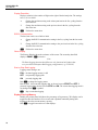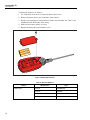
1
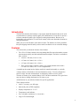
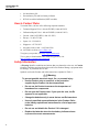
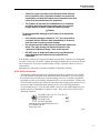
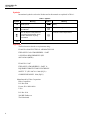
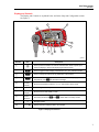
1551A Ex/1552A Ex
Stik Thermometer
Users Manual
November 2010
© 2010 Fluke Corporation. All rights reserved. Specifications are subject to change without notice.
All product names are trademarks of their respective companies.
LIMITED WARRANTY AND LIMITATION OF LIABILITY
Each Fluke product is warranted to be free from defects in material and workmanship under normal use and
service. The warranty period is one year and begins on the date of shipment. Parts, product repairs, and
services are warranted for 90 days. This warranty extends only to the original buyer or end-user customer of
a Fluke authorized reseller, and does not apply to fuses, disposable batteries, or to any product which, in
Fluke's opinion, has been misused, altered, neglected, contaminated, or damaged by accident or abnormal
conditions of operation or handling. Fluke warrants that software will operate substantially in accordance
with its functional specifications for 90 days and that it has been properly recorded on non-defective media.
Fluke does not warrant that software will be error free or operate without interruption.
Fluke authorized resellers shall extend this warranty on new and unused products to end-user customers
only but have no authority to extend a greater or different warranty on behalf of Fluke. Warranty support is
available only if product is purchased through a Fluke authorized sales outlet or Buyer has paid the
applicable international price. Fluke reserves the right to invoice Buyer for importation costs of
repair/replacement parts when product purchased in one country is submitted for repair in another country.
Fluke's warranty obligation is limited, at Fluke's option, to refund of the purchase price, free of charge repair,
or replacement of a defective product which is returned to a Fluke authorized service center within the
warranty period.
To obtain warranty service, contact your nearest Fluke authorized service center to obtain return
authorization information, then send the product to that service center, with a description of the difficulty,
postage and insurance prepaid (FOB Destination). Fluke assumes no risk for damage in transit. Following
warranty repair, the product will be returned to Buyer, transportation prepaid (FOB Destination). If Fluke
determines that failure was caused by neglect, misuse, contamination, alteration, accident, or abnormal
condition of operation or handling, including overvoltage failures caused by use outside the product’s
specified rating, or normal wear and tear of mechanical components, Fluke will provide an estimate of repair
costs and obtain authorization before commencing the work. Following repair, the product will be returned to
the Buyer transportation prepaid and the Buyer will be billed for the repair and return transportation charges
(FOB Shipping Point).
THIS WARRANTY IS BUYER'S SOLE AND EXCLUSIVE REMEDY AND IS IN LIEU OF ALL OTHER
WARRANTIES, EXPRESS OR IMPLIED, INCLUDING BUT NOT LIMITED TO ANY IMPLIED WARRANTY
OF MERCHANTABILITY OR FITNESS FOR A PARTICULAR PURPOSE. FLUKE SHALL NOT BE LIABLE
FOR ANY SPECIAL, INDIRECT, INCIDENTAL, OR CONSEQUENTIAL DAMAGES OR LOSSES,
INCLUDING LOSS OF DATA, ARISING FROM ANY CAUSE OR THEORY.
Since some countries or states do not allow limitation of the term of an implied warranty, or exclusion or
limitation of incidental or consequential damages, the limitations and exclusions of this warranty may not
apply to every buyer. If any provision of this Warranty is held invalid or unenforceable by a court or other
decision-maker of competent jurisdiction, such holding will not affect the validity or enforceability of any other
provision.
Fluke Corporation
P.O. Box 9090
Everett, WA 98206-9090
U.S.A.
Fluke Europe B.V.
P.O. Box 1186
5602 BD Eindhoven
The Netherlands
11/99
To register your product online, visit register.fluke.com
Table of Contents
Title
Introduction........................................................................................................
Features..............................................................................................................
How to Contact Fluke ........................................................................................
Safety Information .............................................................................................
ATEX Safety Information .............................................................................
Symbols .........................................................................................................
Approvals ......................................................................................................
Operation ...........................................................................................................
Immersion Depth and Usage .........................................................................
Display and Controls .....................................................................................
Primary Display ........................................................................................
Stability Display........................................................................................
Setup and Configuration................................................................................
Temperature Unit Selection ......................................................................
Stability Limit ...........................................................................................
Auto-Off Selection ....................................................................................
Battery Life ...............................................................................................
Operating Temperature .............................................................................
Damping....................................................................................................
Sampling Rate ...........................................................................................
Display Resolution ....................................................................................
RS232 Communication .............................................................................
Ohms Display............................................................................................
Start or Stop Data Logging .......................................................................
Display Free Log Memory ............................................................................
Logging Interval........................................................................................
Send Logged Data .....................................................................................
Erase Logged Data ....................................................................................
Maintenance.......................................................................................................
Clean the Product ..........................................................................................
Battery Replacement .....................................................................................
Battery Life....................................................................................................
Calibration .....................................................................................................
SCPI Commands................................................................................................
RS-232 Interface ................................................................................................
Specifications.....................................................................................................
i
Page
1
1
2
2
3
4
4
5
5
7
8
8
8
8
8
9
9
9
9
9
10
10
10
10
10
11
11
11
11
11
11
13
13
13
13
13
1551A Ex/1552A Ex
Users Manual
ii
List of Tables
Table
1.
2.
Title
Page
Symbols.................................................................................................................. 4
Approved Batteries................................................................................................. 12
iii
1551A Ex/1552A Ex
Users Manual
iv
List of Figures
Figure
Title
1.
2.
3.
4.
Probe Measurements ..............................................................................................
Immersion Depth....................................................................................................
Display and Controls..............................................................................................
Battery Replacement ..............................................................................................
v
Page
5
6
7
12
1551A Ex/1552A Ex
Users Manual
vi
Introduction
The Stik Thermometer (the Product) is a precision digital thermometer that can be used
as an alternative to mercury liquid-in-glass (LIG) thermometers. It can also be used as a
reference standard for other types of digital or analog thermometers. Because of its
intrinsically safe certification, it can be used in many of the same hazardous locations as
analog thermometers.
When you receive the Product, check that it is intact. The batteries are factory installed.
Keep the shipping materials until you have made sure that there is no concealed damage.
Features
This section tells you about the features of the Product.
•
The 1551A Ex Probe contains a fast-responding thin-film sensor that makes accurate
measurements quickly and with minimal immersion depth. The Probe is available in
three versions:
•
4.8 mm x 229 mm (3/16 in. x 9 in.)
•
6.35 mm x 305 mm (1/4 in. x 12 in.)
•
6.35 mm x 508 mm (1/4 in. x 20 in.)
•
The 1552A Ex Probe contains a stable, wire-wound platinum sensor with a
6.35 mm x 305 mm (1/4 in. x 12 in.) length sheath.
A rotatable probe mount lets the display module be turned horizontally or vertically.
A unique feature of the Product is the trend indication arrows. You can configure the
arrows to show when the measurements are adequately stable to record a result.
The auto-off feature gives extended battery life of 300 hours maximum. The typical user
may only have to change the batteries a few times a year.
Added features let you tailor the Product for specific applications.
These features include:
•
±0.05 °C accuracy over full range
•
Intrinsically safe (ATEX compliant)
•
Display temperature in °C or °F
•
Temperature trend indicator
•
User-selectable resolution (0.1, 0.01, 0.001)
•
Large LCD with backlight
1
1551A/1552A Ex
Users Manual
•
300 hour battery life
•
Percent battery life and low-battery indicator
•
NVLAP accredited calibration (NIST traceable)
How to Contact Fluke
To contact Fluke, call one of the following telephone numbers:
•
Technical Support USA: 1-800-44-FLUKE (1-800-443-5853)
•
Calibration/Repair USA: 1-888-99-FLUKE (1-888-993-5853)
•
Canada: 1-800-36-FLUKE (1-800-363-5853)
•
Europe: +31 402-675-200
•
Japan: +81-3-3434-0181
•
Singapore: +65-738-5655
•
Anywhere in the world: +1-425-446-5500
Or, visit Fluke's website at www.fluke.com.
To register your product, visit http://register.fluke.com.
To see, print, or download the latest manual supplement, visit
http://us.fluke.com/usen/support/manuals.
Safety Information
A Warning identifies conditions and actions that pose hazard(s) to the user. A Caution
identifies conditions and procedures that could cause Product damage, equipment under
test damage, or permanent loss of data.
Symbols used on the Product and in this manual are explained in Table 1.
XWWarning
To prevent possible electrical shock, fire, or personal injury:
2
•
Use the Product only as specified, or the protection
supplied by the Product can be compromised.
•
Do not use the Product to measure the temperature of
hazardous live components.
•
Do not open the Product case. If you open the case, the Ex
approval is not applicable.
•
Change the batteries only in areas that are not Ex-hazardous.
•
Use only specified approved batteries in the Product. Refer
to the battery replacement instructions for a list of approved
batteries.
•
Do not use and disable the Product if it is damaged.
•
Replace the batteries when the low battery indicator shows
to prevent incorrect measurements.
Stik Thermometer
Safety Information
•
Check for proper operation of the Product before taking it
into a hazardous area. Should the Product not operate as
expected do not take the Product into a hazardous area and
return it to the manufacturer for inspection.
•
The Product is intended for installation only in locations
providing adequate protection against the entry of solid
foreign objects or water capable of impairing safety.
WCaution
To prevent possible damage to the Product or to equipment
under test:
•
If the display message changes to “OL,” the range limit is
exceeded and the Product must immediately be removed
from the heat source to prevent damage.
•
Do not immerse the Probe beyond its maximum immersion
depth. This may damage its internal electronics. See
“Immersion Depth and Usage” later in this manual.
•
DO NOT drop or strike the Probe in any way. Mechanical
shock damages the Probe internally and affects it
calibration.
If the Product overheats or is exposed to sudden physical shock, examine it for damage that
can cause a safety risk. If possible, compare the displayed temperature to a known reference
before Product use. If not sure, send the Product to Fluke Corporation. Refer to “How to
Contact Fluke”.
Substitution of components will impair suitability for hazardous locations.
ATEX Safety Information
This manual contains data and safety regulations that must be followed for safe, reliable
use of the Product in hazardous areas under the detailed conditions. If you do not follow
these instructions, personal injury or Product damage can occur. Violation of applicable
legislation can also occur. Read the full manual before you use the Product. To make sure
of safe Product operation, fully follow all instructions and warnings in the manual. If you
are not sure (due to translation and/or printing errors), refer to the English manual.
An “Ex-hazardous area,” as used in this manual, refers to an area made hazardous by the
possible presence of flammable or explosive vapors. These areas are also referred to as
“hazardous locations.”
Ex ib IIB T4 Gb (–10 °C ≤ Ta ≤ +50 °C)
ITS10ATEX27114X
Ex ib IIB T4 Gb
II 2 G IECEx ITS10.0049
0344
Manufactured by Martel Electronics, Inc.,
3 Corporate Park Dr.
Derry, NH, USA
gjo006.eps
3
1551A/1552A Ex
Users Manual
Symbols
International symbols used on the Product and in this manual are explained in Table 1.
Table 1. Symbols
Symbol
J
Meaning
Earth ground
Symbol
M
Risk of Danger. Important information.
See Manual.
W
X
~
Do not dispose of this product as
unsorted municipal waste. Go to
Fluke’s website for recycling
information.
P
Conforms to relevant European Union directives.
Meaning
Battery
Hazardous Voltage
Conforms to ATEX requirements
(
Approvals
The Product meets the above requirements using:
EN 60079-0:2006 ELECTRICAL APPARATUS FOR
EXPLOSIVE GAS ATMOSPHERES -- PART
0: GENERAL REQUIREMENTS (IEC
60079-0:2004 (MOD))
EN 60079-11:2007
EXPLOSIVE ATMOSPHERES -- PART 11:
EQUIPMENT PROTECTION BY INTRINSIC
SAFETY "I" (IEC 60079-11:2006 (EQV) +
CORRIGENDUM DEC. 2006 (EQV))
Manufactured by Fluke Corporation:
Fluke Corporation
P.O. Box 9090
Everett, WA 98206-9090
U.S.A.
P.O. Box 1186
5602 BD Eindhoven
The Netherlands
4
Stik Thermometer
Operation
Operation
Immersion Depth and Usage
WCaution
To prevent possible damage to the Product or to equipment
under test, do not immerse the Probe beyond the maximum
immersion depth. This may damage its internal electronics.
Allow enough time for the Probe to stabilize before recording measurements. Use the
Stability Display to determine when the Probe has stabilized.
Probe sensor length is shown in Figure 1.
3
1
2
gjo004.eps
A
Sheath Length:
1551A-9: 229 mm (9 in)
1551A-20: 508 mm (20 in)
1551A-12/1552A-12: 305 mm (12 in)
B
Sensor Length:
1551A: ≤10 mm (0.39 in)
1552A: ≤30 mm (1.18 in)
C
Sheath Diameter:
1551A-9: 4.8 mm (3/16 in)
1551A-12/1551A-20/1552A: 6.35 mm (1/4 in)
Figure 1. Probe Measurements
5
1551A/1552A Ex
Users Manual
The minimum immersion depth for the Probe is 3.5 inches in a stirred fluid heat source. It
is recommended that you make sure of the minimum immersion depth for the specific
application. See Figure 2.
•
The maximum immersion depth for the 1551A Ex is 2 inches less than the total
length. Make sure the last 2 inches of Probe, nearest to the internal electronics of the
device, are not put into the heat source.
•
The maximum immersion depth for the 1552A Ex is 3 inches less than the total
length. Make sure the last 3 inches of the Probe, nearest to the internal electronics of
the device, are not put into the heat source.
gjo002.eps
A
1552A Ex: Maximum immersion: 3 inches less than total probe length.
B
1551A Ex: Maximum immersion: 2 inches less than total probe length.
Figure 2. Immersion Depth
6
Stik Thermometer
Operation
Display and Controls
The Display and Controls are explained below and in the Setup and Configuration section.
See Figure 3.
7
6
5
10
9
1
3
2
4
8
gjo001.eps
Number
Item
A
D
B
A
B
C
C
D
Description
Push to power the Product on and off. Hold the button down at power-up to
check the display to see that all display segments are shown.
Push to toggle the main display value between min, max, and trend modes.
Push to change the various set-up parameters of the Product.
Push to enter data in set-up modes. When the Product is displaying
temperature, push C to activate the backlight.
E
Primary
Display
Shows the temperature values in °C or °F. Also used in set-up mode.
F
Icon area
Used in regular and setup modes.
G
Stability
Display
Shows the trend and stability of data.
H
Arrow
Buttons
Secondary functions of Aand B. Enter data in the setup modes.
I
J
M
E
Backlight symbol.
Flashes when the batteries need to be changed.
Figure 3. Display and Controls
7
1551A/1552A Ex
Users Manual
Primary Display
Push Ato toggle the numeric display between the current reading, minimum,
maximum, and 1-minute trend values in °C or °F as calculated since power up or since
the last reset of values. Push and hold the A button for 2 seconds until "CLR" shows
to reset the MIN/MAX/TREND values.
Stability Display
The Stability Display shows the general stability level relative to a user-configurable
stability limit. There are four presets for stability shown in °C or °F (0.01, 0.1, 1.0, or
10.0). When the limit is exceeded, it also shows the general direction in which the
readings are presently moving. The stability level is calculated from a moving sample
window of 6 seconds, with the value extrapolated to a 1-minute time base.
Segments are turned on to indicate the stability level as follows:
•
Center only (stable) - when half of the 1-minute trend value is less than or equal to
the stability limit, i.e. maximum deviation -limit to +limit.
•
Center plus one arrow up or down (depending on the trend) - when half of the 1minute trend value is greater than the stability limit and is less than or equal to twice
the stability limit.
•
Center plus two arrows up or down (depending on the trend) - when half of the 1minute trend value is greater than twice the stability limit and is less than or equal to
three times the stability limit.
•
Center plus three arrows up or down (depending on the trend) - when half of the 1minute trend value is greater than three times the stability limit.
Setup and Configuration
Push B to enter the setup modes. Inside the setup modes the buttons work as follows:
A
Exit to the main display.
B
Step to the next menu item, exit to the main display after the last item.
C
Enter the data-edit mode for the present menu item.
During the data-edit mode, use K and L to scroll through the values. Push C to save
and exit back to the menu item.
The following sections describe the setup items in the order in which they appear.
Temperature Unit Selection
The Temperature Unit Selection Menu lets you choose the unit used when showing the
primary variable.
K
Change the unit °C or °F.
L
Change the unit °C or °F.
C
Exit back to menu item
Stability Limit
The stability limit setting is used to find when the secondary display will show that the
reading is stable. There are four preset settings for stability (0.01, 0.1, 1.0, or 10.0)
expressed in the presently selected units.
8
K
Change the unit-stability limit setting to the next greater setting.
L
Change the unit-stability limit setting to the next lesser setting.
C
Exit back to menu item
Stik Thermometer
Operation
Auto-Off Selection
The Auto-off parameters control when the Product automatically turns off after inactivity
on the keypad.
K
Increase the auto-off setting and the primary data field from "OFF" to 1 minute
and stopping at 20 minutes.
L
Decrease the auto-off setting and the primary data field from 1 minute to "OFF"
and stopping at "OFF".
C
Exit back to menu item.
Battery Life
Initially, the primary data field shows the percentage of remaining battery life. This
display can be toggled to show the battery voltage and is constantly updated to show
current battery capacity.
Push C to toggle between the two data displays.
Operating Temperature
This selection shows the operating temperature of the internal electronics in °C or °F.
K
Change the unit °C or °F.
L
Change the unit °C or °F.
C
Exit back to menu item.
Note
An “Overtemp” warning is shown if the internal electronics temperature
is more than 50 °C (122 °F).
Damping
The Damping function is a running average of readings used to filter "noisy" temperature
sources. The selections are OFF, 2, 5, or 10 sample average.
K
Change the damp setting to the subsequent item in the list, cycling from the last
to the first.
L
Change the damp setting to the previous item in the list, cycling from the first to
the last.
C
Exit back to menu item.
Sampling Rate
The sampling rate calculates how often the Product samples data. The settings are 0.5, 1.0,
or 2.0, shown in samples per second.
K
Change the rate setting to the subsequent item in the list, cycling from the last to
the first.
L
Change the rate setting to the previous item in the list, cycling from the first to
the last.
C
Exit back to menu item.
9
1551A/1552A Ex
Users Manual
Display Resolution
Display resolution is the number of digits to the right of the decimal point. The settings
are 0.1, 0.01, or 0.001.
K
Change the resolution setting to the subsequent item in the list, cycling from the
last to the first.
L
Change the resolution setting to the previous item in the list, cycling from the
first to the last.
C
Exit back to menu item.
RS232 Communication
The baud rate can be set to 2400 or 9600.
K
Change the RS232 communication setting in the list, cycling from the last to the
first.
L
Change the RS232 communication setting to the previous item in the list, cycling
from the first to the last.
C
Exit back to menu item.
Ohms Display
The Primary Display shows the resistance of the sensor. The secondary data field
displays “OHMS”. C is inactive.
Note
The Data Logging functions that follow are only functional in Products that
were purchased with option Data Logging configuration (e.g. 155X-D-X).
Start or Stop Data Logging
Logging status messages are:
FULL the data logging memory is full
OFF
not presently logging data
ON
presently logging data
Push C to change the logging status.
Push K and L if not currently logging data, to choose between START and OFF. If
presently logging data, choose between STOP and ON. The current data logging mode is
not changed until C is pushed.
C
Stop or start data logging.
Display Free Log Memory
Initially, the primary data field shows the percentage of log memory. This display can be
toggled to show the number of free records and is updated continually during data
logging to show the current memory capacity.
Push C to toggle between the two data displays.
10
Stik Thermometer
Maintenance
Logging Interval
Push C to enter the data edit mode. ENTER is ignored if presently logging data.
K
Change the logging interval setting to the subsequent item in the list, cycling
from the last to the first.
L
Change the logging interval setting to the previous item in the list, cycling from
the first to the last.
C
Return to the corresponding menu item.
Send Logged Data
Push C to:
K or L
Confirm or cancel the choice to send data.
C
Send or cancel data.
C
is ignored if presently logging data.
Erase Logged Data
Push C to:
K or L
Confirm or cancel the choice to erase logged data.
C
Erase or cancel data erase.
C
is ignored if presently logging data.
Maintenance
Clean the Product
WCaution
To prevent possible damage to the product or to equipment
under test, do not use abrasive cleaners. They will damage the
case.
To clean the Product, use a cloth with a mild cleaning solution.
Battery Replacement
XWWarning
To prevent possible explosion, fire, or personal injury:
•
Change the batteries only in areas that are not Ex-hazardous.
•
Replace the batteries when the low battery indicator shows
to prevent incorrect measurements.
WCaution
To prevent possible damage to the Product or to equipment
under test:
•
Remove batteries to prevent battery leakage and damage to
the Product if it is not used for an extended period.
•
Be sure that the battery polarity is correct to prevent battery
leakage.
11
1551A/1552A Ex
Users Manual
To change the batteries, see Figure 4:
1. Use a flat-blade screwdriver to remove the battery door screw.
2. Remove the battery door to access the three AAA batteries.
3. Replace only with approved AAA batteries listed in this document. See Table 2. Any
substitution voids the Product safety rating.
4. Make sure the battery polarity is correct.
5. Replace the battery door and install the screw.
gjo003.eps
Figure 4. Battery Replacement
Table 2. Approved Batteries
Battery
Alkaline AAA
12
Manufacturer
Type
Duracell
LR03/MN2400
Rayovac
LR03/824
Energizer
LR03/E92
Panasonic
LR03X
Stik Thermometer
SCPI Commands
Battery Life
Battery life is approximately 300 hours (12.5 days) of continuous operation with the
backlight off. A low-battery icon (E) shows in the lower right of the display when
battery level is low. Replace batteries per recommendations found in the specifications
section of this manual.
Calibration
For calibration information, refer to the document on the documentation CD.
SCPI Commands
For a list of the SCPI commands, refer to the document on the documentation CD.
RS-232 Interface
An RS-232 interface is standard on the Product. Serial communication can be used for
configuration, calibration, and to move measurement data from the Product. An RS-232
cable is included with data logging software purchase.
XWWarning
To prevent possible electrical shock, fire, or personal injury, the
RS-232 interface must not be used in hazardous areas.
Specifications
(Ambient: 23 °C ±5 °C)
Measurement Range
1551A Ex ......................................................................... −50 °C to 160 °C (−58 °F to 320 °F)
1552A Ex ......................................................................... −80 °C to 300 °C (−112 °F to 572 °F)
Accuracy (1 year) ..................................................................... ±0.05 °C (0.09 °F)
Resolution ................................................................................. Selectable (0.1, 0.01, 0.001) factory default is 0.01
Sample Rate ............................................................................. User selectable 0.5/sec, 1/sec or 2/sec factory default is
1/sec
Operating Temperature Range of Readout: .......................... −10 °C to 50 °C (14 °F to 122 °F)
Probe Response Time .............................................................. Approximately 20 seconds
EMC Compliance....................................................................... EN61326:2006 Annex C
CISPR 11, Edition 5.0-2009
Class “B”
Humidity Range......................................................................... 0 to 95 % RH Non-condensing
Storage Temperature Range.................................................... −20 °C to 60 °C (−4 °F to 140 °F)
Enclosure Rating ...................................................................... IP50
Readout Temperature Coefficient ........................................... Add ±10 ppm/°C of full scale temperature from −10 °C to
18 °C and 28 °C to 50 °C
Probe Temperature Coefficient .............................................. 0.00385 Ω/Ω/°C nominal
Nominal Probe Resistance at 0 °C .......................................... 100 Ω
Probe Hysteresis....................................................................... ±0.01 °C
Power ......................................................................................... 3 AAA alkaline batteries
(Must use only approved batteries. See Table 2)
13
1551A/1552A Ex
Users Manual
Battery Life ................................................................................ Approximately 300 hours without back light
Battery Save (auto-off) Range ................................................. Selectable from 1 to 30 minutes or can be disabled
Size (readout only).................................................................... Approximately 4 in. x 2 in. x 1 in.
Probe Size.................................................................................. 1551A-9: 4.8 mm x 229 mm (3/16 in. x 9 in.)
1551A-12: 6.35 mm x 305 mm (1/4 in. x 12 in.)
1551A-20: 6.35 mm x 508 mm (1/4 in. x 20 in.)
1552A: 6.35 mm x 305 mm (1/4 in. x 12 in.)
Weight ........................................................................................ 6.9 oz
14