1
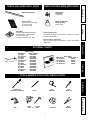
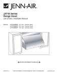
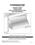
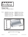
®
Range Hood
Use & Care / Installation Manual
Models
FSH301-WH (30” wide - White)
FSH301-SS (30” wide - Stainless)
FSH301-BL (30” wide - Black)
FSH361-WH (36” wide - White)
FSH361-SS (36” wide - Stainless)
FSH361-BL (36” wide - Black)
FSH481-WH (48” wide - White)
FSH481-SS (48” wide - Stainless)
FSH481-BL (48” wide - Black)
FSH601-WH (60” wide - White)
FSH601-SS (60” wide - Stainless)
FSH601-BL (60” wide - Black)
HB0026
!
V05650 rev.D
INTENDED FOR DOMESTIC COOKING ONLY
FIVESTAR, Cleveland, TN 37320-2490
!
www.fivestarrange.com
READ AND SAVE THESE INSTRUCTIONS
TABLE OF CONTENTS
SECTION ..................................................................... PAGE
Warranty .............................................................................. 2
Safety Instructions ............................................................... 3
Operation ............................................................................. 4
Cleaning .............................................................................. 4
Parts Included With Hood ................................................... 5
Parts Not Included With Hood ............................................ 5
Optional Parts ...................................................................... 5
Tools Needed ...................................................................... 5
SECTION ..................................................................... PAGE
FIVESTAR Range Hood System ............................................. 6
Prepare The Hood Location ............................................... 7
Prepare The Hood .............................................................. 8
Install The Hood .................................................................. 9
Connect The Wiring .......................................................... 10
Wiring Diagram ................................................................. 10
Finalize the Installation ..................................................... 10
Install The Filters ............................................................... 11
Service Parts ..................................................................... 12
WARRANTY
LIMITED WARRANTY
FIVESTAR
RANGE HOODS
This product has been designed for domestic household use. If properly installed and operated under normal conditions in accordance with the printed instructions,
it will satisfactorily perform the functions that are generally expected of this type of product.
ONE YEAR PARTS AND LABOR
If this product fails to do so because of a defect in material or workmanship within one year from the date of original purchase:
We will at our option, repair, exchange, or correct by other means we consider appropriate, any part(s) we find to be defective except for the finish, warming lamps,
and lamp bulbs. Any parts to be replaced or repaired will be warranted only for the balance of the original year.
OWNERSHIP
This warranty remains in force for the time period mentioned above from the date of original retail purchase. YOU MUST KEEP YOUR RECEIPT AS PROOF OF
THE DATE OF ORIGINAL PURCHASE.
WARRANTY CONDITIONS
This warranty DOES NOT apply to any product that has been subjected to alteration, misuse, abuse (including damage by foreign agents or chemicals), accident,
improper installation, delivery damage, or other than normal household use and service.
This warranty does not apply to the stainless steel finish as it is specifically dependent upon proper care by the use. We warrant only that it is manufactured to
a commercially acceptable standard and conforms to it at time of delivery.
This warranty is LIMITED STRICTLY to the terms indicated herein, and no other expressed warranties or remedies thereunder shall be binding on us. TO THE
EXTENT CONSISTENT WITH STATE AND FEDERAL LAWS: (1) ANY IMPLIED WARRANTIES SHALL BE LIMITED TO THE SAME TIME PERIOD STATED HEREIN
FOR THE EXPRESSED WARRANTIES, AND (2) WE SHALL NOT BE LIABLE FOR ANY INCIDENTAL OR CONSEQUENTIAL DAMAGES UNDER ANY EXPRESSED
OR IMPLIED WARRANTIES RELATING TO THE PRODUCT.
The warranty obligation on this product outside the contiguous 48 U.S. States and the District of Columbia shall be LIMITED STRICTLY to furnishing replacement
parts and shall EXCLUDE service labor.
FEDERAL REGULATORY PROVISIONS
Some states or provinces do not allow limitations on how long an implied warranty lasts nor limitations or exclusions of incidental or consequential damages, so
the above limitations or exclusions may not apply to you. This warranty gives you specific legal rights, and you may also have other rights which vary from state
to state, or province to another, as well as rights under Federal Laws.
PURCHASER'S RESPONSIBILITIES
The purchaser will be responsible for the costs of any service calls requested to demonstrate or confirm the proper operation of the product, to correct an improper
installation, or to correct malfunctions in the product created by the operation in a manner not prescribed by or cautioned against in the instructions.
MODEL NUMBER
The model number can be found on a label attached to the hood. The purchaser should always use the model number and hood size when talking to or writing to
the dealer or builder from whom this product was purchased or the local authorized service agency.
FACTORY ASSISTANCE
If the purchaser is unable to located an authorized service agency, or if the purchaser does not receive satisfaction from the source from whom the product was
purchased, or from the local service agency, write to: CUSTOMER SERVICE DEPARTMENT, P.O. BOX 2490, CLEVELAND, TN 37320
2
SAFETY INSTRUCTIONS
TO REDUCE THE RISK OF FIRE, ELECTRIC SHOCK, OR
INJURY TO PERSONS, OBSERVE THE FOLLOWING:
1. Use this unit only in the manner intended by the manufacturer.
If you have questions, contact the manufacturer at the
address listed in the warranty.
2. Before servicing or cleaning unit, switch power off at service
panel and lock the service disconnecting means to prevent
power from being switched on accidentally. When the
service disconnecting means cannot be locked, securely
fasten a prominent warning device, such as a tag, to the
service panel.
3. Installation work and electrical wiring must be done by a
qualified person(s) in accordance with all applicable codes
and standards, including fire-rated codes and standards.
4. Sufficient air is needed for proper combustion and
exhausting of gases through the flue (chimney) of fuel
burning equipment to prevent backdrafting. Follow the
heating equipment manufacturer’s guideline and safety
standards such as those published by the National Fire
Protection Association (NFPA), and the American Society
for Heating, Refrigeration and Air Conditioning Engineers
(ASHRAE), and the local code authorities.
5. When cutting or drilling into wall or ceiling, do not damage
electrical wiring and other hidden utilities.
6. Do not use this range hood with any additional solid state
speed control device.
7. Ducted fans must always be vented to the outdoors.
8. To reduce the risk of fire, use only steel ductwork.
9. This unit must be grounded.
TO REDUCE THE RISK OF A RANGE TOP GREASE FIRE:
1. Never leave surface units unattended at high settings.
Boilovers cause smoking and greasy spillovers that may
ignite. Heat oils slowly on low or medium settings.
2. Always turn hood ON when cooking at high heat or when
cooking flaming foods.
3. Clean ventilating fans frequently. Grease should not be
allowed to accumulate on fan or filter.
4. Use proper pan size. Always use cookware appropriate
for the size of the surface element.
TO REDUCE THE RISK OF INJURY TO PERSONS IN THE
EVENT OF A RANGE TOP GREASE FIRE, OBSERVE THE
FOLLOWING:*
1. SMOTHER FLAMES with a close-fitting lid, cookie sheet,
or metal tray, then turn off the burner. BE CAREFUL TO
PREVENT BURNS. If the flames do not go out immediately,
EVACUATE AND CALL THE FIRE DEPARTMENT.
2. NEVER PICK UP A FLAMING PAN - You may be burned.
3. DO NOT USE WATER, including wet dishcloths or towels
- This could cause a violent steam explosion.
4. Use an extinguisher ONLY if:
A. You know you have a Class ABC extinguisher and you
already know how to operate it.
B. The fire is small and contained in the area where it started.
C. The fire department is being called.
D. You can fight the fire with your back to an exit.
* Based on “Kitchen Firesafety Tips” published by NFPA.
Safety
WARNING
Warranty
WARNING
CAUTION !
Operation
Cleaning
Installation
1. For general ventilating use only. Do not use to exhaust
hazardous or explosive materials and vapors.
2. To avoid motor bearing damage and noisy and/or
unbalanced impellers, keep drywall spray, construction
dust, etc. off power unit.
3. Your hood motor has a thermal overload which will
automatically shut off the motor if it becomes overheated.
The motor will restart when it cools down. If the motor
continues to shut off and restart, have the hood serviced.
4. For best capture of cooking impurities, the bottom of the
hood should be a minimum of 24” and a maximum of 30”
above the cooking surface.
5. To reduce the risk of fire and to properly exhaust air on a
ducted installation, be sure to duct air outside - Do not
exhaust air into spaces within walls or ceiling or into attics,
crawl spaces, or garage.
6. This product is equipped with a thermostat which may
start blower automatically. To reduce the risk of injury and
to prevent power from being switch on accidentally, switch
power off at service panel and lock or tag service panel.
7. To reduce the risk of fire and electric shock, the FIVESTAR
hood must be installed with FIVES TAR blower models
FBK600, FBK1200 or exterior blower model 332H only.
Other blowers cannot be substituted. (Blowers sold
separately).
8. Use with approved cord-connection kit only.
9. Please read specification label on product for further
information and requirements.
Service Parts
3
OPERATION
CLEANING
Always turn ON your hood before you begin cooking in order
to establish an air flow in the kitchen. Let the blower run for a
few minutes to clear the air after you turn off the range. This
will help keep the whole kitchen cleaner and brighter.
Grease filters
The grease filters should be cleaned frequently. Use a warm
detergent solution. Grease filters are dishwasher safe.
Wash more often if your cooking style generates greater
grease - like frying foods or wok cooking.
Remove filters by pushing filters towards the back of hood
and rotating filters downward.
Blower Cleaning
Remove the grease filters in order to access the blower.
Vacuum blower to clean. Do not immerse in water. Refer to
blower instruction manual for more details.
Grease Rail
The grease rail should be cleaned frequently, especially if
baffle filters are used. Remove filters, then, disassemble the
grease rail from the hood by removing its 3 retaining screws.
See illustration below.
4
3
6
1
3 5
1
2
3
HC0004
1. Warming lamps
2. Warming lamp switches
3. Halogen lights
4. Halogen light switches
5. ON/OFF Blower switch
6. Blower speed control
Warming Lamps (Infrared)
Each warming lamp (item 1 on picture above) is controlled
with is own ON/OFF switch (item 2 on picture above).
Use only BR40 Size, 250W Max., Infrared bulbs. (Purchase
separately.)
WARNING: Do not place highly flammable
material on warming shelves.
Cooktop Lighting (Halogen)
A double set of ON/OFF switches (item 4 on picture above)
control the halogen lights (item 3 on picture above).
The front rocker controls the center light. The rear rocker
controls both side lights. Select one, two, or three lights for
best cooktop lighting.
Use PAR 20, 50W halogen bulbs. (Purchase separately.)
Blower
The blower is operated using two (2) controls.
Use the ON/OFF blower switch (item 5 on picture above) to
start and stop the blower. When turned on, the blower will
operate at the previous setting of the speed control (item 6 on
the picture above).
Turn the speed control knob clockwise to decrease blower
speed - counterclockwise to increase speed.
HEAT SENTRYTM
Your hood is equipped with a HEAT SENTRYTM thermostat.
This thermostat is a device that will turn on or speed up the
blower if it senses excessive heat above the cooking surface.
1) If blower is OFF - it turns blower ON to high speed.
2) If blower is ON at a lower speed setting - it turns blower up
to HIGH speed.
When the temperature level drops to normal, the blower will
return to its original setting.
WARNING: The HEAT SENTRYTM thermostat can
start the blower even if the hood is turned OFF.
When this occurs, it is impossible to turn the
blower OFF with the switch. If you must stop
the blower, do it from the main electrical panel.
4
HD0069
Refer to Stainless steel cleaning in Hood Cleaning section
below. Once the grease rail is clean and dry, reassemble it to
the hood and reinstall filters.
Hood Cleaning
Stainless steel cleaning: How to maintain its ‘’BRIGHT LOOK’’
Do:
- Regularly wash surfaces with clean cloth or rag soaked
with warm water and mild soap or liquid dish detergent.
- Always clean in the diredtion of original polish lines.
- Always rinse well with clear water (2 or 3 times) after cleaning.
Wipe dry completely.
- You may also use a specialized household stainless steel
cleaner.
Don’t:
- Do not use any steel or stainless steel wool or any other
scrapers to remove stubborn dirt.
- Do not use any harsh or abrasive cleaners.
- Do not allow dirt to accumulate.
- Do not let plaster dust or any other construction residues
reach the hood. During construction/renovation, cover the
hood to make sure no dust sticks to stainless steel surface.
Avoid: when choosing a detergent
- Any cleaners that contains bleach will attack stainless steel.
- Any products containing: chloride, fluoride, iodide,
bromide will deteriorate surfaces rapidly.
- Any combustible products used for cleaning such as
acetone, alcohol, ether, benzol, etc., are highly explosive
and should not be used close to a range.
Enamel finish: Clean with warm water and detergent only.
When discoloration occurs, use a good enamel polish such
as automotive polish. (DO NOT use rough abrasive cleaner
or porcelain cleaner.)
PARTS INCLUDED WITH HOOD
PARTS NOT INCLUDED WITH HOOD
Warranty
Wood mounting strip
PAR 20 50W
Light Bulb
(3 per hood)
Grease Filters
(3 per 30’’ and 36’’ hood)
(4 per 48’’ hood)
(5 per 60’’ hood)
BR40, 250W Max.
Warming Lamp
(2 per hood)
Ducting Accessories
(See “FIVESTAR Range Hood System” on page 6 for Ducting
Accessory Model Nos.)
Safety
Parts Bag
(includes 4 flat head screws #10-2’’,
8 screws #8-3/4’’, 4 Nuts #10-32,
2 Wall anchors and
2 Washers 3/16’’ ID x 3/4’’ OD)
Blower (interior OR exterior)
(See “FIVESTAR Range Hood System” on page 6 for Blower
Model Nos.)
Operation
OPTIONAL PARTS
Soffit Chimney
Description
Model Number
30’’ White
FDC30-WH
30’’ Stainless
FDC30-SS
30’’ Black
FDC30-BL
36’’ White
FDC36-WH
36’’ Stainless
FDC36-SS
36’’ Black
FDC36-BL
48’’ White
FDC48-WH
48’’ Stainless
FDC48-SS
48’’ Black
FDC48-BL
60’’ White
FDC60-WH
60’’ Stainless
FDC60-SS
60’’ Black
FDC60-BL
Backsplash
Description
Model Number
30’’ Stainless
FBS30
36’’ Stainless
FBS36
48’’ Stainless
FBS48
60’’ Stainless
FBS60
Cleaning
TOOLS NEEDED FOR HOOD INSTALLATION
Sabre
Keyhole
Saw -or- Saw
Duct Tape
5
3/8”
Nutdriver
Wire
Stripper
Service Parts
Drill
Tape
Measure
Pencil
Installation
Screwdriver
(Robertson or Phillips)
FIVESTAR RANGE HOOD SYSTEM
Wall & Roof Caps,
Exterior Blower
Model 332H
(900 cfm)
Exterior Blower
Model 437
High Capacity
Roof Cap
Model 441
10’’ Round
Wall Cap
Model 647
7’’ Round
Wall Cap
Model 634
or 644
Roof Cap
Elbows and
In-Line Dampers
Model 418
10’’ Round
Adjustable Elbow
Model 421
10’’ Round Vertical
In-Line Damper
Model 415
7’’ Round
Adjustable Elbow
Ductwork
Choose 1 of 5
Discharge
Transitions
Model 410
10’’ Round Duct
(2 ft. sections)
Model 427
Model 423
Model 424
(4 ½’’ x 18 ½’’ (4 ½’’ x 18 ½’’ to (4 ½’’ x 18 ½’’
to 10’’ Rd.,
10’’ Rd., - vertical) to 10’’ Rd., Horiz.
6’’ high - lateral)
front - rear)
Model 407
7’’ Round Duct
(2 ft. sections)
Model 454
(4 ½’’ x 18 ½’’
to 10’’ Rd., Horiz.
Horiz. / right)
Model 453
(4 ½’’ x 18 ½’’
to 10’’ Rd., Horiz.
Horiz. / left)
Optional
FDC Series
Soffit Chimney
(See page 5 for
model numbers)
Model 332KR
Rough-in Kit
(Use with Exterior
Blower Model 332H)
Choose 1 of 3
Blower Systems
Model FBK1200
Blower / Rough-in Kit
(1200 cfm Interior Blower and
Rough-in Plate)
FIVESTAR MODELS available through your local FIVESTAR
store or from FIVESTAR Parts at
1-800-553-7704.
6
Hood
(Canopy with blower
controls & lighting.
Required for all
installations.)
Model FBK600
Blower /
Rough-in Kit
(600 cfm Interior
Blower and
Rough-in Plate)
Optional FBS Series Backsplash
(Stainless steel wall covering
with warming shelves.)
(See page 5 for model numbers.)
HL0033
PREPARE THE HOOD LOCATION
2. Dimensions for the most common installations are shown
below.
Adjust your measurements for various heights of ceilings,
soffits, cabinets or cooktops. For proper operation, the
hood must be a minimum of 24” and a maximum of 30”
above the cooktop.
Standard
8 ft. (2.44 m)
ceiling
7" (178 mm)
ROUND DUCT
18"
(457 mm)
19"
(483 mm)
Top of wood
mounting strip
Safety
Standard 18"
(457 mm) H
over-cooktop
cabinet
ROOF CAP
DECORATIVE
12"
FLUE (305 mm)
or SOFFIT
Warranty
1. The FIVESTAR hood must be installed with interior blower
models FBK600 or FBK1200, or exterior blower model
332H only. Other blowers cannot be substituted. (Blowers
sold separately.)
Plan where and how the ductwork will be located.
Install proper-sized ductwork, transition(s), elbow(s), and
roof or wall cap for the model of blower you are using.
For best results, use a minimum number of transition
and elbows.
WALL CAP
Hood
HOOD
7" (178 mm)
ROUND
ELBOW
HH0024A
24"
(610 mm)
MODEL FBK600 SINGLE BLOWER
TYPICAL DUCTWORK
ROOF CAP
Cooktop
Minimum distance
between the hood and
the cooktop
Operation
FBS Series
RMP
Backsplash
(optional)
24" TO 30" (609 to 762 mm)
ABOVE COOKING SURFACE
Standard 36"
(914 mm)
H cooktop HH0028A
10" (254 mm)
ROUND DUCT
INSTALLATION WITH STANDARD 18’’ HIGH
OVER-COOKTOP CABINET
Cleaning
WALL CAP
12"
DECORATIVE
FLUE (305 mm)
or SOFFIT
4-1/2" x 18-1/2"
to 10"
(114 x 470 to
254 mm) ROUND
TRANSITION
(see page 4)
HOOD
FDC
24" TO 30" (609 to 762 mm)
ABOVE COOKING SURFACE
HH0025A
EXTERIOR BLOWER
FBS
10" (254 mm)
ROUND DUCT
DECORATIVE
12"
FLUE
or SOFFIT (305 mm)
10" (254 mm)
ROUND ELBOW
Maximum distance
between the hood and
the cooktop
EXTERIOR
BLOWER
332KR
ROUGH-IN KIT
(see page 4)
INSTALLATION WITH 12’’ SOFFIT OR
OPTIONAL SOFFIT CHIMNEY FDC SERIES
24" TO 30" (609 to 762 mm)
ABOVE COOKING SURFACE
HH0026A
MODEL 332H EXTERIOR BLOWER
TYPICAL DUCTWORK
7
Service Parts
HOOD
Installation
MODEL FBK1200 DUAL BLOWER
TYPICAL DUCTWORK
PREPARE THE HOOD
1. Using a Phillips #2 or a Robertson #2 screwdriver,
unscrew the hood from the bottom of crate. Refer to figure
to the right to locate all 4 screws. Discard these screws
and remove hood from wood pallet.
3
4
1
2
HR0002
OPTION
A Backsplash is available (see page 5 for more details). This
backsplash must be installed before the hood shell because
the hood shell covers the backsplash top mounting screws.
In order to be able to install the backsplash, make sure you
have at least 18” (457 mm) clearance between bottom of
hood and range control panel or cooktop. (Refer to instructions
included with backsplash.)
2. Measure and mark a level line on wall above cooktop
location for the wood mounting strip (see illustrations
to the right and under step 2 on page 7). Use #10-2” flat
head screws (included in the parts bag) to secure the
mounting strip to the drywall. Make sure to hit the wall studs.
!
CAUTION: Due to the weight of this hood,
ensure that the wood strip is attached to all of
the available wall studs (2 studs minimum for
the 30” hood, more as hood width increases);
not into drywall alone.
7
1. Drywall
2. Wood Mounting Strip
3. Flat Head Screw
4. Wall Anchor Location
5. Outline of the Back of the Hood
6. Wall Studs
8
INSTALL THE HOOD
!
Warranty
1. Rest the back cavity of the hood on the wood mounting
strip.
Top of hood (inside view)
CAUTION: Hold the hood until it is completely
secured to the wood mounting strip.
Mounting screw locations
Secure hood to wood strip with (4) screws #8 - 3/4” (for
30” and 36” width hoods) or (6) screws (for 48” and 60’’
width hood) provided at location shown. Drill (2) 3/16” size
holes into the drywall for wall anchors through the existing
holes in the inside hood back in the locations shown. Then
install the (2) wall anchors and attach the hood to these
anchors with the remaining #8 - 3/4” screws and the (2)
washers provided.
Back of hood (inside view)
Wall anchor locations
Safety
HD0064
2. Attach transition (if required) to blower rough-in plate.
Refer to page 6 for available model numbers.
Use duct tape to make all joints secure and air-tight.
NOTE
Operation
Model FBK600 blower plate connects directly to 7” round
duct without a transition.
The exterior blower model 332H utilizes a model 332KR
mounting plate which connects directly to 10” round ductwork
without a transition.
HD0049
Cleaning
Plate on top of hood
Locknuts
Rough-in plate on back of
hood
Wiring
cover
Locknuts
HD0063
Installation
3. Run power cable to installation location. Refer to the
instructions included with the selected blower / rough-in
kit (sold separately) for details on installing the rough-in
plate. Install the rough-in plate so that the wiring box is
located on the right side as you are facing the hood.
For ducting through back of hood, remove existing plate
from inside back of hood and attach to inside top of hood
to cover hole. Secure to threaded studs with same (4)
nuts.
For ducting through top of hood, existing plate remains in
place on inside back of hood.
Connect ducting to transition or rough-in plate as you are
installing the rough-in plate. Use duct tape to make all
joints secure and air-tight.
Service Parts
9
CONNECT THE WIRING
WARNING: Risk of electrical shock. Electrical
wiring must be done by qualified personnel
in accordance with all applicable codes and
standards. Before connecting wires, switch
power off at service panel and lock service
disconnecting means to prevent power from
being switched on accidentally.
1. Remove wiring cover from rough-in plate and set aside.
2. Remove appropriate knock-out from rough-in plate. As you
are installing the rough-in plate, feed 6” of power cable
through knock-out opening and attach cable to wiring box
with appropriate connector.
3. Connect BLACK to BLACK, WHITE to WHITE and GREEN
or bare wire under GREEN ground screw. Reinstall wiring
cover.
WIRING DIAGRAM
B
120V 60Hz IN
W
NEMA
5-15P PLUG
B
RIGHT HEAT LAMP SWITCH
TO FAN MOTOR
RIGHT HEAT LAMP SOCKET
B
B
G
HS
THERMOSTAT
W
FAN SWITCH
W
SPEED
CONTROL
B
RIGHT LIGHT
SOCKET
W
B
B
LIGHT
SWITCH
W
B
CENTER LIGHT SOCKET
B
W
LEFT LIGHT SOCKET
B
LEFT HEAT
LAMP SWITCH
B
W
LEFT HEAT LAMP SOCKET
B
TERMINAL BLOCK
W
W
W
W
W
W
W
W
FINALIZE THE INSTALLATION
OPTION
A Soffit Chimney is available - to hide ductwork if the hood
is not installed under a cabinet. Refer to the instructions
included with the soffit chimney.
Refer to page 5 for ordering information.
1. To install blower, refer to instructions included with blower
/ rough-in kit. Once the blower is installed, plug the blower
unit into the female receptacle and the power supply onto
the male connector inside the hood. DO NOT plug the two
cords into each other.
See page 6 for blower / rough-in kit information.
HE0003
2. Install (2) heat lamp bulbs. Use BR40 size, 250W Max.,
infrared bulbs only (purchase separately).
Install (3) halogen light bulbs. Use PAR20 50W size
(purchase separately).
10
INSTALL FILTERS
Warranty
!
CAUTION: Remove protective plastic film covering
filters before installing them.
It is recommended to install side filters first and finish with
center one(s).
1) Insert upper end of filter into the hood (pull tab side).
2) Raise lower end toward the inside of hood.
3) Position rear part of filter into channel and pull.
4) Using the pull tab, pull on the upper end of filter and slide it
under the front inner retaining piece.
Safety
1
2
Operation
HD0070
4
3
Cleaning
HD0024
Replacement filters are available.
Refer to page 12 for ordering information.
Installation
Service Parts
11
SERVICE PARTS
1
20
19
21
17
18
11
14
4
12
20
16
3
22
6
13
5
15
7
8
7
2
9
10
2
HL0031
KEY NO. PART NO.
1
V05616
2
V02264
3
V02773
4
V02772
5
V03435
6
V03436
7
V02563
8
V03502
9
V03503
10
11
12
**
**
**
13
14
15
16
17
V03504
V03501
V03505
V03517
V03519
V03520
V00673
V02512
V01869
V01582
V05662
KEY NO.
17
DESCRIPTION
FIVESTAR Logo
Porcelain Lamp Socket
Male Motor Connector
Female Motor Connector
Thermostat
Thermostat Bracket
SPST Single Switch for
Heat Lamps
SPST Double Switch for
Halogen Lights
SPST Lighted Single Switch
for Blower
Speed Control Button
Speed Control
Terminal Block
Power Cord
Control Wire
Lighted Switch Wire
Lock Nut 8-32
Machine Screw 8-32 x ½ Quadrex
Machine Screw 6-32 x ¼ Pan Quadrex
Lock Nut 6-32
Mesh Filter Kit for 30” Hood
9.5 x 15.25 x 0.355 (QTY:3)
PART NO.
V05663
V05663
V05663
18
19
20
21
22
**
**
**
*
V14763
V14764
V14766
V14768
V05528
V05521
V14744
V14745
V05650
V12971
V02544
DESCRIPTION
Mesh Filter for 36” Hood
11.61 x 15.25 x 0.355 (3 required)
Mesh Filter for 48” Hood
11.61 x 15.25 x 0.355 (4 required)
Mesh Filter for 60” Hood
11.61 x 15.25 x 0.355 (5 required)
Grease Rail 30”
Grease Rail 36”
Grease Rail 48”
Grease Rail 60”
Filter Spring 5.265” x 0.350”
Sealing Extrusion 20.625”
Left Side Liner
Right Side Liner
Manual for Five Star
Installation Bag (Flat head screws
#10 x 2” (4), Screws #8 x 3/4” (8),
Nuts #10-32 (4), Wall anchors (2),
Washers 3/16” ID x 3/4” OD (2))
Halogen Lamp PAR20 50W
Heat Lamp BR40, 250W max.
Order replacement parts by PART NO. - not by KEY NO.
* Purchased locally.
** Not illustrated.
12