1
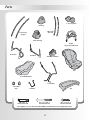
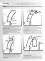
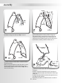
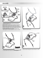
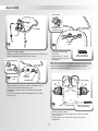
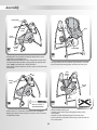
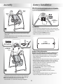
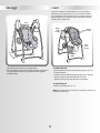
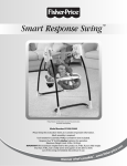
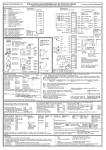
Smart Response Swing
™
Product features and decorations may vary from picture above.
Accessories sold separately.
Model Number: B2108, B3469, G5175
PLEASE KEEP FOR FUTURE REFERENCE.
Please read these instructions before assembly and use of this product, as they contain important information.
Adult assembly is required.
Tool needed for assembly: Phillips Screwdriver (not included).
Requires four “D” (LR20) alkaline batteries for operation.
Maximum Weight Limit: 24 lbs. (10.9 kg).
IMPORTANT! The maximum weight limit for this product is 24 lbs. If your child weighs
less than 24 lbs., but is really active and appears to be able to climb
out of the swing, immediately discontinue its use.
w
pr
r
e
sh
ww.fi
co
.
e
ic
m
Warnings and Caution
Consumer Information
Occasionally a consumer may experience a problem with
one of our products. If this should happen, please call us
toll-free, rather than return this product to the store. Usually,
we can solve the problem over the telephone or send you
replacement parts. Please call Fisher-Price® Consumer
Relations, toll-free at 1-800-432-5437, 8 AM - 6 PM EST
Monday through Friday. Hearing-impaired consumers using
TTY/TDD equipment, please call 1-800-382-7470.
WARNING
• To prevent serious injury or death
from falls and being strangled in
the restraint system:
- Always use the restraint system. Never rely on the tray to
restrain child.
- Never use with an active child
who may be able to climb out of
the seat.
• Never leave child unattended.
Or, write to:
Fisher-Price®
Consumer Relations
636 Girard Avenue
East Aurora, New York 14052
CAUTION
This product contains small parts
in its unassembled state.
Adult assembly is required.
2
Parts
2 Accessory Bins
Housing
2 Rear Legs
(Shorter)
2 Front Legs
(Longer)
Motor Housing
Toy Bar
(Toys may be different)
Front Base
Bracket
(with M4 Lock Nuts)
Rear Base
Pad
Seat with Restraint
2 Seat Tubes
2 Seat Wire
Caps
M4 Screw - 4
Shown Actual Size
Seat Wire
Tray
#8 x 13/8" Screw - 6
Shown Actual Size
#6 x 5/8" Screw - 8
Shown Actual Size
Note: Tighten or loosen all screws with a Phillips screwdriver. Do not over-tighten the screws.
3
Assembly
IMPORTANT! Before assembly, inspect this product for damaged hardware, loose joints, missing parts or sharp edges. DO NOT use
if any parts are missing or broken. Contact Fisher-Price® for replacement parts and instructions if needed. Never substitute parts.
Housing
Front Legs
(Longer)
Hub
Slot
Tapered End
Motor
Housing
Press
Buttons
Press
Button
Front
Legs
Press
Button
Tapered End
1
3
Front Base
• Position the housing so that the hub is inward.
• While pressing the button on the top of front leg, insert it
into the housing slot, as shown. Push the front leg until the
button “snaps” into the hole in the housing.
• Repeat this procedure to assemble the motor housing to
the other front leg.
• Pull the front legs down to be sure they are secure in the
housings. If you can remove them, you have not assembled
them correctly. Please re-read and repeat this assembly step.
• Place the front base on a flat surface.
• Position a front leg (longer) so that the tapered end is
downward, as shown.
• While pressing the button on one of the front legs, insert it
into the front base. Push down on the front leg until the
button “snaps” into the hole in the front base.
• Repeat this procedure to assemble the other front leg to
the front base.
Motor Housing
Short Tube
Button
Pull Up
Front Legs
Pull Up
Tapered
End
4
2
Front Base
• While standing on the front base, pull the front legs up.
The front legs should remain secured to the front base.
If you can remove the front legs, you have not assembled
them correctly to the front base. Reread and repeat
assembly step 1.
4
Rear Legs
• Position a rear leg so that the tapered end is upright.
• While pressing the button on the top of the rear leg, insert it
into the housing short tube, as shown. Push the rear leg
until the button “snaps” into the hole in the short tube.
• Repeat this procedure to assemble the other rear leg to the
motor housing short tube.
• Pull the rear legs down to be sure they are secure in the
housings. If you can remove them, you have not assembled
them correctly. Please re-read and repeat this assembly step.
Assembly
Pull Up
Pull Up
Pull
Rear
Leg
Pull
Rear
Leg
Rear Legs
5
7
• Pull both rear legs out until they “snap” into place.
Rear Base
• While standing on the rear base, pull the rear legs up.
They should remain secured to the rear base. If you can
remove the rear legs, you have not assembled them correctly to the rear base. Reread and repeat assembly step 6.
• Set the frame assembly aside for Assembly step 17.
Rear
Legs
Seat Tube
Long Ends
Press
Button
Press
Button
6
Front
Base
Rear Base
Ridges
• Place the rear base on a flat surface so that the buttons
face the front base.
• While pressing the buttons on each side of the rear base,
fit the rear legs onto the rear base. Push the rear legs
down until the buttons on the rear base “snap” into the
holes in each rear leg.
Curved
End
8
Top of Seat
5
• Position the seat face down, with the top of the seat
facing you.
• Position a seat tube so that the long end is upright and
toward you and the curved end is toward the outside edge
of the seat.
• Insert the curved end of the seat tube through the holes in
the ridges on the seat back.
• Repeat this procedure to assemble the other seat tube to
the seat.
Assembly
M4 Lock Nut
Rounded Side
Bracket
Grooves
Shown Actual Size
Tall
End
Lock Nut
Seat
Tubes
Bottom
Edge of
Seat
Hexagonal
Opening
9
• Position the bracket so that the tall end is toward the
bottom edge of the seat.
Hint: The M4 lock nuts have been assembled to the bracket at
the factory. During shipment of this product, they may have
fallen out. Check to be sure there is a lock nut in each hexagonal
opening on the bracket. If one (or more) has fallen out, fit the lock
nut into a hexagonal opening in the bracket. Make sure the
rounded side of the lock nut is facing up.
• Fit the grooves on the bracket to the seat tubes, as shown.
Seat
Tubes
11
• Rotate the seat tubes down.
Seat Wire
Seat Tubes
Bracket
Bracket
Slot
12
10
M4 Screw - 4
Shown Actual Size
• Fit the seat wire through the slot in the bracket as shown.
• Insert four M4 screws into the seat tubes and tighten.
6
Assembly
Press in Place
Seat Wire is
Through Hole in
Seat Wire Cap
Seat Wire
Slots
13
Seat Wire
Caps
15
• Lift the seat tubes slightly.
• With the seat wire hanging down, insert the ends of the seat
wire through the slots in the seat, as shown.
• Press the seat wire caps
into place.
• Insert two #6 x 5/8" screws
through each seat wire cap
and tighten.
Rounded Edge Up
#6 x 5/8" Screw - 4
Shown Actual Size
Hint: The seat wire caps are designed to fit into the seat only one
way. If the screw holes in the seat wire caps do not align with the
holes in the seat, try switching the seat wire caps onto the
opposite ends of the seat wire.
Seat Wire
Cap Hole
14 SeatCapWire
Ends of
Seat Wire
Accessory Bin
Seat Wire Cap
• While holding the seat wire in place, carefully turn the
seat around so that the front faces you.
• Position the seat wire cap so that the rounded edge
is upright.
• Fit each end of the seat wire through the hole in each
seat wire cap.
Accessory Bin
Grooves
16
Seat
#8 x 13/8” Screw - 4
Shown Actual Size
• Turn the seat face down.
• Fit an accessory bin into the groove on each side of the
seat, as shown.
• Insert two #8 x 13/8" screws into each accessory bin
and tighten.
7
Assembly
Frame Hub
Push
Button
Pad
Swing
Tube
Front
of Seat
Waist Belts
17
Curved
Front
Base
Crotch Belt
19
• Position the seat assembly so that the front of the seat is
toward the curved front base.
• While pressing the buttons on the swing tubes, insert them
into the frame hubs. Push the swing tubes up until the buttons “snap” into the hole in the frame hubs.
• Push down on the seat to be sure the seat is secured in both
frame hubs.
• Fit the pocket on the back of the pad onto the seat back.
• Fit the waist belts through the smaller slots in the pad.
Pad
Elastic
Loops
Frame
Hubs
Crotch
Belt
Holes
20
18
#8 x 1 /8” Screw - 2
Shown Actual Size
3
Seat Bottom
• Lift the bottom of the pad.
• Insert the pad elastic loops through the holes in the
seat bottom.
• Insert the crotch belt through the slot in the pad.
• From under the seat, fit the elastic loops onto the tabs on
the seat bottom.
• Insert a #8 x 13/8" screw into each frame hub and tighten.
• Again, push down on the seat to be sure the seat is secured
to both frame hubs.
8
Assembly
Battery Installation
Hint: When swinging, sound or power L.E.D. slows/dims/stops,
it’s time to replace the batteries! We recommend using alkaline
batteries for longer battery life.
Elastic
Loop
Elastic
Loop
Battery
Compartment
Door
Installation
21
• Locate the battery compartment door on the swing frame.
• Insert a coin into the battery compartment door and pry the
battery compartment door off of the swing frame.
• Insert four “D” (LR20) alkaline batteries.
• Replace the battery compartment door.
• Fit the bottom edge of the pad around the bottom edge
of the seat.
• Hook the elastic loops on each side of the pad to the peg on
the back of the accessory bins.
Hub
1.5V x 4
“D” (LR20)
SHOWN ACTUAL SIZE
#6 x /8” Screw - 4
Shown Actual Size
5
Plug
Toy Bar
(Toys may
be different)
Plug
Plug
Battery Safety Information
Socket
Batteries may leak fluids that can cause a chemical burn
injury or ruin your product. To avoid battery leakage:
• Do not mix old and new batteries or batteries of different
types: alkaline, standard (carbon-zinc) or rechargeable
(nickel-cadmium).
• Insert batteries as indicated inside the battery compartment.
• Remove batteries during long periods of non-use. Always
remove exhausted batteries from the product. Dispose of
batteries safely. Do not dispose of batteries in a fire.
The batteries may explode or leak.
• Never short-circuit the battery terminals.
• Use only batteries of the same or equivalent type,
as recommended.
• Do not charge non-rechargeable batteries.
• Remove rechargeable batteries from the product
before charging.
• If removable, rechargeable batteries are used, they are
only to be charged under adult supervision.
22
• Fit the toy bar plugs into the sockets on the swing tubes.
Hint: If the toy bar plugs do not fit into the sockets, turn the
toy bar around. Now, fit the plugs into the sockets.
• Insert two #6 x 5/8" screws into each plug and tighten.
9
Securing Your Child
IMPORTANT! Before each use, inspect this product for
damaged hardware, loose joints, missing parts or sharp
edges. DO NOT use if any parts are missing or broken. Contact
Fisher-Price® for replacement parts and instructions if
needed. Never substitute parts.
B
B
WARNING
• To prevent serious injury or death
from falls and being strangled in the
restraint system:
- Always use the restraint system. Never rely on the tray to
restrain child.
- Never use with an active child
who may be able to climb out of
the seat.
• Never leave child unattended.
Waist
Belt
Waist
Belt
Crotch
Belt
1
• Place your child in the seat. Position the crotch belt between
your child’s legs.
• Fasten both waist belts to each side of the crotch belt. Make
sure you hear a “click” on both sides.
• Check to be sure the restraint system is securely attached by
pulling it away from your child. The restraint system should
remain attached.
10
2
Tighten
Loosen
To tighten the restraint:
• Feed the anchored end of the waist belt up through the
buckle to form a loop . Pull the free end of the waist
belt B .
To loosen the restraint:
• Feed the free end of the waist belt up through the buckle to
form a loop
. Enlarge the loop by pulling on the end of
the loop toward the buckle. Pull the anchored end of the
waist belt to shorten the free end of the waist belt B .
Note: After adjusting the restraint to fit your child, make sure
you pull on it to be sure it is securely fastened.
Adjusting the Seat
Using the Toy Bar
Toy Bar
Upright
Semi-Recline
3
Recline
Adjust the seat angle in any of three positions: Upright,
Semi-Recline or Recline.
To adjust the seat angle: Push down on the seat back to
position the seat wire in the desired groove in the bracket
for Upright, Semi-Recline or Recline.
5
• Lift or lower the toy bar for baby's enjoyment.
Using the Tray
Tray
4
• Fit the tray onto the seat armrests.
11
Swing Modes
The Smart Response™ Swing has two modes: Baby Sounds Activated
and Parent Activated
.
Product features and decorations may vary from pictures below.
Accessories sold separately.
Parent Activated
Baby Sounds Activated
IMPORTANT! The maximum weight limit for this product is 24 lbs. If your child weighs less than 24 lbs., but is really active and
appears to be able to climb out of the swing, immediately discontinue its use.
12
Baby Sounds Activated
Product features and decorations may vary from picture below.
Accessories sold separately.
Speed Dial
Sound Sensitivity Dial
Power
L.E.D.
Swing Mode Switch
Music/Volume Switch
Sound Sensitivity Dial
• Slide the switch to
high sensitivity for incoming
sounds (listens for shallow sounds).
• Slide the switch to
low sensitivity for incoming sounds
(listens only for loud sounds).
Swing Mode Switch
• Slide the switch to
baby sounds activated. The
power L.E.D. lights. The swing begins swinging for about
15-20 minutes and if you have selected music, five songs
play (about 15-20 minutes). After swinging (and music) stop,
the swing is ready to listen for your baby’s sounds for about
two hours.
• When baby cries, the swing (and music, if selected) automatically turns on to soothe baby.
• If the swing is not activated (from baby’s sounds) within two
hours of selection, the power L.E.D. flashes to tell you that it
going to turn off. Once it has turned off (and the power
L.E.D. is not lit), you will need to slide the switch to the off
position
and back to
baby sounds activated. The
swing is now re-set to listen for your baby’s sounds for
another two hours.
• Be sure to turn the product off
when not in use.
Hint: You may want to start with the high sensitivity setting
at first.
Music/Volume Switch
• Select
for music highest volume.
• Select
for music high volume.
• Select
for music low volume.
• Select to turn music off.
Speed Dial
• Select any of five speed settings.
Hint: As with most battery-powered swings, a heavier
child will reduce the amount of swinging motion on all settings. In most cases, the low setting works best for a smaller
child while the high setting works best for a larger child.
13
Parent Activated
Product features and decorations may vary from picture below.
Accessories sold separately.
Power
L.E.D.
Swing Mode Switch
Speed Dial
Music/Volume Switch
Swing Mode Switch
• Slide the switch to
parent activated. The power L.E.D.
lights and the swing begins swinging.
• Be sure to turn the product off when not in use.
Speed Dial
• Select any of five speed settings.
Music/Volume Switch
• Select
for music highest volume.
• Select
for music high volume.
• Select
for music low volume.
• Select to turn music off.
Hint: As with most battery-powered swings, a heavier
child will reduce the amount of swinging motion on all settings. In most cases, the low setting works best for a smaller
child while the high setting works best for a larger child.
14
Storage
Care
The pad is machine washable. Wash the pad separately in
cold water on the gentle cycle. Do not use bleach. Tumble
dry separately on low heat and remove promptly. The frame,
tray, and toybar may be wiped clean using a mild cleaning
solution and a damp cloth.
Press
Buttons
Upper
Pad
Pocket
Toy Bar
Elastic
Loops
Lower
Pad
Pocket
Elastic
Loops
Restraint
Belts
• Turn the toy bar back to it's storage position.
• Press the button on the inside of each housing and push the
rear legs toward the front legs. Stand the frame against a
wall for storage.
To remove the pad:
• Unhook the four elastic hooks from the pegs on the seat
back and bottom.
• Push the restraint belts back through the slots in the pad.
• Slide the upper pad pocket off of the seat back.
• Slide the lower pad pocket off of the seat bottom.
To replace the pad:
• Refer to Assembly steps 19 - 21.
Note: This product has no consumer serviceable parts. Do not
take this product apart.
15
One (1) Year Limited Warranty
FCC Statement (United States Only)
Fisher-Price, Inc., 636 Girard Avenue, East Aurora, New York
14052 warrants that Smart Response™ Swing is free from
all defects in material and workmanship when used under
normal conditions for a period of one (1) year from the date
of purchase.
Should the product fail to perform properly, we will repair or
replace it at our option, free of charge. Purchaser is responsible for shipping the product to Consumer Relations at the
address indicated above and for all associated freight and
insurance cost. Fisher-Price, Inc. will bear the cost of shipping
the repaired or replaced item to you. This warranty is void if
the owner repairs or modifies the product. This warranty
excludes any liability other than that expressly stated above
including but not limited to any incidental or consequential
damages.
SOME STATES DO NOT ALLOW THE EXCLUSION OR LIMITATION
OF INCIDENTAL OR CONSEQUENTIAL DAMAGES, SO THE
ABOVE LIMITATION OR EXCLUSION MAY NOT APPLY TO YOU.
THIS WARRANTY GIVES YOU SPECIFIC LEGAL RIGHTS, AND
YOU MAY ALSO HAVE OTHER RIGHTS WHICH MAY VARY FROM
STATE TO STATE.
This equipment has been tested and found to comply with
the limits for a Class B digital device, pursuant to part 15 of
the FCC rules. These limits are designed to provide reasonable
protection against harmful interference in a residential installation. This equipment generates, uses and can radiate radio
frequency energy and, if not installed and used in accordance
with the instructions, may cause harmful interference to radio
communications. However, there is no guarantee that interference will not occur in a particular installation. If this equipment does cause harmful interference to radio or television
reception, which can be determined by turning the equipment off and on, the user is encouraged to try to correct the
interference by one or more of the following measures:
Reorient or relocate the receiving antenna.
Increase the separation between the equipment and receiver.
Connect the equipment into an outlet on a circuit different
from that to which the receiver is connected.
Consult the dealer or an experienced radio/TV technician
for help.
Note: Changes or modifications not expressly approved by
the manufacturer responsible for compliance could void the
user's authority to operate the equipment.
For other countries outside the United States:
Canada: call 1-800-567-7724, or write to: Mattel Canada Inc., 6155 Freemont
Blvd., Mississauga, Ontario L5R 3W2.
Great Britain: telephone 01628 500302.
Australia: Mattel Australia Pty. Ltd., 658 Church Street, Locked Bag #870,
Richmond, Victoria 3121 Australia. Consumer Advisory Service 1300 135 312.
New Zealand: 16-18 William Pickering Drive, Albany 1331, Auckland.
Asia: Mattel East Asia Ltd, Room 1106, South Tower, World Finance Centre,
Harbour City, Tsimshatsui, HK, China.
Fisher-Price, Inc., a subsidiary of Mattel, Inc., East Aurora, NY 14052 U.S.A.
©2003 Mattel, Inc. All Rights Reserved. ® and ™ designate U.S. trademarks of Mattel, Inc.
Printed in China
B2108c-0920