1
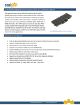
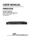
USER’S MANUAL Universal PCI RS-232 Communication Board English Version Second Edition, March 2014 SUNIX Co., Ltd. Tel : +886-2-8913-1987 Fax: +886-2-8913-1986 Http://www.sunix.com [email protected] ___________________________________________________________________________________ Universal PCI RS-232 Communication Board User’s Manual Copyright Copyright© 2014 SUNIX Co., Ltd. All Rights Reserved. No part of this publication may be reproduced, transcribed, stored in a retrieval system, translated into any language, or transmitted in any from or by any means, photocopying, manual, or otherwise, without prior written permission from SUNIX. Disclaimer SUNIX shall not be liable for any incidental or consequential damages resulting from the performance or use of this equipment. SUNIX makes no representations or warranties regarding the contents of this manual. Information in this manual has been carefully checked for reliability; however, no guarantee is given as to the correctness of this content. In the interest of continued product improvement, this company reserves the right to revise the manual or include change in the specifications of the product described within it at any time without notice and without obligation to notify any person of such revision or changes. The information contained in this manual is provided for general use by the customers. Trademarks SUNIX is a registered trademark of SUNIX Group. All other trademarks or registered marks in this manual belong to their respective owners. Safety Information 1. Keep this User’s Manual for future reference. 2. Always read the safety information carefully. 3. Keep this equipment away from direct sunlight, or in humid or damp places. 4. Do not place this equipment in an unstable position, or on vibrating surface before setting it up. 5. Do not use or place this equipment near magnetic fields, televisions, or radios to avoid electronic interface that affects device performance. 1 ___________________________________________________________________________________ Regulatory Compliance FCC Conditions This equipment has been tested and found to comply with Part 15 of the FCC Rules. Operation is subject to the following two conditions: (1) This equipment may not cause harmful interference (2) This equipment must accept any interference received, including interference that may cause undesired operation. Important! Changes or modifications not expressly approved by the manufacturer responsible for compliance could void the user’s authority to operate the equipment. Use an approved phone set. CE This equipment is in compliance with the requirements of the following regulations: EN 55022: CLASS B WEEE Information For EU (European Union) member users: According to the WEEE (Waste electrical and electronic equipment) Directive, do not dispose of this product as household waste or commercial waste. Waste electrical and electronic equipment should be appropriately collected and recycled as required by practices established for your country. For information on recycling of this product, please contact your local authorities, your household waste disposal service or the shop where you purchased the product. 2 ___________________________________________________________________________________ Table of Contents Chapter 1 Introduction 1.1 Overview ..................................................................................................................... 6 1.2 Package Checklist....................................................................................................... 6 1.3 Product Features......................................................................................................... 7 1.4 Product Specifications ................................................................................................. 8 Chapter 2 Hardware Installation 2.1 Hardware Installation ................................................................................................ 10 2.2 Pin Assignment ......................................................................................................... 11 Chapter 3 Software Installation 3.1 Windows Driver Installation ....................................................................................... 15 3.2 Windows Driver Uninstallation................................................................................... 20 3.3 Linux Driver Installation ............................................................................................. 21 3.4 Verify Installation ....................................................................................................... 23 Chapter 4 Port Configuration 4.1 Configure Serial Port Settings ................................................................................... 25 4.2 Com Port Number Settings ....................................................................................... 26 4.3 Com I/O Resource .................................................................................................... 26 4.4 FIFO Settings ............................................................................................................ 27 4.5 Advanced Settings .................................................................................................... 28 Chapter 5 Appendix 5.1 Troubleshooting ........................................................................................................ 30 5.2 Product Family .......................................................................................................... 32 5.3 Contact Information ................................................................................................... 37 3 ___________________________________________________________________________________ WHQL Certification Approval The Designed for Microsoft Windows 32/64-bit operation system WHQL logo identifies products that meet Microsoft’s quality standards, SUNIX I/O products carry with this logo and listed on Windows Catalog. WHQL logo includes below operation system version Microsoft Windows Client: Windows XP / Vista / 7 / 8 / 8.1 (X86/X64) Microsoft Windows Server: Windows 2003 / 2008 / 2012 (X64) 4 ___________________________________________________________________________________ 1. Introduction ______________________________________________ RS-232 Golden I/O series, a line of Universal PCI Multi-port Serial Communication Board, is designed for both 3.3V / 5V and 32 / 64-bit PCI Bus with Plug and Play feature. It can be installed in virtually any available PC system and compatible with all major operating systems. Users do not need to manually set jumpers to configure I/O addresses and IRQ locations. These boards offer independent serial ports for connecting terminals, modems, printers, scanners, cash registers, bar code readers, keypads, numeric displays, electrical scales, data acquisition equipment, and other serial devices for the PC and compatible systems. This board offers a reliable and high performance solution for serial multi-port communications. The following topics covered in this chapter: 1.1 Overview 1.2 Package Checklist 1.3 Product Features 1.4 Product Specifications 5 ___________________________________________________________________________________ 1.1 Overview Thanks for purchasing SUNIX Universal PCI Multi-Port Communication Board; it is compatible with RS-232.V24 standard serial interfaces. User can expand Multi RS-232 ports on PC-based system by installing in PCI or PCI-X slots. Each port has on-chip hardware and software flow control, a built-in 128-byte Tx/Rx FIFO, and WHQL certificated device drivers. This board is designed with SUNIX 16C950 UART controller and as well built with many of SUNIX advanced features and technologies, making it the best solution for commercial and industrial automation applications. 1.2 Package Checklist Please check if the following items are present and in good condition upon opening your package. Contact your vendor if any item is damaged or missing. 1. Hardware: Serial Communication Board: RS-232 Universal PCI Multi-Port Communication Board × 1 Cable: (Depend on what product you bought) * 4 ports PCI series: DB44M to 4 ports DB9/25 Male Cable × 1 * 8 ports PCI series: DB62M to 8 ports DB9/25 Male Cable × 1 2. CD Driver 3. Quick Installation Guide 4. User's Manual (This document) 6 ___________________________________________________________________________________ 1.3 Product Features Expands Multi RS-232 serial ports on the system High performance SUNIX 16C950 compatible UART controller on-board. Ultra low power consumption design for Green Environment. Compliance with PCI 33MHz Version 3.0/2.3/2.2./2.1 specification. Supports both 64-bit PCI-X & 32-bit PCI bus slot. Data transmission speeds up to 115.2Kbps (921.6Kbps Optional). On-chip hardware auto flow control to guarantee no data loss. Built-in ± 2KV ESD protection for all serial signals. (± 15KV ESD Optional) Plug-n-Play, I/O address and IRQ assigned by BIOS. Certified by CE, FCC, RoHS, and Microsoft WHQL approval. Support Microsoft Windows, Linux, and DOS. Note: SUNIX High Speed RS-232 Card (H Version) supports ± 15KV ESD protection for each signal and 921.6Kpbs baud rate setting. Please refer to the Chapter 5 Appendix, Product Family for detail. 7 ___________________________________________________________________________________ 1.4 Product Specifications Serial Communication Interface Controller BUS No. of Port IRQ & IO FIFO Protection RS-232 Signal SUNIX SUN1999 (16C950 UART Compatible) Universal PCI 64/32bit PCI Spec.Ver3.0/2.3/2.2/2.1 1/2/4/8/16-port Baud rate Stop bit TxD, RxD, RTS, CTS, DTR, DSR, DCD, RI, GND 50bps ~115.2Kbps (921.6Kpbs Optional) 1, 1.5, 2 Parity even, odd, none, mark, space Flow Assigned by System None, Xon/Xoff, RTS/CTS Control 128byte Hardware Connector DB9 / 25 Male ±2KV ESD protection for each signal Human Body Model (HBM) (±15KV ESD Optional) Driver Support Windows Client XP / Vista / 7 / 8 / 8.1 (X86/X64) Windows Server 2003 / 2008 / 2012 (X64) Microsoft Embedded XP Embedded / POS Ready 2009 / Embedded System 2009 Linux Linux 2.4.x / 2.6.x / 3.x DOS DOS FreeBSD FreeBSD 5.3~5.5 / 6.0~6.4 QNX QNX 6.3.2 / 6.4.0 IBM OS/2* WARP 3 / WARP 4 SCO UnixWare* UnixWare 7.1.3 / 7.1.4 Open Server 5.0.7 / 6.0 Sun Microsystems* Solaris 10 Note : “ * “ Supported by special inquiry. Regulatory Approvals Hardware Software EN55022 Class B, EN55024, EN61000-3-2, EN61000-3-3, FCC Part 15 Class B, RoHS Microsoft WHQL Windows Microsoft Client: XP / Vista / 7 / 8 / 8.1 (X86/X64) Microsoft Server: 2003 / 2008 / 2012 (X64) Environment Operation Temperature Operation Humidity Storage Temperature 0 to 60°C (32 to 140°F) 5 to 95% RH -20 to 85°C (-4 to 185°F) 8 ___________________________________________________________________________________ 2. Hardware Installation ______________________________________________ This chapter includes information about hardware installation for RS-232 Universal PCI Multi-Port Communication Board. The following topics are covered: 2.1 Hardware Installation 2.2 Pin Assignments 9 ___________________________________________________________________________________ 2.1 Hardware Installation The hardware installation of PCI serial boards is easy to carry out. Before inserting the card into the PCI bus, please follow the detailed steps given below to install the PCI serial board in your computer. Safety First To avoid damaging your system and boards, make sure your PC’s power is turned off before installing PCI card. Step 1: Turn your PC’s power off, and shut off the power to any peripheral. Step 2: Remove the power plug from the plug socket. Step 3: Remove the cover from the computer case. Step 4: If fitted. Remove the metal cover plate on the rear of a free PCI slot. Step 5: Insert Universal PCI Multi-Port Communication Board into the free PCI slot and screw it firmly on the bracket side. Step 6: Place the cover back onto the computer. Step 7: Insert the plug into the plug socket. 10 ___________________________________________________________________________________ 2.2 Pin Assignment This chapter provides the pin assignments for SUNIX Universal PCI Multi-Port Communication Board, as well as the pin assignments for the optional accessories. PIN DCD RxD TxD DTR GND DSR RTS CTS RI DB9M 1 2 3 4 5 6 7 8 9 DB25M 8 3 2 20 7 6 4 5 22 RJ45 7 6 3 2 4 8 1 5 - Pin Header 1 3 5 7 9 2 4 6 8 Note: 8-port RS-232 card product series does not build the 9th pin RI signal. 11 ___________________________________________________________________________________ SUNIX 2-port RS-232 Low Profile Card builds DB44F connector on board. SUNIX DB44 Female 2 ports Serial Communication Boards Pin Assignment Port 1 2 TxD 11 15 RxD 40 44 RTS 10 14 CTS 39 43 DSR 38 42 GND 25 29 DCD 26 30 DTR 9 13 RI 24 28 Signal RS-232 SUNIX 4-port RS-232 Card builds DB44F connector on board. SUNIX DB44 Female 4 ports Serial Communication Boards Pin Assignment Port 1 2 3 4 TxD 3 7 11 15 RxD 32 36 40 44 RTS 2 6 10 14 CTS 31 35 39 43 DSR 18 34 38 42 GND 4 21 25 29 DCD 17 22 26 30 DTR 1 5 9 13 RI 16 20 24 28 Signal RS-232 12 ___________________________________________________________________________________ SUNIX 8-port RS-232 Card builds DB62F connector on board. SUNIX DB62 Female 8 ports Serial Communication Boards Pin Assignment Port 1 2 3 4 5 6 7 8 DCD 24 45 8 50 11 55 58 21 RxD 44 47 49 52 54 57 60 62 TxD 23 26 28 31 34 36 39 41 DTR 2 5 7 10 13 15 18 20 DSR 1 4 6 9 12 14 17 19 RTS 22 25 27 30 33 35 38 40 CTS 43 46 48 51 53 56 59 61 Signal RS-232 GND GND GND GND GND GND GND GND GND SUNIX 8-port RS-232 Low Profile Card builds DB68F connector on board. SUNIX DB68 Female 8 ports Serial Communication Boards Pin Assignment Port Signal RS-232 1 2 TxD 6 15 24 33 63 54 45 36 RxD 3 12 21 30 66 57 48 39 RTS 7 16 25 34 62 53 44 35 CTS 4 13 22 31 65 56 47 38 DSR 2 11 20 29 67 58 49 40 GND 8 9 DCD 1 10 19 28 68 59 50 41 DTR 5 14 23 32 64 55 46 37 RI - - 3 4 5 6 7 8 26 27 61 60 43 42 - - 13 - - - - ___________________________________________________________________________________ 3. Driver Installation ______________________________________________ After installing the RS-232 Universal PCI Multi-Port Communication Board in your system successfully, please follow the step by step software installation guide to confirm how to install appropriate driver and configure the serial port settings. The driver for PCI serial board supports Windows and Linux operating systems, and you can select your requirement in the following chapter: The following topics covered in this chapter: 3.1 Windows Driver Installation 3.2 Windows Driver Uninstallation 3.3 Linux Driver Installation 3.4 Verify Installation 14 ___________________________________________________________________________________ 3.1 Windows Driver Installation Please refer to following instructions to install the driver for the first time under Windows operation system. You will need to plug the board in an available PCI or PCI-X slot first, before installing the driver. (1) After the board is physically installed and the PC boots up, system will detect the PCI Serial card and prompt for driver installation wizard, please choose cancel. (2) Put CD driver bound with product in your CD / DVD ROM drive. Please select autorun.exe., then select “Driver Installation”. 15 ___________________________________________________________________________________ (3) Please select the product interface you bought, such as PCI. (4) Please select the O.S. version you are using, such as Windows 8. Then system will process the driver installation step automatically. 16 ___________________________________________________________________________________ (5) Please select driver language for your operation system. (6) Click “Next” to continue driver installation steps. 17 ___________________________________________________________________________________ (7) Click “Install” to continue driver installation steps. (8) System will install driver automatically. It takes about one minute. 18 ___________________________________________________________________________________ (9) Click “Finish” to end installation steps. 19 ___________________________________________________________________________________ 3.2 Windows Driver Uninstallation Please refer to following instructions uninstall Multi-I/O card driver. (1) Click on the “Programs and Features” tab in the Windows Control Panel. Start > Controller Panel > Programs and Features (2) Entry Uninstall or change a program page, and double click “Windows Driver Package – SUNIX Co., Ltd SUNIX Multi-I/O Controller” to process driver uninstallation procedure. 20 ___________________________________________________________________________________ 3.3 Linux Driver Installation This installation guide describes the procedures to install the PCI serial board in Linux kernel 2.4.x and 2.6.x. Please refer to “snx_Vx.x.x.x.tar.gz” for driver installation detail in CD Driver (Linux folder) directory. : \ PCI_IO \ Linux (1) Driver install Please create a directory under root directory, e.g /temp, do commands: # cd / # mkdir temp After get driver file "snx_Vx.x.x.x.tar.gz". Copy file to /temp directory, then extract and install, do commands: # cp snx_Vx.x.x.x.tar.gz /temp # cd /temp # tar xvfz snx_Vx.x.x.x.tar.gz # cd /temp/snx # make clean ; make install ************************************************************* * If system is Suse 9.0 and errors occur when * "make clean ; make install", do commands: * * # cd /usr/src/linux/ * # make cloneconfig * # make dep * * then do "make clean ; make install" again in /temp/snx ************************************************************* 21 ___________________________________________________________________________________ Load driver module, do command: # modprobe snx or # insmod /temp/snx/driver/snx.ko (snx.o for kernel 2.4) Check driver module, do command: # lsmod | grep snx Unload driver, do command: # rmmod snx (2) Device node creation Each serial port has one device node which is named "ttySNX?", maximum up to 32 serial ports. Each parallel port has two device node which is name "lp?" and "parport?". This step will backup lp2~lp3 and parport2~parport3 to lp?.bak and parport?.bak in /dev for your system first. Then, create lp2~lp3 and parport2~parport3 in /dev for sunix driver, maximum up tp 2 parallel ports. This setp will be done when do "make clean ; make install", if device nodes aren't in /dev, do commands: # cd /temp/snx/snxmknod # ./snxmknod This will create device nodes in /dev. If there are more than two boards installed, serial port device nameing convention please refer to F1. 22 ___________________________________________________________________________________ 3.4 Verify Installation You can use Windows “Device Manager” to verify proper installation. (1) Click on the “Programs and Features” tab in the Windows Control Panel. Start > Controller Panel > Device Manager (2) In the Device Manager window, you should see this board under Multifunction adapters (4-port RS-232 Serial Card in this example). You should also see SUNIX COM port under Ports (COM & LPT). 23 ___________________________________________________________________________________ 4. Port Configuration ______________________________________________ This chapter shows all Serial COM port settings that user came with usually, such as COM port number, FIFO length(size), baud rate, IO address and others. The following topics covered in this chapter: 4.1 Configure Serial Port Settings 4.2 COM Port Number Settings 4.3 COM I/O Resource 4.4 FIFO Settings 4.5 Advanced Settings 24 ___________________________________________________________________________________ 4.1 Configure Serial Port Settings After the board and serial port drivers are installed, please refer to following instructions to configure Serial COM settings. (1) Please launch the “Device Manager”. (2) Right click the “SUNIX Serial Card” item from the “Multifunction adapters” sub-tree and click “Properties”. (3) On the “Port Control” tab, select a port to configure. * Click “OK” to approve the settings for the selected port. * Click “Set to All” to approve the settings for all COM ports. 25 ___________________________________________________________________________________ 4.2 COM Port Number Settings Under Port Number, select a COM number to assign to the serial port. Click “OK” to approve the settings for the selected port. Note: In order to prevent system resource conflict, do not select “in use” port. 4.3 COM I/O Resource User can read the COM “IO Range” and “IRQ” located in system by selecting COM port. IRQ and I/O address is automatically assigned by the mainboard PCI BIOS automatically (before COM card driver installing). User can NOT assign legacy ISA address (3F8, 3E8, 2F8, 2E8) for the specific COM port. But for IRQ setting, user can set specific IRQ value for this PCI bus slot via mainboard’s BIOS settings (not via SUNIX driver). But all COM ports will share one IRQ value. 26 ___________________________________________________________________________________ 4.4 FIFO Settings Select an Rx FIFO Trigger and Tx FIFO Size. The default Rx FIFO Trigger is 112 bytes. The default Tx FIFO Size is 128 bytes. Click “Set to All” to change this setting for all serial ports on the board. Then click “OK” to save the settings. Receive FIFO interrupt trigger level: When the level of data in the receiver FIFO reaches this value, a receiver data interrupt is triggered. Transmit FIFO interrupt trigger level: When the level of data in the transmit FIFO falls below this value, a transmitter interrupt is triggered. Setting this value to zero will not trigger an interrupt until the transmitter is completely idle. The FIFO trigger levels can be fine tuned to gain optimum performance, depending on system performance, baud rate used, levels of serial traffic etc. 27 ___________________________________________________________________________________ 4.5 Advanced Settings User can control RS-232 communication in Advanced Port Control page through “Advanced” settings. Clock Rate This is the “Data Rate" value for on board crystal frequency of input clock. The baud rate can optionally be adjusted according to the data rate required. The clock pre-divisor is used to divide the input clock prior to baud rate generation. This parameter must matches with the oscillator (crystal) frequency on the board. System default is 14745600 Hz. We do NOT recommend for modification without SUNIX instruction. User can click “Defaults” button back to manufactory settings. 28 ___________________________________________________________________________________ 5. Appendix ______________________________________________ This chapter shows some problems that user came with usually. Also you can check it if the PCI serial board can not work properly in your system after following hardware and software installation steps. In addition, you could contact with us for detail technical product information. In this appendix, we cover the following topics. 5.1 Troubleshooting 5.2 Product Family 5.3 Contact Information 29 ___________________________________________________________________________________ 5.1 Troubleshooting 1. System fails to find the PCI serial board or COM port. A: It may cause by following issue: a. The board is not properly plugged into the PCI slot. b. Please clean the golden finger. c. The PCI slot is defective. Please try other slots until you find one that works. d. The mainboard does not have an available IRQ for the PCI serial board. Enter the PC.s BIOS and make sure an IRQ setting is available in the PCI/PnP settings. e. The board itself might be defective. You can try another mainboard testing this board working or not. 2. There is a blue screen when I entry operation system. A: a.The possible reason is an IRQ or I/O address conflict with other PCI bus adapters, such as LAN or serial boards, or with the system BIOS. Refer to the corresponding problem in the previous FAQ for solutions. b. Please check driver update from your vendor. 3. There are some exclamation marks in device manager and serial ports can not work properly. A: a.It caused by the wrong driver installing or hardware settings. Please turn off your computer firstly and re-install hardware and software, especially re-install the correct driver. b. Please update driver manually by specifying driver INF file folder. 4. Should I enable auto flow control features? A: Enable Auto CTS/RTS Flow Control means the CTS/RTS flow control is controlled by hardware automatically. System will be more stable if the function is enabled. Please make sure your serial device and cable wiring before enabling the hardware flow control function. 30 ___________________________________________________________________________________ 5. How large FIFO length I should set? A: FIFO (First-in-First-out) buffers are used to reduce the frequency of interrupt processes for UART chips. The size of the buffer will determines the number of times the cards need to interrupt the computer’s CPU in order to process a string of data. With larger FIFO buffer size; there is more data flow and less interruption to the CPU, therefore allowing the CPU to be free to handle other more crucial tasks. Set the Receive/Transmit Buffer to higher value will get faster performance because the interrupts will be reduced, but the time for interrupt service routine will become shorter. The receive buffer overflow will be easily happened if the CPU speed is not enough to handle. If the system is not stable, select the lower value to correct problems. 31 ___________________________________________________________________________________ 5.2 Product Family SUNIX provides kinds of RS-232/422/485 interface cards for customer selection, including PCI Express, PCI, PCI/104, CardBus, and ExpressCard. Please refer to the product family table for reference. RS-232 PCI Express Interface Port Connecter Baud Rate 16 Mini SCSI 68 Female 921.6Kbps DB62 Female 115.2 kbps ESD Protection Power output Bracket - Standard SER1640A - Standard SER5466A - Low profile SER5466AL - Standard SER5466H - Low profile SER5466HL Model NO. 8 Mini SCSI 68 Female 921.6Kbps - SER6456A Standard 5V/12V SER6456P 115.2 kbps - SER6456AL Low profile 5V/12V 4 SER6456PL DB44 Female - SER6456H Standard 5V/12V 921.6Kbps SER6456PH ±15KV - SER6456HL Low profile 5V/12V SER6456PHL DB9 Male SER6437A Standard 5V/12V SER6437P 115.2 kbps DB44 Female SER6437AL Low profile 5V/12V 2 SER6437PL DB9 Male SER6437H Standard 921.6Kbps 5V/12V SER6437PH - SER6437HL DB44 Female 5V/12V 5x2 Pin Header - 32 Low profile SER6437PHL SER6437UHL ___________________________________________________________________________________ RS-232 PCI Interface Port Connecter Mini SCSI 68 DB62 Female Mini SCSI 68 8 Baud Rate ESD Protection Power output 921.6Kbps ±15KV 115.2Kbps ±2KV - 5x2 Pin Header DB62 Female Mini SCSI 68 921.6Kbps ±15KV 5x2 Pin Header DB44 Female 115.2Kbps ±2KV 5x2 Pin Header 4 DB44 Female 921.6Kbps ±15KV 5x2 Pin Header DB44 Female DB9 Male 5x2 Pin Header 115.2Kbps ±2KV DB44 Female 2 5x2 Pin Header DB9 Male 5x2 Pin Header 921.6Kbps ±15KV DB44 Female 5x2 Pin Header 115.2Kbps 1 ±2KV DB9 Male 921.6Kbps ±15KV 5V/12V 5V/12V 5V/12V 5V/12V 5V/12V 5V/12V 5V/12V 5V/12V 5V/12V 5V/12V 5V/12V 5V/12V 33 Bracket Model NO. Standard Standard Low profile Standard Low profile Standard Low profile Standard Low profile SER1600A SER5066A SER5066AL SER5066U SER5066UL SER5066H SER5066HL SER5066UH SER5066UHL SER5056A SER5056P SER5056AL SER5056PL SER5056U SER5056UL SER5056H SER5056HL SER5056PH SER5056UH SER5056UHL SER5056PHL SER5037A SER5037P SER5037U SER5037AL SER5037PL SER5037UL SER5037H SER5037PH SER5037UH SER5037HL SER5037PHL SER5037UHL SER5027A SER5027P SER5027AL SER5027PL SER5027H SER5027PH SER5027HL Standard Low profile Standard Low profile Standard Low profile Standard Low profile Standard Low profile Standard Low profile Standard Low profile Standard Low profile SER5027PHL ___________________________________________________________________________________ RS-232 ExpressCard Interface Port Connecter Baud Rate ESD Protection 4 Bracket Model NO. 34mm ECS4000 34mm ECS2000 34mm ECS1000 DB44 Female 2 1 ±15KV 921.6Kbps DB9 Male RS-232 CardBus Interface Port Connecter Baud Rate ESD Protection 4 Bracket Model NO. 54mm CBS4000 54mm CBS2000 54mm CBS1000 DB44 Female 2 1 ±15KV 115.2Kbps DB9 Male RS-232 PCI/104 Interface Port Connecter Baud Rate ESD Protection 8 4 Model NO. SER5337A 5x2 Pin Header ±2KV 115.2Kbps 2 SER5356A SER5366A 34 ___________________________________________________________________________________ RS-422/485 PCI Express Interface Port Connecter Baud Rate ESD Protection 8 DB44 Female 921.6Kbps ±15KV 4 DB44 Female 921.6Kbps ±15KV 2 DB9 Male 921.6Kbps ±15KV Surge Protection Isolation Protection 600W 2.5KV - - 600W 2.5KV - - 600W 2.5KV - - Model NO. IPC-E2108SI IPC-E2108 IPC-E2104SI IPC-E2104 IPC-E2102SI IPC-E2102 RS-422/485 PCI Interface Port Connecter Baud Rate ESD Protection Surge Protection Isolation Protection 16 DB79 Female 921.6Kbps ±15KV - - 8 DB44 Female 921.6Kbps ±15KV 600W 2.5KV - - 4 DB44 Female 921.6Kbps ±15KV 600W 2.5KV - - 2 DB9 Male 921.6Kbps ±15KV 600W 2.5KV - - Surge Protection Isolation Protection 600W 2.5KV - - 600W 2.5KV - - 600W 2.5KV - - Model NO. IPC-P2116 IPC-P2108SI IPC-P2108 IPC-P2104SI IPC-P2104 IPC-P2102SI IPC-P2102 RS-422/485 PCI/104 Interface Port Connecter Baud Rate ESD Protection 8 5x2 Pin Header 921.6Kbps ±15KV 4 5x2 Pin Header 921.6Kbps ±15KV 2 5x2 Pin Header 921.6Kbps ±15KV 35 Model NO. IPC-B2108SI IPC-B2108 IPC-B2104SI IPC-B2104 IPC-B2102SI IPC-B2102 ___________________________________________________________________________________ RS-232/422/485 PCI Express Interface Port Connecter Baud Rate ESD Protection 8 DB44 Female 921.6Kbps ±15KV 4 DB44 Female 921.6Kbps ±15KV Surge Protection Isolation Protection 600W 2.5KV - - 600W 2.5KV - - Surge Protection Isolation Protection 600W 2.5KV - - 600W 2.5KV - - Model NO. IPC-E3108SI IPC-E3108 IPC-E3104SI IPC-E3104 RS-232/422/485 PCI Interface Port Connecter Baud Rate ESD Protection 8 DB44 Female 921.6Kbps ±15KV 4 DB44 Female 921.6Kbps ±15KV 36 Model NO. IPC-P3108SI IPC-P3108 IPC-P3104SI IPC-P3104 ___________________________________________________________________________________ 5.3 Contact Information Customer satisfaction is our number one concern, and to ensure that customers receive the full benefit of our products, SUNIX services has been set up to provide technical support, driver updates, product information, and user’s manual updates. The following services are provided E-mail for technical support ................................................ [email protected] World Wide Web (WWW) Site for product information: ......................................... http://www.sunix.com 37