1
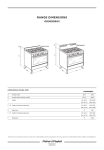
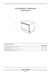
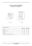
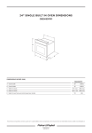
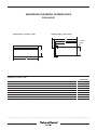
WARMING DRAWER DIMENSIONS
OD30WDX1
DIMENSIONS (FRONT VIEW)
DIMENSIONS (SIDE VIEW)
F
G
A
C
E
POWER
CORD
D
B
H
DIMENSIONS INCHES (MM)
OD30WDX1
A Overall height
10 ½”
(267)
B Overall width
29 11/16”
(754)
C Overall depth (without handle)
25 1/16”
(636)
D Height of chassis
9 ¾”
(248)
E Depth of chassis
23 ½”
(597)
F Overall depth of product including handles
28 3⁄16”
(716)
G Height from top of chassis to top of front panel
½”
(13)
H Height of bottom of chassis to bottom of front panel
¼”
(7)
Product dimensions and specifications are listed as a guide only. For complete installation instructions and specifications, refer to the product Use & Care Guide/Installation Instructions available at www.fisherpaykel.com
1.888.936.7872
WARMING DRAWER CABINET DIMENSIONS
OD30WDX1
E
A 120 volt AC GFI
outlet should be
located below the
Warming Drawer
D
A
2x4's or similar
support
B
C
DIMENSIONS INCHES (MM)
DOUBLE Wall Oven
and Warming Drawer
SINGLE Wall Oven,
Microwave & Warming Drawer
A Height of cut out
10 ± 1/16”
(254)
10 ± 1/16”
(254)
B Width of cut out
25 ¾ ± 1/16”
(654)
25 ¾ ± 1/16”
(654)
C Min. distance from face of cabinet to rear wall
> 24”
−
(610)
> 24”
−
(610)
D Center-to-center distance for 2 x 4 support boards
20”
(508)
20”
(508)
E Min. to bottom of countertop
1 ½”
(38)
1 ½”
(38)
Product dimensions and specifications are listed as a guide only. For complete installation instructions and specifications, refer to the product Use & Care Guide/Installation Instructions available at www.fisherpaykel.com
1.888.936.7872