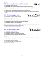
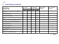
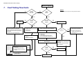
1
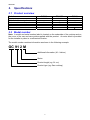
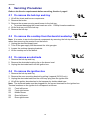
Gas Cooktops
USA, Canada
Models
GC912 and GC913 series
599328A
599328A
April 2006
Manual 599328A
Reprint: April 2006
The specifications and servicing procedures outlined in this manual are subject to change
without notice.
The latest version is indicated by the reprint date and letter and replaces any earlier
editions.
3
599328A
Contents
Models covered by this manual ......................................................................................................................5
Service assistance............................................................................................................................................5
1.
Service requirements ..............................................................................................................................6
1.1 HEALTH AND SAFETY ...............................................................................................................................6
1.2 GENERAL WARNING ..................................................................................................................................6
2.
Specifications...........................................................................................................................................7
2.1 PRODUCT OVERVIEW ................................................................................................................................7
2.2 MODEL NUMBER .......................................................................................................................................7
2.3 SERIAL NUMBER .......................................................................................................................................8
2.4 ELECTRICAL.............................................................................................................................................8
3.
Installation requirements, burner ratings and orifice sizes, gas conversion and low flame setting
adjustment.........................................................................................................................................................8
4.
Wiring diagrams .......................................................................................................................................9
4.1 GC912 COOKTOPS ..................................................................................................................................9
4.2 GC913 COOKTOP ....................................................................................................................................9
5.
Servicing Procedures ........................................................................................................................... 10
5.1 TO REMOVE THE HOB TOP AND TRAY .......................................................................................................10
5.2 TO REMOVE THE COOKTOP FROM THE BENCH/COUNTERTOP .....................................................................10
5.3 TO REMOVE AN ELECTRODE ....................................................................................................................10
5.4 TO REMOVE THE IGNITION BOX ................................................................................................................10
5.5 TO REMOVE THE MICROSWITCH ASSEMBLY ..............................................................................................11
5.6 TO REMOVE A GAS VALVE .......................................................................................................................11
5.7 TO SERVICE A GAS VALVE .......................................................................................................................11
6.
Fault finding checksheet...................................................................................................................... 12
7.
Fault finding flowcharts ....................................................................................................................... 13
4
599328A
Models covered by this manual
MODEL
GC912
GC912M
GC913
PRODUCT CODE
88441
88442
88452-A
Service assistance
Fisher & Paykel Appliances inc.
5900 Skylab Road
Huntington Beach
CA 92647
USA
Tel: 1-888-936-7872
Fax: 949-790-8913
Email: [email protected]
5
599328A
1.
Service requirements
1.1 Health and Safety
When servicing the cooktop, health and safety issues must be considered at all times.
Specific
safety issues are listed below with their appropriate icon. They are illustrated in the service
procedures to remind service people of the issues.
Electrical safety. Isolate the cooktop from the electrical supply
before servicing. Failure to do so could result in an electric shock.
Gas leak hazard. Isolate the cooktop from the gas supply if
necessary before servicing and leak test after all gas related repairs.
Sharp metal edges. Take care and use appropriate protection when
handling sharp metal edges to avoid laceration.
Gas fittings are torque sensitive, over tightening could damage them
and cause a gas leak.
Heat hazard. Ensure wiring is correctly routed away from potentially
hot metal parts.
Ensure the work area is clean and tidy at all times to avoid a hazard
while service work is being carried out. Clean the cooktop and tidy
the work area after service work is completed.
1.2 General warning
Only qualified gas and electrical service people should service this product.
6
599328A
2.
Specifications
2.1 Product overview
Model
GC912
GC912M
GC913
Supply voltage
Flame failure auto reignition
Brushed stainless steel panels
Iridium stainless steel panels
Wok burner
Indicator neons, innovalves
110/120
110/120
110/120
14000BTU/h
20000BTU/h
20000BTU/h
2.2 Model number
Note: A model and serial number label is located on the underside of the cooktop and on
the cover of the use and care guide supplied with the product. An extra label is provided
for the installer to place in a convenient location.
The model number contains information as shown in the following example:
GC 91 2 M
Additional information (M – Iridium)
Series
Product length (eg. 91 cm)
Product type (eg. Gas cooktop)
7
599328A
2.3 Serial number
The serial number consists of three letters and six digits and contains the information
shown in the following example:
B R M 123456
Sequential serial number
Manufacturing plant code
FISHERPAYKUL
manufacture
code
indicating
month
of
CUMBERLAND code indicating year of manufacture
Cumberland code
Letter C
U
M
Year 1
2
3
B
4
E
5
R
6
L
7
A
8
N
9
D
0
Fisherpaykul code
Letter F
I
S
Month 1
2
3
H
4
E
5
R
6
P
7
A
8
Y
9
K
10
U
11
L
12
Manufacturing plant code
A
Laundry – Cleveland, Australia
F
Refrigeration – Auckland, New Zealand
M
Range and Dishwasher – Dunedin, New Zealand
N
Laundry – Auckland, New Zealand
Q
Refrigeration – Cleveland, Australia
In the example above, the appliance was manufactured in the sixth month (June) of the
fourth year (2004) at the Range and Dishwasher plant in Dunedin, New Zealand.
2.4 Electrical
Mains powered ignition system – 110/120V 0.6VA
3.
Installation requirements, burner ratings and orifice
sizes, gas conversion and low flame setting
adjustment.
Refer to the installation instructions supplied with the product, or available on the Fisher &
Paykel website – http://usa.fisherpaykel.com
8
599328A
4.
Wiring diagrams
4.1 GC912 cooktops
4.2 GC913 cooktop
9
599328A
5.
Servicing Procedures
Refer to the Service requirements before servicing, Section 1 page 6
5.1 To remove the hob top and tray
1. Lift off the trivets and burner components.
2. Remove the knobs.
3. Remove the screws securing each burner to the hob tray.
To prevent damaging the screw head use a No. 1 Phillip’s head screwdriver.
4. Lift the hob tray out of the hob top.
5. Remove the hob top.
5.2 To remove the cooktop from the bench/countertop
Note: It is easier to service the internal components by removing the hob top and tray
rather than removing the product from the bench.
1. Unplug the electrical supply lead.
2. Turn off the gas supply and disconnect the inlet gas pipe.
3. Loosen the cooktop clamping brackets.
4. Lift the cooktop out of the bench.
5.3 To remove an electrode
1. Remove the hob top and tray.
2. Remove the electrode locating clip on the burner bowl.
3. Unplug the electrode lead from the ignition box.
5.4 To remove the ignition box
1.
2.
3.
4.
Remove the hob top and tray.
Remove the neon mounting bracket by pulling it upward (GC913 only).
Unplug the electrode leads and the multi-way plug from the ignition box.
Lift off the ignition box attached to the basepan by double-sided tape.
Note: The electrode leads must be plugged into the correct terminals on the ignition box.
Terminal numbers on the ignition box correspond as follows:
S1
Front left burner
S2
Front right burner
S3
Middle burner
S4
Rear left burner
S5
Rear right burner
10
599328A
5.5 To remove the microswitch assembly
1.
2.
3.
4.
5.
6.
Remove the hob top and tray.
Remove the neon mounting bracket by pulling it upward (GC913 only).
Remove the microswitch assembly wires connected to each neon (GC913 only).
Lift the switches off the gas valves.
Disconnect the active and neutral wires from the terminal block.
Disconnect the earth from the terminal block or basepan and unplug from the ignition
box.
5.6 To remove a gas valve
1.
2.
3.
4.
5.
6.
Remove the cooktop from the benchtop.
Remove the hob top and tray.
Remove the microswitch assembly.
Disconnect all the aluminium tubes from the gas valve outlets.
Remove the screws securing the manifold to the basepan.
Remove the gas valve from the manifold.
Note: Leak test all gas connections. Block each injector orifice in turn and open the valve
to leak test the gas connections beyond the valve.
Check and adjust the low flame setting.
5.7 To service a gas valve
1.
2.
3.
4.
5.
6.
7.
Remove the hob top and tray.
Remove the microswitch assembly.
Remove the screws on the top of the gas valve.
Gently lift out the valve cone and clean with solvent.
Regrease the cone with high temperature grease.
Refit and rotate the cone.
Lift out the cone, remove any excess grease and check the holes in the cone and the
valve body are not blocked.
8. Reassemble the valve assembly.
9. Open and close the valve several times.
Check the valve for leaks.
11
599328A
6.
Fault finding checksheet
Fault finding
912/913 series
Are the burner components clean and dry, not damaged and
correctly fitted
Burner not lighting
– no spark
Burner not lighting
– is sparking
On all burners?
Y
N
On all burners?
Y
N
?
?
?
Burner lights but
doesn’t stop
sparking
?
?
Is the electrode clean and dry
?
?
?
Is the electrode located correctly
?
?
?
Is the electrode damaged, is the harness shorting inside the
basepan
?
?
?
Is the electrode connected to the correct ignition box terminal
?
?
?
Is the microswitch loom correctly located and continuity ok
?
?
?
?
Is the gas pressure correct
Is the low flame setting correct
Is the cooktop set for the correct gas type, are the correct jets
fitted or is the jet blocked
Is the power supply correct (voltage and polarity), is the cooktop
properly earthed
Flame doesn’t stay
lit or is yellow or
distorted
?
?
?
?
?
?
?
?
?
?
?
Is there a draft or air flow affecting the flame
?
? - Check
12
599328A GC912/913 Gas cooktop
Burner not lighting
7.
Fault finding flowcharts
NO*
Does the
burner light
with a match?
YES
Check the low
flame setting
NO
Is the flame
behaving
normally?
YES
NOTES
Is the
electrode
sparking?
* Indicates there is not enough or too much gas flow at the burner.
NO
Are the other
electrodes
sparking?
NO
Light another burner
YES
Check the:
the burner components are assembled
correctly, are clean and dry and are not distorted.
gas jet is the correct size for the gas type and
is not blocked
cooktop doesn’t require high altitude jets.
Check the electrode:
is located correctly
is clean and dry
is not damaged.
Replace the:
electrode
burner cap and spreader.
Ensure the burner components are assembled
correctly, are clean and dry and not damaged.
Check the electrode:
is clean and dry
is not damaged
is not shorting inside the basepan area
lead is connected tightly at the ignition box.
Swap the electrode lead at the ignition box with one
that is working ok.
Check the:
gas pressure
gas valve for grease blockage
gas pipes/connections for gas leak
or blockage.
These repairs require gas
qualifications.
Does the
electrode
spark now?
Does it
function ok?
NO
Check the:
power supply up to the ignition
box
connections at the ignition box
continuity of the common wire in
the microswitch loom.
YES
Check the:
microswitch loom connections at the
ignition box
continuity, mounting and operation
of the microswitch.
NO
Replace the electrode
YES
Replace the ignition box
13
599328A GC912/913 Gas cooktop
Sparking continuously
NO
Refer to Burner not lighting flowchart
Does the burner
light and
continue
sparking?
YES
Is a burner in
use?
NO
Check for:
shorted ignition switches in the loom
incorrect polarity at the power outlet.
YES *
Is the flame
behaving
normally?
Check the:
burner components are assembled correctly, are clean and dry
and not distorted
gas jet is the correct size for the gas type and is not blocked
low flame setting is correctly set
cooktop doesn’t require high altitude jets.
NO
YES
Check the:
electrode/burners are clean and dry
low flame setting is correctly set
Check the gas pressure
**electrode leads are firmly connected to their correct location at the
ignition box and are not damaged
earth to the cooktop and earthing connections in the cooktop are ok.
Replace the ignition box
NOTES
* Indicates the flame isn’t being sensed.
** The correct electrode positions at the ignition box Terminal
S1
S2
S3
S4
S5
Burner
Front left
Front right
Middle
Rear left
Rear right
14
These repairs
require gas
qualifications.