1
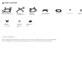
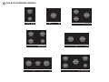
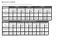
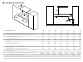
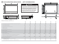
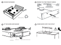
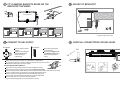
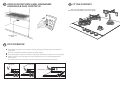
INSTALLATION INSTRUCTIONS
Gas-on-glass cooktop
CG302D, CG451D, CG603D, CG604D,
CG752D, CG903D & CG905D
models
NZ AU
590149D
02.13
1 SAFETY AND WARNINGS
WARNING!
Electrical shock hazard
Before carrying out any work on the electrical section of the appliance, it must
be disconnected from the mains electricity supply.
Connection to a good earth wiring system is absolutely essential and
mandatory.
Alterations to the domestic wiring system must only be made by a qualified
electrician.
Failure to follow this advice may result in electrical shock or death.
WARNING!
Cut hazard
Take care - some panel edges are sharp.
Failure to use caution could result in injury or cuts.
IMPORTANT SAFETY INSTRUCTIONS!
Particular attention shall be given to the relevant requirements regarding ventilation.
Read these instructions carefully before installing this product.
Please make this information available to the person installing the appliance as it could reduce your
installation costs.
This appliance is to be installed and serviced only by an authorised person.
Installation must comply with your local building and local gas authority codes and electricity
regulations.
Incorrect installation, for which the manufacturer accepts no responsibility, may cause personal
injury or damage and could invalidate any warranty or liability claims.
These appliances are registered in: (New Zealand) at www.energysafety.govt.nz and (Australia) with
SAI Global at www.saiglobal.com.
This gas appliance is suitable for connection only to the gas type for which it was set at the factory,
as declared on the appliance data label. It is not convertible for use on any other gas type. If in
doubt, refer to the local gas network operator or gas supplier to confirm gas type at installation site.
Do not modify this appliance.
2
Do not use or store flammable materials on or near this appliance.
Do not spray aerosols in the vicinity of this appliance while it is in operation.
Packing elements (eg plastic bags, polystyrene foam, staples, packing straps etc) and tools should not
be left around during and after installation, especially if they are within easy reach of children, as these
may cause serious injuries.
You must remove the transit screws before installing the cooktop. See step 8 of installation
instructions.
Before you install the appliance, please make sure that
the local distribution conditions (nature of gas and pressure) and the adjustment of the appliance
are compatible. For adjustment conditions for this appliance see ‘Gas rate summary’.
a suitable disconnection switch is incorporated in the permanent wiring, mounted and positioned to
comply with the local wiring rules and regulations. A means of disconnection with at least a 3 mm
air gap contact separation in all poles must be incorporated into the fixed wiring in accordance with
the wiring rules, unless the local wiring rules allow for alternative means.
the appliance is connected to a 220V - 240V 50Hz (10 A) power supply only and earthed via the
power supply cable.
there is a power outlet within reach of the power supply cable (900 mm from the centre rear of the
product). This must be accessible after installation. The power supply cable should not touch any
metal parts.
if the power supply cable is damaged, it is replaced only by the special cable: Part no. 534050 - Flex
Terminal Block Assy NZ/AU, obtainable from authorised Fisher & Paykel Service Agents.
the supply connection point (gas shut-off valve) is accessible after installation.
the benchtop is made of a heat resistant material.
the installation complies with all the requirements of Australian and New Zealand Gas Installation
Standards (AS/NZS 5601.1.2010), including that the product has to be installed so that the surface
temperature of any nearby combustible surface will not exceed 65 OC above ambient. See step 5
‘Clearance Dimensions’.
When you install the appliance
We do not recommend you flush mount or seal this appliance into the bench with silicone or glue.
Doing so will make future servicing difficult. Fisher & Paykel will not be liable for any costs associated
with removing or replacing a sealed-in appliance, nor for repairing any damage that may be incurred
by doing this.
If installed with an approved flexible hose, the hose should not come in contact with the bottom of
the appliance or any sharp edges. Flexible hose assemblies should be AS/NZS 1869 Class B or Class D
certified.
Seal exposed bare edges of the cutout with an oil-based paint or moisture-proof polyurethane to
prevent possible moisture creeping between the cooktop trim and the benchtop.
Take extreme care not to chip, crack, or break the top glass surfaces during installation. A heavy
metal tool or part accidentally dropped on the glass could damage it.
If, after following the instructions given, correct performance cannot be achieved, please contact
your nearest Fisher & Paykel Authorised Service Centre, Customer Care, or contact us through our
website listed at the end of this document.
3
2 PARTS SUPPLIED
Dual Wok Pan support
(Models with a Dual Wok only)
Clamping
brackets (4)
and screws (4)
Pan support
(not supplied with
Dual Wok only models)
LPG test point
adaptor (1)
(LPG models
only)
Mini wok Pan
support (1)
(CG604D only)
Small pan support (1)
(some models only)
Wok stand (1)
NG regulator (1)
(NG models
only)
Installing multiple products
Note: if installing multiple products adjacent to each other within the same cutout, a separate joining strip kit is required for installation.
The kit is available from the nearest Fisher & Paykel Authorised Service Centre or our website listed at the end of this document.
Fibre washer (1)
Elbow 1/2“ BSP
external thread (1)
3 GAS RATE SUMMARY-MODELS
4
SEMI-RAPID
SEMI-RAPID
DUAL WOK
DUAL WOK
SEMI-RAPID
AUX
CG302D
SEMI-RAPID
CG451D
CG603D
SEMI-RAPID
DUAL WOK
MINI WOK
DUAL WOK
AUX
CG604D
CG752D
SEMI-RAPID
SEMI-RAPID
DUAL WOK
DUAL WOK
SEMI-RAPID
DUAL WOK
RAPID
CG903D
CG905D
AUX
3 GAS RATE SUMMARY
5
All appliances are factory set for Natural gas or LPG and are not convertible. Check the appliance data label.
CG302D
BURNER
AUX
CG451D
SEMI-RAPID
CG603D
DUAL WOK
SEMI-RAPID
DUAL WOK
Jet size
(mm)
Nominal
rating
(MJ/h)
Jet size
(mm)
Nominal
rating
(MJ/h)
Jet size
(mm)
Nominal
rating
(MJ/h)
Jet size
(mm)
Nominal
rating
(MJ/h)
Jet size
(mm)
Nominal
rating
(MJ/h)
NG (1.00 kPa)*
1.00
5.0
1.35
8.8
1.43
1.43
0.70
21.0
1.30
8.4
1.26
1.26
0.70
16.6
LPG (2.75
kPa)*
0.64
5.0
0.80
8.1
0.80
0.80
0.50
19.5
0.76
7.5
0.73
0.73
0.50
16.8
GAS TYPE
CG604D, CG752, CG903 & CG905
BURNER
GAS TYPE
AUX
Jet size
(mm)
SEMI-RAPID
Nominal
rating
(MJ/h)
Jet size
(mm)
Nominal
rating
(MJ/h)
RAPID
Jet size
(mm)
Nominal
rating
(MJ/h)
MINI WOK
Jet size
(mm)
DUAL WOK
Nominal
rating
(MJ/h)
Jet size
(mm)
Nominal
rating
(MJ/h)
18
18
NG (1.00 kPa)*
0.85
3.6
1.30
8.3
1.55
11.5
1.55
11.7
1.30
1.30
0.70
LPG (2.75
kPa)*
0.55
3.6
0.76
7.5
0.94
11.5
0.94
11.7
0.76
0.76
0.50
*Nominal pressure with at least one large burner on High.
4 PRODUCT & CABINETRY DIMENSIONS
6
G
B
C
H
I
TOP
TOP
Note: Gas inlet connection is
located in the rear right corner.
A
K
E
D
J
F
REAR
FRONT
SIDE
Product and cabinetry dimensions (mm)
CG302D
CG451D
CG603D
CG604D
CG752D
CG903D
CG905D
A
B
C
D
E
F
G
H
I
J
K
64
64
64
64
64
64
64
overall width of product
300
450
600
600
750
900
900
overall depth of product
530
530
530
530
450
450
530
59
59
59
59
59
59
59
width of chassis
256
406
555
555
706
856
856
depth of chassis
486
486
486
486
410
410
486
overall width of cutout
265
415
560
560
715
865
865
overall depth of cutout
490
490
490
490
410
410
490
corner radius of cutout
overall height of product (excluding burners, dials and pan supports)
height of chassis (below top of bench)
max. 10
max. 10
max. 10
max. 10
max. 10
max. 10
max. 10
distance from top of bench to centre of gas inlet on product
30
30
30
30
30
30
30
distance from edge of chassis to gas inlet on product
21
21
21
21
21
21
21
5 CLEARANCE DIMENSIONS
7
I
E
D
C
F
A
G
B
H
ISO
FRONT
CG302D
CG451D
CG603D
CG604D
CG752D
CG903D
CG905D
minimum clearance from left edge of cutout to nearest combustible surface
120
60
115
130
115
115
130
minimum clearance from right edge of cutout to nearest combustible surface
minimum clearance from rear edge of cutout to:
nearest combustible surface
nearest non-combustible surface
minimum height of non-combustible material when used on adjacent walls
minimum clearance from glass surface to:
rangehood
any other overhead exhaust fan
downward facing combustible surface
downwards-facing tiled or fire resistant surface
minimum clearance below top of benchtop to:
combustible surface
Fisher & Paykel oven or nearest non-combustible surface
minimum distance from right edge of cooktop to gas connection point on wall
(if using a flexible hose)
120
60
115
115
115
115
115
160
45
150
85
45
150
160
45
150
160
45
150
125
45
150
125
45
150
160
45
150
650
800
650
500
650
800
650
500
650
800
650
500
650
800
650
500
650
800
650
500
650
800
650
500
650
800
650
500
70
65
70
65
70
65
70
65
70
65
70
65
70
65
250
250
250
250
250
250
250
min. 800 max. 850
600
min. 800 max. 850
600
min. 800 max. 850
600
min. 800 max. 850
600
min. 800 max. 850
600
min. 800 max. 850
600
min. 800 max. 850
600
Clearance dimensions (mm)
A
B
C
D
E
F
G
H
distance from floor to gas connection point on wall (if using a flexible hose)
I
maximum overall depth of overhead cabinetry
Note: Ensure there is an earthed power outlet within 900 mm of the centre rear of the product. The gas connector on the wall should be 800-850 mm (H) above the floor and to a distance of at least 250 mm (G) outside the width
of the product, on the right-hand side. It should be accessible with the product installed.
6 FLUSH MOUNTING INSTALLATION
(NOT RECOMMENDED)
B
8
G
G
WARNING!
We do not recommend flush mounting and sealing as
servicing requires the cooktop to be removed from the
benchtop. The owner carries all risk for flush mounting
the cooktop. The owner must ensure the cooktop has
been cut out from the benchtop before servicing can
be carried out. Fisher & Paykel will not be liable for any
costs associated with removing or replacing a flushmounted and/or sealed-in product, nor for repairing
any damage that may be incurred by doing this.
C
HH
I
TOP
Note: Gas inlet connection is
located in the rear right corner.
L
TOP
A
K
E
D
F
REAR
M
J
FRONT
N
SIDE
Product and cabinetry dimensions (mm)
CG905D
CG903D
CG752D
CG604D
CG603D
N
overall height of product (excluding burners, dials and pan supports)
CG451D
CG302D
A
B
C
D
E
F
G
I
G
H
I
H
I
J
K
L
M
64
64
64
64
64
64
64
overall width of product
300
450
600
600
750
900
900
overall depth of product
530
530
530
530
450
450
530
64
64
64
64
64
64
64
width of chassis
256
406
555
555
706
856
856
depth of chassis
486
486
486
486
406
406
486
overall width of routered recess
305
455
605
605
755
905
905
width of cutout
265
415
560
560
715
865
865
overall depth of routered recess
535
535
535
535
455
455
535
depth of cutout
490
490
490
490
410
410
490
height of chassis (below top of bench)
corner radius of cutout
max. 10
max. 10
max. 10
max. 10
max. 10
max. 10
max. 10
distance from top of bench to centre of gas inlet on product
35
35
35
35
35
35
35
distance from edge of chassis to gas inlet on product
21
21
21
21
21
21
21
max. 2
max. 2
max. 2
max. 2
max. 2
max. 2
max. 2
5
5
5
5
5
5
5
75
70
75
70
75
70
75
70
75
70
75
70
75
70
corner radius of routered recess
height of routered recess
minimum clearance below top of benchtop to:
combustible surface
Fisher & Paykel oven or nearest non-combustible surface
6 FLUSH MOUNTING INSTALLATION
6a ROUTER THE BENCHTOP TO THE
SPECIFIED DEPTH
(NOT RECOMMENDED)
6b FIT THE CLAMPING BRACKETS
9
6c MASK OFF THE AREA TO BE
SILICONED
x4
1
view from below
2
3
Choose most
appropriate slot
for benchtop
5 mm
16 - 50mm
6d APPLY SILICONE
6e WIPE OFF EXCESS SILICONE
6f IF REMOVING PRODUCT, CUT
AROUND THE SILICONE
TO REMOVE PRODUCT
2
min. 150 OC rated
1
Ensure silicone does not leak underneath glass.
7 DISCARD PACKAGING
8 REMOVE THE TWO TRANSIT SCREWS
Recycle responsibly
9 FIT THE ELBOW AND WASHER
Fibre washer
Floating nut
Repeat on the other side
10 LOWER GENTLY INTO THE CUTOUT
Elbow (1/2” BSP external thread)
10
11 FIT CLAMPING BRACKETS BASED ON THE
11
12 SECURE TO BENCHTOP
BENCHTOP THICKNESS
x4
view from below
x4
16-20mm
20-30mm
30-40mm
40mm+
13 CONNECT TO GAS SUPPLY
NG Models
Arrow
Make sure to fit the supplied
regulator.
Adjust to obtain a test point
pressure of 1 kPa with all
burners operating at
highest setting.
LPG Models
Repeat on all the other sides
14 CHECK ALL CONNECTIONS FOR GAS LEAKS
Make sure to fit the supplied
test point adaptor.
Make sure the supply pressure
is regulated to 2.75 kPa, with all
burners operating at highest
setting.
ALL Models
Make sure the connection point will be accessible with the cooktop installed.
To enable the gas supply to be readily shut off by the customer, make sure the connection
is fitted with an isolating valve close to the cooktop.
If connecting the gas with a flexible hose:
Ensure the hose is long enough to allow for removal of cooktop for servicing.
Make sure the connector is located as shown in step 5 CLEARANCE DIMENSIONS.
The hose assembly must be AS/NZS 1869 Class B or D certified, with an Rp ½”(ISO 7‐1) female thread connection.
The hose assembly must be no longer than 1.2 m in length with minimum internal
diameter of 10 mm and comply with relevant AS 5601/NZS 5261 requirements.
The hose must not be kinked, subjected to abrasion or permanently deformed.
The hose must not be near or in contact with any hot surfaces
(e.g. base of metal hotlplate, flue, or chassis of underbench oven etc.)
GAS
GAS
ON
ON
15 AFFIX DUPLICATE DATA LABEL SOMEWHERE
ACCESSIBLE & PLUG COOKTOP IN
16 FIT PAN SUPPORTS
Ensure the pan supports are located securely
and in the correct orientation (refer to User guide)
Duplicate data
label
17 TEST OPERATION
To check that the ignition system operates correctly, light each burner by itself, then all burners in
combination.
Check for a well‐defined blue flame without any yellow tipping.
If any abnormality is evident, check that the components of the burner assembly are located properly
If proper operation cannot be obtained, contact Customer Care or your nearest F&P Authorised
Service Centre.
The cooktop must not be used by the customer until proper operation has been achieved.
lifting off
yellow tip
good flame
12
18 FINAL CHECKLIST
13
TO BE COMPLETED BY THE INSTALLER
Installer’s name:
Have you installed the clamping brackets?
Installer’s signature:
Have you verified that the type of model (factory-set for NG or LPG)
matches the type of gas at the site of installation?
Installation company:
Date of installation:
Have you used the fibre washer supplied?
Have you leak-tested all connections?
LEAVE THESE INSTRUCTIONS WITH THE CUSTOMER
Is the appliance set to the correct working pressure?
Have you affixed the supplied duplicate data plate label on an adjacent
surface accessible to the customer?
Is the cooktop earthed?
Important!
SAVE THESE INSTRUCTIONS
The models shown in this document may not be available in all markets and are subject to change
at any time. For current details about model and specification availability in your country, please
visit our local website listed at the end of this document or contact your local Fisher & Paykel
dealer.
Have you checked that the power supply cable is NOT touching the cooktop?
OPERATION:
Do all burners ignite both individually and in combination?
Are the flames consistent and appropriately sized?
Have you demonstrated the basic operation to the customer?
www.fisherpaykel.com