1
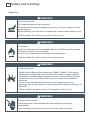
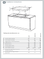
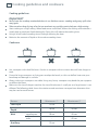
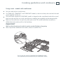
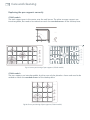
Installation instructions
and User guide
Gas cooktops
CG604 & CG905 models
NZ AU
Contents
Safety and warnings
Installation instructions
Introduction
Using your cooktop
Cooking guidelines and cookware
Care and cleaning
Troubleshooting
Warranty and service
Important!
SAVE THESE INSTRUCTIONS
The models shown in this document may not be available in all markets and are
subject to change at any time. For current details about model and specification
availability in your country, please visit our local website listed on the back cover
or contact your local Fisher & Paykel dealer.
1
2
6
16
17
20
22
27
29
2
Safety and warnings
Installation
WARNING!
Electrical Shock Hazard
Before carrying out any work on the electrical section of the appliance, it must
be disconnected from the mains electricity supply.
Connection to a good earth wiring system is absolutely essential and
mandatory.
Alterations to the domestic wiring system must only be made by a qualified
electrician.
Failure to follow this advice may result in electrical shock or death.
WARNING!
Cut Hazard
Beware of sharp edges when handling stainless steel appliances.
Failure to use caution could result in injury or cuts.
Safety and warnings
3
Important safety instructions!
Installation
Read these instructions carefully before installing or using this product.
Please make this information available to the person responsible for installing the product as it
could reduce your installation costs.
This appliance shall only be installed and serviced by an authorised person.
Incorrect installation, for which the manufacturer accepts no responsibility, may cause personal
injury or damage and could invalidate any warranty or liability claims.
This appliance must be installed in accordance with these installation instructions and in
compliance with local gas fitting regulations, municipal building codes, water supply regulations,
electrical regulations, AS5601/AG601 and NZS5261 – Gas installations and any other relevant
statutory regulations.
Do not modify this appliance.
Models without flame failure protection MUST NOT be installed in marine craft, caravans or
mobile homes.
When this appliance is installed, it shall not be used as a space heater.
No combustible materials or products should be placed on this appliance at any time.
Do not spray aerosols in the vicinity of this appliance while it is in operation.
This appliance should not be sealed into the bench with silicone or glue. Doing so will make
future servicing difficult. Fisher & Paykel will not be liable for costs associated with releasing such
a product, nor for repairing damage that may be incurred in doing this.
Packing elements (eg plastic bags, polystyrene foam, staples, packing straps etc) and tools
should not be left around during and after installation, especially if they are within easy reach of
children, as these may cause serious injuries.
4
Safety and warnings
Operation
WARNING!
Hot Surface Hazard
This appliance becomes hot during use.
Do not touch the cooktop components, burners, trivets, pan supports or the
base when hot.
Before cleaning, turn the burners off and make sure the whole cooktop is cool.
Failure to follow this advice may result in serious injury.
WARNING!
Fire Hazard
Never leave the appliance unattended when in use. Boilover causes smoking
and greasy spillovers that may ignite.
Never use your appliance for warming or heating the room.
Failure to follow this advice may result in serious injury.
WARNING!
Explosion Hazard
Models with no flame failure protection (CG604L, CG604C): If the flame is
accidentally extinguished, turn the control dials and gas supply valve off
immediately and thoroughly ventilate the room. Do not attempt to relight
any burner until you are certain that all gas that may have escaped has
dispersed.
Do not use or store flammable materials such as gasoline near this
appliance. Do not spray aerosols in the vicinity of this appliance while it is in
operation.
Failure to follow this advice may result in death or serious injury.
WARNING!
Electrical Shock Hazard
Switch the power to the cooktop off at the wall before cleaning or
maintenance.
Failure to follow this advice may result in death or electrical shock.
Safety and warnings
5
Important safety instructions!
Operation
Keep children away from the cooktop when it is in use.
Household appliances are not intended to be played with by children.
Children, or persons with a disability which limits their ability to use the appliance, should
have a responsible person to instruct them in its use. The instructor should be satisfied that
they can use the appliance without danger to themselves or their surroundings.
If the electrical supply cord is damaged, it must only be replaced by an authorised person.
Ensure that the electrical connection plug is accessible after installation.
This appliance should be connected to a circuit that incorporates an isolating switch
providing full disconnection from the electricity supply.
Do not use an asbestos mat or decorative covers between the flame and the saucepan as
this may cause serious damage to your cooktop.
Do not place aluminium foil or plastic dishes on the cooktop burners.
Do not let large saucepans or frying pans overlap the bench as this can deflect heat onto
your benchtop and damage the surface.
Do not let large saucepans, frying pans or woks push any other pans aside. This could make
them unstable or deflect heat onto your benchtop and damage the surface.
Do not use a steam cleaner for cleaning this cooktop.
Saucepan handles may be hot to touch. Ensure saucepan handles do not overhang other
gas burners that are on. Keep handles out of reach of children.
Do not stand or place heavy objects on this appliance.
After use, ensure that the control dials are in the ‘OFF’ position.
This appliance shall not be used as a space heater, especially if installed in marine craft or
caravans.
The use of a gas cooking appliance results in the production of heat and moisture in the
room in which it is installed. Ensure the kitchen is well ventilated. Keep natural ventilation
holes open or install a mechanical ventilation device (mechanical extractor hood).
Prolonged intensive use of the appliance may call for additional ventilation, for example
opening of a window, or more effective ventilation, for example increasing the level of
mechanical ventilation where present.
After having unpacked the appliance, check to ensure that it is not damaged.
In case of doubt, do not use it and consult your supplier or a professionally qualified technician.
Packing elements (eg plastic bags, polystyrene foam, nails, packing straps, etc.) should not be
left around within easy reach of children, as these may cause serious injuries.
Some appliances are supplied with a protective film on steel and aluminium parts. This film
must be removed before using the appliance.
6
Installation instructions
A
B
E
D
C
H
J
G
I
F
J
CG905DWAC
I
CG905DWFC
A
B
C
D
E
F
G
H
CG604
Cooktop and cutout dimensions (mm)
overall width of cooktop
578
914
914
overall depth of cooktop
511
533
546
height of chassis below top of bench
50
50
76
width of chassis
554
840
855
depth of chassis
480
480
470
overall width of cutout
560
870
870
overall depth of cutout
corner radius of cutout
distance from right edge of cutout to
manifold centre line
distance from rear edge of cutout
to gas inlet
490
494
494
max. 10
max. 10
max. 10
30
30
30
40
47
35
Installation instructions
7
C
E
D
A
F
B
G
CG604
CG905DWAC
(mm)
CG905DWFC
Clearances
H
minimum clearance from left edge of cutout to:
140
140
100
nearest combustible surface
minimum clearance from right edge of cutout to:
B
140
140
100
nearest combustible surface
minimum clearance from rear edge of cutout to:
nearest combustible surface
C
110
110
115
nearest non-combustible surface
20
30
35
minimum height of non-combustible material when used on
D* adjacent walls
150
150
150
minimum clearance from pan supports to:
rangehood
650
650
650
any other overhead exhaust fan
E
800
800
800
downward-facing combustible surface (overhead cabinetry)
650
650
650
downward-facing tiled or fire-resistant surface
500
500
500
minimum clearance below top of benchtop to:
nearest combustible surface
F
60
60
81
F&P oven or nearest non-combustible surface
60
60
81
Ensure there is an earthed power outlet within 900 mm of the rear right-hand corner of the cookG top. The outlet should be accessible with the cooktop installed.
If connecting the cooktop to the gas supply with a flexible hose, the connector on the wall should
H be between 800-850 mm above the floor and to a distance of at least 250 mm outside the width
of the cooktop. The connector should be accessible with the cooktop installed.
A
* See section ‘Standards requirements’ following.
8
Installation instructions
Before you start
Before starting to install the cooktop, make sure that:
the cooktop has not been damaged during transport. In case of doubt after unpacking and
checking it, contact the retailer
the local distribution conditions (nature of gas and pressure) and the adjustment of the cooktop
(as detailed on the appliance data label and in the ‘Gas rate and injector size table’ further
below) are compatible
the cooktop will be connected to a 220-240 V 50 Hz power supply and earthed via the power
supply cable
there is an earthed power outlet within the reach of the cooktop’s power supply cable (within
900 mm from the rear right of the cooktop, see dimension G in ‘Clearances’)
the power outlet will be accessible after installation
the power supply cable will not touch any hot metal parts
a suitable isolating switch providing full disconnection from the mains power supply is
incorporated in the permanent wiring, mounted and positioned to comply with local wiring
rules and regulations. The isolating switch must be of an approved type and provide a 3 mm air
gap contact separation in all poles (or in all active [phase] conductors if the local wiring rules
allow for this variation of the requirements)
the isolating switch will be accessible after installation
the benchtop is made of a heat-resistant material
exposed bare edges of the cutout are sealed with an oil-based paint or moistureproof
polyurethane to prevent possible damage from moisture creeping between the cooktop trim
and the benchtop.
Standards requirements
Temperature of nearby surfaces. Australian and New Zealand Gas Installation Standards
(AS5601, NZS5261) require a cooktop to be installed so that the surface temperature of any
nearby combustible surface will not exceed 65oC above ambient. This is typically achieved by:
having the cooktop spaced away from the wall (see dimensions A, B, and C in ‘Clearances’)
OR
protecting the wall to a height of at least 150 mm along its length (see dimension D in
‘Clearances’) with non-combustible surface materials such as:
- 5 mm-thick ceramic tiles—these alone are adequate
- tempered glass or sheetmetal (minimum thickness 0.4 mm)—acceptable when used in
front of a fire resistant material
- F&P splashback (not available in Australia) when used with a 10 mm clearance from the
rear edge of the cooktop to the front of the splashback (SB90 and SB1216 splashback
models only).
Note: these cooktops have been tested by an independent testing lab and meet standards
requirements when installed to the dimensions in these instructions.
Installation instructions
9
Fastening the cooktop to the bench
This cooktop is suppled with fastening brackets (and screws) that will cope with a
bench thickness of 20-50 mm. For benches thicker than 50 mm, recess the underside
to a thickness of 20-50 mm.
50 mm
20 mm
recessed to
50 mm
Fig.1 Fastening the cooktop to the bench
Connecting the cooktop to the gas supply
Important!
This cooktop is supplied factory-set for Natural Gas, but is suitable for installation with either
Natural Gas or LPG, provided the injectors appropriate for the gas type are installed. Refer to
the ‘Gas rate and injector size table’ for nominal ratings and appropriate injector sizes, and to
section ‘Converting to a different gas type’.
The gas connection must be carried out by a suitably qualified person according to the relevant
standards.
For Natural Gas, connect the gas supply to the gas pressure regulator supplied with the cooktop.
Adjust the regulator to obtain a test point pressure of 1 kPa (4”W.C.) with the three largest
burners operating at the highest setting.
For LPG, connect the the gas supply to the test point adaptor supplied with the cooktop. Ensure
that the supply pressure is regulated to 2.75 kPa (11” W.C.) See section ‘Converting to a different
gas type’.
Make sure the connection point will be accessible with the cooktop installed.
To enable the gas supply to be readily shut off, make sure the connection is fitted with an
isolating valve close to the cooktop.
Attach the duplicate appliance data label on a surface adjacent to the cooktop, so that it will be
easily read with the cooktop installed.
For instructions on converting the cooktop for use with a different gas type, see section
‘Converting to a different gas type’.
10
Installation instructions
Special requirements for CG604 and CG905DWFC models
Gas connection to these cooktops MUST use the elbow supplied. The regulator will not seal if
installed without it.
Ensure the fibre washer (supplied) is located between the elbow (supplied) and cooktop gas
inlet (Fig.2). Failure to use this washer will cause the connection to leak. Tighten the floating
nut to firm finger tight, plus an additional ¼ turn (90o).
Gas connection with a flexible hose
If the gas is connected with a flexible hose, the connector on the wall should be between 800850 mm above the floor and to a distance of at least 250 mm outside the width of the cooktop.
The connector should be accessible with the cooktop installed.
Flexible hose assemblies should be AS/NZS 1869 Class B or Class D certified. The thread
connection shall be Rp ½” (ISO 7-1) female (for CG604 and CG905DWFC models) or male (for
CG905DWAC models). See Figs. 2 and 3.
The hose assembly must be as short as practicable and comply with relevant AS 5601/NZS 5261
requirements.
The hose must not be kinked, subjected to abrasion or permanently deformed.
The hose must not be near or in contact with any hot surfaces (eg base of metal hotplate, flue or
chassis of underbench oven etc).
Fibre washer
Elbow (1/2” BSP external thread)
Fig.2 Gas connection to the cooktop (CG604
and CG905DWFC models)
Gas inlet (1/2” BSP internal thread)
Fig.3 Gas connection to the cooktop
(CG905DWAC models)
Installation instructions
11
Leak-testing and flame-testing the cooktop
Important!
The operation of the cooktop, including the ignition system, must be tested before installation is complete.
If, after following the instructions below, satisfactory performance cannot be obtained, contact the local
gas authority or your local Authorised Repairer for advice and assistance.
1
2
3
Checking the connections for leaks
After installation and making all connections, check thoroughly for possible leaks and make sure
all connections are gas-tight.
Turn all control dials to O (OFF).
Open the valve on the gas supply.
Check each connection one at a time by brushing a soap and water solution or a suitable leak
detection fluid over it.
Important!
Do not use any naked flames to check for leaks.
The presence of bubbles indicates a leak. Tighten or replace connections as appropriate, then
leak-test all connections again. For CG604 and CG905DWFC models, ensure the fibre washer
(supplied) is located between the elbow and the cooktop’s gas inlet.
1
2
Checking the burner flames
Light each burner.
Check for a well-defined blue flame without any yellow tipping. See Fig.4.
If any abnormality is evident, check that:
- the burner cap is located properly
- the injector nipple is correctly aligned
- the correct size injectors are installed.
Incorrect: flame
‘lifting off’ the burner
Incorrect:
yellow tipping
Good flame: well-defined blue flame
without yellow tipping
Fig.4 Incorrect and good flame patterns
12
Installation instructions
Converting to a different gas type
Important!
1
Gas conversion may only be carried out by a suitably qualified person.
To convert from one gas type to another, you need to replace the injectors and adjust the
minimum burner setting.
To replace the injectors, you will need a 7 mm box spanner (and a 10 mm ring spanner for
CG905DWAC models). These are not supplied.
Switch the power supply to the cooktop off at at the wall.
Important!
2
3
4
5
Disconnect cooktop from the power supply before continuing.
Make sure each control dial is turned to O (OFF).
Remove all the pan supports and burner heads.
Pull off the control dials.
Using a 7 mm box spanner, remove the injectors and replace them with the correct ones
(size numbers are stamped on the inside, eg 70=0.70 mm). Hold on to the card housing the
replacement injectors for later use.
CG905DWAC only
6
Remove all the screws holding the burners in place.
7
Carefully lift the hob tray off the cooktop.
Important!
11
12
13
14
15
16
Beware of sharp edges.
8
Replace the wok burner injector with the correct one using a 10 mm ring spanner.
Reset the venturi. Loosen the venturi screw, move the venturi towards the injector approx.
9
2 mm.
10
Refit the hob tray on the cooktop, repeating steps 6 and 7 in reverse.
Check insulation resistance and earth continuity.
Switch the power supply to the cooktop back on at the wall.
Refit the control dials.
Adjust the minimum burner setting. See section ‘Adjusting the minimum burner setting’
following.
Check that all burners have a good flame (Fig.4).
To indicate the gas type change, peel the adhesive label off the replacement injector card and
stick it into the framed ‘gas type’ area on the appliance data label (on the underside of the
cooktop). A second conversion label should also be affixed to the duplicate appliance data label.
Installation instructions
13
Adjusting the minimum burner setting
This has been adjusted at the factory for Natural Gas but may need adjusting for local
conditions.
When converting to LPG, the minimum setting MUST be re-adjusted for each burner.
To adjust the minimum setting, you will need a Ø 2.5 x 45 mm screwdriver.
1
2
3
4
5
Light the burner and set the control dial to its minimum.
Remove the dial.
Slowly turn the adjustment screw inside the valve shaft until a minimum regular flame is
achieved. Note:
The flame will diminish when the screw is turned clockwise, and increase when turned
anti-clockwise.
The brass wok burner in the centre of CG905DWAC models may require progressive
venturi adjustment (Fig. 6) until a good flame (Fig.4) is achieved:
- If the flame is ‘lifting off’ the burner, move the venturi closer to the injector.
- If there is yellow tipping, move the venturi away from the injector.
Refit the dial.
Check the minimum burner setting: quickly turn the dial from maximum to minimum. The flame
must not go out. If it does, repeat the steps above.
Repeat the steps above for each burner.
Venturi
NG venturi position
LPG venturi position
Fig.5 Adjusting the minimum burner setting
Fig.6 Progressive venturi adjustment for the
brass wok burner on CG905DWAC models
14
Installation instructions
Gas rate and injector size table
Test point pressure (kPa)
Burners
NATURAL GAS
LPG
1.0
2.75
Injector
Nominal
orifice size gas rate
(mm)
(MJ/h@1kPa)
Injector
orifice size
(mm)
Nominal
gas rate
(MJ/[email protected])
CG604LC, CG604CWC, CG604DWFC, CG905DWFC
Auxiliary (right front)
0.85
3.6
0.55
4.0
Semi-rapid (left & right rear)
1.30
8.5
0.80
8.5
Wok (left front in CG604CWC,
CG604DWFC, left front &
centre in CG905DWFC)
1.75
15.0
1.00
13.5
Rapid (left front in CG604LC)
1.55
12.0
0.95
12.0
Auxiliary (right front)
0.85
3.6
0.45
2.7
Semi-rapid (left rear)
1.22
7.2
0.70
6.2
Wok (centre)
1.90
16.3
1.10
15.3
Rapid (left front & right rear)
1.45
10.5
0.85
9.3
CG905DWAC
Installation instructions
15
Final checklist
TO BE COMPLETED BY THE INSTALLER
Have you securely fastened the cooktop to the bench with the supplied brackets?
All models except CG905DWAC: Have you used the supplied elbow and fibre washer to connect
the gas to the inlet on the cooktop?
Have you leak-tested all connections?
Are the injector sizes correct for the gas type?
Is the shut-off valve on the gas supply accessible to the customer?
Is the power supply isolating switch accessible to the customer?
Is the cooktop power supply cable plugged into an earthed outlet?
Check the entire length of the power supply cable: it should not touch any hot metal parts.
Have you removed all protective film from the stainless steel surfaces?
Have you disposed of all packaging elements?
OPERATION:
Do all burners light individually and in combination?
Do the burners remain lit when turned quickly from maximum to minimum?
Are the flames consistent, free from any yellow tipping and appropriately sized?
Have you demonstrated the basic operation to the customer?
Installer’s name:
Installer’s signature:
Installation company:
Date of installation:
LEAVE THESE INSTRUCTIONS WITH THE CUSTOMER
16
Introduction
About your new cooktop
Thank you for buying a Fisher & Paykel gas cooktop. Once it is installed and ready to use, you
will want to know everything about it to make sure you get excellent results right from the start.
We recommend you read the whole guide before using your new cooktop, for both safety and
cooking success.
For more information, visit our local website listed on the back cover.
Before using your new cooktop
Read this user guide, taking special note of the ‘Safety and warnings’ section.
Ensure the power supply to the cooktop is turned on.
5
5
1
1
1
2
4
3
Fig.7 Cooktop layout - CG604LC
(no flame failure protection)
1
4
Fig.8 Cooktop layout - CG604CWC (no flame
failure protection) and CG604DWFC (with
flame failure protection)
5
5
1
1
1
2
3
3
3
2
4
Fig.9 Cooktop layout - CG905DWFC
(with flame failure protection)
4
Fig.10 Cooktop layout - CG905DWAC
(with auto-reignition)
1
2
3
4
5
Semi-rapid burner
Rapid burner
Wok burner
Auxiliary burner
Control dials
Using your cooktop
17
Control dials
The dials control the flow of gas through the valve.
OFF (closed valve)
NEVER cook or
leave the dial
between HIGH
and O (OFF)
NEVER cook or
leave the dial
between HIGH
and O (OFF)
HIGH
OFF (closed valve)
LOW
HIGH
‘Burner On’
indicator
Burner
indicator
LOW
Fig. 11 Control dial for CG604 & CG905DWFC models
Fig. 12 Control dial for CG905DWAC models
Using the burners
1
2
3
Models with auto-reignition (CG905DWAC)
Press the selected burner’s dial down gently and turn it anti-clockwise to HIGH.
The ignitors on all the burners will spark.
You do not need to hold the dial down.
Adjust the flame anywhere between HIGH and LOW. Do not adjust between HIGH and O (OFF).
After use, always turn the dials to O (OFF).
Models with flame failure protection (CG905DWFC, CG604DWFC)
1
2
3
4
Press the selected burner’s dial down gently and
turn it anti-clockwise to HIGH.
The ignitors on all the burners will spark.
Hold down the dial for about 5 seconds after the burner
has lit. Releasing the dial too soon will extinguish the flame.
Adjust the flame anywhere between HIGH and LOW.
Do not adjust between HIGH and O (OFF).
After use, always turn the dials to O (OFF).
Fig. 13 Pressing down then
1
2
3
turning the control dial
Models with no flame failure protection (CG604LC, CG604CWC)
Press the selected burner’s dial down gently and turn it
anti-clockwise to HIGH.
The ignitors on all the burners will spark.
Adjust the flame anywhere between HIGH and LOW. Do not adjust between HIGH and O (OFF).
After use, always turn the dials to O (OFF).
18
Using your cooktop
If a burner does not light
Turn the control dial to O (OFF) and wait at least 1 minute before trying again. This
is to allow the gas to disperse. If after trying again the burner still does not light, check that:
the cooktop is plugged in and the power supply is switched on
there is no power failure in your home or neighborhood
the gas is turned on
the gas bottle is not empty (if you use bottled gas)
you have allowed at least 5 seconds for the valve to open when lighting the first burner
(CG905DWAC models only)
the ignitors are sparking. If they are not sparking, they may be dirty or wet. Clean them with
a toothbrush and methylated spirits, as shown in Fig. 14 below. See ‘Care and cleaning’ for
instructions on removing and replacing the burner parts.
Flame failure probe
(models with flame failure protection only)
Ignitor
Fig.14 Cleaning the ignitor and probe
If the flame is irregular
Check that the burner parts (flame spreader and burner cap) are:
clean and dry
positioned correctly, as shown in Figs. 15 and 16.
For further advice, see sections ‘Care and cleaning’ and ‘Troubleshooting’.
Burner cap
Ignitor
Flame spreader
Fig.15 Burner parts
Fig.16 Correct assembly
of burner parts
Fig.17 Incorrect assembly
of burner parts, resulting in
irregular flames
Using your cooktop
19
If there is a power failure
Models with auto-reignition (CG905DWAC)
The gas supply will be cut off, even if a burner is in use.
The cooktop cannot be used if there is a power failure. Wait until power is restored.
If a control dial is still turned on when the power is restored, the corresponding ‘Burner On’
indicator light will flash rapidly. Turn the burner off and light it again to resume cooking.
All other models (CG905DWFC, CG604DWFC, CG604LC, CG604CWC)
You can still use your cooktop.
Light the burners by holding a match close to the side of the burner and turning the control dial
to HIGH. Wait until the flame is burning evenly before adjusting.
If the flame is accidentally extinguished
Models with auto-reignition (CG905DWAC)
The auto-reignition system will detect this. The ignitors will spark and relight the
burner. If no flame is detected after about 5 seconds, the gas supply to the cooktop
will be cut off and the ‘Burner On’ indicator will flash slowly. In this event, turn the burner
off and relight it to resume cooking. See also ‘Troubleshooting’.
Models with flame failure protection(CG905DWFC, CG604DWFC)
The flame failure protection will automatically cut the gas supply to the burner off.
Turn the corresponding dial to O (OFF) and do not try to relight it for at least 1
minute (to allow the gas to disperse).
1
2
3
4
Models with no flame failure protection (CG604LC, CG604CWC)
Immediately turn all control dials to O (OFF).
Immediately turn the gas supply valve off.
Ventilate the room thoroughly, to ensure that any gas that may have escaped can disperse.
When you are certain that all gas has dispersed, you may turn the gas supply valve back on.
Important!
Do not attempt to relight any burner until you are absolutely certain that all gas that may have escaped
has dispersed.
5
You may relight the burner(s).
20
Cooking guidelines and cookware
Cooking guidelines
Important!
Never leave the cooktop unattended when in use. Boilover causes smoking and greasy spills that
may ignite.
Take care when deep-frying: oil or fat can overheat very quickly, particularly on a high setting.
Start cooking on a high setting. When food comes to the boil, reduce the setting and maintain a
steady heat to cook your food thoroughly. Doing this will reduce the cooking time.
Using a lid will reduce cooking times through retaining the heat.
Minimise the amount of liquid or fat to reduce cooking times.
Cookware
Use saucepans with thick flat bases. Food in a saucepan with an uneven base will take longer to
cook.
Do not let large saucepans or frying pans overlap the bench, as this can deflect heat onto your
benchtop and damage its surface.
Always make sure saucepans are stable. Using very heavy saucepans may bend the pan supports
or deflect the flame.
Make sure the size of the pan matches the size of the burner. A small pot on a large burner is not
efficient.The following table shows the minimum and maximum saucepan base diameters that
may be used on each burner:
Burner
Minimum ∅
Maximum ∅
Semi-rapid
12 cm
-
Rapid
18 cm
26 cm
18 cm
26 cm
-
45 cm
12 cm
-
Wok
regular pans
woks
Auxiliary
Cooking guidelines and cookware
21
Using a wok – models with wok burner
Use your wok only on a wok burner.
On CG604CWC, CG604DWFC, and CG905DWFC models, a wok must always be used with the wok
stand supplied. See Fig.18.
The centre pan support of CG905DWAC models is shaped to take a traditional wok with a round
base, but you may also use a wok stand for extra stability (not supplied, purchased optionally).
Make sure the wok does not push any other pans aside. This could make them unstable, or
deflect heat onto nearby walls or the benchtop.
Important!
Make sure that the wok stand is stable: its notches need to fit tightly on the grating.
Note: to purchase additional wok stands, contact Customer Care.
Fig.18 Using wok stand on CG905DWF and CG604DWF models
(not supplied but purchased optionally for CG905DAWC models)
22
Care and cleaning
Important!
Before any cleaning or maintenance, always:
turn all burners off
switch the power to the cooktop off at the wall
make sure that the cooktop and its parts are a safe temperature to touch.
General advice
Clean the cooktop regularly—do not let stains become burnt on.
Do not use abrasive cleaners, cloths or pads to clean any part of your cooktop. Some nylon
scourers may also scratch. Check the label.
Make sure that no cleaner residue is left on any cooktop part; when heated, these could stain the
cooktop.
See the following pages for instructions on replacing the pan supports and reassembling the
burners correctly after cleaning.
Do not clean cooktop parts in a self-cleaning oven.
Do not use a steam cleaner.
What?
How often?
Stainless
steel base
After every
use
1
2
3
4
5
Control dials
As needed
1
2
How?
Important!
Soak any stubborn stains under a hot
soapy cloth.
Wipe the soiling off with a cloth using
a mild household detergent or stainless
steel cleaner.
Wipe with a clean damp cloth.
Wipe the surface dry with a microfibre
cloth.
For extra shine, use a suitable stainless
steel polish.
Hard water spots can be removed with
household white vinegar.
Do not use abrasive cleaners,
steel soap pads or sharp
objects on stainless steel.
Always read the label to make
sure that your stainless steel
cleaner does not contain
chlorine compounds as these
are corrosive and may damage
the appearance of your
cooktop.
Always rub the stainless steel in
the direction of the grain.
The graphics are etched onto
the steel by laser and will not
rub off.
Wipe with a damp cloth and mild
detergent.
Dry thoroughly with a soft cloth.
Do not use stainless steel or oven
cleaner on the dials, as doing so
may damage their coating.
Care and cleaning
How?
Important!
Remove the parts that you wish to clean.
See the Figs. following for illustrations of
removable burner parts.
Soak stubborn stains in a solution of
biological clothes washing detergent.
Clean the parts in hot soapy water. Use
a stiff nylon brush or straight-ended
paper clip to clear the notches of a flame
spreader.
Rinse in warm water.
Dry thoroughly.
Replace the parts correctly, following
Figs. 19-23.
These parts are also dishwasher safe.
To remove discolouration and for extra
shine, clean the brass wok burner parts
with brass cleaner (CG905DWAC models
only).
Make sure you keep the
notches of the flame spreaders
clear. Soiling may clog these
and cause problems.
Before replacing the burner
parts, make sure that they are
completely dry. Wet burner
parts may result in an irregular
flame. Before lighting a burner
you have reassembled, check
that all of its parts have been
positioned correctly. Incorrect
assembly can cause dangerous
irregular flames and ignition
problems.
Clean these very carefully using a toothbrush
and methylated spirits (see Fig. 14).
The ignitor ensures trouble-free
sparking and the probe ensures
that the safety valves operate
correctly. Check the ignitor and
probe regularly to make sure
they are clean.
Note: only models with flame
failure protection have probes.
What?
How often?
Burner
parts, pan
supports,
wok stand
As needed,
but at least
once a month
1
2
3
4
5
6
Ignitor and
probe
At least once
a month
All gas
components
of the
cooktop
Once every
3-4
years
23
Contact your local Authorised Repairer
to perform a thorough check on all gas
components on the cooktop.
For Authorised Repairer details, see
your Service & warranty book or contact
Customer Care.
All checking and maintenance
must be performed by a
suitably qualified person.
If the gas is connected with a
flexible hose, checking should
include inspecting the entire
length of the flexible hose
assembly for any sign of wear
or damage.
24
Care and cleaning
Replacing the pan supports correctly
CG905 models
The wok support goes in the centre, over the wok burner. The other two pan supports are
interchangeable, but need to be rotated to match the rounded corners of the cooktop base.
Fig.19 Correct positioning of pan supports (CG905 models)
CG604 models
The pan supports are interchangeable, but they can only be placed as shown and need to be
rotated to match the rounded corners of the cooktop base.
Fig.20 Correct positioning of pan supports (CG604 models)
Care and cleaning
25
Replacing the burner parts correctly
Semi-rapid, rapid, and auxiliary burners
Cap
Flame
spreader
Probe
(some models only)
Fig.21 Correct positioning of semi-rapid, rapid,
and auxiliary burner parts
Ignitor
Wok burner with cast iron cap and ring (CG604 and CG905DWFC models)
Fit the flame spreader to the housing as shown by the arrow in Fig.22 following. Make sure the
burner is not able to rotate.
Flame spreader
Probe
(some models only)
Ignitor
Cap
Ring
Fig.22 Correct positioning of cast iron wok burner parts
26
Care and cleaning
Brass wok burner (CG905DWAC models only)
Each part of the brass wok burner has locating pins to help you to assemble it correctly after
cleaning. See Fig.23 below.
Note: the brass parts of your wok burner will change colour with use. However, this will not
affect performance and you can clean the brass parts with a brass cleaner.
Inner cap
Outer cap (small holes)
Trim ring
Vent ring with locating pins
(large holes)
Side view
Rotate vent ring to align locating
pin with hole in burner base.
Align and insert pin
Fig.23 Correct positioning of brass wok burner parts (CG905DWAC models only)
Troubleshooting
Problem
A burner does not light.
Possible solutions
Check that the power to the cooktop is switched on at the
wall and there is no power failure.
Check the gas supply valve is turned on and the supply to
the house is working. You should hear the gas when you
turn a burner on.
If you use bottled gas, check that it is not empty.
The ignitors may be dirty. Clean them with a toothbrush
and methylated spirits, as shown in Fig. 14.
The burner parts may not be located properly. Check the
assembly and make sure the burner cap is sitting flat. See
‘Care and cleaning’.
The flames are yellow or
hard to start.
The burner parts may not be located properly. Check the
assembly and make sure the burner cap is sitting flat. See
‘Care and cleaning’.
If you use bottled gas, this may indicate you are getting
near the end of the bottle.
Check the burner parts are clean and dry.
The gas pressure may not be at the correct level. Check this
with your service person or installer.
Your cooktop may not be set up for the gas you are using.
Check this with your service person or installer.
One of my burners has
an uneven flame.
Check the burner parts are clean and dry.
The burner parts may not be located properly. Check the
assembly and make sure the burner cap is sitting flat. See
‘Care and cleaning’.
The flame goes out at
low settings.
The gas supply pressure may be low. Check this with your
service person or installer.
The low setting may have been adjusted incorrectly. Check
this with your service person or installer.
If you use bottled gas, this may indicate you are getting
near the end of the bottle.
My burners do not turn
down much (when
running on bottled gas
or LPG).
Your cooktop may not have been adjusted correctly.
Check this with your service person or installer.
The flame tips are very
yellow.
Call your service person to service the cooktop.
27
28
Troubleshooting
Problem
There is a power failure.
CG905DWAC models
only: All my ‘Burner On’
indicators are flashing.
Possible solutions
Models with auto-reignition (CG905DWAC)
The gas supply will be cut off, even if a burner is in use.
The cooktop cannot be used if there is a power failure. Wait
until power is restored.
If a control dial is still turned on when the power is
restored, the corresponding ‘Burner On’ indicator will flash
rapidly. Turn the burner off and light it again to resume
cooking.
All other models (CG905DWFC, CG604DWFC, CG604CWC,
CG604LC)
You can still use your cooktop.
Light the burners by holding a match close to the side of
the burner and turning the control dial to HIGH. Wait until
the flame is burning evenly before adjusting.
Turn all the control dials to O (OFF) and restart.
Warranty and service
29
Before you call for service or assistance ...
Check the things you can do yourself. Refer to the installation instructions and your user guide
and check that:
1
2
Your product is correctly installed.
You are familiar with its normal operation.
If after checking these points you still need assistance, please refer to the Service & Warranty
book for warranty details and your nearest Authorised Repairers, Customer Care, or contact us
through our local website listed on the back cover.
This cooktop has been designed and constructed in accordance with the following codes and
specifications:
In New Zealand and Australia:
AGA101 (AS 4551) Approval Requirements for Domestic Gas cooking appliances
AS/NZS 60335-1 General Requirements for Domestic electrical appliances
AS/NZS 60335-2-6 Particular Requirements for Domestic electrical cooking appliances
AS/NZS 1044
Electromagnetic Compatibility Requirements
Model
Serial no.
Date of purchase
Purchaser
Dealer
Suburb
Town
Country
Copyright © Fisher & Paykel 2009. All rights reserved.
The product specifications in this booklet apply to
the specific products and models described at the
date of issue. Under our policy of continuous product
improvement, these specifications may change at any
time. You should therefore check with your Dealer to
ensure this booklet correctly describes the product
currently available.
www.fisherpaykel.co.nz
www.fisherpaykel.com.au
NZ AU
Gas cooktop install instructions and user guide
Published: 08/2009
Part No. 599572 A
F&P Italy Part No. 1103373-ß1