1
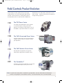
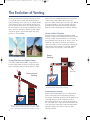
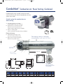
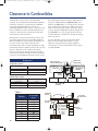
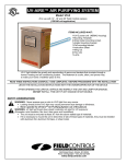
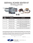
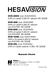
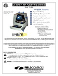
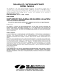
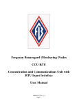
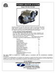
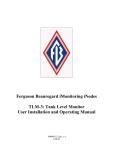
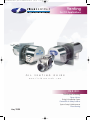
7137FCHVentGuideOil_New:7137FCHVentGuideOil
5/8/08
10:42 AM
Page 1
Venting
for Oil Applications
O I L
V E N T I N G
G U I D E
w w w . f i e l d c o n t r o l s . c o m
INSIDE:
The Evolution of Venting
Power Venters
Sizing & Installation Specs
Control Kits & Safety Switches
System Setup & Maintenance
Direct Venting
May 2008
7137FCHVentGuideOil_New:7137FCHVentGuideOil
5/8/08
10:42 AM
Page 3
Field Controls Product Evolution
Field Controls has made products for the oil and gas
heating markets since 1927. Starting with draft controls
for large, commercial furnaces, Field quickly began to
develop products for the residential market. Today Field
1982
Controls focuses on draft control, combustion air, and
power venting … products that improve and support oil
and gas burning equipment.
The PVO Power Venter
The indoor mounted PVO Power Venter provides
an economical power venting system for oil
appliances. All controls are built into these units. A
Vent Hood is required to terminate the vent system.
1988
The SWG Aluminized Power Venter
Combined motor, blower and vent hood into one,
compact, easy to install unit. Primarily used with
gas applications.
1993
The SWG Stainless Power Venter
Developed for oil applications. Designed to
withstand New England and Canadian winters.
2007
The ComboVent™
All stainless unit includes combustion air connection
and extendable body for walls up to 14" thick.
Note: A separate Gas Venting Guide is available for gas applications. For more information on Field Controls
products, wiring diagrams and installation manuals, visit www.fieldcontrols.com or call 252.522.3031.
3
7137FCHVentGuideOil_New:7137FCHVentGuideOil
5/8/08
10:42 AM
Page 4
The Evolution of Venting
As long as people have used fire to heat, it has been
necessary to vent the smoke and combustion gases
from the dwelling. Since heat rises, the natural solution
was to allow the gases to vent through the roof via a
hole or chimney. For centuries, this "natural draft" style
of venting has been the accepted standard for venting
stoves, furnaces and boilers. Whether fired by wood,
coal, oil or gas, this system worked well and, when
possible, is still used today.
homes restrict the infiltration of outside air which also
restricts natural draft. Higher efficiency furnaces
generate "cooler" exhaust gases which are more difficult
to exhaust naturally as well. These factors led to the
development of a mechanical method of venting to
properly remove combustion gases from the dwelling.
Homes without Chimneys
Electric heat grew in popularity through the 1960's
and 70's, resulting in the construction of homes without
chimneys. Today, many homeowners are converting
their heat from electric to gas or oil. In these cases, the
contractor is faced with a challenge of venting the
equipment. Choices include constructing a chimney or
mechanically venting through the sidewall. Sidewall
venting is much less expensive, easier and faster.
Power
Venting
Energy Efficiency and Tighter Homes
In the late 1970's and early 80's, energy efficiency
became a top priority in America resulting in tighter
homes and more efficient heating equipment. Tight
Vent
Gases Out
Conventional
Venting
Oil Burner
Mechanically pulls gases through the sidewall, saving
the cost and space required for a chimney.
Deteriorating Chimneys
Oil Burner
Hot air rises. As long as a chimney exists, it is in good
condition and the combustion gases are warm enough
to rise naturally, this method can be effective and safe.
4
Another factor contributing to the use and growth of
power venting has been the deteriorating chimney.
Oil and gas combustion generate acid rich gas that can
eventually destroy a clay or masonry chimney. A
deteriorating chimney can be relined with metal duct,
but even metal duct is subject to rust and corrosion due
to the destructive nature of the acid and condensation.
Sidewall venting is safer and less expensive than
relining a chimney.
7137FCHVentGuideOil_New:7137FCHVentGuideOil
5/8/08
10:43 AM
Page 5
The Evolution of Venting
Direct Venting
Power Venting
with Combustion Air
In response to the growing use of direct vent burners, Field
Controls developed the Field Direct™ Venting System in
2005. The FDVS is included as part of the original
equipment on many popular brands of furnaces and
boilers and is not yet available through wholesale
distributors. The FDVS includes a double wall system that
simultaneously vents combustion gases while bringing
combustion air to the burner.
Vent
Gases Out
Combustion Air
Oil Burner
Direct
Venting
Combustion
Air
Provides fresh air for combustion while exhausting
combustion gases through one hole in sidewall.
Power Venting
In the early 1980's, Field Controls introduced the PVO
power venter. It was an indoor mounted power venter
connected to the outside wall via a vent hood. The PVE,
PVO and PVG series venters are still popular and in use
today. In 1988, Field introduced and patented the outdoor
mounted SWG power venter. It combined the motor,
blower, and vent hood in one convenient package.
The double wall pipe allows for near-zero clearance to
combustibles. The SWG is available aluminized for gas
applications and stainless steel for oil use. In 2007,
Field introduced the ComboVent™ Power Venter.
The ComboVent is all stainless and includes a
combustion air connection and an extendable body for
walls up to 14 inches thick.
Vent
Gases Out
Oil Burner
The fan is a part of the furnace and forces
combustion gases out the sidewall via double-walled
sealed pipe. Combustion air is pulled into the
structure simultaneously.
5
7137FCHVentGuideOil_New:7137FCHVentGuideOil
5/8/08
10:43 AM
Page 6
ComboVent™ Combustion Air. Power Venting. Combined.
Introducing the most versatile, easiest to install,
easiest to service, all inclusive combustion air/vent
system ever made.
NEW
A total system for combustion air
and venting.
A - Telescoping stainless steel body
Accommodates walls up to 14” thick
B - Combustion air connection included
Provides fresh air directly to burner
Coupler rotates 360° for easy installation
C - Two piece backing plate
Can be mounted at any point during installation
Easier to Service
D - Slotted hood with larger screws
Saves time during annual service
E - Quick-connect electrical coupling
Allows for easy motor access
Telescoping stainless steel body
Accommodates walls up to 14" thick
A
D
Stainless Steel
E
Slotted hood with
larger screws
Up to14"
Quick-connect
electrical coupling
B
C
Two piece backing plate
•Combustion air
connection included
•Coupler rotates 360° for
easy installation
Specifications and Dimensions
Model
CV-4
CV-5
6
Volts
Hz
Amps
Watts
RPM
Thermal
Protection
A
B
C
115
115
60
60
1.7
1.3
138
144
3000
3100
YES
YES
4"
5"
6"
7"
11 ⁄4"-17 ⁄4"
11 3⁄4"-17 3⁄4"
3
3
D
E
F
9 ⁄2"
10 3⁄4"
9"
12"
9"
12 1⁄4"
1
7137FCHVentGuideOil_New:7137FCHVentGuideOil
5/8/08
10:44 AM
Page 7
SWG Stainless Power Venter
Benefits of the SWG Power Venter include:
•
100% negative pressure in the vent pipe for
maximum safety.
•
Standard galvanized pipe can be used instead
of expensive stainless steel.
•
No need to seal vent pipe joints, saving time
and money.
•
Significantly longer vent lengths than positive
pressure, direct vent systems.
•
The SWG is recommended by major heating
appliance manufacturers.
The SWG must be sized to match the appliance or
appliances’ input firing rate. Most firing rates are
published in the manufacturer’s installation
manual. SWGs must be installed with a CK
Control Kit to ensure proper listing and safe,
efficient venting.
Replacement Motor Kit and Stainless Steel Model shown.
Note: SWG-4HD, 5 & 6 Motor Kits include a stainless steel
blower wheel for better performance and extended life.
F
A B
D
C
E
Specifications and Dimensions
Model
A
B
C
D
E
F
SWG-3
3"
5"
9 ⁄16"
1
8 ⁄2"
5
7 ⁄8"
9 3⁄16"
SWG-4HD
4"
6"
11 ⁄4"
1
9 ⁄2"
9"
9"
SWG-4HDs
4"
6"
11 ⁄4"
1
9 ⁄2"
11"
11 1⁄2"
SWG-5
5"
7"
11 ⁄4"
10 ⁄4"
12"
12 1⁄4"
SWG-5s
5"
7"
11 3⁄4"
10 1⁄2"
12"
12 1⁄2"
SWG-6
6"
8"
11 ⁄4"
10 ⁄4"
12"
12 1⁄4"
SWG-6s
6"
8"
11 3⁄4"
10 1⁄2"
12"
12 1⁄2"
SWG-8
8"
10"
11 ⁄4"
11 ⁄8"
13"
14 1⁄4"
SWG-10
10"
14"
19 1⁄2"
24"
20"
21"
SWG-12
12"
16"
19 ⁄2"
25"
22"
23"
SWG-14
14"
18"
19 1⁄2"
26"
24"
25"
1
3
3
3
3
3
1
3
3
7
NOTE: Control Kits are required for operation of the SWG. “s” Designates stainless steel model (recommended for oil applications).
7
7137FCHVentGuideOil_New:7137FCHVentGuideOil
5/8/08
10:44 AM
Page 8
Sizing The Power Venter
Size the Power Venter based on the input firing rate of the
appliance. If the power venter is being used to vent multiple
appliances, add the input firing rates for each appliance and
use that total to size the venter. Knowing the total input GPH for
oil, the venter can be sized from Table 1. Select the venter rated
closest to the total input GPH for installation. If the input of the
appliance is higher than the max allowable for that size Power
Venter, move to the next larger size.
Do not select a venter with a maximum GPH lower than the
appliance. The equivalent feet of vent pipe for the installation
must be calculated. Based on the vent pipe diameter to be used,
compare the calculated equivalent feet of vent pipe with the
maximum equivalent feet allowable for the venter (see Table 1).
If the calculated equivalent feet is greater than that allowed for
the venter, increase the diameter of the vent pipe to be used and
refer to the table or use the next larger size Power Venter.
SWG and ComboVent (CV)
Table 1-Sizing The Venter (Use Maximum GPH Input)
MAX*
OIL GPH
INPUT
100psi
MAX*
OIL GPH
INPUT
140psi
SWG-3
N/A
N/A
SWG-4HD, 4HDs, CV-4
1.10
.90
SWG-5, 5s, CV-5
1.85
1.55
SWG-6, 6s
2.65
2.25
SWG-8
4.75
4.0
SWG-10
9
7.5
SWG-12
13.5
11.5
SWG-14
21
17.75
MODEL
Maximum Equivalent Feet of Vent Pipe
AT MAX
GPH INPUT
AT 60% OF MAX
GPH INPUT
21
50
35
65
100
100
16
51
95
100
28
68
100
26
51
70
10
30
75
16
40
86
8
18
35
80
100
100
100
100
100
44
100
100
100
78
100
100
72
100
100
100
100
100
100
100
100
85
100
100
* Select venter according to the actual rated maximum GPH input. ComboVent GPH ratings at 100 psi.
Do not exceed maximum oil GPH input. For multiple venting system applications add the input for each.
Unit sizing may vary depending on specific application. Consult your dealer or factory representative for
the proper sizing for your particular application.
Note: In Table 1, the maximum equivalent footage allowable for the vent pipe is given for two points,
the maximum GPH venting capacity and at 60% of the maximum. This allows for estimating values
between the two given points.
8
VENT
PIPE SIZE
3"
4"
4"
5"
6"
7"
4"
5"
6"
7"
5"
6"
7"
7"
8"
9"
8"
10"
12"
10"
12"
14"
12"
14"
16"
7137FCHVentGuideOil_New:7137FCHVentGuideOil
5/8/08
10:44 AM
Page 9
Locating The Power Venter
Calculating Equivalent Feet of a Vent System
Using a Reducer/Increaser
Procedure
Step 1 2-90° Elbows (4") = 14 Ft.
Step 2 10-2 Ft. Lengths of 4" Pipe = 20 Ft.
Step 3 Total Equivalent Feet = 14 Ft. + 20 Ft. = 34 Ft.
Table 2
Vent Pipe
Fittings
Tee
Y-Connection
90° Elbow
45° Elbow
Small Pipe Size
Large Pipe Size
1. Determine the total equivalent feet for each type of fitting
used in the venting system from Table 2.
2. Calculate the total feet for the straight lengths of pipe.
3. Add the equivalent feet of the fittings to the total amount of
feet of straight length pipe. This will approximate the total
equivalent feet of the vent system.
Example: System Pipe Size = 4"
Vent Pipe Diameter
3" 4" 5" 6" 7" 8" 9"
19 25 31 38 44 50 56
10 13 16 20 23 26 29
5
7
9 11 12 14 16
3
4
4
5
6
7
8
10"
63
32
18
9
12"
75
39
21
10
14"
89
45
25
13
3"
4"
5"
6"
7"
8"
9"
10"
12"
14"
16"
18"
20"
3"
0
2
4
5
6
7
7
8
8
9
9
9
9
4"
5"
6"
7"
8"
9"
10"
12"
14"
0
2
4
5
7
8
8
10
10
11
11
12
0
2
4
6
7
8
10
12
12
13
14
0
1
3
5
6
8
10
11
12
13
0
2
4
6
9
12
14
15
16
0
2 0
4 2 0
8 6 4 0
11 9 8 3 0
13 13 11 8 3
15 15 14 11 7
17 17 17 15 11
To estimate the equivalent foot length of the Reducer/Increaser chart, find
the figure at the intersection of the small pipe size and the large pipe size.
Terminal Locations of a Vent System
Location of the termination of the venting system should
comply with the National Fuel Gas Code, ANSI Z223.1,
manufacturer’s recommendations and/or applicable local
codes. See diagram for typical terminal locations.
A. The exit termination of a mechanical draft system
must not be less than 7’ above grade when located
adjacent to a public walkway.*
B.
The venting systems, with the exception of direct vent
appliances, must terminate at least 4’ below, 4’
horizontally, or 1’ above any door, window or gravity
air inlet into the building.
C. A venting system must terminate at least 3’ above any
forced air inlet located within 10’.
D. The bottom of the vent terminal must be located at
least 1’ above finished grade.**
B
A
C
D
B
F
E.
The vent termination should not be mounted directly
above or within 3’ horizontally from an oil tank vent
or gas meter (not shown in diagram).
F.
The vent termination point must not be installed closer
than 3’ from an inside corner of an L-shaped structure.
G. For basement installations where a window well must
be used or in installations where the vent terminal
cannot be mounted to maintain the minimum 12"
clearance above grade, use a Field Vent Riser™. The
Vent Riser ensures the vent termination is above grade
or the snow line and is in compliance with local codes
(not shown in diagram).
* 10" or larger should be 10’ minimum above public walkway.
** 10" or larger should be 4‘ above finished grade.
9
7137FCHVentGuideOil_New:7137FCHVentGuideOil
5/8/08
10:45 AM
Page 10
Clearance to Combustibles
If mounting the venting system near combustible
materials, refer to Diagram A for allowable installation
clearances. Clearances are based on an installation
using single wall galvanized steel vent pipe. If
manufactured double wall vent pipe is required or used
for the installation, clearance should be based on the
vent pipe’s rated clearance. Always check local code
requirements for code restrictions.
Routing of the vent system and clearances for the vent
pipe may be planned once the termination location is
determined. Route the vent pipe from the appliance to
the venter using as few elbows as possible. The
horizontal section of the vent pipe should have a slight
upward slope from the appliance to the venter. The vent
pipe size (diameter) can be smaller than a typical
chimney vented system and still overcome the higher
pressure losses because the power venter mechanically
creates the required draft or air flow to vent the system.
For estimating the minimum vent pipe diameter for an
oil system, multiply GPH by 140,000 BTU/GAL, then
divide by 12,600 BTU/sq. in. This will give the minimum
cross sectional area required. (See Table 3 for area to
diameter conversion.) For multiple equipment venting
systems, divide the total BTU/hr. input for all appliances
by 9,300 BTU/sq. in. This will give you the minimum
vent pipe diameter needed for the common breaching
of the vent system.
As a rule of thumb, size the vent pipe to the outlet
diameter of the heating equipment for a single
appliance venting system. For multiple appliance
venting systems, use the outlet diameter of the largest
unit and add 50%.
Diagram A
METAL LINING FOR
550°F-400°F INPUT TEMP.
Single Pipe System
Allowable Inlet Temperature
Clearance (B)
400ºF or Less
550ºF or Less
550ºF or Less
3" min.
4" min.
3" min.*
FLOOR JOIST
A
B
SQUARE HOLE
THROUGH WALL
B
A
B
A
COMBUSTIBLE
MATERIAL
B-VENT
ELBOW
Double Pipe System
Allowable Inlet Temperature
Clearance (A)
400ºF or Less
550ºF or Less
550ºF or Less
.5" min.
1" min.
.5" min.*
INPUT TEMP.
LOCATION
* With galvanized sheet metal liner or equivalent
Table 3
10
Pipe Size
Nominal
Cross-Sectional Area
Sq. Inches
3"
4"
5"
6"
7"
8"
9"
10"
12"
14"
7
13
20
28
38
50
64
79
113
154
COMBUSTIBLE
MATERIAL
FLOOR JOIST
A B
FLOOR
SWG SERIES
POWER VENTER
INPUT TEMP.
LOCATION
OUTER PIPE
EXTENSION
END PIPE COVER
FROM SWG UNIT
B-VENT or
L-VENT
ELBOW
BLOCK
FOUNDATION
7137FCHVentGuideOil_New:7137FCHVentGuideOil
5/8/08
10:45 AM
Page 11
Control Kits
Control Kits
✓
✓
CK-62
All oil-fired systems. Has thermally activated post purge.
✓
✓
CK-63
All oil-fired systems.
(May require optional delay oil valve for simultaneous burner operation.)
✓
✓
Applications
RJR-6 120V Relay
All oil-fired systems. Has adjustable electronic post purge.
Model
Adjustable Electronic
Post Purge
Secondary Safety Switch
CK-61
Control Kit*
Thermal Post Purge
Draft Proving Switch
Control Kits (CK) control the operation of Power
Venters. See the chart below to select the proper
kit for your application.
✓
✓
✓
✓
✓
✓
* Control Kits are ETL approved accessories when used in conjunction with the SWG and ComboVent Power Venters.
Control Kit Installation:
CK-63 remote mounted. For use with
120 VAC oil-fired systems. Electronic
post purge is included (shown with
cover off). CK kits can be mounted up
to 100 feet from venter.
PPC-4 Post Purge
Thermal Safety Switch
Our thermal safety switches efficiently detect flue gas spillage
due to a blocked flue, continuous down drafting or
inadequate draft condition. With the safety switch wired in
series with the burner circuit, the switch will de-energize the
system’s burner or burner control once it senses the spillage
of hot flue gases. It will not allow the burner to restart until
the switch has been manually reset.
Model
Part No.
WMO-1
46086900
Contact Load-Rating Load-Rating
Normally Closed Switch Switch Type
Material (Amps)
(Volts)
Silver
10 Amps
120 AC
200°F
M
SPDT
Application
Manual reset. Designed for use with power
venting and chimney vented systems for
oil-fired applications.
11
7137FCHVentGuideOil_New:7137FCHVentGuideOil
5/8/08
10:45 AM
Page 12
System Setup
SYSTEM SETUP:
Figure 1 shows a typical oil-fired appliance and the expected ranges of several readings taken at various locations
in the system. Note: If a vent pipe reducer is required, use a smooth walled gradual reducer. Place it at the venter
inlet as shown in Figure 1.
1. Set the choke plate in the power venter, or extension kit, to its full open position. Set the draft control adjustment
weight to its midpoint position.
2. Adjust the thermostat so that the unit will run continuously. Allow the unit to operate for 5 to 10 minutes to ensure
stack temperature stabilization.
3. Find out the manufacturer’s recommended over-fire or breeching draft. Close the choke plate on the SWG until the
draft above the draft control reads approximately 0.04” w.c. greater than the recommended breeching draft.
Example: If the appliance manufacturer recommends a 0.02” breech draft, adjust the choke plate to get an
approximate 0.06” draft above the draft control.
4. Adjust the barometric draft control to obtain the manufacturer’s recommended draft over-fire or at the breech. The
draft control gate should be open approximately half its full swing during normal operation. This allows the gate to
swing open or closed depending on changes in atmospheric pressure or operating conditions.
5. If the proper draft cannot be obtained at the breech or if the gate does not open as described, then adjust the choke
plate in the SWG to reduce or increase the airflow. Re-adjust the draft control to obtain the required draft, since
moving the choke plate will change the system draft.
Procedure for adjusting the pressure switch
• Turn pressure switch adjustment clockwise until the burner quits.
• Turn counter-clockwise slowly until the burner starts.
• Turn an additional 1/4 to 1/2 turn counter-clockwise.
Note: Every installation will require unique pressure switch adjustment.
Figure 1
12
7137FCHVentGuideOil_New:7137FCHVentGuideOil
5/8/08
10:45 AM
Page 13
System Setup and Maintenance
6. Once proper draft is achieved, measure CO2 and smoke level. If necessary, adjust the intake airflow at the burner
to obtain the highest possible CO2 reading with a zero smoke reading. As the intake airflow is increased or
decreased, the draft may change. Repeat steps 3 through 6 to re-adjust the draft control and choke plate before
attempting any other adjustments.
7. Measure combustion efficiency and exhaust gas temperature at the venter inlet. Combustion efficiency should be
adjusted to maximum attainable at zero smoke. Exhaust gas temperature at the venter inlet should range between
200ºF and 550ºF.
8. If maximum efficiency and zero smoke yields a temperature below 200ºF at the inlet to the venter, the following
suggestions must be considered.
A. Use a larger oil nozzle or higher oil pump pressure to raise the firing rate of the burner. Repeat
steps 3 through 7 until all combustion parameters are within the specified ranges.
B. Reduce the length of the duct from the appliance to the venter which will increase the venter
inlet temperature.
C. Insulate the vent pipe to minimize heat loss.
D. Seal the vent pipe joints to reduce uncontrolled dilution air.
TESTING:
1. The thermostat (wall thermostat, or aquastat) calls for heat, starting venter motor.
2. After the venter motor has come up to speed, the pressure switch closes. This closes the circuit to the burner and
allows the burner to operate. This occurs in approximately 1 to 2 seconds.
3. After the heating requirement is satisfied, the thermostat circuit opens and deactivates the burner and power
venter circuit.
4. Oil venting systems require a post purge device. During the post purge cycle, the venter operates for a period after
the burner has shut off. This is to purge the remaining flue gases and to cool the combustion chamber. Typical post
purge times are 3 to 5 minutes. Longer purge times may be required depending on system installation.
SWG Super Lube
ANNUAL MAINTENANCE:
1. Motor: Inspect the motor once a year; it should rotate freely.
To prolong the life of the motor, lubricate with six drops of
SWG Super Lube, Part #46226200, annually. Use of any
other type of lubricant may cause premature motor failure.
2. Wheel: Inspect the venter wheel annually to clear any soot,
ash, or coating which inhibits either rotation or air flow.
Remove all foreign materials before operating.
• Oil motor and fan shaft with
SWG Super Lube annually
• Works in conditions of -40° to
300° (F)
• Synthetic lubricant which
maintains specified viscosity
• Use of any other lubricant may
cause premature failure
3. Vent System: Inspect all vent connections annually for looseness, for evidence of corrosion, and for flue gas leakage.
Replace, seal or tighten pipe connections if necessary. Check the venter choke plate to ensure it is secured in place.
Check the barometric draft control to ensure the gate swings freely.
4. System Safety Devices: With the heating system operating, disconnect the pressure sensing tube from the pressure
switch on the CK Kit. This should stop the burner operation. Re-connecting the tube should relight the burner.
13
7137FCHVentGuideOil_New:7137FCHVentGuideOil
5/8/08
10:46 AM
Page 14
FieldDirect™ Venting System
Benefits of FieldDirect Venting System
• No adverse reactions to direct wind loads up
to 50mph.
• Burner efficiency actually improves under direct
wind load.
• Decreased chance of exhaust gases recirculating
into the structure.
• Virtually impossible for snow to block the air intake.
• Stainless 316 construction.
• Inner pipe is angled to drain condensation outside.
• Stainless, seam welded inner pipe reduces
potential of corrosion and leakage.
• Exhaust angle reduces migration.
• Nozzle configuration accelerates combustion gases
away from the structure.
Patent Pending Design
How FieldDirect Venting Systems Work
Allows combustion air to enter from the
top of the unit.
Fresh Air In
Combustion gases are accelerated at
the nozzle and exit the structure at an
optimal angle.
Combustion
Air
Combustion
Gases Out
Vent
Gases Out
Installation Advantages of FieldDirect Venting System
• Installs with one hole through the wall.
• Zero clearance to combustibles.
• Seamless inner pipe, heavy-duty clamps,
and sealant prevent leakage of vent gases.
• Combustion Air Tee can be rotated within
180 degrees.
14
7137FCHVentGuideOil_New:7137FCHVentGuideOil
5/8/08
10:46 AM
Page 16
www.fieldcontrols.com
Field Controls, LLC | www.fieldcontrols.com | 2630 Airport Road | Kinston, NC 28504 | TEL: 252.522.3031 | FAX: 252.522.0214
©2008 Field Controls
form# 4318
Printed in U.S.A.(CP08)