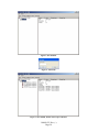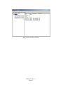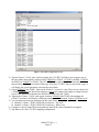
1
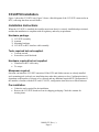
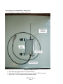
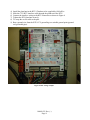
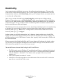
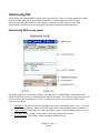
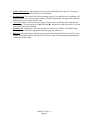
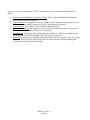
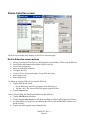
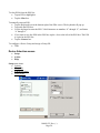
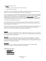
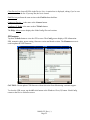
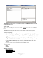
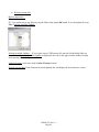
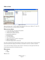
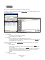
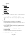
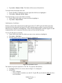
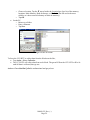
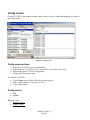
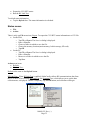
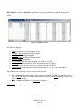
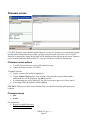
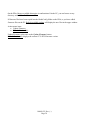
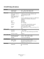
Ferguson Beauregard iMonitoring iNodes
CCU-RTU
Concentration and Communications Unit with
RTU Input Interface
User Manual
100469-22, Rev. (-)
Page 1
Table of Contents
Introduction............................................................................................................................................. 4
What is an iMonitoring CCU-RTU? .............................................................................................................. 4
Principal features of the CCU-RTU:.............................................................................................................. 4
CCU-RTU Installation............................................................................................................................ 6
Installation Instructions................................................................................................................................... 6
Hardware package. ......................................................................................................................................................... 6
Tools required but not supplied...................................................................................................................................... 6
Hardware required but not supplied. .............................................................................................................................. 6
Manpower required. ....................................................................................................................................................... 6
Pre-installation. .............................................................................................................................................................. 6
Assembly and installation sequence............................................................................................................................... 7
Configuring the CCU-RTU............................................................................................................................................ 9
Configuring iNodes for collection............................................................................................................................. 9
CCU-RTU data mapping......................................................................................................................................... 12
iNodeConfig .......................................................................................................................................... 14
iNodeConfig-PDA........................................................................................................................................... 15
iNodeConfig PDA screen layout.................................................................................................................................. 15
iNodeConfig-PC ............................................................................................................................................. 17
iNodeConfig PC screen layout ..................................................................................................................................... 17
Device Selection screen .................................................................................................................................. 19
Device Selection screen actions ................................................................................................................................... 19
Device Selection menus ............................................................................................................................................... 20
CFR screens............................................................................................................................................................. 22
Config menus...................................................................................................................................................... 23
Firmware menus ................................................................................................................................................. 23
Sites screen...................................................................................................................................................... 25
Sites screen actions ...................................................................................................................................................... 25
Sites menus .................................................................................................................................................................. 25
Config screen. ................................................................................................................................................. 30
Config screen actions ................................................................................................................................................... 30
Config menus ............................................................................................................................................................... 30
Collection screen ............................................................................................................................................ 32
Collection screen actions.............................................................................................................................................. 32
Collection menus.......................................................................................................................................................... 32
Status screen ................................................................................................................................................... 34
Status screen actions..................................................................................................................................................... 34
Status menus................................................................................................................................................................. 35
RF Link Test .................................................................................................................................................. 36
Firmware screen............................................................................................................................................. 37
Firmware screen actions............................................................................................................................................... 37
Firmware menus........................................................................................................................................................... 37
CCU-RTU Specifications...................................................................................................................... 39
100469-22, Rev. (-)
Page 2
List of Figures
Figure 1. CCU-RTU................................................................................................................................. 4
Figure 2. CCU-RTU block diagram......................................................................................................... 5
Figure 3. CCU-RTU side view. ............................................................................................................... 7
Figure 4. RTU wiring example. ............................................................................................................... 8
Figure 5. Site disabled............................................................................................................................ 10
Figure 6. Add iNode. ............................................................................................................................. 10
Figure 7. Site enabled, iNodes entered, pre-collection. ......................................................................... 10
Figure 8. Sites screen post-collection. ................................................................................................... 11
Figure 9. CCU-RTU configuration screen............................................................................................. 13
Figure 10. Sites screen. .......................................................................................................................... 25
Figure 11. File Open screens. ................................................................................................................ 26
Figure 12. Link statistics screens. .......................................................................................................... 28
Figure 13. Save As screens. ................................................................................................................... 29
Figure 14. Config screens. ..................................................................................................................... 30
Figure 15. Collection screens................................................................................................................. 32
Figure 16. Status screens........................................................................................................................ 34
Figure 17. RF link test data.................................................................................................................... 36
List of Tables
Table 1. iNode types and mapping parameters..................................................................................... 12
Table 2. Mapping chart example. .......................................................................................................... 12
100469-22, Rev. (-)
Page 3
Introduction.
What is an iMonitoring CCU-RTU?
Figure 1. CCU-RTU.
Ferguson Beauregard’s iNode Collection and Communications Unit with RTU Interface (CCU-RTU)
is a version of the iNodes CCU which collects data from iNodes sensors. The CCU-RTU then maps
the data to analog and digital outputs compatible with an RTU’s analog and digital inputs.
The CCU-RTU is significantly different from the standard iNodes CCU:
•
•
•
•
It is powered by the RTU.
It has no uplink modem (e.g. satellite modem), since data is forwarded by the RTU.
Collected data from iNodes sensors are mapped to RTU-compatible analog outputs.
Alarms from iNodes sensors are mapped to RTU-compatible digital outputs.
Principal features of the CCU-RTU:
•
•
•
•
•
•
Maps collected iNodes data and alarms to analog and digital outputs compatible with industry
standard RTUs.
Small, integrated package includes processing, data storage and radio communications.
Communicates with any Compact Flash Radio-enabled PC, including laptops, pen tablet PCs
and PDAs.
Rugged IP65-certified enclosure.
Field configurable and upgradeable.
Low cost.
100469-22, Rev. (-)
Page 4
Figure 2. CCU-RTU block diagram.
100469-22, Rev. (-)
Page 5
CCU-RTU Installation.
Figure 1 shows the CCU-RTU unit. Figure 2 shows a block diagram of the CCU-RTU connected to an
RTU, collecting data from several iNodes.
Installation Instructions
When the CCU-RTU is installed, the installer must insure that it is correctly installed and provisioned,
and that the installation is compliant with all regulatory and safety requirements.
Hardware package.
1)
2)
3)
4)
CCU-RTU assembly.
Antenna.
Mounting hardware.
CCU-RTU to RTU interface cable assembly.
Tools required but not supplied.
•
•
Crescent wrench.
Screwdriver, small slot head.
Hardware required but not supplied.
•
•
Gland nut for RTU cable entry.
Tie wraps.
Manpower required.
One man can install the CCU-RTU unassisted. If the RTU and iNodes sensors are already installed
and a mounting pole is already set, installation time takes thirty minutes or less. Configuration time is
dependent on the number of sensors to be collected and any additional required RTU configuration. If
the installer is familiar with the RTU and CCU-RTU, configuration time takes ten to fifteen minutes.
Pre-installation.
•
•
Gather the tools required for the installation.
Remove the CCU-RTU hardware from its shipping packaging. Check the contents for
missing items.
100469-22, Rev. (-)
Page 6
Assembly and installation sequence.
See the side view of the CCU-RTU in Figure 3.
Figure 3. CCU-RTU side view.
1) Attach the pole mounts to the CCU-RTU enclosure.
2) Mount the CCU-RTU enclosure to the pole on which the RTU is mounted.
3) Screw the CCU-RTU antenna onto the antenna mount.
100469-22, Rev. (-)
Page 7
4)
5)
6)
7)
8)
9)
Install the gland nut in the RTU. Gland nut to be supplied by field office.
Slide the CCU-RTU interface cable through the gland nut in the RTU.
Connect the interface wiring to the RTU connectors as shown in Figure 4.
Tighten the RTU gland nut securely.
Tie wrap the excess cable to the pole.
Run a ground wire from the RTU-CCU ground lug to a suitable ground point (ground
rod, grounded pipe).
Figure 4. RTU wiring example.
100469-22, Rev. (-)
Page 8
Configuring the CCU-RTU.
Connecting a CCU-RTU to an RTU requires configuration of both units. RTU configuration is
dependent on the particular RTU. Refer to your RTU documentation for instructions on configuring
inputs, mapping, etc. The Ferguson Beauregard RTU5000 is shown in the following configuration
example.
The CCU-RTU is configured with Ferguson Beauregard’s iNodeConfig software. iNodeConfig will be
discussed in detail in the following sections. For now we will use an example where a CCU-RTU will
collect data from four iNodes and send that data to an RTU.
Configuring iNodes for collection.
Before the CCU-RTU can be configured, it must learn each sensor’s type, so that it can present the
correct options during configuration. The CCU-RTU supports the following iNode sensors:
•
•
•
•
•
•
TLM-1 (Tank Level Monitor, ultrasonic)
TLMe (Tank Level Monitor, ultrasonic)
TLM-3 (Tank Level Monitor, float)
WDS (Wireless Data Switch)
WPM (Wireless Pressure Monitor)
EFM (Electronic Flow Meter)
To configure the CCU-RTU,
1) Wire RTU power (+12VDC nominal) to CCU-RTU connector J8. (The board is silkscreened.
+12V and ground are clearly marked.)
2) After applying power, start iNodeConfig on your laptop or PDA.
3) Connect to the CCU-RTU.
4) Initially the Sites page (the first CCU-RTU page displayed) may be disabled as shown in Figure 5.
If so, enable the site by tapping Action > Enable Site.
5) Add the ESNs of all iNodes the CCU-RTU will collect, by tapping Action > Add iNode… An
entry box will pop up, shown in Figure 6. Enter the first iNode ESN and tap OK. Repeat this step
until you have entered all iNodes.
6) For the CCU-RTU to determine each iNode’s type, it must collect data from each iNode. NOTE:
All iNodes must be operating and in range of the CCU-RTU before collection.
7) Tap Action > Force Collection. A green LED on the CCU-RTU board will light. It will go out
after all data has been collected. Depending on the number of iNodes, this may take several
minutes.
8) When the LED goes out, tap Action > Refresh Site.. The device information in the righthand
window should now display the iNode type to the right of the iNode Name as shown in Figure 8.
You can now configure CCU-RTU data mapping.
100469-22, Rev. (-)
Page 9
Figure 5. Site disabled.
Figure 6. Add iNode.
Figure 7. Site enabled, iNodes entered, pre-collection.
100469-22, Rev. (-)
Page 10
Figure 8. Sites screen post-collection.
100469-22, Rev. (-)
Page 11
CCU-RTU data mapping.
To send iNode data to an RTU, the CCU-RTU must map the iNode data to its outputs. The CCU-RTU
has two output types: analog, which sends a 0.25 - 4.75VDC voltage proportional to the measured
value, and digital, which sends an off / on level. Analog outputs are used with parametric data such as
pressure or level. Digital outputs are used for alarm conditions. (The conditions required to generate an
alarm are individually configured on each iNode. Refer to the iNode’s User Manual for instructions on
configuring alarms.)
Before mapping iNode data to CCU-RTU channels, first decide which iNode data you want to map.
Table 1 lists each iNode type and the parameters which can be selected for each type.
Table 1. iNode types and mapping parameters.
iNode Type
EFM
TLM1 / TLMe
TLM3
WPM
WDS
Map parameters
• Static pressure
• Differential pressure
• Temperature
• Level
• Top level
• Water level
• Pressure (0-500 psig)
• Pressure (0-6000 psig)
• Temperature
• Flow rate
A chart like the example shown in Table 2 is a good method of organizing your channel mapping plan.
Table 2. Mapping chart example.
Channel
Analog 1
Analog 2
Analog 3
Analog 4
(etc.)
Digital 1
Digital 2
(etc.)
ESN
25000528
25000528
11511683
25000057
Type
TLM3
TLM3
WPM
TLM1
Parameter
Top level
Water level
Pressure (500)
Level
25000528
11511683
TLM3
WPM
Top level
Pressure (500)
To map iNode data to channels, use the following example.
1) Tap the Config tab. The Config screen will appear as shown in Figure 9. (Slide the vertical
slidebar down to see all the entries.) Notice that there are eight analog configuration items (iNode,
parameter) and four digital configuration items (iNode, parameter).
100469-22, Rev. (-)
Page 12
Figure 9. CCU-RTU configuration screen.
2) Tap the Channel 1 iNode value. In this example, the CCU-RTU will allow you to choose one of
the four iNodes from which it collected data: 25000528 (a TLM3), 11511683 (a WPM), 17500512
(an EFM2) or 25000057 (a TLM1). The CCU-RTU had to collect data from each of the iNodes
entered on the Sites page to learn its iNode type. Once the CCU-RTU knows each iNode’s type, it
will display the correct parameter selections for each iNode.
3) Choose 25000057 (the TLM1). Now tap the Channel 1 parameter value. There are two choices for
a TLM1: Unassigned (no data will be output), or Level (the channel will output a voltage between
0 and 5VDC which corresponds to the fluid level measured by the TLM1).
4) Tapping the Channel 1 iNode value again, choosing 25000528 (the TLM3), then tapping the
Channel 1 parameter will display a different parameter set: Unassigned, Top level or Water level.
5) You can map more than one parameter for the same iNode. For example, you could choose:
a) Channel 1: iNode = TLM3 (25000528), Parameter = Top level.
b) Channel 2: iNode = TLM3 (25000528), Parameter = Water level.
6) Continue to choose iNode ESNs and parameters until all the desired channels are mapped.
7) Tap Save to save the CCU-RTU mapping configuration.
100469-22, Rev. (-)
Page 13
iNodeConfig
Local communication with iNodes is necessary for configuration and maintenance. The same radio
system used to collect data from iNodes by the CCU also supports local communications. The local
communications software, called iNodeConfig, allows you to configure iNodes, set controls and view
or save data and configurations.
There are two versions of iNodeConfig: iNodeConfig-PDA, which runs on all PDAs with the
Windows CE operating system, and iNodeConfig-PC, which runs on laptops and PCs with Windows
2000, NT or XP. Both versions require an iMonitoring Compact Flash Radio card (CFR) installed in a
Compact Flash port. The two versions are made as similar as possible to minimize confusion if you
have to switch between a PDA and a laptop.
The following sections are presented, in most cases, by starting at the left most user screen and moving
to the right, one screen at a time. Each user screen as shown on the iNodeConfig screen toolbar is
denoted by bold type, e.g. “Data screen”. Configuration or selection items within each screen are
denoted by bold type, e.g. “Configure”.
In these sections you will be be instructed to “tap” a button or location on the screen. On the PDA,
tapping will mean actually tapping the button or location with the PDA stylus. On PCs, tapping will
mean moving the cursor over the button or location, then “tapping” with a mouse pad or clicking with
the left mouse button.
Wherever practical, the iNodeConfig PDA and PC screen figures will be shown side by side, so that
you can easily see the similarities and differences between them. In larger screens, the PDA screen
will be shown first and the PC screen will be shown second.
The main differences between iNodeConfig for the PC and PDA are:
•
•
•
The PDA version uses the Windows CE standard tools and features, particularly the keyboard
icon and OK button at the top right of the screen. The PC version uses the Windows standard
tools: the Minimize – Maximize – Close buttons at the top right of the screen, sizeable
windows, etc.
There is no keyboard icon in the PC version.
In the PDA version, the page tabs are across the bottom of the screen. In the PC version, the
page tabs are across the top of the screen.
100469-22, Rev. (-)
Page 14
iNodeConfig-PDA
iNodeConfig uses about 800KB of storage space on your PDA. There is no setup application; simply
copy the iNodeConfig fileset into a folder on the PDA. Use File Explorer to browse to the
iNodeConfig folder and touch the “iNodeConfig” icon to start iNodeConfig. See your PDA
documentation for instructions on copying files to folders and creating start menu icons.
iNodeConfig PDA screen layout
All iNodeConfig PDA screens have similar views and tools. To understand the instructions in the
iNodeConfig PDA section, you should become familiar with them. The Firmware page, which you can
choose to view after connecting to a TLM-3, contains most of the views and tools, which will be
referred to as follows:
•
•
•
OK button: The white circle at the top right of the screen containing the letters “ok”. If you tap
this button on this page, iNodeConfig will return to the Connection page (more on this later).
Upper window: Some pages have only one window; others, like the Firmware page, have two.
The upper window usually contains one or more items that can be selected.
Lower window: This window usually contains information items.
100469-22, Rev. (-)
Page 15
•
•
•
•
•
Update Firmware box: Most pages have one or more action boxes like this one. If you tap a
box, the action described by the box text is performed.
Keyboard icon: This is part of the PDA operating system. If you tap this icon, a keyboard will
pop up to allow you to enter text and numbers. iNodeConfig usually will pop up the keyboard
automatically if you tap an editable value.
Tab arrows: There is a tab to select each page. In most cases, not all tabs can be displayed at
the same time. You can tap the left (◄) and right (►) tab arrows to slide the tab set so you can
locate the tab you want to choose.
Firmware tab: Eight pages can be chosen after you connect to a TLM-3 with iNodeConfig.
These pages are chosen by tapping the tab of the page you want to see.
File menu: Most pages have pull-up menus, located at the bottom left of the screen. If you tap
a menu, one or more choices will pop up. File choices relate to importing and exporting types
of files into iNodeConfig.
100469-22, Rev. (-)
Page 16
iNodeConfig-PC
iNodeConfig uses about 1.5MB of storage space on your PC. A setup application is used to install
iNodeConfig on your PC. After installation, use File Explorer to browse to the iNodeConfig folder and
tap the “iNodeConfig.exe” icon to start iNodeConfig. You may want to copy and paste the icon as a
shortcut to your laptop’s desktop for easier access to the program.
iNodeConfig PC screen layout
All iNodeConfig PC screens have similar views and tools. To understand the instructions in the
iNodeConfig section, you should become familiar with them. The Firmware page, which you can
100469-22, Rev. (-)
Page 17
choose to view after connecting to a TLM-3, contains most of the views and tools, referred to as
follows:
•
•
•
•
•
•
Windows buttons (Minimize, Maximize, Close): These are the standard Windows buttons.
They behave as in other programs.
Upper window: Some pages have only one window; others, like the Firmware page, have two.
The upper window usually contains one or more items that can be selected.
Lower window: This window usually contains information items.
Update Firmware box: Most pages have one or more action boxes like this one. If you tap a
box, the action described by the box text is performed.
Firmware tab: Eight pages can be chosen after you connect to a TLM-3 with iNodeConfig.
These pages are chosen by tapping the tab of the page you want to see.
File menu: Most pages have pull-down menus, located at the top left of the screen. If you tap a
menu, one or more choices will be presented. File choices mainly relate to importing and
exporting types of files into iNodeConfig.
100469-22, Rev. (-)
Page 18
Device Selection screen
The first screen iNodeConfig displays is the Device Selection page.
Device Selection screen actions
•
•
•
•
•
•
•
•
Choose an existing iNode device by its Electronic Serial Number (ESN) from the ESN list.
Find iNodes and automatically add their ESNs to the list.
Clear ESNs from the list.
Enter an iNode ESN manually.
Configure the CFR.
Create a Device Group and assign a Group ID to the Group.
Enter Setup screen.
Enter Help Screen.
To choose an existing iNode device from the ESN list:
• Tap the ESN for the iNode.
o If you double-tap, the ESN will appear in the ESN box, or
o Tap the > box. The selected ESN will appear in the ESN box.
• Tap the Connect box.
To have iNodeConfig find iNodes and add them to the ESN list:
• Tap the Find Devices checkbox.
• The bar beneath Find Devices scrolls back and forth as iNodeConfig searches for iNodes.
• As iNode ESNs are found, they are added to the ESN list. Each added ESN will have an *
beside its ESN.
• Tap the checkbox again to stop finding iNodes.
100469-22, Rev. (-)
Page 19
To clear ESNs from the ESN list:
• Tap an ESN to highlight it.
• Tap the Clear box.
To manually enter an ESN:
• Tap the Keyboard icon at the bottom right of the PDA screen. The keyboard will pop up.
• Tap inside the ESN box.
• Use the keyboard to enter the ESN. Valid characters are numbers “0” through “9”, and letters
“a” through “f”.
• If you want to save the ESN in the ESN list, tap the < box to the left of the ESN box. The ESN
is copied to the ESN list.
• Tap the Connect box.
To configure a Device Group and assign a Group ID:
• TBD.
Device Selection menus
•
•
•
Setup.
Action.
Help.
Setup menu items:
• Options.
• Group IDs.
• Admin Privileges.
• Demo Mode.
100469-22, Rev. (-)
Page 20
The Options screen allows you to:
•
•
Set behavior with contention and the number of retries.
Show CFR status messages.
Change these settings as needed, then tap the OK box to enable the changes and return to the Device
Selection screen, or tap the Cancel button to exit without making changes.
Contention takes place when another iNode, iNodeConfig or a SCADA radio system is transmitting as
you try to communicate with a device - the signals interfere with each other. iNodeConfig will detect
contention, display a Contention error and stop transmitting. If Ignore Contention is checked,
iNodeConfig will continue to transmit even if there is contention and no error will be displayed. This
is usually an undesirable setting, since it allows you to interfere with other device communications.
The default setting is disabled (unchecked).
Retries sets the number of times iNodeConfig will try to establish communications with an iNode
before quitting. In situations where there is more interference, more retries may be needed. You can
choose 0 through 10 retries (default = 3).
Show CFR status messages allows you to watch the communications progress and messages between a
CFR and an iNode. Expert users enable status messages when troubleshooting communications
problems. Leave this feature disabled unless instructed by iMonitoring.
Group IDs
Groups are used to prevent unauthorized access to iNode data. This feature is risky, as it is possible to
lock users out of devices if the group code is lost or forgotten. Contact iMonitoring for instructions on
the configuration and use of this feature.
User Levels
Three user levels are defined in iNodeConfig: Pumper, Installer and Administrator. A Pumper can
view data but not make configuration changes. An Installer can view data and fully configure the
iNode. The Administrator can change an iNode’s ESN, shut it down, etc. The default level is Installer.
Administrator level requires a password.
Demo Mode
Demo mode allows you to simulate viewing data and configuring an iNode without making
connection to a real device. This option is mainly used in training.
Action menu item selections:
• Clear Device List
• Find Devices
• Connect to Device...
• Configure CF Radio
100469-22, Rev. (-)
Page 21
Clear Device List clears all ESNs in the Device List. A caution box is displayed, asking if you’re sure
you want to clear the list. If you tap Yes, the list is cleared.
Find Devices performs the same action as the Find Devices checkbox.
Connect to Device ... is the same as the Connect button.
Configure CF Radio is the same as the CF Radio button.
The Help - About screen displays the iNodeConfig files and versions.
CFR screens
Tap the CF Radio button to view the CFR screens. The Config screen displays CFR information:
ESN, transmit cypher, power setting, firmware version and board revision. The Firmware screen is
used to update the CFR firmware.
CAUTION: Do not update CFR firmware without direction from iMonitoring customer support.
To close the CFR screen, tap the OK circle button or the Windows Close (X) button. iNodeConfig
returns to the Device Selection screen.
100469-22, Rev. (-)
Page 22
The Config page displays the CFR’s current device settings. Tap the Refresh button to refresh the
information on this screen.
Config menus
There is only one Config menu item selection: Action > Refresh, which is the same as the Refresh
button.
The Update screen displays the CFR firmware revision and any available firmware updates.
To update CFR firmware:
• On the PDA, CFR firmware files must be stored in the iNodeConfig folder. On the PC, you can
browse to other folders to find CFR firmware files. All CFR firmware files will be listed in the
upper window of the Firmware page. To see available firmware, tap File > Refresh Available
Updates.
• Tap the firmware (.hex) file you want to use for updating your CFR to highlight it. Example:
“CFRv3 3.03.02.hex” is Version 3.03.02.
• Tap the Update Firmware button. The selected file will be loaded into the CFR’s flash
memory.
• The new firmware version will be displayed on the Update screen.
Firmware menus
•
•
File.
Action.
File menu item selections:
• Browse directories.
• Refresh available updates.
• Update firmware.
100469-22, Rev. (-)
Page 23
•
Refresh version info.
Browse Directories ...
PDA: Nonfunctional.
PC: You can browse to any directory, tap the folder, then tap the OK button To see the update files, tap
File > Refresh Available Updates.
Refresh Available Updates ... If you copied a new CFR firmware file into the iNodeConfig folder on
your PDA, tap Refresh Available Updates to display the new file in the upper window without closing
and restarting iNodeConfig.
Update Firmware is the same as the Update Firmware button.
Refresh Version Info. If the firmware has been updated, this will display the new firmware version.
100469-22, Rev. (-)
Page 24
Sites screen
Figure 10. Sites screen.
After connecting to the CCU-RTU, iNodeConfig displays the Sites screen. Unlike a CCU, the CCURTU has only one Site, to which all iNodes are assigned.
Sites screen actions
•
•
•
•
•
•
•
•
•
•
View the Site status, CCU-RTU name and ESN.
View the list of iNodes in the Site.
Add and remove iNodes on the Site.
Save the Site configuration.
Refresh Site data.
View link statistics.
Force a data collection.
Import and export the CCU-RTU configuration.
Enable or disable the Site.
Refresh the displayed Site or iNode data.
Site status is displayed when iNodeConfig first connects to the CCU-RTU. If the CCU-RTU has been
named, the name will be displayed. The Well icon will indicate if the Site is enabled or disabled.
To view the list of iNodes in the Site, tap the (Enabled / Disabled) text to the right of the Well icon.
iNodeConfig lists the ESNs of all iNodes in the Site.
Sites menus
•
•
File
Action.
File menu item.
100469-22, Rev. (-)
Page 25
•
•
Import Config...
Export Config...
The CCU-RTU configuration can be imported to, or exported from, a file.
To import a CCU-RTU configuration, tap File > Import Config... iNodeConfig will display the Open
screen, shown in Figure 11.
Figure 11. File Open screens.
•
•
On the PDA,
o All files with a CSV extension are displayed.
o Tap a configuration file to import it.
On the PC,
o Browse to the folder in which the configuration file is saved.
o Tap the configuration file to highlight it. The filename will appear in the File name box.
o Tap the Open button to import the file.
To export a configuration, tap File > Export Config... iNodeConfig will display a Save As screen.
• On the PDA,
o Enter a filename.
o Choose a folder in which to save the file. Tap the ▼ arrow beside the Folder box for a
list of all folders.
o Choose a location. Tap the ▼ arrow beside the Location box for a list of the memory
locations: Main Memory, Built-In Storage, or SD Card. (The SD card is the most
reliable, as it does not need a battery to retain its memory.)
o Tap OK.
• On the PC,
o Browse to a folder.
100469-22, Rev. (-)
Page 26
o Enter a filename.
o Tap Save.
Action menu items.
• Rename Site.
• Enable / disable Site.
• Refresh Site.
• Save Site Config.
• Add iNode.
• Remove iNode
• Refresh All Site’s Data.
• Refresh Data.
• Link Stats.
• Force Collection.
• Force Satellite Uplink.
In the CCU-RTU, renaming the Site is done from the Config screen. This option is greyed out on the
Sites screen.
To enable or disable the Site,
• Tap the (Enabled / Disabled) text to the right of the Well icon to highlight it.
• If the Site is enabled, tap Action > Enable Site (Enable Site will be checked) to disable the
Site.
• If the Site is disabled, tap Action > Enable Site (Enable Site will be unchecked) to enable the
Site.
To refresh the Site,
• Tap the (Enabled / Disabled) text to the right of the Well icon to highlight it.
• Tap Action > Refresh Site. The Site configuration will be retrieved from the CCU-RTU and
displayed.
To save Site configuration after making a change on the Sites screen,
• Tap Action > Save Site Config.
• If the Site configuration is up to date, a message box will pop up to indicate that no action is
needed. Tap OK to close the box.
• Otherwise the Site configuration will be updated on the CCU-RTU.
To add an iNode to the Site list,
• Tap the (Enabled / Disabled) text to the right of the Well icon to highlight it.
• Tap Action > Add iNode...
• An ESN entry screen is displayed. Enter the ESN of the iNode you want to add.
• Tap OK.
To remove an iNode from the list,
• In the list of iNodes beneath the Well icon, tap the ESN of the iNode you want to remove.
100469-22, Rev. (-)
Page 27
•
Tap Action > Remove iNode. The iNode will be removed from the list.
To refresh all the iNode data in the Site,
• Tap the (Enabled / Disabled) text to the right of the Well icon to highlight it.
• Tap Action > Refresh All Site’s Data.
To refresh the data on one of the iNodes in the Site,
• Tap the ESN of the iNode you want to refresh to highlight it.
• Tap Action > Refresh Data.
Link Statistics. (Link Stats.)
Statistics related to RF communications (link) between the CCU-RTU and each iNode on the Site
(typically for data collection) are logged. If an RF communications problem is suspected, the link
statistics may be helpful in troubleshooting. Contact Ferguson Beauregard customer support if an RF
communications issue is suspected. They may want to review the link stats logs.
To view the link stats for an iNode,
• Tap the ESN of the iNode for which you want to view statistics to highlight it.
• Tap Action > Link Stats...
• The link statistics screen, shown in Figure 12, is displayed.
Figure 12. Link statistics screens.
The statistics log can be exported to a CSV file. To export the link statistics,
• Tap Export. The Save As screen, shown in Figure 13, is displayed.
• On the PDA,
o Enter a filename.
o Choose a folder in which to save the file. Tap the ▼ arrow beside the Folder box for a
list of all folders.
100469-22, Rev. (-)
Page 28
•
o Choose a location. Tap the ▼ arrow beside the Location box for a list of the memory
locations: Main Memory, Built-In Storage, or SD Card. (The SD card is the most
reliable, as it does not need a battery to retain its memory.)
o Tap OK.
On the PC,
o Browse to a folder.
o Enter a filename.
o Tap Save.
Figure 13. Save As screens.
To force the CCU-RTU to collect data from the iNodes on the Site,
• Tap Action > Force Collection.
• The CCU-RTU will collect data from each iNode. The green LED on the CCU-RTU will be lit
until all data is collected, then go out.
Action > Force Satellite Uplink is nonfunctional and greyed out.
100469-22, Rev. (-)
Page 29
Config screen.
General CCU-RTU configuration settings (name, clock), as well as iNode data mapping, are made on
the Config screen.
Figure 14. Config screens.
Config screen actions
•
•
•
•
Name the CCU-RTU for easier identification.
Synchronize the CCU-RTU real-time clock (RTC) to the PDA or PC clock.
Import and export CCU-RTU configuration.
Change the RF frequency band.
To name the CCU-RTU:
• Tap the Name value. On the PDA, the keyboard pops up.
• Enter a name (must be 32 characters or less).
• Tap the Save button.
Config menus
•
•
File
Action.
File menu items:
• Import Config...
• Export Config...
100469-22, Rev. (-)
Page 30
These selections are identical to those on the Sites screen. See the Sites section for their use.
Action menu items:
• Refresh.
• Save.
• Sync Clock.
• Sync Display Time Zone. (nonfunctional)
• Change Frequency Band... (nonfunctional)
Refresh is the same as the Refresh button.
Save is the same as the Save button.
To set the real-time clock:
• Tap Action > Sync Clock.
100469-22, Rev. (-)
Page 31
Collection screen
The CCU-RTU is normally configured to collect data from the iNodes in its Site list on a schedule.
The Collection screen allows you to set one to four independent daily or hourly collections.
The most frequent collection schedule would be to set all times to Hourly, then enter four separate
collection times. However you should be careful to leave enough time between collections for the
CCU-RTU to collect the data from all iNodes. A safe rule is to allow five minutes to collect data from
each iNode. Therefore if you have three iNodes in the Site, allow at least fifteen minutes between
collections.
Figure 15. Collection screens.
Collection screen actions
•
•
View, edit and save the current collection schedule.
Set up to four independent iNode data collection times.
To set a collection time:
• Tap the ▼arrow at the right hand side of the Time #1 box.
• Choose Disabled, Daily or Hourly by touching your choice. NOTE: If Hourly is chosen, only
the minutes / seconds part of the time setting is used.
• Tap the ▲/ ▼arrows to the right of the Time #1 box to change the time. (You can also tap the
hour, minute or second and enter numbers with the keypad.)
• Repeat for Time #2 through Time #4 as desired.
• Tap the Save button.
Collection menus
•
•
File.
Action.
100469-22, Rev. (-)
Page 32
File menu items:
• Import Config...
• Export Config...
These selections are identical to those on the Sites screen. See the Sites section for their use.
Action menu items:
• Refresh is the same as the Refresh button, refreshing the data displayed on the screen.
• Save is the same as the Save button, saving any changes made to the screen.
100469-22, Rev. (-)
Page 33
Status screen
The Status screen displays information about the CCU-RTU. The following information is displayed:
Figure 16. Status screens.
•
•
•
•
•
•
•
Firmware version.
Board (hardware) revision.
Uplink Status. (Nonfunctional.)
Energy level. The battery charge level is displayed in percent. 70 to 80% indicates that the
battery is sufficiently charged.
RSSI margin (dB). The Received Signal Strength Indicator (RSSI) indicates the power
received by the CCU-RTU radio during the last communication with an iNode or CFR. This is
not especially useful. If RF problems are suspected, it is much more useful to check the Link
Stats log, discussed in the Sites section.
Self-test codes. When it is powered on or reset, the CCU-RTU runs several self-tests. The test
results display ‘OK’ if the test is passed, or a brief description of the failure if it fails.
o Radio test.
o Clock test.
o FLASH (memory) test.
o RAM status.
Reset source. The typical reset source is ‘Hardware reset pin & power-on’ (The hardware reset
pin is the reset button. There are several other reset sources. If another reset source is
displayed, it may indicate a problem with the CCU-RTU. Consult Ferguson Beauregard
customer support if you have a problem.)
Status screen actions
•
Refresh the displayed status information.
100469-22, Rev. (-)
Page 34
•
•
Export the CCU-RTU status.
Run the RF Link Test.
To refresh status information:
• Tap the Refresh box. The status information is refreshed.
Status menus
•
•
File.
Action.
There is only one File menu item, Export. To export the CCU-RTU status information to a CSV file:
• On the PDA,
o Tap File > Export. The Save As dialog is displayed.
o Enter a filename.
o Choose a folder in which to save the file.
o Choose the memory location (main memory, built-in storage, SD card).
o Tap OK.
• On the PC,
o Tap File > Export. The Save As dialog is displayed.
o Enter a filename.
o Browse to a folder in which to save the file.
o Tap Save.
Action menu items:
• Refresh.
• RF Link Test...
Refresh is the same as the Refresh button.
RF Link Test... When RF Link Test is enabled, iNodeConfig collects RF communications data from
the CCU-RTU. After selecting RF Link Test, the Frequency box, which allows you to set the data
collection rate, is displayed. Choose a Frequency, tap the OK button, and collection will begin.
100469-22, Rev. (-)
Page 35
RF Link Test is similar to Data Loop, and the Frequency selection box is identical. However all
collected information relates to the radio system used to communicate with all iNodes. See Figure 17
below.
Figure 17. RF link test data.
RF Link Test displays:
•
•
•
•
•
•
•
•
•
Time of collection in 24-hour format, local
CFR RX Channel (inbound channel number)
CFR Rssi (inbound signal strength)
CFR TX Channel (outbound channel number)
Dev RX Channel (outbound
Dev Abs RSSI (inbound signal strength, seen on the CCU-RTU)
Dev thres (noise threshold of the received channel on the CCU-RTU)
Dev margin (noise margin of the received channel on the CCU-RTU)
Timing offset (timing alignment value synchronizing the CCU-RTU and CFR radios)
After the link test is running, two menu items can be selected:
•
•
File > Log data. The link test data can be logged to a CSV file. NOTE: Data logging must be
selected after the link test is started. Data displayed on the screen before logging is enabled will
not be saved to the log.
Setup > Options. Redisplays the Frequency dialog box.
RF Link Test is usually only used by iMonitoring for system troubleshooting.
100469-22, Rev. (-)
Page 36
Firmware screen
CCU-RTU firmware can be updated on the Firmware screen. New firmware versions must be copied
into the iNodeConfig folder on your PDA, typically using Microsoft ActiveSync. All CCU-RTU
firmware versions in the iNodeConfig folder will be displayed in the top box on the screen. Firmware
can be located in different folders on the PC, since you can browse folders to find the files.
Firmware screen actions
•
•
View the current firmware version, ESN and device type.
Update the firmware on the CCU-RTU.
To update firmware,
• Tap the version to be loaded to highlight it.
• Tap the Update Firmware box. If the version is older than the one presently loaded, a
notification box will be displayed. Tap OK to proceed.
• A confirmation box will be displayed. Tap Yes if you want to proceed, or No to cancel.
• If you tapped Yes, the firmware will be updated.
CAUTION: This process takes several minutes. Don’t use the PDA until the upload process is
complete.
Firmware menus
•
•
File.
Action.
File menu items:
• Browse Available Directories.
• Refresh Available Updates.
100469-22, Rev. (-)
Page 37
On the PDA, Browse available directories is nonfunctional. On the PC, you can browse to any
directory on the PC to find firmware files.
If firmware files have been copied into the iNodeConfig folder on the PDA, or you have added
firmware files on the PC, Refresh available updates will display the new files in the upper window.
Action menu items:
• Update Firmware.
• Refresh Version Info.
Update Firmware is the same as the Update Firmware button.
Refresh Version Info displays the current CCU-RTU firmware version.
100469-22, Rev. (-)
Page 38
CCU-RTU Specifications
Interface
Analog outputs
Digital outputs
(8), 0 - 5VDC, Zener clamp at 6.8V
(4), open drain, Zener clamp at 18V
Radio range: Sensor to
CCU-RTU
Radio range: Sensor to
CFR-enabled device
Protocol
1,500 feet typ. line of sight. 5,000 feet with
optional high gain antenna.
500 feet.
Electrical
Service
Rate
Frequency
Antenna
Security
Power
Frequency Hopping Spread Spectrum (FHSS) radio
with proprietary communications protocol
(iMECH).
Half duplex
4800 baud
902 - 928 MHz
User selectable: External fixed or external
connector to remote mounted antenna.
Access restricted by cypher
RTU supplies power: 12VDC @ 0.03A avg., 0.3A
peak
Mechanical
Mounting
Enclosure
Enclosure venting
3” pipe clamps.
Meets IEC IP65 (dust and blowing rain), NEMA
4X
Standard
Operating temperature
Storage temperature
Humidity
-40oC to + 60oC (-40oF to 140oF)
-40oC to + 70oC (-40oF to 158oF)
5 to 95% non-condensing
Safety listings
FCC approval
Not rated for hazardous locations
Meets FCC Part 15.247 and Code of Federal
Regulations (CFR) 47, Part 15
Product life
> 5 years by design
Environmental
Certifications
Reliability
100469-22, Rev. (-)
Page 39
The Ferguson Beauregard iNodes suite of products includes:
•
•
•
•
•
•
•
•
Tank Level Monitor (TLM, TLM-E, TLM-3)
Wireless Data Switch (WDS)
Electronic Flow Monitor (EFM)
Compact Flash Radio (CFR)
Wireless Pressure Monitor (WPM)
Concentration & Communications Unit (CCU)
CCU with Modbus™ Gateway (Modbus Gateway)
CCU with RTU analog and digital input interface (CCU-RTU)
Other Services compatible with our iNodes suite:
FieldDIRECT® is an end-to-end service for collecting and storing production data and delivering it
directly to your desktop via a Web-based interface. It operates seamlessly with our iNodes intelligent
sensors and our handheld data entry system. That gives you data capture options that are economical
even for mature fields with wells producing as little as five BOE per day.
For more details on iNodes and FieldDIRECT, call 1-903-561-4851, fax (903) 561-6567, visit our
Web site at www.FergusonBeauregard.com/products, or send an e-mail to:
[email protected].
.
100469-22, Rev. (-)
Page 40