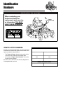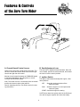
1
FERRIS
OPERATOR’S
MANUAL
ISZ
Zero-Turn Riding Mower
Models:
ISZKAV23/52
ISZKAV23/61
Beginning Serial No:
2269
Ferris Industries
5375 North Main Street
Munnsville, NY 13409
800-933-6175
22422
3/2000
F-ISZ-OWN-00
Table of Contents
Identification Numbers .......................................2
Safety Rules & Information ................................3
Features & Controls ............................................6
Control Functions....................................................6
Safety Interlock System ..........................................7
Operating the Tractor..........................................8
General ...................................................................8
Checks Before Starting ...........................................8
Starting the Engine .................................................9
Stopping the Rider ..................................................9
Mowing....................................................................9
Pushing the Rider by Hand.....................................9
Zero Turn Driving Practice ....................................10
Storage .................................................................12
Starting After Long Term Storage .........................12
Regular Maintenance ........................................14
Maintenance Schedule .........................................14
Checking Tire Pressures.......................................14
Checking/Adding Fuel...........................................15
Fuel Filter ..............................................................15
Oil & Filter Change ...............................................15
Check / Change Air FIlter .....................................15
Check Hydraulic Oil Level.....................................15
Lubrication ............................................................16
Battery Maintenance .............................................17
Checking Battery Fluid..................................17
Cleaning the Battery and Cables..................17
Servicing the Mower Blades .................................18
Troubleshooting, Adjustments & Service .......19
Troubleshooting the Tractor ..................................19
Troubleshooting the Mower ..................................20
Seat Adjustment....................................................21
Ground Speed Control Lever Adjustment .............21
Speed Balancing Adjustment ................................21
Parking Brake Adjustment ....................................22
Suspension Height Adjustment .............................22
PTO Clutch Adjustment.........................................23
Blade Brake Check ...............................................23
Neutral Adjustment................................................24
Dampener and Return Spring Adjustment ............24
Cutting Height Adjustment ....................................25
Hydraulic Pump Drive Belt Replacement .............25
Mower Belt Replacement......................................26
Battery Service......................................................27
Checking the Battery Voltage ...........................27
Charging A Completely
Discharged Battery .......................................27
Jump Starting with
Auxiliary (Booster) Battery ............................27
Lawn Care & Mowing Information.............LC—1
International Symbols ................................LC—8
Technical Manuals ......................................LC—8
NOTE: In this manual, “left” and “right” are referred to as
seen from the operating position.
WARNING
Engine exhaust from this product contains
chemicals known, in certain quantities, to cause
cancer, birth defects, or other reproductive harm.
© Copyright 2000 Ferris Industries
All Rights Reserved. Printed in USA.
F-ISZ-OWN-00
Identification
Numbers
IDENTIFICATION TAG LOCATIONS
When contacting your
Authorized Dealer for
replacement parts, service,
or information YOU MUST
HAVE THESE NUMBERS.
FERRIS
Tractor
identification tag
FERRIS INDUSTRIES, INC.
MUNNSVILLE, NY 13409
MADE IN THE USA
MODEL NO.
SERIAL NO.
XXXXXXX
XXXXXXX
IDENTIFICATION NUMBERS
Record your model name/number, unit and mower deck
manufacturer numbers and engine serial number in the
space provided for easy reference.
•
•
The Tractor I.D. tag is located on the inside of the
main frame rail, behind the deck height plate.
For location of Engine Serial Number, refer to the
Engine Owner’s Manual.
PRODUCT
REFERENCE
DATA
Model Description Name/Number
Unit MFG Number
Unit SERIAL Number
Mower Deck MFG Number
Mower Deck SERIAL Number
N/A
Dealer Name
Be sure to fill out and return the Warranty Registration
Card supplied with your unit.
N/A
Date Purchased
ENGINE REFERENCE DATA
Engine Make/Model
Engine ID/Serial Number
Safety Rules
& Information
Read these safety rules and follow them closely. Failure to obey these rules could result in loss of control of unit, severe personal injury or death to you, or bystanders, or damage to property or equipment.
This mowing deck is capable of amputating hands and feet and throwing objects. The triangle
in text signifies important cautions or warnings which must be followed.
GENERAL OPERATION
• Read, understand, and follow all instructions in the
manual and on the unit before starting.
• Only allow responsible adults, who are familiar with
the instructions, to operate the unit.
• Clear the area of objects such as rocks, toys, wire,
etc., which could be picked up and thrown by the
blade(s).
• Be sure the area is clear of other people before
mowing. Stop unit if anyone enters the area.
• Never carry passengers.
• Do not mow in reverse unless absolutely necessary.
Always look down and behind before and while travelling in reverse.
• Be aware of the mower discharge direction and do
not point it at anyone. Do not operate the mower
without either the entire grass catcher or the deflector in place.
• Slow down before turning.
• Never leave a running unit unattended. Always
disengage the PTO, set parking brake, stop engine,
and remove keys before dismounting.
• Turn off the PTO switch to disengage the blades
when not mowing.
• Stop engine before removing grass catcher or
unclogging chute.
• Mow only in daylight or good artificial light.
• Do not operate the unit while under the influence of
alcohol or drugs.
• Watch for traffic when operating near or crossing
roadways.
• Use extra care when loading or unloading the unit
into a trailer or truck.
• Data indicates that operators, age 60 years and
above, are involved in a large percentage of riding
mower-related injuries. These operators should
evaluate their ability to operate the riding mower
safely enough to protect themselves and others from
serious injury.
SLOPE OPERATION
Slopes are a major factor related to loss-of-control and
tip-over accidents, which can result in severe injury or
death. All slopes require extra caution. If you cannot
back up the slope or if you feel uneasy on it, do not
drive on it.
WARNING
Never operate on slopes greater than 30 percent
(16.7°) which is a rise of three feet vertically in 10
feet horizontally.
Select slow ground speed before driving onto slope.
Use extra caution when operating on slopes with
rear-mounted grass catcher.
Mow UP and DOWN the slope, never across the
face, use caution when changing directions and
DO NOT START OR STOP ON SLOPE.
Do
• Mow up and down slopes, not across.
• Remove obstacles such as rocks, tree limbs, etc.
• Watch for holes, ruts, or bumps. Uneven terrain
could overturn the unit. Tall grass can hide obstacles.
• Use slow speed. Choose a slow speed so that you
will not have to stop or change speed while on the
slope.
• Use extra care with grass catchers or other attachments. These can change the stability of the unit.
• Keep all movement on the slopes slow and gradual.
Do not make sudden changes in speed or direction.
Do Not
• Do not start or stop on a slope. If tires lose traction,
disengage the blade(s) and proceed slowly straight
down the slope.
• Do not turn on slopes unless necessary, and then,
turn slowly and gradually downhill, if possible.
• Do not mow near drop-offs, ditches, or embankments. The mower could suddenly turn over if a
wheel is over the edge of a cliff or ditch, or if an edge
caves in.
• Do not mow on wet grass. Reduced traction could
cause sliding.
• Do not try to stabilize the unit by putting your foot on
the ground.
• Do not use grass catcher on steep slopes.
Safety Rules & Information
CHILDREN
• Never run a unit in an enclosed area.
Tragic accidents can occur if the operator is not alert to
the presence of children. Children are often attracted to
the unit and the mowing activity. Never assume that children will remain where you last saw them.
• Keep nuts and bolts, especially blade attachment
bolts, tight and keep equipment in good condition.
• Never tamper with safety devices. Check their proper
operation regularly.
• Keep children out of the mowing area and under the
watchful care of another responsible adult.
• Keep unit free of grass, leaves, or other debris buildup. Clean up oil or fuel spillage.
• Be alert and turn unit off if children enter the area.
• Stop and inspect the equipment if you strike an
object. Repair, if necessary, before restarting.
• Before and during reverse operation, look behind
and down for small children.
• Never carry children. They may fall off and be seriously injured or interfere with safe unit operation.
• Never allow children to operate the unit.
• Use extra care when approaching blind corners, shrubs,
trees, or other objects that may obscure vision.
TRANSPORTING AND STORAGE
• Always observe safe refueling and fuel handling
practices when refueling the unit after transportation
or storage.
• Always follow the engine manual instructions for
storage preparations before storing the unit for both
short and long term periods.
• Always follow the engine manual instructions for
proper start-up procedures when returning the unit to
service.
• Never store the unit or fuel container inside where
there is an open flame or pilot light, such as in a
water heater. Allow unit to cool before storing.
SERVICE AND MAINTENANCE
• Use extra care when handling gasoline and other
fuels. They are flammable and vapors are explosive.
a) Use only an approved container.
b) Never remove fuel cap or add fuel with the engine
running. Allow engine to cool before refueling. Do
not smoke.
c) Never refuel the unit indoors.
• Never make adjustments or repairs with the engine
running unless specified otherwise in the engine
manufacturer’s manual.
• Grass catcher components are subject to wear, damage, and deterioration, which could expose moving
parts or allow objects to be thrown. Frequently check
components and replace with manufacturer’s recommended parts, when necessary.
• Mower blades are sharp and can cut. Wrap the
blade(s) or wear gloves, and use extra caution when
servicing them.
• Check brake operation frequently. Adjust and service
as required.
• Use only factory authorized replacement parts when
making repairs.
• Always comply with factory specifications on all
settings and adjustments.
• Only authorized service locations should be utilized
for major service and repair requirements.
• Never attempt to make major repairs on this unit
unless you have been properly trained. Improper
service procedures can result in hazardous operation, equipment damage and voiding of manufacturer’s warranty.
Safety Rules & Information
SAFETY DECALS
This unit has been designed and manufactured to provide you with the safety and reliability you would expect
from an industry leader in outdoor power equipment
manufacturing.
Although reading this manual and the safety instructions
it contains will provide you with the necessary basic
knowledge to operate this equipment safely and effectively, we have placed several safety labels on the unit
to remind you of this important information while you are
operating your unit.
All DANGER, WARNING, CAUTION and instructional
messages on your rider and mower should be carefully
read and obeyed. Personal bodily injury can result when
these instructions are not followed. The information is for
your safety and it is important! The safety decals below
are on your rider and mower.
If any of these decals are lost or damaged, replace them
at once. See your local dealer for replacements.
These labels are easily applied and will act as a constant visual reminder to you, and others who may use
the equipment, to follow the safety instructions necessary for safe, effective operation.
OPERATION
To Start Engine:
To Operate PTO Clutch:
Seat must be occupied, PTO
Switch OFF, Parking Brake ON
and both control handles are
locked in Neutral.
Operator must be in seat.
Pull up to Engage.
Push down to Disengage.
When Operator Leaves Seat:
To Stop Engine:
Engage Parking Brake, Throttle at
half to full, turn Ignition Switch Off.
Before Leaving Machine:
Turn PTO switch off, shut off engine,
remove key, and set Parking
Brake
Engine will shut off if PTO is on.
Engine will shut off of Parking Brake
is off.
Engine will shut off if both control
levers are not locked in neutral.
GROUND SPEED AND
STEERING LEVERS
Right lever controls speed
and direction of right drive
wheel. Notch is neutral
lock.
Left lever controls speed and
direction of left drive wheel.
Notch is neutral lock.
Steer by slowing the lever in
the direction of the turn.
PARKING BRAKE
LEVER
Pull to set Parking Brake.
Push to release Parking
Brake.
DECK LIFT PEDAL
Push to raise deck.
CUTTING HEIGHT
ADJUSTMENT PIN
DO NOT TOW!
Damage may result to
Hydrostatic Transmission.
Decal - Warning/Danger
Part No. 45567
Decal - Operation & Controls
Part No. 45559
DANGER
DANGER
ROTATING CUTTING BLADE
Do not put hands or feet
under mower deck while
blade is rotating.
ROTATING CUTTING BLADE
Do not operate mower
without deflector or entire
grass catcher in place.
1704277
1704276
Decal - Danger
Part No. 1704276
WARNING
BEWARE OF
POWER DRIVEN PARTS
Decal - Warning
Part No. 20337
Decal - Danger
Part No. 1704277
DANGER
ROTATING PARTS UNDER ENGINE.
KEEP HANDS AND FEET CLEAR.
STOP ENGINE BEFORE SERVICING.
Decal - Danger
Part No. 22143
Features & Controls
of the Zero Turn Rider
A. Ground Speed Control Levers
B. Seat Adjustment Lever
These levers control the ground speed of the rider. The
left lever controls the left rear drive wheel and the right
controls the right rear drive wheel.
The seat can be adjusted forward and back. Move the
lever forward, position the seat as desired, and release
the lever to lock the seat in position.
Moving a lever forward increases the FORWARD speed
of the associated wheel, and pulling back on a lever
increases the REVERSE speed.
C. Ignition Switch
The ignition switch starts and stops the engine, it has
three positions:
Note: The further a lever is moved away from the neutral
position the faster the drive wheel will turn.
See the Operating the Zero Turn Rider section for steering instructions.
OFF
Stops the engine and shuts off the
electrical system.
RUN
Allows the engine to run and powers the
electrical system.
START Cranks the engine for starting.
NOTE: Never leave the ignition switch in the RUN position with the engine stopped–this drains the battery.
6
Features & Controls
SAFETY
INTERLOCK SYSTEM
D. Parking Brake Handle
The parking brake is applied by pulling UP on the parking brake handle until it locks over-center. To release the
parking brake, push the handle DOWN.
This unit is equipped with safety interlock switches and
other safety devices. These safety systems are present
for your safety, do not attempt to bypass safety switches, and never tamper with safety devices. Check their
operation regularly.
E. PTO (Power Take Off) Switch
The PTO switch engages and disengages the mower.
Pull UP on the switch to engage, and push DOWN to
disengage.
Operational SAFETY Checks
F & G. Deck Lift Pedal & Cutting Height
Adjustment Pin
Your unit is equipped with a seat switch safety system.
Check the seat switch operation every fall and spring
with the following tests.
These control the cutting height of the mower deck.
Test 1 — Engine should NOT crank if:
• PTO switch is engaged, OR
Depress the pedal until it locks into the TRANSPORT
position. Place the adjustment pin in the desired cutting
height and release the lift pedal.
• Parking brake is not engaged, OR
H & I. Throttle / Choke Control
• Motion control handles are not in the NEUTRAL
position, OR
Pulling the round choke control knob (I) out fully chokes
the engine for cold starts. (A warm engine may not
require choking.) Moving the throttle control (H) fully forward is FULL throttle position. Always operate the unit
at FULL throttle when mowing.
• Operator is not on the seat.
Test 2 — Engine SHOULD crank if:
• PTO switch is NOT engaged, AND
• Parking brake is engaged, AND
• Motion control handles are locked in the NEUTRAL
position, AND
J. Hour Meter
Measures the time of the PTO being engaged.
• Operator is on the seat.
K. Fuel Shut Off Valve
Test 3 — Engine should SHUT OFF if:
• Operator rises off seat with PTO engaged, OR
Turning the handle to the desired position determines
which tank will be supplying fuel. With the handle pointing forward, it will draw fuel from the left-hand tank.
With the handle pointed towards the rear, it will draw fuel
from the right-hand fuel tank. With the handle pointing
towards the right, it will shut off fuel flow to the engine.
• Operator rises off seat with parking brake disengaged.
Test 4 — Blade Brake Check
Mower blades and mower drive belt should come to a
complete stop within five seconds after electric PTO
switch is turned off (or operator rises off seat). If mower
drive belt does not stop within five seconds, see your
dealer.
NOTE: Once the engine has stopped, PTO switch must
be turned off, parking brake must be engaged, and the
motion control handles must be locked in the NEUTRAL
position after the operator returns to the seat in order to
start the engine.
WARNING
If the unit does not pass a safety test, do
not operate it. See your authorized dealer. Under
no circumstance should you attempt to defeat
the purpose of the safety interlock system.
7
Operating
the Zero Turn Rider
GENERAL OPERATING SAFETY
WARNING
Before first time operation:
• Be sure to read all information in the Safety and
Operation sections before attempting to operate this
tractor and mower.
Never allow passengers to ride on the unit.
Before leaving the operators position for any
reason, engage the parking brake, disengage the
PTO, stop the engine and remove the key.
• Become familiar with all of the controls and how to
stop the unit.
To reduce fire hazard, keep the engine, tractor
and mower free of grass, leaves and excess
grease. Do not stop or park tractor over dry
leaves, grass or combustible materials.
• Drive in an open area without mowing to become
accustomed to the unit.
Gasoline is highly flammable and must be
handled with care. Never fill the tank when the
engine is still hot from recent operation. Do not
allow open flame, smoking or matches in the
area. Avoid over-filling and wipe up any spills.
CHECKS BEFORE STARTING
• Check that crankcase is filled to full mark on dipstick.
See the engine Operators Manual for instructions
and oil recommendations.
• Make sure all nuts, bolts, screws and pins are in
place and tight.
• Adjust the seat position, and make certain you can
reach all controls from operators position.
• Fill the fuel tanks with fresh fuel. Refer to engine
manual for fuel recommendations.
DANGER
A
OPERATING ON SLOPES
CAN BE DANGEROUS
A
Never operate on slopes greater than 30 percent
(16.7°) which is a rise of three feet vertically in 10
feet horizontally.
Operate the unit at a slow ground speed when
driving onto slope.
B
Use extra caution when operating on slopes with
rear-mounted grass catcher. Mow UP and DOWN
the slope, never across the face, use caution
when changing directions and DO NOT START
OR STOP ON SLOPE.
Figure 2. Pre-start Checks
A. Fuel Tank Filler Neck
B. Crankcase Oil Fill
8
Operating the Zero Turn Rider
WARNING
MOWING
1. Engage the parking brake. Make sure the PTO
switch is disengaged, the motion control handles are
locked in the NEUTRAL position and the operator is
on the seat.
2. Start the engine (see STARTING THE ENGINE).
3. Set the mower cutting height.
4. Set the throttle to FULL.
5. Engage the PTO by pulling up on the PTO switch (E,
Figure 1).
6. Begin mowing. See the LC Section for tips on mowing patterns, lawn care, and trouble shooting information.
7. When finished, shut off the PTO.
8. Stop the engine (see STOPPING THE TRACTOR
AND ENGINE).
If you do not understand how a specific control
functions, or have not yet thoroughly read the
FEATURES & CONTROLS section, do so now.
Do NOT attempt to operate the tractor without
first becoming familiar with the location and
function of ALL controls.
STARTING THE ENGINE
1. While sitting in the operators seat, engage the parking brake and make sure the PTO switch is disengaged and the motion control handles are locked in
the NEUTRAL position.
2. NOTE: A warm engine may not require choking.
Set the engine throttle control (H, Figure 1) to FAST
throttle position. Then fully close the choke (I, Figure
1) by pulling the knob OUT fully.
3. Insert the key into the ignition switch (C, Figure 1)
and turn it to START.
4. After the engine starts, gradually open the choke
(push knob down fully).
Warm up the engine by running it for at least a minute
before engaging the PTO switch or driving the rider.
PUSHING THE RIDER BY HAND
DO NOT TOW RIDER
Towing the unit will cause hydraulic pump
and wheel motor damage. Do not use
another vehicle to push or pull this unit.
5. After warming the engine, ALWAYS operate the
unit at FULL THROTTLE when mowing.
In the event of an emergency the engine can be
stopped by simply turning the ignition switch to
STOP. Use this method only in emergency situations.
For normal engine shut down follow the procedure given
in STOPPING THE RIDER.
1. Disengage the PTO, engage the parking brake, turn
the ignition OFF, and remove the key.
2. Locate the hydraulic by-pass handles under the
machine, behind the fuel tank belly pan. The handles are equipped with a yellow cap on the end for
easy identification.
3. To disengage the pumps (free-wheel position), move
the hydraulic by-pass handles towards the left-hand
side of the machine, approximately 90 degrees from
its original position.
STOPPING THE RIDER
1. Returning the ground speed control levers (A, Figure
1) to the middle position will stop tractor movement.
Pivot the levers outward and lock them in NEUTRAL.
2. Disengage the PTO by pushing down on the PTO
switch (E, Figure 1).
3. Engage the parking brake by pulling the handle (D,
Figure 1) up until it locks into position.
4. Move the throttle control (H, Figure 1) to mid-throttle
position and turn the ignition key to OFF. Remove
the key.
4. Disengage the parking brake. The tractor can now
be pushed by hand.
5. After moving the tractor, re-engage the pumps (drive
position) by moving the hydraulic by-pass handles
towards the right-hand side of the machine until they
stop.
9
Operating the Zero Turn Rider
ZERO TURN
DRIVING PRACTICE
Smooth Travel
The lever controls of the
Zero Turn rider are
RESPONSIVE .
The lever controls of the Zero Turn rider are responsive,
and learning to gain a smooth and efficient control of the
rider’s forward, reverse, and turning movements will take
some practice.
The BEST method of
handling the ground
speed control levers is in
three steps — as shown
in Figure 3.
Spending some time going through the maneuvers
shown and becoming familiar with how the unit accelerates, travels, and steers — before you begin mowing —
is absolutely essential to getting the most out of the Zero
Turn rider.
FIRST place your hands
onto the levers as shown.
Locate a smooth, flat area of your lawn — one with
plenty of room to maneuver. (Clear the area of
objects, people and animals before you begin.) Operate
the unit at mid-throttle during this practice session
(ALWAYS operate at full throttle when mowing), and turn
slowly to prevent tire slippage and damage to your lawn.
SECOND, to go forward
gradually push the levers
forward with your palms.
We suggest you begin with the Smooth Travel procedure to the right, and then advance through the forward,
reverse, and turning maneuvers.
THIRD, to speed up
move the levers farther
forward. To slow down
smoothly, slowly move
the levers toward neutral.
You must release the parking brake prior to moving the
control levers inward.
Figure 3. Move Control
Levers Gradually
BASIC DRIVING
Forward Travel Practice
Reverse Travel Practice
Gradually move both ground speed control levers —
evenly FORWARD from neutral. Slow down and repeat.
LOOK DOWN & BEHIND, then gradually move both
ground speed control levers evenly BACK from neutral.
Slow down and repeat.
NOTE: Straight forward travel takes practice. If necessary, top speed can be balance-adjusted — see the
Speed Balancing Adjustment in the Adjustments section
near the back of this manual.
NOTE: Practice backing up for several minutes before
attempting to do so near objects. The rider turns sharply
in reverse as well as forward, and backing up straight
takes practice.
Reverse
Travel
Forward
Travel
Figure 4. Forward Travel
Figure 5. Forward Travel
10
Operating the Zero Turn Rider
Practice Turning Around a Corner
Practice Turning In Place
While traveling forward allow one handle to gradually
return back toward neutral. Repeat several times.
To turn in place, “Zero Turn,” gradually move one ground
speed control lever forward from neutral and one lever
back from neutral simultaneously. Repeat several times.
NOTE: To prevent pivoting directly on the tire tread, it is
best to keep both wheels going at least slightly forward.
NOTE: Changing the amount each lever is pulled—forward or back, changes the “pivot point” you turn on.
Turning
In-Place
Executing
Turns
Figure 6. Turning Around a Corner
Figure 7. Turning in Place
ADVANCED DRIVING
Executing an End-Of-Row Zero
Turn
Your Zero Turn Rider’s unique ability to turn
in place allows you to turn around at the end
of a cutting row rather than having to stop
and Y-turn before starting a new row.
For example, to execute a right end-of row
Zero Turn:
1. Slow down at the end of the row.
2. Move the LEFT ground speed control
lever forward slightly while moving the
RIGHT ground speed control lever back
to center and then slightly back from center.
3. Begin mowing forward again.
This technique turns the rider RIGHT and
slightly overlaps the row just cut —eliminating
the need to back up and re-cut missed grass.
As you become more familiar and experienced with operating the Zero Turn rider, you
will learn more maneuvers that will make
your mowing time easier and more enjoyable.
Remember, the more you practice, the better
your control of the Zero Turn will be!
11
Operating the Zero Turn Rider
STORAGE
WARNING
Temporary Storage (30 Days Or Less)
Never store the unit, with gasoline in engine or
fuel tank, in a heated shelter or in enclosed,
poorly ventilated enclosures. Gasoline fumes may
reach an open flame, spark or pilot light (such as
a furnace, water heater, clothes dryer, etc.) and
cause an explosion.
Remember, the fuel tank will still contain some gasoline, so
never store the unit indoors or in any other area where fuel
vapor could travel to any ignition source. Fuel vapor is also
toxic if inhaled, so never store the unit in any structure
used for human or animal habitation.
Here is a checklist of things to do when storing your unit
temporarily or in between uses:
Handle gasoline carefully. It is highly flammable
and careless use could result in serious fire
damage to your person or property.
• Keep the unit in an area away from where children may
come into contact with it. If there’s any chance of unauthorized use, remove the spark plug (s) and put in a
safe place. Be sure the spark plug opening is protected
from foreign objects with a suitable cover.
Drain fuel into an approved container outdoors
away from open flame or sparks.
• If the unit can’t be stored on a reasonable level surface,
chock the wheels.
10. Drain fuel system completely or add a gasoline stabilizer to the fuel system. If you have chosen to use a fuel
stabilizer and have not drained the fuel system, follow
all safety instructions and storage precautions in this
manual to prevent the possibility of fire from the ignition
of gasoline fumes. Remember, gasoline fumes can travel to distant sources of ignition and ignite, causing risk
of explosion and fire.
• Clean all grass and dirt from the mower.
Long Term Storage (Longer Than 30 Days)
Before you store your unit for the off-season, read the
Maintenance and Storage instructions in the Safety Rules
section, then perform the following steps:
1. Drain crankcase oil while engine is hot and refill with a
grade of oil that will be required when unit is used
again.
NOTE: Gasoline, if permitted to stand unused for extended
periods (30 days or more), may develop gummy deposits
which can adversely affect the engine carburetor and cause
engine malfunction. To avoid this condition, add a gasoline
stabilizer to the fuel tank and run the engine a few minutes,
or drain all fuel from the unit before placing it in storage.
2. Prepare the mower deck for storage as follows:
a. Remove mower deck from the unit.
b. Clean underside of mower deck.
c. Coat all bare metal surfaces with paint or light coat of
oil to prevent rusting.
3. Clean external surfaces and engine.
STARTING AFTER
LONG TERM STORAGE
4. Prepare engine for storage. See engine owner’s
manual.
Before starting the unit after it has been stored for a long
period of time, perform the following steps.
5. Clean any dirt or grass from cylinder head cooling fins,
engine housing and air cleaner element.
1. Remove any blocks from under the unit.
6. Cover air cleaner and exhaust outlet tightly with plastic
or other waterproof material to keep out moisture, dirt
and insects.
3. Unplug the exhaust outlet and air cleaner.
2. Install the battery if it was removed.
4. Fill the fuel tank with fresh gasoline. See engine
manual for recommendations.
7. Completely grease and oil unit as outlined in the
Normal Care section.
5. See engine owner’s manual and follow all instructions
for preparing engine after storage.
8. Clean up unit and apply paint or rust preventative to
any areas where paint is chipped or damaged.
6. Check crankcase oil level and add proper oil if
necessary. If any condensation has developed during
storage, drain crankcase oil and refill.
9. Be sure the battery is filled to the proper level with
water and is fully charged. Battery life will be increased
if it is removed, put in a cool, dry place and fully
charged about once a month. If battery is left in unit,
disconnect the negative cable.
7. Inflate tires to proper pressure. Check fluid levels.
8. Start the engine and let it run slowly. DO NOT run at
high speed immediately after starting. Be sure to run
engine only outdoors or in well ventilated area.
12
Notes
13
Regular
Maintenance
MAINTENANCE SCHEDULE & PROCEDURES
The following schedule should be followed for normal care of your rider and mower. You will need to keep a record
of your operating time. Determining operating time is easily accomplished by observing the hour meter.
See
Page
Before
First Use
Check Safety Interlock System
7
X
X
Check Rider Brakes
22
X
X
23
See
Page
X
Before
First Use
SAFETY ITEMS
Check Mower Blade Stopping Time
NORMAL CARE ITEMS
Before
Each Use
Every
5 Hours
Before
Each Use
Every
5 Hours
X
X
X
X
Every
25 Hours
Every
25 Hours
Every
100 Hours
X
Every
100 Hours
Check Rider/Mower for loose hardware
—
Check Engine Oil Level
15*
Check Engine Air Filter
15*
Change Engine Oil & Filter **
15*
Lubricate Rider & Mower
16
Check Tire Pressure
14
X
***X
Check Hydraulic Fluid
15
X
***X
Check Fuel Filter
15
X
Clean Battery & Cables
17
X
Clean & Sharpen Mower Blades
18
X
Inspect Spark Plug
15*
X
X
X
***X
***X Every 50 Hours
***X
CHECK TIRE PRESSURES
Tire Pressure should be checked periodically, and maintained at the levels shown in the chart. Note that these
pressures may differ slightly from the “Max Inflation”
stamped on the side-wall of the tires. The pressures
shown provide proper traction, improve cut quality, and
extend tire life.
Pressure
Front
20 psi (138 kPa)
Rear
15 psi (103 kPa)
Figure 9. Checking Tire Pressure
14
Spring
& Fall
X
* See the engine manufacturer's owner's manual.
** Change original engine oil after first 5 hours of operation.
*** More often in hot (over 85° F: 30° C) weather or dusty operating conditions.
Tire
Spring
& Fall
***X
Regular Maintenance
CHECKING / ADDING FUEL
WARNING
To add fuel:
1. Remove the fuel cap (see A, Figure 2).
2. Fill the tank.
Do not overfill. Leave approximately 1” of room in the
tank for fuel expansion. Refer to your engine manual for specific fuel recommendations.
3. Install and hand tighten the fuel cap.
Gasoline is highly flammable and must be
handled with care. Never fill the tank when the
engine is still hot from recent operation. Do not
allow open flame, smoking or matches in the
area. Avoid over-filling and wipe up any spills.
Do not remove fuel filter when engine is hot, as
spilled gasoline may ignite. DO NOT spread hose
clamps further than necessary. Ensure clamps
grip hoses firmly over filter after installation.
4. Repeat same process for opposite tank.
FUEL FILTER
The fuel filter is located in the fuel line between fuel shut
off valve and carburetor, near the fuel pump. If filter is
dirty or clogged, replace as follows:
1. Shut off the fuel valve.
2. Disconnect the negative battery cable.
3. Place a container below the filter to catch spilled
fuel.
4. Using a pliers, open and slide hose clamps from fuel
filter.
5. Remove hoses from filter.
6. Install new filter in proper flow direction in fuel line.
Do not use gasoline containing METHANOL,
gasohol containing more than 10% ethanol,
gasoline additives, premium gasoline, or
white gas because engine/fuel system
damage could result.
7. Secure with hose clamps.
8. Reconnect the negative battery cable when finished.
OIL & FILTER CHANGE
Refer to engine owners manual.
B
CHECK / CHANGE AIR FILTER
A
Refer to engine owners manual.
REPLACE SPARK PLUG
Figure 10. Checking Hydraulic Oil Level
A. Hydraulic Oil Reservoir (Right-side shown)
B. Breather
Refer to engine owners manual.
CHECK HYDRAULIC OIL LEVEL
NOTE: Do not open the hydraulic oil reservoir unless oil
is being added.
1. Remove the breather (B, Figure 10) from the filler
neck of the hydraulic oil reservoir (A, Figure 10).
2. With a small diameter steel dowel, use it as a dipstick to check the oil level. When cold, there should
be 3” of oil on the dowel.
3. If necessary, add either Mobil 1, 15W-50 synthetic oil
or Castrol Syntec 5W-50 oil. DO NOT use conventional oils. Make sure area around the filler neck is
free of dust, dirt, or other debris.
15
Regular Maintenance
LUBRICATION
Lubricate the unit at the locations shown in Figures 11
through 13 as well as the following lubrication points.
Grease:
•
•
•
•
•
•
•
•
front caster wheel axles
motion control pivots
suspension a-arms
rear deck mounts
deck lift pivots
deck lift foot pedal
front pivot frame
blade spindles
Figure 11. Suspension Lubrication
Top & Bottom, Left & Right
Use grease fittings when present. Disassemble parts
to apply grease to moving parts when grease fittings
are not installed.
Not all greases are compatible. Ferris Red Grease is
recommended, automotive-type high-temperature,
lithium grease may be used when this is not available.
Oil:
• control handle pivots
• floor plate hinge
• discharge chute hinge
Generally, all moving metal parts should be oiled
where contact is made with other parts. Keep oil
and grease off belts and pulleys. Remember to wipe
fittings and surfaces clean both before and after
lubrication.
Figure 12. Rear Control Pivot Lubrication
Figure 13. Lift Pivot Lubrication
16
Regular Maintenance
BATTERY MAINTENANCE
WARNING
Checking the Battery Fluid
Be careful when handling the battery. Avoid
spilling electrolyte. Keep flames and sparks away
from the battery.
1. Raise the seat plate to access battery.
2. Remove the rubber strap and battery box cover.
3. Remove the battery filler cap (A, Figure 14). Fluid
must be even with the split ring full mark. If not, add
distilled water.
When removing or installing battery cables,
disconnect the negative cable FIRST and reconnect
it LAST. If not done in this order, the positive
terminal can be shorted to the frame by a tool.
4. Reinstall the filler cap.
5. Reinstall the the battery box cover and rubber strap.
Cleaning the Battery and Cables
B
1. Disconnect the cables from the battery, negative
cable first (C, Figure 14).
2. Remove the battery and clean the compartment with
a solution of baking soda and water.
3. Clean the battery terminals and cable ends with a
wire brush until shiny.
A
4. Reinstall the battery and reattach the battery cables,
positive cable first (see B, Figure 14)
C
5. Coat the cable ends and battery terminals with petroleum jelly or non-conducting grease.
Figure 14. Battery Compartment
A. Vent Cap(s)
B. Positive (+) Cable & Terminal
C. Negative (-) Cable & Terminal
17
Regular Maintenance
SERVICING THE MOWER BLADES
1. Blades should be sharp and free of nicks and dents.
If not, sharpen blades as described in following
steps.
2. To remove blade for sharpening, use a wood block to
hold blade while removing the blade mounting bolt
(Figure 15).
3. Use a file to sharpen blade to fine edge. Remove all
nicks and dents in blade edge. If blade is severely
damaged, it should be replaced.
4. Balance the blade as shown in Figure 16. Center the
blade’s hole on a nail lubricated with a drop of oil. A
balanced blade will remain level.
LOOSEN
5. Reinstall each blade with the tabs pointing up toward
deck as shown in Figure 17. The five (5) blade spacers, blade, washer and bolt must be reinstalled in the
exact same order in which they were removed.
Secure with a bolt and hex nut. Use a wooden block
to prevent blade rotation and torque bolts to 70 ft.lbs.
(94 N.m.).
Figure 15. Removing the Blade
Nail
WARNING
For your personal safety, blade mounting bolts
must each be installed with a flat washer then
securely tightened. Torque blade mounting bolts
to 70 ft.lbs. (94 N.m.)
Figure 16. Balancing The Blade
B
A
TIGHTEN
Figure 17. Installing The Blade
A. 4x4 Wood Block
B. Flat Washer
18
C. Blade Bolt
Troubleshooting, Adjustment & Service
Rider Troubleshooting Continued.
PROBLEM
CAUSE
REMEDY
Engine runs, but rider will
not drive.
1. Hydraulic release valve(s)
in “open” position.
2. Belt is broken.
3. Drive belt slips.
4. Brake is not fully released.
1. Clutch is out of adjustment.
2. Pulleys or belt greasy or oily.
3. Belt stretched or worn.
1. Brake is incorrectly adjusted.
2. Brake caliper pads worn.
1. Steering linkage is loose.
2. Improper tire inflation.
1. Turn valve(s) clockwise to close.
Rider drive belt slips.
Brake will not hold.
Rider steers or handles poorly.
2.
3.
4.
1.
2.
3.
1.
2.
1.
2.
See Drive Belt Replacement.
See problem and cause below.
See authorized service dealer
See authorized service dealer.
Clean as required.
Replace belt.
See Brake Adjustment.
Replace with new brake pads.
Check and tighten any loose connections.
See Regular Maintenance Section.
TROUBLESHOOTING THE MOWER
PROBLEM
CAUSE
REMEDY
Mower will not raise.
1. Lift linkage not properly attached
or damaged.
1. Mower not leveled properly.
2. Rider tires not inflated
equally or properly.
1. Engine speed too slow.
2. Ground speed too fast.
3. Blades are dull.
1. See authorized service dealer for repair.
Mower cut is uneven.
Mower cut is rough looking.
Engine stalls easily with
mower engaged.
Excessive mower vibration.
Excessive belt wear or breakage.
Mower drive belt slips
or fails to drive.
4. Mower drive belt slipping
because it is oily or worn.
5. Blades not properly fastened
to arbors.
1. Engine speed too slow.
2. Ground speed too fast.
3. Cutting height set too low.
4. Discharge chute jamming
with cut grass.
1. Blade mounting screws
are loose.
2. Mower blades, arbors,
or pulleys are bent.
3. Mower blades are out
of balance.
4. Belt installed incorrectly.
1. Bent or rough pulleys.
2. Using incorrect belt.
1. Idler pulley spring broken or not
properly attached.
2. Mower drive belt broken.
20
1. See Mower Adjustment.
2. See Regular Maintenance Section.
1. Set throttle to full.
2. Decrease Ground Speed.
3. Sharpen or replace blades.
See Mower Blade Service.
4. Clean or replace belt as necessary.
5. See Servicing the Mower Blades.
1. Set to full throttle.
2. Decrease Ground Speed.
3. Cut tall grass at maximum cutting
height during first pass.
4. Cut grass with discharge pointing toward
previously cut area.
1. Tighten to 45-55 ft.lbs. (61-75 N.m.).
2. Check and replace as necessary.
3. Remove, sharpen, and balance blades.
See Maintenance Section.
4. Reinstall Correctly.
1. Repair or replace.
2. Replace with correct belt.
1. Repair or replace as needed.
2. Replace drive belt.
Troubleshooting, Adjustment & Service
SEAT ADJUSTMENT
Seat Adjustment Lever
See Figure 18. The seat can be adjusted forward and
back. Move the lever forward, position the seat as
desired, and release the lever to lock the seat into position.
GROUND SPEED CONTROL LEVER
ADJUSTMENT
Figure 18. Seat Adjustment
The control levers can be adjusted in two ways. The
alignment of the control levers can be adjusted along
with the placement of the levers (how close the ends are
to one another) can be adjusted.
A
To Adjust the Handle Alignment
Loosen the mount bolts (A, Figure 19) and pivot the
lever(s) (C, Figure 19) to align with each other.
C
B
To Adjust the Handle Placement
Loosen the jam nuts and adjust the placement bolt (B,
Figure 19) in or out to properly adjust the lever end
spacing.
SPEED BALANCING ADJUSTMENT
Figure 19. Control Lever Adjustment
A. Alignment Hardware
B. Placement Hardware
C. Ground Speed Control Lever
If the rider veers to the right or left when the ground
speed control levers are in the maximum forward position, the top speed of each of these levers can be balanced by turning the adjustment bolt(s) (A, Figure 20).
Only adjust the speed of the wheel that is traveling
faster.
FRONT
To Reduce the Speed of the Faster Wheel
1. Loosen the lock nut.
2. turn the top speed adjustment bolt COUNTERCLOCKWISE to reduce the speed.
3. Retighten the lock nut when adjustment is complete.
WARNING
C
DO NOT adjust the tractor for a faster overall
speed forward or reverse than it was designed
for.
B
A
Figure 20. Top Speed Adjustment
(Right side shown with control cover removed.)
A. Top Speed Adjustment Bolt
B. Control Lever Base
C. Neutral Lock Plate
21
Troubleshooting, Adjustment & Service
PARKING BRAKE ADJUSTMENT
FRONT
1. Disengage the PTO, stop the engine, block the front
wheels, remove the ignition key, and engage the
parking brake.
A
2. Remove both control covers.
3. Locate the upper brake spring (A, Figure 21).
4. With the parking brake engaged, measure the compressed spring length. The spring should be 2” to 21/8” (5.0 - 5.4cm) when compressed.
5. If the spring is not within this range, jack up the rear
of the machine and secure with jackstands. Remove
both drive tires.
Figure 21. Parking Brake Adjustment
A. Upper Brake Spring
6. Locate the lower brake spring (A, Figure 22), adjustment nuts (B, Figure 22) and adjustment link (C,
Figure 22).
A
7. Release the parking brake and turn the adjustment
nuts to compress or release the upper spring. Lock
the nuts against the adjustment link (C, Figure 22).
B
NOTE: Do not adjust the spring to be shorter than 2”
when compressed. This may damage the caliper case.
If this problem does not correct a braking problem,
see your dealer.
C
SUSPENSION HEIGHT ADJUSTMENT
Figure 22. Parking Brake Adjustment
A. Lower Brake Spring
B. Adjustment Nuts
C. Adjustment Link
If the rider tilts either side-to-side or front-to-rear, this
adjustment will level the frame with the ground.
Although this adjustment may not be necessary, it may
be required if additional weight (ie. a grass catcher) is
added to the frame or a drive tire is replaced.
A
To level the frame, loosen the jam nut (B, Figure 23) and
turn turn the height adjustment bolt (A, Figure 23)
COUNTER-CLOCKWISE to lower the corresponding
side of the frame, and CLOCKWISE to raise the frame.
B
NOTE: Perform this adjustment on a hard, level surface
such as a concrete floor. Making this adjustment will
affect the mower cutting height. For fine cutting height
adjustment, see your authorized dealer.
Figure 23. Suspension Height Adjustment
A. Height Adjustment Bolt
B. Jam Nut
22
Troubleshooting, Adjustment & Service
WARNING
PTO CLUTCH ADJUSTMENT
Check the PTO clutch adjustment after the initial 50
hour break-in period and then after every 250 hours of
operation. Also perform the following procedure if the
clutch is slipping or will not engage, or if a new clutch
has been installed.
To avoid serious injury, perform adjustments only
with engine stopped, key removed and tractor on
level ground.
Blade Brake Check
1. Remove key from ignition switch and disconnect
spark plug wires to prevent the possibility of accidental starting while the PTO is being adjusted.
Mower blades and mower drive belt should come to a
complete stop within five seconds after electric PTO
switch is turned off.
2. See Figure 24. Note the position of the 3 adjustment
windows (A) in the side of the brake plate and the
nylock adjustment nuts (B).
1. With parking brake engaged, PTO disengaged and
an operator in the seat, start the engine engine.
3. Insert a .010”-.015” (2.5-4mm) feeler gauge (C)
through each window, positioning the gauge between
the rotor face and the armature face as shown in
Figure 25.
2. Look down through the gap between the left side of
the floor and frame rail and observe the POT drive
belt. Engage the PTO and wait several seconds.
Disengage the PTO and check the amount of time it
takes for the mower drive belt to stop.
4. Alternately tighten the adjustment nuts (B, Figure 24)
until the rotor face and armature face just contacts
the gauge.
3. If the mower drive belt does not stop within five seconds, perform the PTO Clutch Adjustment. If the belt
still does not stop within 5 seconds, see your dealer.
5. Check the windows for an equal amount of tension
when the gauge is inserted and removed, and make
any necessary adjustments by tightening or loosening the adjustment nuts.
NOTE: The actual air gap between the rotor and armature may vary even after performing the adjustment procedure. This is due to dimensional variations on component parts, and is an acceptable condition.
6. Check the mower blade stopping time. The mower
blades and mower drive belt should come to a complete stop within five seconds after the electric PTO
switch is turned off.
23
Troubleshooting, Adjustment & Service
NEUTRAL ADJUSTMENT
If the tractor “creeps” while the ground speed control
levers are locked in NEUTRAL, than it may be necessary to adjust the control linkage.
A
B
NOTE: Perform this adjustment on a hard, level surface
such as a concrete floor.
1. Disengage the PTO, engage the parking brake and
turn off the engine.
2. Loosen the jam nut (B, Figure 26) and turn the
adjustment linkage (A, Figure 26) to adjust. If the
machine creeps forward, turn the linkage CLOCKWISE (while standing at the rear of the machine, facing forward), if the machine creeps backward, turn
the linkage COUNTER-CLOCKWISE.
3. Lock the jam nut (B) when neutral is achieved.
NOTE: This adjustment should not be performed while
the machine is running. It may take several attempts to
achieved neutral, depending upon how much the
machine creeps.
DAMPENER FORCE & NEUTRAL
SPRING RETURN ADJUSTMENT
These adjustments will taylor the “feel” of the control
levers to the operator.
Each of the dampeners and springs (C and A, Figure
27) has three adjustment holes (D and B, Figure 27).
The farther up the dampener and spring is placed, the
more effective the dampener becomes and the more
spring force will be felt by the operator while driving forward.
The closer together the dampeners and springs are
placed, the slower the machine will return to NEUTRAL
when the control levers are released. The farther apart
the dampeners and springs are placed, the faster the
machine will return to neutral.
NOTE: These adjustments must be made to BOTH
sides at the same time, and be placed in the SAME
position to one another.
Figure 26. Neutral Adjustment
A. Control Linkage
B. Jam Nut
Troubleshooting, Adjustment & Service
CUTTING HEIGHT ADJUSTMENT
B
WARNING
Before checking mower, shut off PTO and engine.
Allow all moving parts to stop. Remove ignition
key, then disconnect the spark plug wire and
fasten it away from the spark plug.
C
The cutting height adjustment pin (A, Figure 28) controls
the mower cutting height. The cutting height is
adjustable between 1-3/4” (4.4cm) and 5” (12.7cm) in
1/4” (.64cm) increments.
A
Depress the deck lift foot pedal (B, Figure 28), placing
the majority of the force on the top edge of the pedal
until it locks into the “TRANSPORT” position. Place the
cutting height adjustment pin in the desired cutting
height. Depress the deck lift foot pedal, placing the
majority of the force on the bottom edge of the pedal to
release the pedal from the “TRANSPORT” position.
Figure 28. Cutting Height Adjustment
A. Cutting Height Adjustment Pin
B. Deck Lift Foot Pedal
C. Cutting Height Selection Decal
HYDRAULIC PUMP DRIVE BELT
REPLACEMENT
FRONT
1. Park the tractor on a smooth, level surface such as a
concrete floor. Disengage the PTO, engage the
parking brake, turn off the engine, and remove the
ignition key.
E
H
F
F
D
E
G
2. Remove the PTO drive belt (see MOWER BELT
REPLACEMENT for removal instructions).
A
3. Remove the nuts fastening the spring anchor bolts
(H, Figure 29) to the anchor arm.
C
4. Remove the old belt and replace it with the new one.
Be sure the ribs of the belt are seated correctly in
the grooves of the pump pulleys, crankshaft pulley
and the ribbed idler pulleys (C, B and E, Figure 29).
C
B
Figure 29. Hydraulic Pump Drive Belt Replacement
A. Pump Drive Belt
E. Idler Pulley (Ribbed)
B. Crankshaft Pulley
F. Idler Pulley (Smooth)
C. Pump Pulley
G. Idler Arm
D. Spring(s)
H. Spring Anchor Bolt(s)
5. Reinstall the anchor bolts (H, Figure 29) into the
anchor arm and fasten the nuts.
6. Reinstall the PTO drive belt.
25
Troubleshooting, Adjustment & Service
MOWER BELT REPLACEMENT
B
A
To avoid damaging belts, DO NOT
PRY BELTS OVER PULLEYS.
1. Park the tractor on a smooth, level surface such as a
concrete floor. Disengage the PTO, engage the
parking brake, turn off the engine, and remove the
ignition key.
2. Remove the hairpin clip and clevis pin and remove
the deck lift foot pedal. Lift the floor plate to gain
access to the PTO drive belt.
Figure 30. Mower PTO Belt
A. Belt Tension Spring
B. Spring Compression Nut
3. Loosen the spring compression nut (B, Figure 30) to
release the belt tension.
4. Slide the drive belt over the edge of the idler pulley.
Drop the belt from the PTO clutch pulley groove.
D
B
5. Remove the old belt and replace with a new one.
Make sure the V-side of the belt runs in the pulley
grooves (Figure 31).
6. Install the drive belt on the PTO pulley, the spindle
pulleys and idler pulleys. Tighten the spring compression nut (B, Figure 30) until the belt tension
spring (A, Figure 30) is 5/8” long.
7. Run the mower under no-load condition for about 5
minutes.
C
A
A
D
D
A
Figure 31. Mower PTO Belt Routing
A. Spindle Pulley
C. Spring-loaded Idler Pulley
B. PTO Drive Belt
D. Stationary Idler Pulley
26
Troubleshooting, Adjustment & Service
BATTERY SERVICE
6. Charge the battery until fully charged (until the specific gravity of the electrolyte is 1.250 or higher and
the electrolyte temperature is at least 60° F). The
best method of making certain a battery is fully
charged, but not over charged, is to measure the
specific gravity of a cell once per hour. The battery is
fully charged when the cells are gassing freely at low
charging rate and less than 0.003 change in specific
gravity occurs over a three hour period.
WARNING
Keep open flames and sparks away from the
battery; the gasses coming from it are highly
explosive. Ventilate the battery well during
charging.
Checking Battery Voltage
JUMP STARTING WITH AUXILIARY
(BOOSTER) BATTERY
A voltmeter can be used to determine condition of battery. When engine is off, the voltmeter shows battery
voltage, which should be 12 volts. When engine is running, the voltmeter shows voltage of charging circuit
which normally is 13 to 14 volts.
Jump starting is not recommended. However, if it must
be done, follow these directions. Both booster and discharged batteries should be treated carefully when using
jumper cables. Follow the steps below EXACTLY, being
careful not to cause sparks. Refer to Figure 43 .
A dead battery or one too weak to start the engine may
not mean the battery needs to be replaced. For example, it may mean that the alternator is not charging the
battery properly. If there is any doubt about the cause of
the problem, see your dealer. If you need to replace the
battery, follow the steps under Cleaning the Battery &
Cables in the Regular Maintenance Section.
1. Both batteries must be of the same voltage.
2. Position the vehicle with the booster battery adjacent
to the vehicle with the discharged battery so that
booster cables can be connected easily to the batteries in both vehicles. Make certain vehicles do not
touch each other.
CHARGING A COMPLETELY
DISCHARGED BATTERY
3. Wear safety glasses and shield eyes and face from
batteries at all times. Be sure vent caps are tight.
Place damp cloth over vent caps on both batteries.
1. Be aware of all the safety precautions you should
observe during the charging operation. If you are
unfamiliar with the use of a battery charger and
hydrometer, have the battery serviced by your dealer.
2. Add distilled water sufficient to cover the plate (fill to
the proper level near the end of the charge). If the
battery is extremely cold, allow it to warm before
adding water because the water level will rise as it
warms. Also, an extremely cold battery will not
accept a normal charge until it becomes warm.
4. Connect positive (+) cable to positive post of discharged battery (wired to starter or solenoid).
5. Connect the other end of same cable to same post
marked positive (+) on booster battery.
6. Connect the second cable negative (-) to other post
of booster battery.
7. Make final connection on engine block of stalled
vehicle away from battery. Do not lean over batteries.
8. Start the engine of the vehicle with the booster battery. Wait a few minutes, then attempt to start the
engine of the vehicle with the discharged battery.
3. Always unplug or turn the charger off before attaching or removing the clamp connections.
9. If the vehicle does not start after cranking for thirty
seconds, STOP PROCEDURE. More than thirty seconds seldom starts the engine unless some mechanical adjustment is made.
4. Carefully attach the clamps to the battery in proper
polarity (usually red to [+] positive and black to [-]
negative).
5. While charging, periodically measure the temperature of the electrolyte. If the temperature exceeds
125° F (51.6° C), or if violent gassing or spewing of
electrolyte occurs, the charging rate must be
10. After starting, allow the engine to return to idle
speed. Remove the cable connection at the engine
or frame. Then remove the other end of the same
cable from the booster battery.
11. Remove the other cable by disconnecting at the discharged battery first and then disconnect the opposite end from the booster battery.
12. Discard the damp cloths that were placed over the
battery vent caps.
27
Troubleshooting, Adjustment & Service
THIS HOOK-UP FOR NEGATIVE GROUND VEHICLES
To
Starter
Switch
To
Starter
Switch
Jumper Cable
Starting
Vehicle
Battery
Discharged
Vehicle
Battery
Jumper Cable
To Ground
Engine
Block
MAKE CERTAIN VEHICLES DO NOT TOUCH
Figure 32. Jump Starting
WARNING
WARNING
Any procedure other than the preceding could
result in:
(1) personal injury caused by electrolyte
squirting out the battery vents,
(2) personal injury or property damage due to
battery explosion,
(3) damage to the charging system of the
booster vehicle or of the immobilized
vehicle.
Do not attempt to jump start a vehicle having a
frozen battery because the battery may rupture or
explode. If a frozen battery is suspected, examine
all fill vents on the battery. If ice can be seen or if
the electrolyte fluid cannot be seen, do not
attempt to start with jumper cables as long as the
battery remains frozen.
For your personal safety, use extreme care when
jump starting. Never expose battery to open flame
or electric spark – battery action generates
hydrogen gas which is flammable and explosive.
Do not allow battery acid to contact skin, eyes,
fabrics, or painted surfaces. Batteries contain a
sulfuric acid solution which can cause serious
personal injury or property damage.
When removing or installing battery cables, disconnect the negative cable FIRST and reconnect
it LAST. If not done in this order, the positive terminal can be shorted to the frame by a tool.
To avoid engine damage, do not disconnect battery while engine is running. Be sure terminal
connections are tight before starting.
28
Notes
29