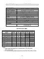
1
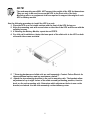
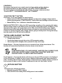
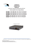
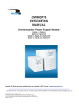
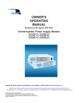
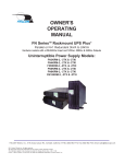
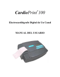
OWNER'S
OPERATING
MANUAL
XG Series Mini-Tower or Rackmount UPS Plus®
Uninterruptible Power Supply Models
XG1.5K-1T,
XG2.2K-1T & XG3K-1T
Shown in mini-tower position with base brackets installed.
FALCON® Electric Inc., 5116 Azusa Canyon Rd., Irwindale, California 91706, (626) 962-7770, Fax 626-962-7720, Email: [email protected]
2005 Falcon® Electric Inc. All rights reserved.
All other brand names and trademarks are the property of their respective owners.
The information stated in this document is subject to change without notice. 2005-10-14
Falcon®, Falcon® Electric and UPS Plus logos are registered trademarks of Falcon Electric Inc
OM48030 Rev.
TABLE OF CONTENTS
SAFETY INFORMATION………………………….. 3
1.0 INTRODUCTION…………………………………….4
2.0 CIRCUIT DESCRIPTIONS…………………. 5
Input Filter
Current and Power Factor Regulator
DC/AC Inverter
Charger
DC/DC Converter
Battery
Bypass Switch
Output Filter
3.0 INSTALLATION…………………………………… 6
Unpacking
Inspecting the Equipment
Rack-Mount UPS Setup
Free-Standing UPS Installation
Battery Module Installation
4.0 DISPLAY AND CONTROLS……………………. 12
Indicators and LCD Display
Controls
5.0 OPERATION……………………………………… 15
Operating Modes
Turning UPS On
Turning UPS Off
6.0 CONFIGURATION………………………………. 17
Green Mode Setting
Voltage Setting
7.0 COMMUNICATION……………………………… 19
RS-232 Port
Dry Contact Option Boards
8.0 MAINTENANCE…………………………………. 22
UPS and Battery Care
Storing the UPS and Batteries
When to Replace Batteries
Battery Pack Replacement
Testing New Batteries
Recycling the Used Battery
Fuse Replacement
9.0 TROUBLESHOOTING…………………………..26
Audible Alarms and UPS Conditions
Troubleshooting Guide
SPECIFICATIONS………………………………. 28
BATTERY RUN TIMES…………………………... 30
WARRANTY…………………………………………31
2
IMPORTANT SAFETY INSTRUCTIONS
SAVE THESE INSTRUCTIONS
RETAIN THIS USER MANUAL
This manual contains important instructions which must be followed during the installation,
operation and maintenance of this UPS and its batteries. Please read all instructions before
operating this equipment and save this manual for future reference.
All of the models presented herein are designed for installation and use in a temperature
controlled environment, free of contamination.
This UPS operates from utility power and contains a number of high current back-up batteries,
this information is important to all personnel involved. Please read this manual first before
continuing to unpack, installation and operation of this UPS.
STORAGE AND TRANSPORTATION
This UPS must be handled with care and given special attention due to the high energy stored
within its internal sealed lead acid batteries. The shipping container should be retained in the
event the UPS needs to be returned for service.
INSTALLATION
Install this UPS in a clean environment, free from moisture, flammable gases or fumes and
corrective substances. Operate the UPS in an indoor environment with an ambient
temperature range of 32oF to +104oF (0oC to +40oC).
This UPS is designed for scientific and data processing equipment. It is not intended for use
with life support and other designated “life-critical” applications.
The maximum UPS output load must not exceed that shown on the UPS rating label. DO NOT
CONNECT equipment that could overload the UPS or demand half-wave rectification from the
UPS, for example: electric drills, vacuum cleaners or hairdryers.
Storing magnetic media on top of the UPS may result in data loss or corruption.
Warning
This UPS should be installed according to the instructions in this manual. Failure to do so
could result in unsafe operation and could invalidate your warranty.
BATTERY
Once batteries have reached the end of their life, ensure they are disposed properly. REFER
TO YOUR LOCAL LAWS AND REGULATIONS FOR BATTERY RECYCLING REQUIREMENTS.
3
Do not dispose of battery pack or batteries in a fire. The battery may explode. Do not open or
mutilate the battery pack. Released electrolyte is harmful to skin and eyes. It may be toxic.
CAUTION
A battery can present a risk of electrical shock and high short circuit current. The following
precautions should be observed when working on batteries:
•
•
Remove watches, rings, and other metal objects.
Use tools with insulated handles.
1.0 INTRODUCTION
Manual Overview
This user manual has been written to provide basic information about the Falcon XG Series
UPS Plus. XG models are available in nominal power ratings of 1500, 2200 and 3000 VA . The
XG Series is a compact, double conversion, “on-line” UPS. It provides continuous power
conditioning, tight output voltage regulation and a true sinewave output. The XG Series UPS
protects your sensitive electronics equipment against the widest range of power problems,
including power failures, power sags, power surges, brownouts, line noise, high voltage
spikes, frequency variations, switching transients, and harmonic distortion.
This manual also describes unpacking, unit installation, the major features of XG series UPS,
as well as detailing operation, configuration and troubleshooting.
The specifications section states all of the detailed parameters of operation for the Series, and
provides general information on approvals and certifications.
Brief XG Overview
The Falcon XG Series UPS may be installed in either of two formats. Brackets are supplied to
facilitate installation into a standard 2U, 19 inch equipment rack slot, or free-standing on a
table top in a mini-tower tower format.
The XG Series front panel features includes a graphical LCD display to indicate the status of
the operation. The display enables the user or field service engineer to easily monitor and
troubleshoot localized power problems, in addition to UPS operation. UPS control is
accomplished through STANDBY, FUNCTION/TEST and SET/ALARM SILENCE buttons. Two
levels of audible alarms are also provided when the unit is operating on battery.
The XG Series rear panel has an RS-232 port to provide communications between the UPS and
a network server or other computer systems. This port when used along with the supplied
UPSILON software, gives the ability to remotely test the UPS, set UPS parameters, monitor
power status. The software will also automatically save open computer files and initiate an
unattended shutdown, in the event of a loss of utility.
4
BLOCK DIAGRAM
2.0 CIRCUIT DESCRIPTIONS
INPUT FILTER
This internal UPS circuit provides surge protection, certified to meet IEC 61000-4-5 and IEC
801-5. It also filters both electro-magnetic interference (EMI) and radio frequency interference
(RFI). It minimizes surges or RFI interference present on the utility line.
CURRENT AND POWER FACTOR REGULATOR
In normal operation, this circuit converters utility AC power to regulated DC power for inverter
use. It ensures the input current maintains a sine waveform to minimize the amount of current
distortion that will be reflected to the utility. The XG Series UPS can tolerate a wide input
range and has an overload power factor regulator alarm to alert the user in the event the UPS
has an excessively heavy output load, while operation from a utility source with abnormally
low input voltage.
DC/DC CONVERTER
The DC/DC converter utilizes energy from battery and boosts up the DC bus voltage to a level
required by the inverter. This allows the inverter to operate continuously at optimum
efficiency and voltage. The converter has a patented circuit which reduces the amount of
ripple current and EMI interference to the battery.
DC/AC INVERTER
In normal on-line operation, the Inverter utilizes the regulated DC output to invert DC back into
clean, regulated sinewave AC power. When utility power fails, the inverter will receive its
energy from the battery through the DC/DC converter. In both modes of operation, the UPS
inverter is on-line and continuously generating clean, regulated AC output power to the load.
The XG Series has a pure sinewave output, which is produced with a Pulse Width Modulation
(PWM) Inverter. As a result, the UPS output is very stable, even with nonlinear loads.
5
BATTERY
The XG Series UPS utilizes a flame retardant battery pack comprised of four 12V 7 AH, valveregulated, and sealed lead acid batteries. All XG battery packs are interchangeable. They are
easy to install or change. To maintain battery design life, the user should operate the UPS in
an ambient temperature of 68oF to 77oF (20oC to 25oC). Extended Battery modules are available
to provide extend battery run times.
CHARGER
The battery charger uses the energy from the utility power to continuously charge the UPS
batteries. The charger operates in “constant power” mode. The UPS batteries are being
charged whenever the UPS is plugged in. The charger will continue to operate as long as the
utility voltage is over 60 Vac.
BYPASS TRANSFER SWITCH
The XG Series UPS automatically switches to bypass to energize the connected load when
UPS encounters an overload, over temperature, over input current, over crest-factor load
(designed for 3:1 nonlinear load), or a UPS failure condition. Should any of these events
occur, the UPS will automatically transfer to bypass mode with an audible alarm, and provide
a “bypass” indication on the LCD display.
OUTPUT FILTER
This filter prevents electro-magnetic conductance (EMC) leakage and RFI noise to the UPS
output.
3. 0 INSTALLATION
UNPACKING
The XG Series UPS may be shipped in a number of boxes, depending on the model and
configuration ordered. The number of boxes you have received should be as indicated:
MODEL
BATTERY MODULE
XG1.5K-1T
XG2.2K-1T
XG3K-1T
n/a (internal battery pack)
1 battery module
1 battery module
NUMBER OF BOXES
1 box shipped
2 boxes shipped
2 boxes shipped
If you have not received the proper number of boxes, please contact Falcon Electric Customer
Service at 1-800-842-6940
This UPS is shipped complete with all cables required for operation, along with UPSILON
software, and rackmount ears for 19” shelf mounting. A full list of the box contents is
provided as follows:
6
XG1.5K-1T
1 box contains:
UPS module with fitted battery pack
RS-232 cable
Software CD
Manual
19” rack ears (+ screws)
Tower Mounting feet
XG2.2K-1T / XG3K-1T
2 boxes contain:
Box 1:
UPS module without battery
RS-232 Cable
Software CD
Manual
19” rack ears (+ screws)
Tower Mounting feet
Box 2:
Battery Module
Battery connection cable
Keyhole hardware
19” rack ears (+ screws)
1 set of mounting plates
INSPECTING THE EQUIPMENT
Visually inspect the UPS for freight damage. If any equipment has been damaged during
shipment, keep the shipping cartons and packing materials for the carrier, and immediately
file a claim for shipping damage with the carrier. If you discover damage after acceptance, file
a claim for concealed damage.
To file a claim for shipping damage or concealed damage:
1. YOU MUST file with the carrier within 15 days of receipt of the equipment;
2. YOU MUST send a copy of the damage claim within 15 days to Falcon Electric, Inc.
CAUTION
The UPS and Battery Module are heavy. Take proper precautions when lifting or moving them.
Install the UPS indoors in a controlled environment; place it in an area with unrestricted
airflow around the unit, away from water, flammable liquids, gases, corrosives, and
conductive contaminants. Maintain a minimum clearance of 4 inches in the front and rear of
the UPS. Maintain an ambient temperature range of 32oF to 104oF (0oC to 40oC). To maximize
the life time of the batteries, an ambient temperature of 68oF to 77oF (20oC to 25oC) is
recommended. OPERATION IN TEMPERATURES ABOVE 77OF (25OC) WILL REDUCE
BATTERY LIFE.
The XG Series UPS can be installed in either a free-standing mini-tower or into a 19 inch
equipment rack. Follow the appropriate instructions in either RACK-MOUNT UPS SETUP or
FREE-STANDING UPS INSTALLATION.
RACK-MOUNT UPS SETUP
All XP Series UPSs are shipped with front panel mounting ears that allows the unit to be
installed in a 19” rack. Each UPS unit and external battery enclosure needs 2U of rack space.
7
NOTE!
The rack-mounting ears WILL NOT support the weight of the UPS by themselves.
They are only to be used to secure the UPS to the front rails of the rack.
Mounting rails or an equipment shelf are required to support the weight of each
UPS or battery module.
Use the following procedure to install the UPS in a rack:
1. Place the UPS on a flat, stable surface with the front of the UPS facing you.
2. Align the mounting ears with screw holes on the side of the UPS and secure with the
supplied screws.
3. If installing the Battery Module, repeat above STEPS.
4. For slide rail installations, fasten the inner parts of the slide rails to the UPS on both
sides with the screws provided.
5. ** Securing hardware and slide rails are sold separately. Contact Falcon Electric for
these additional options and any assistance needed.**
6. Attach the two mounting brackets to the rack’s mounting rails. The brackets allow
adjustment of up to eight inches of the slide assembly mounting position, front-toback, on the rack-mounting rails. Determine which adjustment holes to use on the
bracket, and attach it to the slide assembly on the stationary outer.
8
7. Install the slide assemblies, with brackets into the rack enclosure.
The return flanges on the mounting brackets and outer parts fit to the inside of the
rack-mounting rails.
8. Make sure the slide assemblies are in the same alignment position on all four rackmounting rails. After checking alignment, TIGHTEN ALL SCREWS.
9. Insert the UPS, with inner parts attached, into the slide assemblies. You may need to
depress the locking mechanisms on the inner and outer parts of the slide
assemblies to allow the slides to retract. The UPS should move smoothly forward
and backward on the slide assemblies. If not, recheck alignment.
10. Once the UPS is installed in the rack, the load may be connected.
Ensure the load equipment is turned off; plug all loads into the output receptacles on
the rear of the UPS. Plug the UPS into a dedicated wall receptacle properly protected
by a circuit breaker or fuse in accordance with national and local electrical codes.
Use a 15 amp rated device for 1000, or 1500 VA units, 20 amp for the 2200VA, and 30
amp for 3000VA. The wall receptacle must be grounded.
11. To turn on the UPS switch on the INPUT BREAKER; then turn on the connected
equipment.
FREE-STANDING UPS INSTALLATION
When using the XG Series UPS in a free-standing configuration, the XG1.5K-1T model is
provided with mounting feet (shown below, left) to stabilize the UPS. The XG2.2K-1T and
XG3K-1T models are provided with keyhole hardware to “lock” the units together in free
standing mode. This key lock is also required if additional battery packs are added.
9
Mounting feet
XG1.5K-1T Free Standing
Mounting feet for additional Battery
Modules
XG2.2K-1T / XG3K-1T Free Stranding
The default LCD display mounting is for horizontal (Rackmount) viewing. To orient the LCD
display for vertical (Mini-Tower) viewing, remove the front plastic bezel by unscrewing the
screws. The unit has two front panel covers. Remove the left cover first. Next, pull the right
panel forward evenly. Refer to the following figure, unscrew the LCD board and rotate it 90
degrees, to the correct position for viewing. Mount the front covers back and reinstall the
screws.
10
BATTERY MODULE INSTALLATION
Additional battery modules can be connected to the UPS to provide additional battery run
time. There are two types of battery modules available for the XG Series; the first., part
number XGB2S7, is like the one shipped standard with some XG models. This module does
not have an internal battery charger. The battery modules have been designed to be placed on
one side of the UPS, or stacked beneath the UPS.
XG1.5K-1T
1. Visually inspect the battery module for any freight damage. Report damage to the
carrier and Falcon Electric immediately.
2. For slide rail installations, please refer to RACK MOUNT UPS SETUP for procedures.
3. Use the mounting feet to secure the unit if it is to be used in a free-standing position,
to prevent it from tipping over. One additional set of mounting feet base extensions
ships with each external battery modules.
11
4. Connect the supplied battery modules cable to the rear of the extended battery
module, then to the rear of the UPS.
5. Turn on the battery breaker on the rear of the extended battery module.
6. If an extended battery module has been connected, refer to the Battery Run Time
charts in this manual for the approximate runtime available.
XG2.2K-1T
4.0 DISPLAY & CONTROLS
The diagram below shows the basic functions of the front panel for all the XG Series UPS
models.
FUNCTION/TEST
LCD DISPLAY
SET/ALARM SILENCE
BYPASS
12
INPUT BREAKER
INDICATORS AND ICONS LOCATED ON THE LCD DISPLAY
Buzzer: The buzzer is always flashing when unit turned on.
Green Mode Bulb: When green mode is enabled, and the UPS has
switched to Green Mode due to a load of less than 3% being
detected, the bulb symbol will flash.
Fault: The UPS failed and must be repaired; this symbol will flash and
the UPS will sound a long beeping alarm.
Test: When the UPS is conducting a Battery Test while operating in Normal ON-LINE
Mode, this symbol will flash.
Load: The greater the load, the more bars that will be illuminated.
Each bar represents 25% of the UPS output rating.
Inverter: When Inverter is functioning, this symbol will be illuminated.
PFC: When PFC is functioning, this symbol will be illuminated.
Line: When utility power is present, this symbol will be illuminated.
Charger: When charger is in normal operation, this symbol will be
illuminated.
Boost: When the DC/DC Converter is functioning, this symbol will be
illuminated.
Battery: The higher the battery capacity, the more bars that will be
illuminated. Each bar represents 25% battery capacity.
Fan in high speed: The UPS is in Battery Mode
Fan in medium speed: The UPS is in Normal On-line Mode (on-line)
Fan in low speed: The UPS is in Bypass Mode.
13
CONTROLS
The primary front panel user controls consist of one switch and three buttons:
The switch located to the right of display is the INPUT CIRCUIT BREAKER.
The three buttons located to the left of the display, from top to bottom are titled
“Function/TEST”, “Set/ALARM SILENCE”, and “STANDBY”.
“FUNCTION/TEST” BUTTON
This button, as its name implies has two functions:
• Initiates internal UPS Setup mode to allow for configuration changes. Setup mode is
initiated by pressed the “FUNCTION/TEST” button down and holding for three seconds.
• Manual Battery Test – Initiates an immediate battery test.
MANUAL BATTERY TEST – When the UPS is operating normally on-line, pressing this button
will test voltage status of the battery set for 10 seconds; during that period, the battery, if first
determined to be good, will supply power to the UPS, instead of the utility power. Should
defective batteries be detected, the alarm buzzer will beep one long alarm and the UPS will
continue to operate from the utility voltage, without going to battery mode. During the battery
test, the output of the UPS will not be affected.
“SET/ALARM SILENCE” BUTTON
This button has three functions:
• Disable Alarm Buzzer
• Scrolls the display through the various UPS parameter modes.
• Sets configuration changes (when pressed in setup mode only).
Disable Buzzer – Pressing this button for one second will turn off the alarm buzzer. This
function will cause future notification of minor alarms to be silenced.
NOTE!
OVERTEMPERATURE, PFC OVERCURRENT, INVERTER PEAK CURRENT OVER,
OVER LOAD, BATTERY MODE, LOW BATTERY IN BATTERY MODE AND
CHARGER FAILED, ALARMS CANNOT BE SILENCED.
Scroll Selection – Pressing this button will change to the next UPS parameter to be displayed
on the LCD display. It allows the user to view a number of parameters and measurements in
order, including Input Voltage, Output Voltage, Output Frequency, Battery Voltage, percent of
Load, percent of Input current, Internal Temperature of the unit, and Output Current.
BYPASS BUTTON
This button has following functions:
• Manually force the UPS to bypass
• Starts the UPS from battery when utility power in not available
14
CAUTION
When the UPS is in Normal On-line mode, pressing the BYPASS button once will put the UPS
into BYPASS MODE. During this time, should the utility power become unavailable, the UPS
will shut down.
Once the unit is in BYPASS MODE operation, pressing this button again will force UPS back to
On-line operation.
5.0 OPERATION
OPERATING MODES
The display shows the UPS status through the graph LCD for each mode.
NORMAL ON-LINE MODE
During normal on-line operation, utility power provides energy to the UPS. The filters, power
factor corrector and the inverter process the power to provide computer grade power to
connected loads. The UPS maintains the batteries in a fully charged state.
All indicators are stable except Alarm Buzzer. The LCD displays
the % of load, Inverter, PFC, Line, Charger and Battery. The Fan is
at medium speed.
The Solid line shows the power flow from input to load and
battery. The load is being powered from the UPS inverter.
BATTERY MODE
Battery mode is displayed during high input voltage conditions or a utility power failure. When
in battery mode, the UPS battery supplies energy through the DC to DC converter to the
Inverter to power the connected load. During the battery discharging, the audible alarm beeps.
The rate of the beeping will increase as the battery runs low (low battery), prior to UPS shut
down. Once this warning is sounded, you have less than a minute of battery runtime left.
When utility power has been restored, after UPS has shutdown, the UPS will automatically
restart. For approximate battery run times, refer to the Battery Run Time charts in this manual.
The run-time is based on a resistive load and an ambient temperature of 77oF (25oC)
The Display shows the UPS in BATTERY MODE. The solid line is
from battery to inverter with boost illuminated. The Fan high
speed mode is illuminated. The bars, in the battery display
indicate the amount of battery capacity remaining; each bar
represents a 25% capacity level. As capacity decreases, fewer
bars remain illuminated. When the input voltage returns, the
charger indicator will illuminate.
15
BYPASS MODE
The UPS will automatically go to BYPASS mode in the event it is overloaded or suffers an
internal failure. When in bypass, the UPS will transfer the connected loads directly to utility
power. When in bypass mode, BATTERY MODE will not be available. However, the utility
power continues to be passively filtered by the UPS. The UPS will sound an audible alarm and
switch to BYPASS MODE automatically when:
• The UPS has an overtemperature condition.
• The UPS has an overload condition of 101 to 110% over 120 seconds.
• The UPS has an overload condition of 111 to 150% over 20 seconds.
• The UPS has an overload condition of over 150%.
• The UPS detects a fault in the battery or UPS electronics.
The display shows the UPS in BYPASS MODE. The solid line is
connected from the Input to Load. Another solid line is connected
from the Input to Battery in charging. The Fan is in low speed;
Line and Charger icons are illuminated.
GREEN MODE
When Green Mode is turned on, the XG unit is automatically switched to “GREEN MODE”,
once the connected load drops to less than 3% of the UPS rated output. The load will operate
directly from utility power, similar to BYPASS MODE. The display indicates the UPS is in
BYPASS MODE, with a flash “GREEN MODE BULB”. If the load is increased to over 3% of the
UPS output rating, the UPS will switch back to NORMAL ON-LINE operation. All XG models
are shipped from the factory with GREEN MODE turned off. To enable “GREEN MODE”, refer
to the section on UPS “CONFIGURATION”. See the green mode configuration section for
further details and cautions.
TURNING THE UPS ON
Once installation is complete, the UPS can be powered up. With utility power present, turn on
the UPS INPUT BREAKER. The UPS will enter Auto-Start State; all of the indicators on the
display are illuminated. Ten seconds later, the unit goes to ON-LINE operation.
How to DC Start the UPS
To turn on the UPS without utility power available, press the “BYPASS” button. The UPS will
start on battery and supply power to the connected loads until the batteries are depleted.
Recharge the batteries immediately after a full battery discharge.
16
TURNING THE UPS OFF
To turn off the UPS:
While in Normal On-line mode, press the BYPASS button for one second. The UPS will go into
BYPASS MODE. Next, turn off the INPUT BREAKER. The unit will shut down immediately.
NOTE!
DURING SHUT DOWN, DO NOT PRESS ANY BUTTON SINCE UPS MIGHT BE REENERGIZED AND DELIVER POWER TO ITS OUTPUT UNEXPECTEDLY.
6.0 UPS SETUP CONFIGURATION
This section describes how to reconfigure the internal UPS setup options, by entering the
CONFIGURATION MODE. The setup parameters includes: UPS output voltage & enable or
disable GREEN MODE.
CAUTION
Never change the voltage settings when the UPS is ON and powering any connected loads.
NOTE!
Setting the UPS output voltage to 100 VAC will derate the UPS output VA and
WATTAGE ratings. Please refer to the SPECIFICATIONS located at the end of
this manual for information on your specific UPS model.
How To Place The UPS Into Setup/CONFIGURATION Mode
To put the UPS into configuration mode, press the “FUNTION/TEST” and “SET/ALARM
SILENCE” buttons at same time and hold them for one second. The unit will emit one audible
beep and then enter CONFIGURATION MODE.
BIT 7
BIT 7
BIT 0
Note that on the display panel, you will see a single row, 8
BIT column located at the bottom of the display. The most
right bit is function “BIT 0”, the far left is status “BIT 7”.
Note that there is an illuminated dot “.” in BIT 0 when the
unit is in CONFIGURATION MODE.
Pressing the “FUNCTION/TEST” button will move the dot
from function BIT 0 to function BIT 6. When selecting
function BIT 0 through BIT 6, observe whether status BIT
7 is selected (dot) or deselected (no dot,) for the function
bit selected. To select (dot) or deselect (no dot) the
function you are presently in, press the “SET/ALARM
SLIENCE” button to set or deselect function BIT 7. Press
the “SET/ALARM SLIENCE” and FUNCTION/TEST”
buttons at same time again and hold for one second. The
alarm buzzer will sound one short beep to acknowledge
the UPS has stored the settings.
GREEN MODE (Function BIT 3)
17
Green Mode is a power saving feature that should only be used in non-critical applications.
When the Green Mode is enabled and the connected load decreases to less than 3% of the full
rated UPS output capacity, the UPS will automatically change from ON-LINE MODE to BYPASS
MODE, 30 seconds after the drop in load has been detected. After the UPS has switched to
BYPASS MODE, the “GREEN MODE BULB” on the display panel will flash to indicate the UPS
is in the energy saving Green Mode. When the load increases to greater than 3% of the UPS’s
full output rating, the UPS will automatically return to NORMAL On-line MODE operation.
CAUTION- When green mode is enabled, and the UPS has switched to BYPASS MODE due to
a reduction in load, THE UPS WILL NOT GO TO BATTERY MODE IN THE EVENT OF A UTILITY
FAILURE. THE CONNECTED LOAD WILL BE DROPPED.
How to Enable or Disable Green Mode
To Enable:
1. Press the “FUNCTION/TEST” and “SET/ALARM SILENCE” buttons at same time and
hold them for one second. The unit will sound one beep and then enter the setup
CONFIGURATION MODE.
2. Press the “FUNCTION/TEST” button repeatedly and move the dot from function BIT 0
to function BIT 3 (Green Mode Function).
3. Press the “SET/ALARM SLIENCE” button to set (dot) BIT 7.
4. Press the “SET/ALARM SLIENCE” and “FUNCTION/TEST” buttons at same time again
and hold for one second. The alarm buzzer will sound one short beep to acknowledge
the UPS has stored the setting.
To Disable: (Factory Default)
1. Press the “FUNCTION/TEST” and “SET/ALARM SILENCE” buttons at same time and
hold them for one second. The unit will sound one beep and then enter the setup
CONFIGURATION MODE.
2. Press the “FUNCTION/TEST” button repeatedly and move the dot from function BIT 0
to function BIT 3 (Green Mode Function).
3. Press the “SET/ALARM SLIENCE” button to deselect (no dot) BIT 7.
4. Press the “SET/ALARM SLIENCE” and “FUNCTION/TEST” buttons at same time again
and hold for one second. The alarm buzzer will sound one short beep to acknowledge
the UPS has stored the setting.
How to Set the UPS Output Voltage
The XG Series UPS is shipped configured from the factory with its output voltage set to
120Vac. For most North American application the UPS output voltage WILL NOT HAVE TO BE
CHANGED.
CAUTION: NEVER CHANGE THE UPS OUTPUT VOLTAGE WHILE IT HAS EQUIPMENT
CONNECTED TO ITS OUTPUT RECEPTACLES. Make output voltage configuration changes
and verify the desired output voltage is present at the UPS output using the UPS output
voltage display function. Next verify that all of the equipment to be connected to the UPS will
operate satisfactorily on the newly selected output voltage. If in doubt, contact the Falcon
Electric Customer Service Department
18
CAUTION: When the UPS output voltage is set to 100Vac, the maximum amount of load that
can be connected to the UPS must be derated (reduced). See the Specifications at the end of
this manual for the derating information on your model.
Output Voltage
Function BIT(s)
Status Bit (BIT 7)
120Vac
115Vac
110Vac
100Vac
BIT 0 & BIT 1
BIT 0 & BIT 1
BIT 0 & BIT 1
BIT 0 & BIT 1
BIT 0 Enabled (dot), BIT 1 Enabled (dot)
BIT 0 Disabled (no dot, BIT 1 Enabled (dot)
BIT 0 Enabled (dot, BIT 1 Disabled (no dot)
BIT 0 Disabled (no dot, BIT 1 Disabled (no dot)
An Example of How to Set the UPS Output Voltage to 115Vac
1. Press the “FUNTION/TEST” and “SET/ALARM SILENCE”
buttons at same time and hold them for one second. The unit will
emit one alarm beep and then enter the setup CONFIGURATION
MODE.
2. Press the “FUNCTION/TEST” button repeatedly and move the dot to
function BIT 0.
3. Press the “SET/ALARM SLIENCE” button once or twice to Disable
(no dot) Status BIT 7.
4. Press the “FUNCTION/TEST” button repeatedly and move the dot to
function BIT 1.
5. Press the “SET/ALARM SLIENCE” button once or twice to Enable
(dot) Status BIT 7.
6. Press the “SET/ALARM SLIENCE” and “FUNCTION/TEST” buttons
at same time again and hold for one second. The alarm buzzer will
sound one short beep to acknowledge the UPS has stored the
settings.
7. You must now restart the UPS to affect the new voltage setting.
7.0 COMMUNICATIONS
All XG Series UPSs are provided with the following communication ports:
• RS-232 port with standard DB-9F serial port connector.
• An advanced communications option slot is provided on the rear panel of the UPS.
Unless an advanced communications option has been previously purchased and
installed, the port will be covered with a small cover plate. This plate will be secured
with screws.
CAUTION: NEVER INSTALL OPTION CARDS THAT HAVE NOT BEEN
SUPPLIED BY FALCON ELECTRIC AS UPS DAMAGE MAY
RESULT.
Advanced communications option cards available from Falcon are:
Internal SNMP/HTTP Agent Board
Standard Dry Contact Interface Board (Novell style)
Dry Contact Interface Board with On-Bypass Signal
Standard Optically-Isolated Contact Interface Board
APC Style Dry Contact Interface Board
19
Note: A special external SNMP/HTTP Agent device is available that connects to the UPS’s
RS-232 Port. This allows for one Dry Contact interface board to be installed into the
Advanced Communications Option Slot concurrently.
CAUTION: When an internal SNMP/HTTP AGENT device is installed into the Advanced
Communications Option Slot, the RS-232 port and UPSILON software may not be used.
The RS-232 PORT
The unit is equipped with one RS-232 port located on the UPS rear panel. A SPECIAL interface
cable is provided to allow for the connection of the UPS to another RS-232 port found on most
computers. When this cable has been connected, and the supplied UPSILON Computer
Shutdown and Management software has been properly installed on the connected computer,
a high level of protection against lost or corrupted files is in effect.
Please refer to the UPSILON Users Manual located on the UPSILON CD supplied with this unit.
UPSILON supports most popular operating systems. Should you have special UNIX
requirements, please contact Falcon Electric
The UPS & PC Computer DB-9 pin designations are as follows:
PIN #
2
3
4
5
PIN Definition (UPS)
Transmitted data
Received data
DTE Ready
Signal Ground
PIN Definition (PC)
Received data
Transmitted data
DTE Ready
Signal Ground
The supplied Falcon interface cable pin designations are as follows:
The computer RS-232 Port settings should be set to the following:
Baud Rate
2400 bps
Data Length
8 bits
Stop Bit
1 bit
Parity
None
20
Standard Dry Contact Interface Card (Novell style)
Please refer to the following schematic for interface details:
DB-9
JP1
JP2
JP3
J1
J2
J3
PIN & JUMPER ASSIGNMENT FOR THE FALCON
UA88374 RELAY OPTION BOARD
(no on-bypass signal)
PIN
1
2
3
4
5
6
7
8
9
DESCRIPTION
Low Battery ( When UPS reaches low battery, contact activates)
(J1, 1-2 short = N.O) (J1, 2-3 short = N.C)
JP2 shorted = Low Battery common & all other shorted JP commons
JP2 open = common for low battery only
Utility Loss N.O. ( At loss of utility voltage, contact activates)
Utility Loss N.C. ( At loss of utility voltage, contact activates)
JP1 shorted = Utility Loss common & all other shorted JP commons
JP1 open = Utility Loss common only
Remote Shutdown common
Remote Shutdown
(J2, 1-2 short = outside power) (J2, 2-3 short = inside power)
1-2 shorted. Applying an external 12V signal across the DB-9, pins six
and seven, while the UPS is on battery, will turn the UPS off.
2-3 shorted. Applying a short directly across the DB-9, pins six and
seven, while the UPS is on battery, will turn the UPS off.
Alarm (Upon a UPS fault or failure the contact activates)
(J3, 1-2 short = N.O.) (J3, 2-3 short = N.C.)
JP3 shorted = Alarm common & all other shorted JP commons
JP3 open = Alarm common only
PIN & JUMPER ASSIGNMENT FOR THE FALCON
UA88376 RELAY OPTION BOARD
(with on-bypass signal)
PIN
1
2
3
4
5
6
7
8
9
DB-9F PIN & JUMPER ASSIGNMENTS
DESCRIPTION
Low Battery ( When UPS reaches low battery, contact activates)
(J1, 1-2 short = N.O) (J1, 2-3 short = N.C)
JP2 shorted = Low Battery common & all other shorted JP commons
JP2 open = common for low battery only
Utility Loss N.O. ( At loss of utility voltage, contact activates)
Utility Loss N.C. ( At loss of utility voltage, contact activates)
JP1 shorted = Utility Loss common & all other shorted JP commons
JP1 open = Utility Loss common only
Remote Shutdown common
Remote Shutdown
(J2, 1-2 short = outside power) (J2, 2-3 short = inside power)
1-2 shorted. Applying an external 12V signal across the DB-9, pins six
and seven, while the UPS is on battery, will turn the UPS off.
2-3 shorted. Applying a short directly across the DB-9, pins six and
seven, while the UPS is on battery, will turn the UPS off.
On Bypass or Alarm (Upon the UPS going to bypass or a UPS failure
the contact activates)
(J3, 1-2 short = N.O.) (J3, 2-3 short = N.C.)
JP3 shorted = On bypass, Alarm common & all other shorted JP
commons
JP3 open = On bypass, Alarm common only
21
8.0 MAINTENANCE
The XG Series UPS requires very little maintenance. The batteries are sealed, valve-regulated,
maintenance-free and enclosed in the fire retardant pack. The batteries should be kept
charged to prevent their premature failure. The UPS will continuously charge the batteries
when connected to the utility supply.
UPS AND BATTERY CARE
Keep the area around the UPS clean and dust free. If the area around the UPS becomes very
dusty, clean the area and the UPS with a vacuum cleaner. For full battery life, keep the UPS at
an ambient temperature of 25oC (77oF).
STORING THE UPS AND BATTERIES
When storing the UPS for any length of time, it is recommended to plug the UPS in for at least
24 hours every four to six months to ensure full recharge of the batteries.
WHEN TO REPLACE BATTERIES
We suggest that you replace the battery pack every three to five years. In order to assure the
performance of the XG Series UPS, you should check the battery every two to three months by
pressing “FUNCTION/TEST” button and conduct a battery test. If the UPS goes back to
NORMAL On-line MODE in less than 10 seconds with a long beep, the batteries may need
replacing. Contact Falcon Electric Service department to order replacement battery packs.
BATTERY PACK REPLACEMENT
With the hot-swappable battery pack feature, the XG Series UPS battery pack is easily
replaced, without having to turning the UPS off or disconnecting the load.
NOTE!
DO NOT DISCONNECT THE BATTERIES WHILE THE UPS IS IN BATTERY MODE.
22
Internal Battery Pack Replacement
1. Loosen and remove the screws on the left hand front panel. Remove the panel from
the unit.
2. Lay the panel aside for reassembly.
3. Loosen and remove the screws of battery stoppers. Lay them aside for reassembly.
4. Grasp the battery pack, and pull it out of the front of the unit. Marking the top of the
pack.
5. Unpack the new battery pack. Take care not to destroy the packing. Compare new
and old battery pack to make sure they are the same. If so, proceed with next the
STEP, otherwise STOP and contact Falcon Service.
6. Line up and slide in the new replacement battery pack in the correct orientation, by
referring to the mark on the original battery pack.
7. Gently push the battery pack back into the cabinet. Ensure it is tightly seated into
the unit.
8. Reinstall the battery stoppers with the screws.
9. Reinstall the panel to the unit with the screws.
23
Extended Battery Modules Replacement
1. Unplug the connected battery cable from UPS and battery module.
2. Loosen and remove the screws from front panels. Remove both front panels from
the module as shown above.
3. Lay the panels and screws aside for reassembly.
4. Loosen and remove the screws of battery stoppers. Lay them aside for reassembly.
5. Grasp the battery pack, and pull it out of the front of each module. Mark the top of
each pack.
6. Unpack the new battery packs. Taking care not to destroy the packing. Compare new
and old battery packs to verify they are same. If so, proceed with next the STEP,
otherwise STOP and contact Falcon Service.
7. Line up and slide in the new replacement battery packs with right polarity by
verifying against the marked battery pack.
8. Reinstall the battery stoppers with the screws.
9. Reinstall panels to the unit with the screws.
10. Connect the cable to the battery connector of UPS and that of the module.
TESTING NEW BATTERIES
Press the “FUNCTION/TEST” button for three seconds to initiate the battery test. If the UPS
goes to ON-LINE MODE for over 10 seconds, it means the battery is good. If it does not, first
check the connected battery cable and the battery connections. Otherwise, call Falcon Service
if the problem persists.
RECYCLING THE USED BATTERY
Do not discard the UPS, the UPS battery pack, or batteries in the trash. Contact your local
recycling or hazardous waster center for information on proper disposal of the used battery
pack and batteries.
NEVER dispose of batteries in a fire, as batteries will explode.
24
NEVER dispose of used batteries or the UPS in the trash or landfill as it is against federal and
state laws. The UPS and Batteries must be recycled. For UPS and battery recycling
information, please contact our service department for the name and address of the nearest
battery recycling facility.
Do not open or mutilate the battery or batteries. Released electrolyte is harmful to the skin
and eyes. It may be toxic. A battery can present a risk of electrical shock and high short
circuit current.
CAUTION
Observe all warnings, cautions, and notes before replacing batteries. Batteries can present a
risk of electrical shock and high short circuit current. The following precautions should be
observed when working on batteries:
• Remove watches, rings, and other metal objects.
• Use tools with insulated handles.
• Do not lay tools or metal parts on top of batteries.
• Do not attempt to alter any battery wiring or connectors. Attempting to alter wiring
can cause injury.
• Do not dispose of batteries in a fire. The batteries may explode. Refer to your local
codes for disposal requirements.
• Do not open or mutilate the battery or batteries. Released electrolyte is harmful to
the skin and eyes. It may be toxic.
FUSE REPLACEMENT
Before changing the UPS fuse, turn off the UPS, and unplug the input cable from the AC input.
Always replace the fuse with the same type and rating.
1. Use flat screwdriver, press and rotate the fuse holder counter clockwise to remove the
old fuse from the unit.
2. Remove the fuse from the fuse holder on the rear of the unit.
3. Locate the spare fuse. Verify the type and rating of the fuse.
4. Insert the spare fuse into the fuse holder, and reinstall assembly into the UPS. Use flat
screwdriver, press and rotate the fuse holder clockwise until it locks into position.
5. Reconnect the input power cord to the input AC supply.
6. Restart the UPS.
25
9.0 TROUBLESHOOTING
The XG Series UPS has an audible alarm feature to alert the user of potential problems. Please
use following information to determine and resolve alarms and conditions.
The XG Series UPS notifies the user of abnormal conditions via audible alarms. The alarms
are as follows:
Alarm and Possible Cause
Three short beeps, continuously
• Utility voltage out of range
Four short beeps, continuously
• Utility Frequency out of range
Five short beeps, continuously
• UPS internal over temperature
• The Fan is not turning
Six short beeps, continuously
• PFC over current protection in
action
•
•
•
•
Solution
The UPS is in Battery Mode
Check the input voltage
The UPS is in Battery Mode,
remove the input power and
check the input frequency
Check the ventilation and
remove any blockage
Call Falcon Service for a fan
replacement
•
Verify the input AC voltage is
not too low, remove some
load from UPS output
Seven short beeps, followed by
• Save the data, turn off the
three long beeps, every five seconds
equipment and wait for utility
power to return
• Battery low after utility loss
One long beep every few seconds
Check the LCD display
• Output overload
• Remove some load
• Charger Fail
• Call Falcon Service
• UPS Alarm, continuous
• Call Falcon Service
TROUBLESHOOTING GUIDE
Check the UPS input voltage, input plug and wiring first. Then prepare the serial number and
model number of the unit for Falcon Service if the problem cannot be solved.
Problem and Possible Cause
Solution
UPS will not turn on
• Input breaker not switched ON
• Verify the UPS Input breaker
on front panel is turned ON
• UPS input breaker tripped
•
Verify the connected load is
• Input/battery cables not
less than the rating of the UPS
correctly fitted
• Verify the input cable and
battery is connected to the
UPS and battery module.
Verify the battery circuit is
turned ON
26
UPS will not provide power to the
load
• Power only present on one
output receptacle
• No output from any output
receptacle
• Output fails as soon as load is
connected
UPS operates from battery despite
utility power presents
• Check fuse
• Generator does not power
UPS
•
•
Check the output fuse
Check the connected cable
•
Ensure the load does not
exceed the maximum rating of
the UPS
•
•
Input fuse may need replacing
Check generator is properly
governed for both frequency
and voltage. Some low grade
generators will not supply a
stable enough supply to run
an UPS
UPS drops the load and is in bypass Check the load status; the UPS may
mode with alarm
be overloaded
UPS battery time is not long enough Test the battery by pressing
or the unit does not run on battery at “Function/Test” button. If the battery
all
fails the test, replace the battery
pack.
UPS Beeping
UPS in Bypass Mode after green
mode function
Refer to the audible alarms table
Press Function/Test button and
SET/Alarm Silence button at same
time for one second, buzzer sound
once, UPS goes to NORMAL MODE
TROUBLESHOOTING GUIDE (Continued)
Problem and Possible Cause
Button on front panel does not work
• UPS in green mode
• Key damaged
Solution
•
•
Wait for a while to operate
Call Falcon Service for a
Returned Material
Authorization (RMA)
27
SPECIFICATIONS
Model Number
Model Rating
DIMENSIONS
Unit
W x D x H in. (mm)
Shipping
W x D x H in. (mm)
WEIGHT
Unit
lbs (kg)
Shipping lbs (kg)
INPUT
Voltage Range
Frequency
Power Factor
Current Harmonics
Protection
Power Cord
OUTPUT
Output Receptacles
Voltage
Voltage Regulation
Frequency
Waveform/Distortion
XG1.5K-1T
1500VA/1050W
16.8 x 21.5 x 3.5 (2U)
(426 x 546 x 88)
22 x 25.75 x 8.5
(560 x 654 x 215)
51 (23.2)
58(26.4)
120 VAC nominal; variable based on output load
80 – 138 VAC full load,
60 – 138 VAC 25% load, without using battery
45 – 65 Hz auto sensing
>0.98 at full load
< 9% at full load
Fuse
6 ft. attached with NEMA 5-15 plug
(4) NEMA 5-15R
100/110/115/120 (user selectable) VAC
+ 2% of nominal
60 Hz
Sine wave/ THD < 3% @ full linear load
Overload
100~110% for 120 seconds,
111~150% for 20 seconds,
151% immediately, transfer to bypass within 4 ms
Short Circuit Protection 15A Fuse for per 2 output outlets
INTERNAL BATTERY PACK
Type
Sealed Lead Acid, Valve-regulated, Rechargeable
Qty x V x Rating
4 x 12 V x 7.2 AH per pack
Replacement Battery
BA04009
Pack Part #
Back-up time
See Battery Run Time charts
Recharge time
4 hours to 90% capacity after full discharge
28
Model Number
Model Rating
DIMENSIONS
Unit
W x D x H in. (mm)
Shipping
W x D x H in. (mm)
WEIGHT
Unit
lbs (kg)
Shipping lbs (kg)
INPUT
Voltage Range
Frequency
Power Factor
Current Harmonics
Protection
Power Cord
XG2.2K-1T
2200VA/1540W
XG3K-1T
3000VA/2100W
16.8 x 21.5 x 3.5 (2U)
(426 x 546 x88)
22 x 25.75 x 8.5
(560 x 654 x 215)
16.8 x 21.5 x 3.5 (2U)
(426 x 546 x 88)
22 x 25.75 x 8.5
(560 x 654 x 215)
63.9 (29)
87.1 (39.5)
66.2 (30)
89.3 (40.5)
120 VAC nominal; variable based on output load
80 – 138 VAC full load,
60 – 138 VAC 25% load, without using battery
45 – 65 Hz auto sensing
>0.98 at full load
< 9% at full load
Fuse
6 ft. attached with
6 ft. attached with
NEMA L5-20 plug
NEMA L5-30 plug
OUTPUT
Output Receptacles
(4) NEMA 5-15R
(4) NEMA 5-15R or
(1) L5-30R & 1) 5-15
(1) L5-30R & 1) 5-15R
Voltage
100/110/115/120 (user configurable) VAC
Voltage Regulation
+ 2% of nominal
Frequency
60 Hz
Waveform/Distortion
Sinewave/ THD < 3% @ full linear load
Overload
100~110% for 120 seconds,
111~150% for 20 seconds,
151% immediately, transfer to bypass within 4 ms
Short Circuit Protection 15A Fuse for per 2 output outlets
BATTERY MODULE ( 1each Standard with 2.2 & 3kVA UPS)
Back-up time
See Battery Run Time charts
DIMENSIONS
Unit
16.8 x 21.5 x 3.5
W x D x H in. (mm)
(426 x 546 x 88.9)
Shipping
25.75 x 21.5 x 8.5
W x D x H in. (mm)
(654 x 546 x 215)
WEIGHT
Unit
lbs (kg)
62 (28)
Shipping lbs (kg)
78 (35.3)
Packs
2 x 48 VDC packs per module (2)( PN BA04009
Battery Type
Sealed Lead Acid, Valve-regulated, Rechargeable
29
Qty x V x Rating Pack
ENVIRONMENTAL
Operating Temperature
Storage Temperature
Relative Humidity
Operating Elevation
Audible Noise
AGENCY
Safety
RFI/EMI
Surge Immunity
Transportation
COMMUNICATIONS
Serial Port
Slot
SOFTWARE
UPSILON
4 x 12 V x 7.2 AH
+32oF to +104oF (0oC to +40oC)
+5oF to +122oF (-15oC to +50oC)
0% to 95%, non-condensing
Up to 10,000 ft (3000m) at 104oF without de-rating
<45 dbA, at 1 meter from rear
UL 1778, UL Listed
FCC Part 15, Subpart B, Class B
IEC 61000-4-5 (1995)/IEC 801-5 (1989)
ISTA Procedure 1A
RS-232
Option for SNMP, USB card or DB 9 card
Supplied bundled to support Windows 95, 98,
NT, ME, 2000, XP
BATTERY RUN TIMES
RUN TIME CHART in Minutes
UPS
800VA
Model
(560W)
XG1.5K-1T
13
+ 1 Battery Module
62
+ 2 Battery Modules
131
+ 3 Battery Modules
193
XG2,2K-1T
+ 1 Battery Module
40
+ 2 Battery Modules
89
+ 3 Battery Modules
159
XG3K-1T
+ 1 Battery Module
38
+ 2 Battery Modules
86
+ 3 Battery Modules
153
1000VA
(700W)
9
53
96
154
1500VA
(1050W)
5
31
60
92
2000VA
(1400W)
27
65
121
16
47
68
11
30
56
26
63
118
15
46
67
10
29
54
3000VA
(2100W)
5
16
31
NOTE:
1. Approximate discharge time is in minutes and at 77oF (25oC) with a
100% resistive load.
2. For extended battery modules please order them from Falcon Electric Sales.
30
WARRANTY
GENERAL PROVISIONS
FALCON® ELECTRIC INC., hereby warrants product shipped under this agreement to be free from defective workmanship for a period of two
years following date of shipment. This Limited New Product Warranty Agreement only applies to covered repairs to the product occurring
within the United States and Canada.
EXCLUSIONS:
The following are not covered by the Falcon Electric Limited New Product Warranty:
1.
DAMAGE DUE TO ACCIDENTS, FRAUD, INTENTIONAL NEGLIGENCE, MISUSE, IMPROPER INSTALLATION,
UNAUTHORIZED ADJUSTMENTS, MODIFICATIONS, ALTERATIONS, DISCONNECTION, TAMPERING: Accidents or
acts of nature or other events beyond the control of Falcon Electric, damage from impact, contaminants, fire, or
water, misuse of the product such as sustained overloading, improper installation or operation, operation in an
uncontrolled environment.
2.
DAMAGE DUE TO IMPROPER INSTALLATION OR LACK OF MAINTENANCE: Lack of proper maintenance as outlined in the
owner's manual.
3.
NORMAL MAINTENANCE: Cleaning, replacement of leaking or outdated batteries.
4.
DAMAGE DUE TO ALTERATIONS: Alterations by changing or adding to the product by any unauthorized personnel or
service organization.
5.
DAMAGE CAUSED BY OTHER THAN ORIGINAL EQUIPMENT PARTS. Any malfunctions caused by the use of other than
Falcon Electric original equipment parts such as batteries, line cords and plugs, output receptacles, or any other part.
6.
BROKEN OR TAMPERED WARRANTY SEALS: Falcon Electric will deem all warranties null and void in the event warranty
seals are broken or show signs of removal or tampering.
7.
CONSEQUENTIAL DAMAGES: This Limited New Product Warranty does not cover any consequential or secondary
damages that may be suffered as a result of usage of the product or the need to repair or replace a warranted part except
to the extent coverage of such damage is required by the state whose law governs the Falcon Electric Limited New
Product Warranty.
8.
REPAIRS BY UNAUTHORIZED SERVICE ORGANIZATIONS OR PERSONNEL: Otherwise covered repairs when the
prescribed repair is not performed by the Falcon Electric Service Center or by a Falcon Electric authorized third party
service organization.
9.
LIABILITY FROM USE OF THE PRODUCT: Liability for damage to property or injury or death of any person arising out of
the operation, maintenance, or use of the product weather.
10.
Warranty void if the battery is allowed to discharge below the minimum battery cutoff point. To prevent such discharge,
remove the battery fuse, or switch the battery disconnect to the off position when the unit is to be stored without the AC
power being supplied to the UPS for more than two days. The battery must be recharged every three to four months when
not in use.
11.
This product is not recommended, and Falcon Electric Inc. will not knowingly sell this product, for use with life support
and other designated “critical devices". ANY SUCH USE BY A USER AUTOMATICALLY VOIDS AND DISCLAIMS ANY AND
ALL WARRANTIES, INCLUDING ANY IMPLIED WARRANTY OF MERCHANTABILITY, IMPLIED WARRANTY OF FITNESS
FOR A PARTICULAR PURPOSE, AND EXPRESS WARRANTIES THAT THIS PRODUCT WILL CONFORM TO ANY
AFFIRMATION OR PROMISE, FOR THIS PRODUCT AND THE USER AGREES THAT IN NO EVENT SHALL FALCON
ELECTRIC INC. BE LIABLE FOR CONSEQUENTIAL OR INDIRECT DAMAGES.
LIMITS OF LIABILITY:
LIMITATION OF LIABILITY: THERE IS NO LIABILITY FOR INCIDENTAL OR CONSEQUENTIAL LOSS OR DAMAGE UNDER THESE
WARRANTIES INCLUDING BUT NOT LIMITED TO, LIABILITY FOR INJURY, LOSS OF LIFE, PROPERTY DAMAGE, LOSS OF USE,
LOSS OF DATA, LOSS OF TIME, INCONVENIENCE OR COMMERCIAL LOSS, OR BREACH OF IMPLIED OR EXPRESSED
WARRANTIES. ANY AND ALL SUCH LIABILITY IS EXPRESSLY EXCLUDED. IN NO EVENT SHALL FALCON ELECTRIC BE
RESPONSIBLE FOR ANY AMOUNT EXCEEDING THE ACTUAL MARKET VALUE OF THE PRODUCT. Some states do not permit the
exclusions of limitations of incidental or consequential damages, so these limitations may not apply to you.
TRANSFER:
This Falcon Electric Limited New Product Warranty is not transferable in the event of the product ownership being transferred during the
warranty coverage period.
ITEM COVERAGE:
Effective January 1, 2000, FALCON® ELECTRIC hereby warrants product shipped under this Agreement to be free from defective
workman ship for a period of two years following date of shipment. Coverage under this Falcon Electric New Product Warranty
Agreement commences with the date of shipment defined as the date on the Bill of Lading. If no Bill of Lading is issued, the date of
shipment shall be shown on seller's shipping document. The Falcon Electric Limited New Product Warranties expire two years from
the aforementioned commencement date. Falcon Electric Inc. reserves the right to make changes, additions, and/or other
improvements in its products without incurring any obligation to install them on its products previously sold. This Warranty is valid
for product as sold.
1.
For product located in the continental United States and Canada deemed by Falcon Electric to be covered under this
warranty, Falcon Electric will pay shipping costs associated with the return and repair of product under the following
conditions only:
a.
Falcon Electric will pay shipping costs both to and from our U.S. Service Center for the first 30 days from the
original date of invoice. During this 30 day period, Falcon Electric may elect to ship a new unit to replace the
defective product.
b.
After the first 30 days and up to 90 days from the original date of invoice, the end-user is responsible for
shipping costs associated with sending the defective unit to the Falcon Electric U.S. Service Center. Falcon
Electric will pay shipping costs associated with returning the repaired product to the end-user. During this 60 day
31
c.
period Falcon Electric may elect to offer a loaner unit, providing the end-user agrees to pay for all shipping costs
associated with transportation of the loaner unit both from and return to the Falcon Electric U.S. Service Center.
All shipping costs for product submitted beyond 90 days of the original date of invoice is the responsibility of the
end-user.
32