1
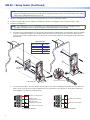
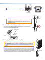
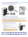
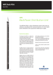
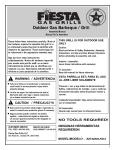
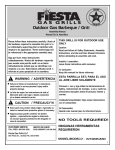
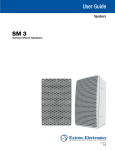
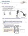
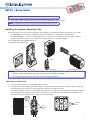
Product Category
SM 26 • Setup Guide
NOTE: Unless otherwise stated, mounting hardware is not included.
This setup guide contains installation information about the Extron SpeedMount® SM 26 speaker.
NOTE: Installation and service must be performed by authorized personnel only.
Installing the Speaker Mounting Plate
The SM 26 speaker comes with a flat mounting plate and an adapter for positioning the speaker 10° up, down, left, or right.
•
0° mounting plate — The flat (0°) mounting plate allows the speaker to be mounted flat on a suitable surface.
•
10° mounting adapter — The 10° mounting adapter allows the speaker to be installed at a 10 degree angle so that the
speaker can be pointed up, down, left, or right from an elevated position by rotating the adapter.
The mounting plate can be installed vertically or
horizontally as shown below right.
Catch Tab
10° Mounting Adapter
0° Mounting Plate
Vertical Mounting
Horizontal Mounting
NOTES:
• Observe all applicable building codes and local ordinances when installing the speaker.
• If mounting the SM 26 with the yoke mount, see the Yoke Mount Setup Guide.
Mounting to a Wall Stud
1. Locate the wall stud where the mounting plate will be installed.
2. If using the 10° mounting adapter, position the adapter over the wall stud according to how the speaker will be angled and
mark the positions of the pilot holes. See the figure below right for mounting hole locations.
If not using the adapter, position the mounting plate against the wall. The #26 arrow molded into the mounting plate indicates
the vertical midpoint of the SM 26 speaker when it is mounted on a wall stud. While positioning the mounting plate on the
wall, mark the location of two pilot holes using the holes indicated below.
Mounting
Holes
Stud
Mounting
Holes
+ + – –
33-0000-01 Rev. Ax1
LOOP
SM26 Speaker
IN
IN
LOOP
1
SM 26 • Setup Guide (Continued)
NOTE: A speaker wire access hole (see the following figures) must also be cut in the wall. Mark that hole location now
with the mounting plate positioned on the wall while ensuring that the wall stud does not interfere with the wire routing
and that the mounting plate hides the access hole.
3. Drill the mounting plate pilot holes and cut the speaker wire access hole, as previously marked.
4. Install the speaker cables into the wall before installing the speaker mounting plate. Leave enough slack in the cable.
5. Install the mounting plate.
NOTE: Since applications can vary considerably, it is assumed that the installer will exercise good judgment when
selecting the mounting location, method, and hardware. Mounting hardware is not provided.
zz
If using the 10° mounting adapter, route the speaker cable through the adapter and 0° mounting plate, attach the adapter
to the 0° mounting plate using the four included screws and washers, then attach the wire ends to the quick connect
contacts using a small screwdriver. Be sure to observe the correct polarity. Attach the mounting plate to the wall (see the
figure below).
Wire Gauge Table
Number of Wires
Maximum
per Connection Point Wire Gauge
1
2
4
12 AWG
16 AWG
18 AWG
10° Mounting
Adapter
Mounting Screws
Quick Connect Contacts
0° Mounting Plate
zz
If using only the flat plate, route the speaker cable through the rear of the mounting plate and attach the wire ends to the
quick connect contacts using a small screwdriver. Be sure to observe the correct polarity, as shown below. Attach the
mounting plate to the wall (see the figure above).
LOOP
LOOP
Red Wire (+) to Next Speaker
IN
Red Wire (+) from Amplifier
IN
Black Wire (-) from
Amplifier/Previous Speaker
IN
Black Wire (-) from Amplifier
LOOP
Black Wire (-) to Next Speaker
LOOP
IN
Red Wire (+) from
Amplifier/Previous Speaker
Loop-through Connection
2
(4) 4-40 x 3/16"
Screws
Single Speaker Connection
Product Category
NOTE: If surface mounting, route the wires through
+ + – –
33-0000-01 Rev. Ax1
LOOP
IN
IN
LOOP
alternate access points as shown at right.
0° Mounting Plate
10° Mounting Adapter
Alternate Access Point
Alternate Access Points
0.27”
(7 mm)
Good
ATTENTION: Use the appropriate mounting screws. The screw heads must
not protrude more than 0.27 inch (7 mm) above the screw holes in the
mounting plate (see the figure on the right). If the screw head protrudes too far
above the mounting plate surface, damage to the speaker may occur when
the speaker is attached.
Attaching a Secondary Support Cable
Bad
If a secondary support cable is being attached, attach the cable to the eye bolt, as shown
below. The cable end should be properly swaged.
Anchor this end to a
suitable secure point.
0.47”
(12 mm)
Attach cable here
and secure.
Secondary
Attachment
Cable
Attaching the Speaker to the Mounting Plate
ATTENTION: By default, the SM 26 speaker is shipped unlocked. When mounting the speaker
to the mounting plate, be sure that the speaker is unlocked. Failure to place the speaker in
the unlocked position prior to mounting the speaker will result in damage to the speaker lock
mechanism (see Using the Security Key to Lock and Unlock the Speaker on the next
page).
NOTE: If a secondary attachment point is being used, see the “Attaching a Secondary Support
Cable” section above for installation details before proceeding further.
Position the rear mounting slot of the speaker above the catch tab of the mounting plate, then slide the
speaker down into the mounting plate until a click is heard indicating that the speaker is secured in place
(see figure at right). When properly seated, the speaker connections are automatically made.
Catch Tab
3
Setting the Tap Selector Switch (SM 26T Model Only)
For the SM 26T model, insert a small screwdriver through the upper left portion of the front grille, as
shown below, to adjust the tap selector switch to the desired setting.
Tap Indicator
for 70 Volt
8Ω
70
100
8Ω
Unlocked
Tap Indicator
for 100 Volt
Unlocked
Locked
Twist to
Lock/Unlock
Using the Security Key to Lock and Unlock the Speaker
Insert the key into the center of the speaker grille and turn the key, as needed, so that the speaker is in the unlocked position (see
the figure above). There are three small raised “dimples” (see the figure below) on the grille surface that surrounds the keyhole.
Repeat this procedure, but set the key to the locked position to lock the speaker.
ATTENTION: The key must be rotated to the unlocked position before the speaker is attached to the mounting plate.
Failure to place the speaker in the unlocked position will result in damage to the speaker lock mechanism should an
attempt be made to mount the speaker. By default, the SM 26 speaker is shipped unlocked.
Removing the Speaker from the Mounting Plate
To remove the speaker from the mounting plate, you must unlatch the
locking mechanism.
1. Insert the security key into the keyhole of the speaker grille (see the previous
section) and turn the key to the unlock position.
2. Remove the security key.
3. Apply pressure to the grille with your finger over the “dimpled” keyhole to
unlatch the speaker from the mounting plate while lifting up on the speaker
(see figure at right).
Press to Release
ATTENTION: To avoid damaging or scratching the grille finish, do not
use tools or sharp instruments to depress the unlocking mechanism
hidden behind the center of the grille.
Extron Headquarters
+1.800.633.9876 (Inside USA/Canada Only)
Extron USA - West
Extron USA - East
+1.714.491.1500+1.919.863.1794
+1.714.491.1517 FAX
+1.919.863.1797 FAX
Extron Europe
+800.3987.6673
(Inside Europe Only)
+31.33.453.4040
+31.33.453.4050 FAX
Extron Asia
+800.7339.8766
(Inside Asia Only)
+65.6383.4400
+65.6383.4664 FAX
Extron Japan
+81.3.3511.7655
+81.3.3511.7656 FAX
Extron China
+4000.398766
Inside China Only
+86.21.3760.1568
+86.21.3760.1566 FAX
Extron Middle East
+971.4.2991800
+971.4.2991880 FAX
© 2013 Extron Electronics All rights reserved. www.extron.com
4
Extron Korea
+82.2.3444.1571
+82.2.3444.1575 FAX
Extron India
1800.3070.3777
Inside India Only
+91-80-3055.3777
+91 80 3055 3737 FAX
68-2164-50
Rev. B
09 13