1
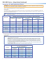
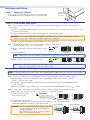
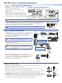
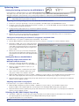
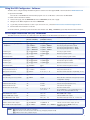
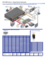
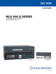
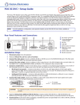
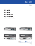
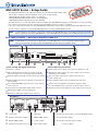
MLS 608 D Series • Setup Guide The Extron MLS 608 D Series are eight input, multi-format AV switchers with ProDSP™ audio and are able to integrate analog and digital sources. There are three models: • MLS 608 D (with variable preamp output - no amplifier) • MLS 608 D MA (with 40 watt 70 volt mono power amplifier) • MLS 608 D SA (with 2 x 20 watt stereo power amplifier) This guide allows you to easily and quickly setup and configure your MLS 608 D using step by step instructions. It covers performing basic operations using the front panel controls and selected Simple Instruction Set (SIS™) commands. It also gives connection information for the MTP HDMI U R twisted pair receiver, which is supplied with the MLS 608 D Series unit. See rear cover for a diagram of a typical MLS 608 D application, showing the MLS 608 D SA model. NOTE: For full installation, configuration, and operation details for all MLS 608 D models, see the MLS 608 D Series User Guide, and for complete details on the MTP HDMI U R, see the MTP HDMI U R User Guide, both available at www.extron.com. Rear Panel Features — MLS 608 D and MTP HDMI U R NOTE: The MLS 608 D SA, as shown below, is representative of the MLS 608 D Series. It has the maximum number and type of connectors and features of the three models. The MLS 608 D model lacks the power amplifier output. 3 MLS 608 D SA 6 14 MLS 608 D SA 50/60 Hz CONFIGURABLE ANALOG INPUTS 1 DIGITAL INPUTS ANALOG OUTPUT MTP + AUDIO L 1 1 BUFFERED OUTPUT 2 3 +12 V OUT R RS-232 INSERT L 3 Tx Rx R AUDIO OUTPUTS 2 L 5 8 7 L 2 DIGITAL OUTPUT 6 5 AUDIO INPUTS R N/A N/A 100-240V L 6 R L 7 R R L 8 4/8 OHM - 20W x 2 + 48V MIC/LINE 1 2 R L 1 R L 2 R +12V Tx Rx 1 2 4 (MTP) VIDEO + RS-232 PWR OUT= 12W 1.2A MAX RS-232 HOST PWR OUT = 7.2 W 1 2 4 7 5 8 9 Power, Analog, and Digital Connections 10 11 12 13 Audio and RS-232 Connections a AC power connector i Audio inputs: 5-pole captive screw connectors (inputs 1-3, 5-8) b RGB, component/S-video/composite inputs: 15-pin HD j Mic/line level audio inputs (1-2): 3-pole captive screw connectors c Buffered output: 15-pin HD connector (tied only to input 1) k Line level audio output: 5-pole captive screw connectors d Universal MTP RJ-45 connector (input 4, see rear page for l Power amplifier output connector (MA and SA units only) e 12 V output MTP/HDMI U R power source: 2-pole captive m RS-232 control/configuration port and +12 V power output f Analog video and audio MTP output: RJ-45 connector g Digital inputs: HDMI connectors (inputs 5-8) h Digital video and RS-232 outputs: RJ-45 connectors n RS-232 insertion pass-through port: 5-pole captive screw connector connectors (inputs 1-3, see rear page for pinout details) and phantom power LEDs (audio outputs 1-2) pinout details) screw connector (for optional MLC power source): 5-pole captive screw connector K MTP/HDMI U R DIGITAL OUTPUT DIGITAL INPUT 1 R-Y Y VID MTP INPUT B Power input Digital signal inputs (1 and 2) Digital (HDMI) output RS-232 pass-through connector C D E MTP input RGBHV, RGBS output* S-video output* Mono audio output RGB SPARE MONO AUDIO 1 2 PASS THRU Tx Rx A Tx Rx B-Y RS-232 HDMI I RS-232 2 POWER 12V 0.8A MAX J Y/C ANALOG OUTPUTS G A F H RS-232 port (analog side), not used in MLS 608 D system Composite video output* Component video (R-Y, Y, B-Y) output* * = Analog outputs 1 MLS 608 D Series • Setup Guide (Continued) Twisted Pair (TP) Cable Transmission Distance CAUTION: Do not connect the MTP cable to any LAN port, telecommunications network, or digital video output port. Likewise, do not connect a LAN cable to any MTP or digital video output port. There are different maximum distances for analog and digital signals. Analog signals — The maximum distance is determined by the frequency and resolution of the signal that is input to the MLS 608 D. The table below specifies the recommended maximum transmission distances using Extron Enhanced Skew-Free™ A/V UTP cable or UTP CAT 5, 5e, or 6 cable, terminated with RJ-45 connectors. NOTE: The transmission distance varies greatly depending on the signal resolution and on the type of cable, graphics card, and display used in the system. Maximum Transmission Distances for Analog Signals at 60 Hz for MLS 608 D Video Format With Pre-Peak Off Feet (Meters) With Pre-Peak On Feet (Meters) Max. Distance (High Quality) Feet (Meters) Max. Distance (Variable Quality) Feet (Meters) Input (from source) Output (to receiver) Input Output Composite, S-video <300 (90) >350 (105) 700 (215) 700 (215) 700 (215) 800 (245) Component Video <300 (90) >350 (105) 700 (215) 700 (215) 750 (230) 750 (230) 1024x768* <300 (90) >350 (105) 450 (135) 450 (135) 550 (170) 550 (170) 1280x1024* <250 (75) >300 (90) 350 (105) 350 (105) 450 (135) 450 (135) 1600x1200* <250 (75) >300 (90) 300 (90) 300 (90) 450 (135) 450 (135) 1920x1200 <200 (60) >250 (75) 300 (90) 250 (75) 400 (120) 400 (120) HDTV 720p <250 (75) >300 (90) 400 (120) 400 (120) 500 (150) 500 (150) HDTV 1080p <250 (75) >250 (75) 300 (90) 250 (75) 400 (120) 400 (120) * same spec at 75 Hz For any transmission distances beyond 350 feet (100 m), turn on the pre-peak function on the transmitting device (MTP transmitter). Digital signals — NOTES: • The transmission distance varies greatly depending on the signal resolution and on the type of cable, graphic card, and display used in the system. • DO NOT use Extron UTP23SF-4 Enhanced Skew-Free A/V cable to link the switcher digital output port and the MTP/HDMI U R receiver. Use of this cable will cause problems with the digital signal input side of the receiver. • For resolutions of 1600x1200, 1920x1200, and 1080p, Extron strongly recommends STP201 cable, or equivalent. STP201 cable consists of four individually shielded copper pairs and an overall braided shield that help reduce crosstalk and extend these resolutions up to 150 feet (45 m). • It is important to ensure the cable from output 1 on the switcher (see page 1, h ) is connected to input 1 on the receiver (see page 1, ). Likewise, output 2 on the switcher must be connected to input 2 on the receiver. Maximum Transmission Distance for Digital Signals at 60 Hz from MLS to MTP/HDMI U R 2 Resolution UTP CAT 5/5e/6 Feet (Meters) STP CAT 5/5e/6 Feet (Meters) STP201 Feet (Meters) 1024x768 200 (61) 200 (61) 200 (61) 1600x1200 100 (38) 125 (38) 150 (46) 1920x1200 100 (38) 125 (38) 150 (46) 720p 200 (61) 200 (61) 200 (61) 1080i 200 (61) 200 (61) 200 (61) 1080p 100 (38) 125 (38) 150 (46) Installation and Cabling Step 1 — Mount the Switcher 2U Rack Mount Bracket (use four lower holes) Turn off or disconnect all equipment power sources and rack mount the MLS 608 D using the two supplied brackets (see image at right). Step 2 — Connect MLS 608 D Inputs Video — Connect inputs from video sources to the applicable connectors marked “Inputs” (see b, d, and g on page 1 for connector types). b Inputs 1-3 — RGB (RGBHV, RGBs, or RGsB), component (bi- or tri-level), S-video, or composite video signals. See rear cover for connector pin-out table. d Input 4 — Universal MTP (video and audio) input on CAT 5, 5e, or 6 twisted pair cabling CAUTION: Do not connect the MTP cable to any LAN port, telecommunications network, or digital video output port. Likewise, do not connect a LAN cable to any MTP, or digital video output port. g Inputs 5-8 — Digital HDMI (HDMI 1.3) and DVI-D (using an adapter cable) inputs Audio — Connect inputs from audio sources to the applicable connectors marked “Inputs” (see d, i, and j on page 1 for connector types). Tip d Input 4 (see d above). Do not tin the wires! Tip Sleeve R Inputs 1-3 and 5-8 (line level analog stereo). Wire as shown at right. Tip Ring Sleeve (s) Tip Ring Sleeve L i (5 mm) MAX. Balanced Input Unbalanced Input (high impedance) (high impedance) NOTE: HDMI inputs 5-8 have the capability to de-embed source input audio (default setting). j (5 mm) MAX. Mic/line inputs 1-2 (mono). Wire as shown at right. Tip Tip Ring Sleeve Sleeve Do not tin the wires! Unbalanced Mic Input Balanced Mic Input NOTE: These inputs have +48 V phantom power available, and the LEDs light when power is present. This power is turned on or off via software. “Off” is the default setting. Step 3 — Connect MLS 608 D Outputs NOTE: For TP cables with RJ-45 connectors, use the same standard (T568A or T568B) at both ends. See rear cover for details. Video — Connect video output devices to the applicable connectors marked “Outputs” (see c, f and h on page 1). c Buffered output — This signal is always tied to input 1, RGB (RGBHV, or RGBs), component (bi- or tri-level), S-video, or composite video signals. f Analog video output from inputs 1-4, output on CAT 5, 5e, or 6 twisted pair cabling to the MTP/HDMI U R receiver (see on page 1) h Digital video and RS-232 outputs on CAT 5, 5e, or 6 twisted pair cabling to MTP/HDMI U R receiver (see on page 1) Audio — Connect audio output devices to the applicable connectors marked “Outputs” (see f, k and l on page 1). l Power amplifier output, either as For unbalanced audio, connect the sleeve(s) to the ground contact. DO NOT connect the sleeve(s) to the negative (-) contacts. Sleeve(s) Tip NO Ground Here Tip Ring Sleeve(s) Tip Ring Unbalanced Output AUDIO L R Wire as shown at right. AUDIO L R f MTP analog audio output (line level mono only) on CAT 5, 5e, or 6 twisted pair cabling Tip CAUTION k Two line level audio outputs. NO Ground Here Balanced Output 2-channel stereo, 20 watts per channel (MLS 608 D SA model) or mono audio, 40 watts per channel, 70 volts (MLS 608 D MA model). Wire as shown at below right. MLS 608 D SA Wiring MLS 608 D MA Wiring To 70 V Speaker L 5 mm Captive Screw NC R or to ground. Doing so will short the outputs and damage the amplifier. • Do not short the “ +” and “_” connectors together. Doing so will damage the amplifier. To 4/8 Ohm Speaker Load NC CAUTIONS: • Do not connect L and R output channels to each other, 5 mm Captive Screw 3 MLS 608 D Series • Setup Guide (Continued) Step 4 — Connect Outputs from MTP/HDMI U R Digital video — Connect a display to the HDMI connector for digital video output. Component Video – Connect to these 3 BNCs. RS-232 R-Y Y Tx Rx B-Y VID RGBHV and RGBS – Connect to this VGA connector. SPARE Unbalanced Output MONO AUDIO 1 2 Mono output 1+ Mono output 1Sleeve(s) Mono output 2+ Mono output 2- Y/C ANALOG OUTPUTS S-video – Connect to this mini DIN connector. Mono Audio – Connect to this captive screw connector. Do not tin the wires! MONO AUDIO L R RGB Mono output 1 NO GROUND. Sleeve(s) Mono output 2 NO GROUND. MONO AUDIO L R Analog video — Connect the analog outputs as shown at right. Audio — Connect a suitable audio device, such as powered speakers, to the 5-pole captive screw audio output connector for a balanced or unbalanced, dual mono audio signal. Wire connector as shown at right. RS-232 Control (Analog Side) – NOT USED IN THE MLS 608 D SYSTEM. Composite Video – Connect to this BNC. Balanced Output Wire the audio connector as shown above. NOTE: The audio signal is detected on the MTP input and then is distributed to the audio connector for output. RS-232 control (digital side) — Connect a serial communications port on a display device to the 3.5 mm, 3-pole captive screw connector (labeled RS-232 pass-thru) for pass-through RS-232 bidirectional communication. Wire the connector as shown at right. RS-232 Device Pins Rx Tx Tx Rx MTP/HDMI RS-232 Pass-thru port Ground NOTE: The RS-232 control port on the analog side is not used in the MLS 608 D system. RS-232 Host CONFIGURABLE ANALOG INPUTS 1 DIGITAL INPUTS ANALOG OUTPUT MTP + AUDIO L 1 2 3 +12 V OUT 1 7 L 6 R R L 7 L 8 R R MIC/LINE 1 2 + 48V 4/8 OHM - 20W x 2 L 1 R L 2 R +12V Tx Rx RS-232 HOST PWR OUT = 7.2W RS-232/IR NOTE: You must connect a ground CM/IR/SCP A B C IR/SERIAL OUT Rx Tx GROUND GROUND +12V IN 5 6 C Tx/IR GROUND B RELAYS NORMALLY OPEN Tx/IR GROUND 3 4 COMMON 1 2 A A B C D E COMMON COMMON +12V OUT GROUND A B C D E Tx/IR GROUND DISPLAY CONT MOD IR IN SCP COM T x / IR Rx GROU N D PWR SN S MLS 608 D SA Rear Panel GROU N D +12V OU T MLS 608 D rear panel RS-232 Host port 2 VIDEO + RS-232 PWR OUT= 12W A B MLS PWR RS-232 12V MLC 226 IP Bottom Panel +12 VDC input Ground ( ) Ground ( ) B Receive (Rx) A Transmit (Tx) Transmit (Tx) B Receive (Rx) A NOTE: If you use cable that has a drain wire, tie the drain wire to ground at both ends. Tx power a controller, for example an MLC 226 IP and a connected IRCM-DV+. Tx Rx R AUDIO OUTPUTS L 5 4 (MTP) 1.2A MAX Rx NOTE: The ‘+’ and ‘-’ pins on this connector can be used to L 3 R 1 wire between the MLC and MLS. RS-232 protocol (default values): • 38400 baud •1 stop bit • no parity • 8 data bits • no flow control L 2 2 8 NOTE: This serial port is independent of the front panel configuration port. Both may be used for MLS control. RS-232 INSERT AUDIO INPUTS R DIGITAL OUTPUT 6 5 BUFFERED OUTPUT N/A N/A 50/60 Hz A B MLS +12V IN Tx Rx MLS 608 D SA 100-240V GROUND RS-232 control — Connect a host computer or control system (such as an optional MLC 226) to the 5-pin connector (see m on page 1) for MLS switcher configuration and control via RS-232 using Extron software or Simple Instruction Set (SIS) commands. Wire the MLS as shown at right. GROUND Step 5 — Connect Control Devices MLC's MLS and Power ports PWR RS-232 12V RS-232 INSERT Tx Rx Transmit (Tx) Receive (Rx) Ground ( ) GROUND +12V OUT Tx/IR Rx N/A N/A GROUND PWR SNS RS-232 Insert port (optional) — Connect an optional control device (for example an MLC 226 IP via the RS-232 display control port) to the 5-pin connector (see n on page 1) for pass through RS-232 communication to a connected projector or display device. Wire the connection as shown at right. MLS 608 D rear panel RS-232 Insert port DISPLAY RS-232/IR MLC 226 Display port Step 6 — Connect Power MLS 608 D — Plug in a standard IEC power cord from a 110 - 240 VAC, 50 - 60 Hz power source into the receptacle (see a on page 1). Optional — Connect the 2-pole power connector (see e on page 1) for remote power to an MTP transmitter or receiver. Wire the connection as shown at right. Optional — Connect the “+” and ”-” pins on the RS-232 connector (see m on page 1) for remote power to an optional controller (such as the MLC 226). See second note, step 4 above. MTP/HDMI U R — Connect the 2-pole 3.5 millimeter captive screw connector from the 12 VDC, 1.0 A external power supply (provided) to this receptacle on the rear panel, or connect to the 2-pole power connector (see e on page 1) on the MLS 608 D. Wire connector as shown at right. For both devices, when power is applied the front panel power LED lights. 4 Smooth Ridges A A 2-pole Captive Screw Connector Tie Wrap Power Supply Output Cord 3 SECTION A–A Optimizing Video Setting the Peaking and Level on the MTP/HDMI U R AUDIO RS-232 ANALOG SIGNAL VID Y/C YUV RGB RGB LEVEL PEAKING DIGITAL SIGNAL Image sharpness is adjusted with the front panel Peaking adjustment knob. This applies only to the analog side of the device. Increased peaking compensates for mid- and high-frequency detail loss. Minimum setting (full counterclockwise) is zero peaking. Image brightness is adjusted using the Level adjustment knob. MTP/HDMI U R NOTE: To avoid possible video loss due to errors in the video format detection, the user should always start with minimal level and peaking, then increase values as required. Adjusting level and peaking between the MLS 608 D and the receiver 1. Connect an oscilloscope (preferred) or a monitor (acceptable) to the RGB output of the MTP/HDMI U R receiver. 2. If using an oscilloscope, apply a white field test pattern to inputs 1, 2, or 3 on the MLS 608 D. The Extron VTG 300 or VTG 400 is recommended to provide the test pattern. 3. If using a monitor, apply a grayscale or color bars test pattern to the input. NOTE: The signal applied should be an RGB signal. 4. Observe the oscilloscope (or monitor) while you adjust the front panel input level and peaking controls to compensate for signal loss between the MLS 608 D and the MTP/HDMI U R. Setting level and peaking via software if using Input 4 on the MLS 608 Follow the steps 1 to 3 as given in “Adjusting level and peaking...” above. Then: 1. Start the DSP Configurator software program and connect to your device. See page 7 for software installation details. 2. Click View > Video I/O (or press <F4>); this changes the window to the MLS workspace view. Double click on the MTP on the input 4 (left) side of the workspace view. The Input MTP Settings dialog box appears (see image at right). 3. Observe the oscilloscope (or monitor) and adjust the level using the slider. Adjust the peaking by using the up and down arrows. Disconnect test equipment when finished. Setting the Skew on the MLS 608 D Adjusting output skew between the MLS 608 D and the receiver: 1. Connect an oscilloscope (preferred) or a monitor (acceptable) to the RGB output on the MTP/HDMI U R. 2. Apply a crosshatch test pattern to input 1, 2, or 3 on the MLS 608 D. 3. Use the test equipment or examine the video image with a critical eye to determine which video signal (red, green, or blue) is most shifted to the left. 4. Within the DSP Configurator program, click View > Video I/O (or press <F4>) to access the MLS workspace view. Double-click MTP on the output (right) side of the workspace view. The Output MTP Settings dialog box appears (see image above). 5. Adjust the furthest left video signal by using the up and down arrows for the relevant signal color, and repeat as needed until all three colors are aligned correctly. Adjusting input skew if using Input 4 Follow the steps 1 to 3 as given in “Output skew”, above. Then: 1. Within the DSP Configurator program, click View > Video I/O (or press <F4>) to access the MLS workspace view. Double-click MTP on the output (right) side of the workspace view. The Output MTP Settings dialog box appears. 2. Adjust the furthest left video signal by using the up and down arrows for the relevant signal color, and repeat as needed until all three colors are aligned correctly. Selecting the MLS 608 D Output Prepeaking 1. Click View > Video I/O (or press <F4>); this changes the window to the MLS workspace view. Double-click on the MTP on the output (right) side of the workspace view. The Output MTP Settings dialog box appears. 2. Toggle the Pre-peak box on or off as desired. NOTE: For other video configurations, such as RGB delay or input video format swapping, see the DSP Configurator Help file. 5 MLS 608 D Series • Setup Guide (Continued) Front Panel Features All models have the following front panel features: SOURCE SELECTION R PC DOC CAM 1 2 CONFIG 3 VOLUME AUX VID LAPTOP Blu-ray 4 5 6 7 MIC VOLUME 8 MLS 608 D AV Switcher with ProDSP™ 1 2 5 4 3 a Power/reset status LED b Reset button (recessed) c USB configuration port 6 d Input selection buttons (8) e Program volume control (adjustment knob) f Mic volume control (adjustment knob) Front Panel Operation NOTE: For operation details for all models, see the MLS 608 D Series User Guide, available at www.extron.com. a Power/reset status LED — This LED lights green when power is applied, and amber when in standby mode. It also indicates the reset mode when the reset button is being operated (see below). b Reset button — In order to reset the MLS switcher to one of two available reset modes via the front panel, press and hold this recessed button in and observe the LED for confirmation of unit resetting. Reset Mode 1, Use factory firmware — To reset temporarily to the factory default firmware, press and hold the reset button in while applying power to the unit. NOTES: • After a Mode 1 reset, update the firmware to the latest version. DO NOT use the factory firmware resulting from the reset. Factory firmware must be re-uploaded if that is the version to be used. • If you do not want to update the firmware, recycling the power reinstates the firmware version used before the Mode 1 reset. Reset Mode 5, Reset to factory default — To reset the device to factory defaults (with the exception of the firmware), press and hold in the reset button for approximately 9 seconds, until the LED blinks three times (once at 3 seconds, 6 seconds, and 9 seconds), and then release. Within 1 second press and release the reset button once (<1 second). Nothing will happen if the momentary press is not made within 1 second. c Front panel mini USB configuration port — Connect a computer to this port, using a mini USB cable (not supplied), for configuration, control, and firmware upgrades. NOTE: For details of device configuration via software, SIS commands, and firmware updating for all models, see the DSP Configurator Help file or the MLS 608 D Series User Guide, both available at www.extron.com. d Source selection buttons — Use these buttons to select or switch between inputs. The button lights amber to indicate which input is active. e Program volume adjustment knob — Use this to set or adjust the program output volume (attenuation, from -100 dB to 0 dB) as desired. The LEDs indicate the volume level (all off at -100 dB, all on at -4 to 0 dB). Rotate the knob clockwise to increase volume, counter-clockwise to decrease volume. See table at right for LED/dB values. VOLUME LED equivalent dB value -4 to 0 -9 to -5 f Mic volume adjustment knob — Use this knob to set or adjust the volumes of the two mic inputs (see page 1, j ) as desired. The LEDs indicate the volume level. -14 to -10 Rotate the knob clockwise to increase volume, counterclockwise to decrease volume. -29 to -20 NOTE: The system and microphone volume settings and adjustments can be made using Extron DSP Configurator program or via SIS commands. See the MLS 608 D User Guide for details. -19 to -15 -49 to -30 - 69 to -50 -99.9 to -70 -100 (all LEDs off) 6 Using the DSP Configurator™ Software The MLS can be configured using the DSP Configurator software from the supplied DVD or downloaded from www.extron.com. To upload from the DVD: Place the disc in the DVD drive and install the program onto a local PC that is connected to the MLS 608 D. To download from the Extron website: 1. At the home page, click the Download tab and click Software (at left side of page). 2. Navigate to the DSP Configurator file and click Download. 3. Log in with your Extron website account. If you do not have one, contact the Extron S3 Sales and Technical Support Hotline. 4. Download the file and install it on the PC. To use the software, open the program and at the main window click Help, Contents (or press F1) and follow the instructions. Basic Simple Instruction Set (SIS) Commands The table below lists some basic SIS commands for the MLS 608 D. See the MLS 608 D User Guide for a complete SIS list. Commands ASCII command (host to switcher) Response (switcher to host) Additional description Input selection — video and audio X!! Chn X!] Select video and audio from inputs 0-8 source X!. Set program volume gain (dB) value Ed1*X2(GRPM} GrpmD01*X2(] Set a program gain value to X2(. Ed1*0GRPM} Ed1*-100GRPM} Ed1*-1000GRPM} GrpmD01*+00000] GrpmD01*-00100] GrpmD01*-01000] Sets the program gain value to 0 dB. Sets the program gain value to -10 dB. Sets the program gain value to -100 dB. Increment gain E d1*X2*+GRPM} GrpmD01*X2(] Increase program volume. Decrement gain E d1*X2*-GRPM} GrpmD01*X2(] Decrease program volume. View master value E d1GRPM} X2(] View the current program volume. Set Mic volume gain (dB) value E d2*X2(GRPM} GrpmD02*X2(] Set a microphone volume gain value to X2(. Increment gain E d2*X2*+GRPM} GrpmD02*X2(] Increase microphone volume. Decrement gain E d2*X2*-GRPM} GrpmD02*X2(] Decrease microphone volume. View master value E d2GRPM} X2(] View the current microphone volume. Turn power save mode off E 0 PSAV} Psav0] Turn power save mode off. Turn power save mode on E 1 PSAV} Psav1] Turn power save mode on. Query power save status E PSAV} 0 ] (or) 1 ] View the current status (0 = off [default], 1= on). Reset all video and audio settings to factory default E ZXXX} Zpx] Resets all video and audio settings. Reset all settings to factory default E ZQQQ} Zpq] Resets all video and audio settings and protected configuration settings. Enable Executive mode 1 1X Exe1] Lock the front panel buttons and knobs. Enable Executive mode 2 2X Exe2] Lock the front panel buttons only. Disable Executive mode 0X Exe0] Unlock all the front panel. View Executive mode status X 0 ] (or) 1 ] (or) 2 ] View the current status: 0 = off [default]; 1 = on, lock all buttons and knobs; 2 = on, lock input buttons only. Mute HDMI audio output 1Z Amt1 ] Mute HDMI audio output. Unmute HDMI audio output 0Z Amt0 ] Unmute HDMI audio output. View HDMI audio mute status Z 0] (or) 1] View mute status (0 = mute off, 1 = mute on). Mute overall volume output E D5*1GRPM} GrpmD05*1 ] Mute overall volume output (1 = on). Unmute overall volume output E D5*0GRPM} GrpmD05*0 ] Unmute overall volume output, (0 = off). View overall volume output status E D5 GRPM} +00000] (or) +00001] View mute status (+00000 = mute off, +00001 = mute on). Examples: NOTE: X! = Input connection, 0 – 8, 0 = no connection X2* = Incremental or decremental value in 0.1 dB steps, multiply by 10 (10 = 1.0 dB) X2( = Master volume values, multiplied by 10 7 MLS 608 D Series • Setup Guide (Continued) Typical Application for MLS 608 D Series, Showing the MLS 608 D SA Extron MLC 226 IP DV+ Microphones Extron MTP T 15HD A D CH Transmitter DIO Enhanced MediaLink Controller w/ IP Link 003 IN AU CH R IN 003 TE MPU TCP/IP Network CO Projector Control & VC D RO CO DVD DV ER VCR TUN NU P STO ME ER SE ENT WD LE Switcher Control TO AU GE IMA Y LA SP DI R VC 1 4 2 5 3 6 EW Y PLA NEX V/R PRE MLC PC OP PT LA 8D LU VO RT N/A N/A IN + Ethernet A/V Resource Management and Remote Control Application SA SE Tx DV GlobalViewer® IR 60 -232 RS IP IG NF CO ME Laptop MLS 226 C DO M CA F OF ON D PAU T/F TIT X AU EO VID DV Ethernet Tx L NT R Rx 2V +1 0W S UT TP O DI OU 4/8 x2 M-2 Tx -232 RS ST HO OH AU 2 L V + 48 3 R L TS PU IN O DI 2 R AU L MI 1 C/ E LIN 2 L 1 R Rx R T= 7.2 W R OU PW Screen Control 1 2 8 R L 1 R 7 R L L 6 R L UT TP L OU TA GI DI 5 R L 2 1 TS PU TA GI DI L IN 6 2 -23 EO + RS VID 8 5 UT TP OG OU AL AN MTP + O DI TS PU OG IN +12 V OU T AL LE AN AB UT UR IG TP NF CO Extron MLS 608 D SA ED ER FF OU ) TP Extron SI 26 Digital Video + RS-232 7 AU Surface Mount Speakers T= R OU PW12W 4 (M BU 1 /60 V 3 Hz 50 40 -232 0-2 10 RS 2 MediaLink Switcher E AR SP MTP + Audio Tx Rx NO O DI AU 2 MO 1 VID X A MA 3.2 S UT TP OU C Y/ Y SS T PU MI HD OG AL AN T 2 -23 RU RS TH L IN TA RG R- L OU TA PA DIGI B Y UT TP DIGI Extron MTP/HDMI U R Receiver Y B- Tx Rx 2 1 PU MTP IN Projector Control R WE PO X V 12 A MA 0.8 HDMI + Audio HDMI + Audio PC Blu-ray Document Camera Projector Laptop Connector and Cable Information 10 Inputs 1-3 5 1 6 Twisted Pair RJ-45 Cabling RJ-45 Connector Pins: 12345678 15 11 HD15 Pin Locations Female Pin RGBHV RGBs RGsB RsGsBs Component S-video 1 Red Red Red Red/Sync R-Y Chroma 2 Green Green Green/Sync Green/Sync Y Luma 3 Blue Blue Blue Blue/Sync B-Y 4 ID Bit ID Bit ID Bit ID Bit 5 N/C N/C N/C N/C 6 Red Return Red Return Red Return Red Return R-Y Return C Return 7 Green Return Green Return Green Return Green Return Y Return L Return 8 Blue Return Blue Return Blue Return Blue Return B-Y Return 10 Ground Ground Ground Ground 11 ID Bit ID Bit ID Bit 12 ID Bit ID Bit ID Bit 13 H Sync C Sync 14 V Sync 15 ID Bit Composite Video Insert Twisted Pair Wires Pin T568A Wire Color T568B Wire Color 1 White-green White-orange 2 Green Orange 3 White-orange White-green 4 Blue Blue ID Bit 5 White-blue White-blue ID Bit 6 Orange Green 7 White-brown White-brown 8 Brown Brown Video Return 9 ID Bit Extron Headquarters +1.800.633.9876 (Inside USA/Canada Only) Extron USA - West Extron USA - East +1.714.491.1500+1.919.863.1794 +1.714.491.1517 FAX +1.919.863.1797 FAX ID Bit ID Bit Extron Europe +800.3987.6673 (Inside Europe Only) +31.33.453.4040 +31.33.453.4050 FAX Extron Asia +800.7339.8766 (Inside Asia Only) +65.6383.4400 +65.6383.4664 FAX Extron Japan +81.3.3511.7655 +81.3.3511.7656 FAX Extron China +4000.398766 (Inside China Only) +86.21.3760.1568 +86.21.3760.1566 FAX Extron Middle East +971.4.2991800 +971.4.2991880 FAX © 2011 Extron Electronics All rights reserved. www.extron.com 8 Extron Korea +82.2.3444.1571 +82.2.3444.1575 FAX Extron India 1800.3070.3777 (Inside India Only) +91-80-3055.3777 +91 80 3055 3737 FAX 68-1893-50 Rev C 11 11