1
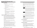
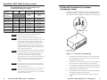
User’s Guide
VersaTools® MTP 15HD A Series
www.extron.com
Extron Electronics, USA
1230 South Lewis Street
Anaheim, CA 92805
800.633.9876 714.491.1500
FAX 714.491.1517
Extron Electronics, Europe
Beeldschermweg 6C
3821 AH Amersfoort, The Netherlands
+800.3987.6673 +31.33.453.4040
FAX +31.33.453.4050
Extron Electronics, Asia
135 Joo Seng Rd. #04-01
PM Industrial Bldg., Singapore 368363
+800.7339.8766 +65.6383.4400
FAX +65.6383.4664
© 2007 Extron Electronics. All rights reserved.
Extron Electronics, Japan
Kyodo Building, 16 Ichibancho
Chiyoda-ku, Tokyo 102-0082
Japan
+81.3.3511.7655 FAX +81.3.3511.7656
High Resolution Video and Audio
Mini Twisted Pair Transmitters and Receivers
68-956-01 Rev. C
03 07
Precautions
Safety Instructions • English
This symbol is intended to alert the user of important
operating and maintenance (servicing) instructions
in the literature provided with the equipment.
This symbol is intended to alert the user of the
presence of uninsulated dangerous voltage within
the product's enclosure that may present a risk of
electric shock.
Caution
Read Instructions • Read and understand all safety and operating
instructions before using the equipment.
Retain Instructions • The safety instructions should be kept for future
reference.
Follow Warnings • Follow all warnings and instructions marked on the
equipment or in the user information.
Avoid Attachments • Do not use tools or attachments that are not
recommended by the equipment manufacturer because they may be
hazardous.
Consignes de Sécurité • Français
Ce symbole sert à avertir l’utilisateur que la
documentation fournie avec le matériel contient des
instructions importantes concernant l’exploitation
et la maintenance (réparation).
Ce symbole sert à avertir l’utilisateur de la présence
dans le boîtier de l’appareil de tensions dangereuses
non isolées posant des risques d’électrocution.
Attention
Lire les instructions• Prendre connaissance de toutes les consignes de
sécurité et d’exploitation avant d’utiliser le matériel.
Conserver les instructions• Ranger les consignes de sécurité afin de
pouvoir les consulter à l’avenir.
Respecter les avertissements • Observer tous les avertissements et
consignes marqués sur le matériel ou présentés dans la documentation
utilisateur.
Eviter les pièces de fixation • Ne pas utiliser de pièces de fixation ni
d’outils non recommandés par le fabricant du matériel car cela
risquerait de poser certains dangers.
Sicherheitsanleitungen • Deutsch
Dieses Symbol soll dem Benutzer in der im
Lieferumfang enthaltenen Dokumentation
besonders wichtige Hinweise zur Bedienung und
Wartung (Instandhaltung) geben.
Dieses Symbol soll den Benutzer darauf aufmerksam
machen, daß im Inneren des Gehäuses dieses
Produktes gefährliche Spannungen, die nicht isoliert
sind und die einen elektrischen Schock verursachen
können, herrschen.
Achtung
Lesen der Anleitungen • Bevor Sie das Gerät zum ersten Mal verwenden,
sollten Sie alle Sicherheits-und Bedienungsanleitungen genau
durchlesen und verstehen.
Aufbewahren der Anleitungen • Die Hinweise zur elektrischen Sicherheit
des Produktes sollten Sie aufbewahren, damit Sie im Bedarfsfall darauf
zurückgreifen können.
Befolgen der Warnhinweise • Befolgen Sie alle Warnhinweise und
Anleitungen auf dem Gerät oder in der Benutzerdokumentation.
Keine Zusatzgeräte • Verwenden Sie keine Werkzeuge oder Zusatzgeräte,
die nicht ausdrücklich vom Hersteller empfohlen wurden, da diese eine
Gefahrenquelle darstellen können.
Instrucciones de seguridad • Español
Este símbolo se utiliza para advertir al usuario sobre
instrucciones importantes de operación y
mantenimiento (o cambio de partes) que se desean
destacar en el contenido de la documentación
suministrada con los equipos.
Este símbolo se utiliza para advertir al usuario sobre
la presencia de elementos con voltaje peligroso sin
protección aislante, que puedan encontrarse dentro
de la caja o alojamiento del producto, y que puedan
representar riesgo de electrocución.
Precaucion
Leer las instrucciones • Leer y analizar todas las instrucciones de
operación y seguridad, antes de usar el equipo.
Conservar las instrucciones • Conservar las instrucciones de seguridad
para futura consulta.
Obedecer las advertencias • Todas las advertencias e instrucciones
marcadas en el equipo o en la documentación del usuario, deben ser
obedecidas.
Evitar el uso de accesorios • No usar herramientas o accesorios que no
sean especificamente recomendados por el fabricante, ya que podrian
implicar riesgos.
Warning
Power sources • This equipment should be operated only from the power source
indicated on the product. This equipment is intended to be used with a main
power system with a grounded (neutral) conductor. The third (grounding) pin is
a safety feature, do not attempt to bypass or disable it.
Power disconnection • To remove power from the equipment safely, remove all
power cords from the rear of the equipment, or the desktop power module (if
detachable), or from the power source receptacle (wall plug).
Power cord protection • Power cords should be routed so that they are not likely to
be stepped on or pinched by items placed upon or against them.
Servicing • Refer all servicing to qualified service personnel. There are no userserviceable parts inside. To prevent the risk of shock, do not attempt to service
this equipment yourself because opening or removing covers may expose you to
dangerous voltage or other hazards.
Slots and openings • If the equipment has slots or holes in the enclosure, these are
provided to prevent overheating of sensitive components inside. These openings
must never be blocked by other objects.
Lithium battery • There is a danger of explosion if battery is incorrectly replaced.
Replace it only with the same or equivalent type recommended by the
manufacturer. Dispose of used batteries according to the manufacturer's
instructions.
Avertissement
Alimentations• Ne faire fonctionner ce matériel qu’avec la source d’alimentation
indiquée sur l’appareil. Ce matériel doit être utilisé avec une alimentation
principale comportant un fil de terre (neutre). Le troisième contact (de mise à la
terre) constitue un dispositif de sécurité : n’essayez pas de la contourner ni de la
désactiver.
Déconnexion de l’alimentation• Pour mettre le matériel hors tension sans danger,
déconnectez tous les cordons d’alimentation de l’arrière de l’appareil ou du
module d’alimentation de bureau (s’il est amovible) ou encore de la prise secteur.
Protection du cordon d’alimentation • Acheminer les cordons d’alimentation de
manière à ce que personne ne risque de marcher dessus et à ce qu’ils ne soient
pas écrasés ou pincés par des objets.
Réparation-maintenance • Faire exécuter toutes les interventions de réparationmaintenance par un technicien qualifié. Aucun des éléments internes ne peut être
réparé par l’utilisateur. Afin d’éviter tout danger d’électrocution, l’utilisateur ne
doit pas essayer de procéder lui-même à ces opérations car l’ouverture ou le
retrait des couvercles risquent de l’exposer à de hautes tensions et autres dangers.
Fentes et orifices • Si le boîtier de l’appareil comporte des fentes ou des orifices,
ceux-ci servent à empêcher les composants internes sensibles de surchauffer. Ces
ouvertures ne doivent jamais être bloquées par des objets.
Lithium Batterie • Il a danger d'explosion s'll y a remplacment incorrect de la
batterie. Remplacer uniquement avec une batterie du meme type ou d'un ype
equivalent recommande par le constructeur. Mettre au reut les batteries usagees
conformement aux instructions du fabricant.
Vorsicht
Stromquellen • Dieses Gerät sollte nur über die auf dem Produkt angegebene
Stromquelle betrieben werden. Dieses Gerät wurde für eine Verwendung mit
einer Hauptstromleitung mit einem geerdeten (neutralen) Leiter konzipiert. Der
dritte Kontakt ist für einen Erdanschluß, und stellt eine Sicherheitsfunktion dar.
Diese sollte nicht umgangen oder außer Betrieb gesetzt werden.
Stromunterbrechung • Um das Gerät auf sichere Weise vom Netz zu trennen,
sollten Sie alle Netzkabel aus der Rückseite des Gerätes, aus der externen
Stomversorgung (falls dies möglich ist) oder aus der Wandsteckdose ziehen.
Schutz des Netzkabels • Netzkabel sollten stets so verlegt werden, daß sie nicht
im Weg liegen und niemand darauf treten kann oder Objekte darauf- oder
unmittelbar dagegengestellt werden können.
Wartung • Alle Wartungsmaßnahmen sollten nur von qualifiziertem
Servicepersonal durchgeführt werden. Die internen Komponenten des Gerätes
sind wartungsfrei. Zur Vermeidung eines elektrischen Schocks versuchen Sie in
keinem Fall, dieses Gerät selbst öffnen, da beim Entfernen der Abdeckungen die
Gefahr eines elektrischen Schlags und/oder andere Gefahren bestehen.
Schlitze und Öffnungen • Wenn das Gerät Schlitze oder Löcher im Gehäuse
aufweist, dienen diese zur Vermeidung einer Überhitzung der empfindlichen
Teile im Inneren. Diese Öffnungen dürfen niemals von anderen Objekten
blockiert werden.
Litium-Batterie • Explosionsgefahr, falls die Batterie nicht richtig ersetzt wird.
Ersetzen Sie verbrauchte Batterien nur durch den gleichen oder einen
vergleichbaren Batterietyp, der auch vom Hersteller empfohlen wird. Entsorgen
Sie verbrauchte Batterien bitte gemäß den Herstelleranweisungen.
Advertencia
Alimentación eléctrica • Este equipo debe conectarse únicamente a la fuente/tipo
de alimentación eléctrica indicada en el mismo. La alimentación eléctrica de este
equipo debe provenir de un sistema de distribución general con conductor
neutro a tierra. La tercera pata (puesta a tierra) es una medida de seguridad, no
puentearia ni eliminaria.
Desconexión de alimentación eléctrica • Para desconectar con seguridad la
acometida de alimentación eléctrica al equipo, desenchufar todos los cables de
alimentación en el panel trasero del equipo, o desenchufar el módulo de
alimentación (si fuera independiente), o desenchufar el cable del receptáculo de
la pared.
Protección del cables de alimentación • Los cables de alimentación eléctrica se
deben instalar en lugares donde no sean pisados ni apretados por objetos que se
puedan apoyar sobre ellos.
Reparaciones/mantenimiento • Solicitar siempre los servicios técnicos de personal
calificado. En el interior no hay partes a las que el usuario deba acceder. Para
evitar riesgo de electrocución, no intentar personalmente la reparación/
mantenimiento de este equipo, ya que al abrir o extraer las tapas puede quedar
expuesto a voltajes peligrosos u otros riesgos.
Ranuras y aberturas • Si el equipo posee ranuras o orificios en su caja/alojamiento,
es para evitar el sobrecalientamiento de componentes internos sensibles. Estas
aberturas nunca se deben obstruir con otros objetos.
Batería de litio • Existe riesgo de explosión si esta batería se coloca en la posición
incorrecta. Cambiar esta batería únicamente con el mismo tipo (o su equivalente)
recomendado por el fabricante. Desachar las baterías usadas siguiendo las
instrucciones del fabricante.
FCC Class A Notice
Note: This equipment has been tested and found to comply with the limits for a
Class A digital device, pursuant to part 15 of the FCC Rules. These limits are designed
to provide reasonable protection against harmful interference when the equipment is
operated in a commercial environment. This equipment generates, uses and can
radiate radio frequency energy and, if not installed and used in accordance with the
instruction manual, may cause harmful interference to radio communications.
Operation of this equipment in a residential area is likely to cause harmful
interference, in which case the user will be required to correct the interference at his
own expense.
Note: This unit was tested with shielded cables on the peripheral devices. Shielded
cables must be used with the unit to ensure compliance.
Extron’s Warranty
Extron Electronics warrants this product against defects in materials and
workmanship for a period of three years from the date of purchase. In the event of
malfunction during the warranty period attributable directly to faulty workmanship
and/or materials, Extron Electronics will, at its option, repair or replace said products
or components, to whatever extent it shall deem necessary to restore said product to
proper operating condition, provided that it is returned within the warranty period,
with proof of purchase and description of malfunction to:
USA, Canada, South America,
and Central America:
Extron Electronics
1001 East Ball Road
Anaheim, CA 92805, USA
Asia:
Extron Electronics, Asia
135 Joo Seng Road, #04-01
PM Industrial Bldg.
Singapore 368363
Europe, Africa, and the Middle East:
Extron Electronics, Europe
Beeldschermweg 6C
3821 AH Amersfoort
The Netherlands
Japan:
Extron Electronics, Japan
Kyodo Building
16 Ichibancho
Chiyoda-ku, Tokyo 102-0082
Japan
This Limited Warranty does not apply if the fault has been caused by misuse,
improper handling care, electrical or mechanical abuse, abnormal operating conditions
or non-Extron authorized modification to the product.
If it has been determined that the product is defective, please call Extron and ask for
an Applications Engineer at (714) 491-1500 (USA), 31.33.453.4040 (Europe),
65.6383.4400 (Asia), or 81.3.3511.7655 (Japan) to receive an RA# (Return Authorization
number). This will begin the repair process as quickly as possible.
Units must be returned insured, with shipping charges prepaid. If not insured, you
assume the risk of loss or damage during shipment. Returned units must include the
serial number and a description of the problem, as well as the name of the person to
contact in case there are any questions.
Extron Electronics makes no further warranties either expressed or implied with
respect to the product and its quality, performance, merchantability, or fitness for any
particular use. In no event will Extron Electronics be liable for direct, indirect, or
consequential damages resulting from any defect in this product even if Extron
Electronics has been advised of such damage.
Please note that laws vary from state to state and country to country, and that some
provisions of this warranty may not apply to you.
VersaTools® MTP 15HD A Series
About this Manual ................................................................... 2
About the MTP Transmitters and Receivers ............... 2
TP cable advantages ................................................................. 3
Transmission distance ............................................................... 3
Setting the Transmitter Sync Jumper
(Component Video) ................................................................. 5
End Unit RL Receiver DIP Switch ...................................... 6
Installation ................................................................................... 6
Rack mounting .......................................................................... 6
UL requirements ................................................................... 6
Rack mounting instructions .................................................. 7
Back of the rack mounting instructions ................................ 9
Furniture or projector mounting ........................................... 10
Connections and Settings .................................................. 12
Transmitter .............................................................................. 12
Power connection ............................................................... 12
Video and audio connections ............................................. 12
Twisted pair connection and settings ................................. 13
Receiver ................................................................................... 14
Power connection ............................................................... 14
Twisted pair connections .................................................... 14
Video and audio connections and settings ......................... 15
Power supply wiring ............................................................... 17
TP cable termination .............................................................. 18
Front Panel Controls and Indicators ............................. 19
Skew Delay Compensation ................................................ 21
SEQ receiver skew compensation .......................................... 21
Non-SEQ receivers skew compensation ................................ 22
Specifications ........................................................................... 22
Part Numbers ............................................................................ 25
MTP transmitter and receivers ............................................... 25
Included parts ......................................................................... 25
Accessories .............................................................................. 25
Cables/connectors ................................................................... 26
All trademarks mentioned in this manual are the properties of their respective owners.
68-956-01 Rev. C
03 07
®
VersaTools
VersaTools
MTP ®15HD
MTP A
15HD
Series
A Series
• Table• of
Installation
Contents
1
VersaTools® MTP 15HD A Series, cont’d
About this Manual
This manual details the installation and operation of the
following products:
•
MTP T 15HD A twisted pair (TP) transmitter
•
MTP R 15HD A receiver
•
MTP RL 15HD A receiver with loop-through
•
MTP RL 15HD A SEQ receiver with loop-through and
skew equalization
In this manual:
•
The term “transmitter” refers specifically to the
MTP T 15HD A transmitter.
•
The term “receiver” refers to any of the three receiver
models.
•
The term “RL receiver” refers to either of the receiver
models with loop-through — the MTP RL 15HD A or
MTP RL 15HD A SEQ.
•
The term “SEQ receiver” refers specifically to the
MTP RL 15HD A SEQ receiver with skew equalization
capabilities.
About the MTP Transmitters and Receivers
The Extron MTP T 15HD A transmitter and MTP R 15HD A,
MTP RL 15HD A, and MTP RL 15HD A SEQ receivers are a
system for long-distance distribution of VGA or other high
resolution video and audio. The MTPs transmitters send video
and audio over Extron’s Enhanced Skew-Free™ A/V UTP cable
or over Category (CAT) 5 shielded twisted pair (STP),
unshielded twisted pair (UTP), or foil shielded twisted pair
(FTP) cable.
The MTPs are a part of the Extron VersaTools® line of basic
distribution amplifiers, switchers, transmitters and receivers,
and associated video accessories.
The MTP transmitter inputs high resolution video on a 15-pin HD
connector and stereo audio on a 3.5 mm stereo jack. The
transmitter sums the left and right audio channels to convert the
audio to mono (L+R) format. The MTP T then converts the
input video and mono audio signals to proprietary signals and
outputs them to the compatible MTP receiver on an RJ-45
connector. A pre-peaking control allows you to boost the
transmission distance of the proprietary signal. The transmitter
also makes the input video available for local use on a 15-pin HD
connector.
2
VersaTools® MTP 15HD A Series • Installation
Introduction
The receiver inputs the transmitted proprietary signal on an
RJ-45 connector and converts the signal back into its high
resolution video and mono audio components. The receiver
outputs the video on a 15-pin HD connector and the two sets of
identical mono audio signals on a single 3.5 mm captive screw
connector.
The RL receiver also buffers the proprietary input signal and
sends it to another compatible MTP receiver or to a daisy chain
of RL receivers.
The transmitter provides pre-peaking, which boosts the
signal before it is transmitted. The RL receiver’s buffered
output does not provide any pre-peaking control. The
total recommended distance (page 4) for an entire daisy
chain is the same as for a single transmitter and receiver.
The transmitter’s Pre-Peak switch has the same affect on
the recommended transmission distance for a daisy chain
as for a single transmitter and receiver.
Up to eight receivers can be connected in series using
Buffered Output connectors, provided that the total
distance from the transmitter’s TP output to the last
receiver in the chain does not exceed the recommended
distance for the resolution being used.
The SEQ receiver also corrects the skew delay (misconvergence)
commonly encountered when CAT 5, 5e, or 6 TP cables are used
for RGB video, component video, and S-video transmission.
An SEQ receiver should not be necessary when Extron
Enhanced Skew-Free A/V UTP cable is used.
Each MTP transmitter and receiver model is shipped with an
external desktop 12 V power supply that accepts 100 to 240
VAC, 50 Hz or 60 Hz input.
TP cable advantages
Twisted pair cable is smaller, lighter, more flexible, and less
expensive than coaxial cable. Termination of the cable with
RJ-45 connectors is simple, quick, and economical.
Transmission distance
The maximum distance is determined by the frequency and
resolution of the signal that is input to the transmitter. The
following table specifies the recommended maximum
transmission distances and transmitter Pre-Peak switch
positions (see item 5 on page 13) using Extron Enhanced
Skew-Free A/V UTP cable or UTP CAT 5 cable, terminated with
CAT 5 rated connectors.
®®
VersaTools
VersaTools
MTP
MTP15HD
15HDAASeries
Series• •Introduction
Installation
3
VersaTools® MTP 15HD A Series, cont’d
1024 x 768
1280 x 1024
1600 x 1200
700'
(215 m)
550'
(165 m)
500'
(150 m)
350'
(105 m)
300'
(90 m)
750'
(240 m)
650'
(200 m)
600'
(185 m)
450'
(135 m)
450'
(135 m)
N
1000'
(300 m)
N
>350'
(105 m)
>350'
(105 m)
>350'
(105 m)
>300'
(90 m)
>300'
(90 m)
800'
(245 m)
By default, the MTP T 15HD transmitter is configured to send
bi-level (normal) sync. For HDTV/component video applications,
the transmitter can be configured to send tri-level sync (figure 1).
T
800 x 600
<300'
(90 m)
<300'
(90 m)
<300'
(90 m)
<250'
(75 m)
<250'
(75 m)
Pre-Peak Max. distance Max. distance
on
(high quality) (variable quality)
N
640 x 480
Pre-Peak
off
T
Video
format
Composite,
S-video,
Component
Setting the Transmitter Sync Jumper
(Component Video)
T
Recommended Pre-Peak switch positions and
transmission distances at 60 Hz
Tri-level
Sync
Normal
(Bi-level
Sync)
J6
Jumper Pins J6 Inside
Box
It is possible to exceed the recommended distance;
however, image quality may be reduced.
The transmitter and receiver are designed for and
perform best with Extron Enhanced Skew-Free A/V cable
terminated in accordance with the TIA/EIA T 568 A
wiring standard. CAT 5 cables are acceptable but less
preferable. Extron also recommends the use of preterminated and tested cables. Cables terminated on site
should be tested before use to ensure that they comply
with Category 5 specifications.
The recommendations shown in the table above apply for
a single transmitter and receiver and for a daisy chain.
For example, the maximum suggested range for
1024 x 768 video is 300' (90 m) with the Pre-Peak
switch off and 500’ (150 m) with the Pre-Peak switch on,
whether the system consists of one transmitter and one
receiver or a transmitter and three daisy-chained
receivers.
For daisy-chained units, the first receiver in the chain
must be at least 100' (30 m) from the transmitter when
the Pre-Peak switch is on.
For daisy-chained units, any receiver in the chain closer
than 350' (105 m) may experience some form of overpeaking when the Pre-Peak switch is on. An overpeaked
image may appear bloomed.
4
VersaTools® MTP 15HD A Series • Installation
Introduction
MT
15
T
P
A
HD
K
EA
E-P
PR
ON
UT
TP
OU
DIO
AU
OFF
OR
NIT
MO
R
WE
PO
V X
12 MA
.5A
UT
INP
Remove 4 screws and
lift the top straight up.
Figure 1 — Transmitter sync jumpering
1.
If applicable, disconnect all cables, remove the transmitter
from its installation location, and remove any previously
installed mounting brackets.
2.
Remove the two screws from either side of the transmitter
(four screws total) and lift off the top cover (figure 1).
3.
Locate jumper J6 on the main (bottom) board and shift the
jumper from the normal (N) to the tri-level sync (T) position.
4.
Place the top cover back into place.
5.
Reinstall the four screws removed in step 2. Reinstall any
mounting brackets that were removed.
6.
If applicable, reinstall the transmitter and reconnect all
cables.
® ®
VersaTools
VersaTools
MTP
MTP
15HD
15HD
A Series
A Series
• Configuration
• Installation
5
VersaTools® MTP 15HD A Series, cont’d
consideration of equipment nameplate ratings should be
used when addressing this concern.
End Unit RL Receiver DIP Switch
Set the RL receiver’s rear panel End Unit DIP switch up only if
either of the following is true:
•
The receiver being configured is the only receiver
connected to the transmitter.
•
The receiver being configured is the last receiver in a
daisy-chained system.
If one or more receivers are connected to the Buffered Output
RJ-45 connector of the receiver being configured, set that
receiver’s End Unit switch down.
Installation
CAUTION
Installation and service must be performed by
authorized personnel only.
The 1U high, quarter rack width, MTP transmitter and all
receiver models can be mounted on a rack shelf, to a rack
without a shelf, under a desk or tabletop, or on a projector
bracket.
Reliable earthing (grounding) — Reliable earthing of
rack-mounted equipment should be maintained.
Particular attention should be given to supply connections
other than direct connections to the branch circuit (such as
the use of power strips).
5.
Rack mounting instructions
For optional rack mounting, mount the MTP on any of the
following rack shelves:
•
RSF 123 VersaTools® 19" 1U rack shelf kit (part #60-190-20)
(figure 2)
•
RSB 123 VersaTools 19" basic 1U rack shelf (part #60-604-20)
•
RSU 126 6" deep 1U rack shelf kit (part #60-190-10)
•
RSB 126 6" deep basic 1U rack shelf (part #60-604-10)
•
RSU 129 Standard universal 1U rack shelf kit
(part #60-190-01) (figure 3)
•
RSB 129 Basic universal 1U rack shelf (part #60-604-01)
Rack mounting
UL requirements
The following Underwriters Laboratories (UL) requirements
pertain to the installation of the MTP transmitter or receiver into
a rack (figure 2).
1.
2.
3.
4.
6
Elevated operating ambient — If the equipment is
installed in a closed or multi-unit rack assembly, the
operating ambient temperature of the rack environment
may be greater than room ambient. Therefore, consider
installing the equipment in an environment compatible
with the maximum ambient temperature (Tma) specified
by the manufacturer.
Reduced air flow — Installation of the equipment in a
rack should be such that the amount of air flow required
for safe operation of the equipment is not compromised.
Mechanical loading — Mounting of the equipment in the
rack should be such that a hazardous condition is not
achieved due to uneven mechanical loading.
Circuit overloading — Consideration should be given to
the connection of the equipment to the supply circuit and
the effect that overloading of the circuits might have on
overcurrent protection and supply wiring. Appropriate
VersaTools® MTP 15HD A Series • Installation
MT
PT
VG
A
RS
VersaTools Basic
Rack Shelf
MT
PT
VG
A
RS
Quarter Rack Width False
Faceplate
Use 2 mounting holes on
opposite corners.
MT
PT
VG
A
RS
(2) 4-40 x 3/16" Screws
Figure 2 — Mounting the MTP on a VersaTools shelf
On the non-VersaTools rack shelves, the MTP can be mounted in
the front or the rear of the rack.
VersaTools® MTP 15HD A Series • Installation
7
VersaTools® MTP 15HD A Series, cont’d
Back of the rack mounting instructions
The MTP can be mounted to the rear of a rack using the Extron
MBB 100 VersaTools back of the rack mounting kit
(part #70-367-01) (figure 4). The kit allows the product to be
vertically mounted to the front or rear rack supports and facing
either towards the front or the rear of the rack.
MT
PT
VG
A RS
MT
PT
VG
A RS
MT
PT
VG
A RS
M
TP
SE
R
IE
S
Figure 3 — Mounting the MTP on a standard shelf
8
1.
Remove the feet from the bottom of the MTP if they are
already installed.
2.
Mount the MTP using two 4-40 x 3/16" screws in opposite
(diagonal) corners to secure the MTP to the shelf.
3.
Install false faceplate(s) or other unit(s) to the rack shelf.
VersaTools® MTP 15HD A Series • Installation
Figure 4 — Attaching the back of the rack kit
1.
Remove the feet from the bottom of the MTP if they are
installed.
2.
Remove the two screws from one side of the unit. Retain
the screws for possible later reassembly without the
bracket.
3.
Attach one bracket to the side of the unit using the longer
screws included in the kit.
4.
Repeat steps 2 and 3 on the other side of the unit.
5.
Mount the unit to the rack using the two included rack
screws (figure 5). The MTP can be vertically mounted
facing in either direction.
VersaTools
VersaTools® ®MTP
MTP15HD
15HDAASeries
Series••Connections
Installation
9
VersaTools® MTP 15HD A Series, cont’d
4.
POWER
12V
.5A MAX
For furniture mounting, drill 3/32" (2 mm) diameter pilot
holes, 1/4" (6.3 mm) deep in the mounting surface at the
marked screw locations.
INPUT
Mounting
Bolt
AUDIO
MONITOR
INPUT
PRE-PEAK
ON
OUTPUT
OUTPUT
MTP T 15HD A
POWER
OFF
12V
.5A MAX
Projector
Mounting
Bracket
Tx Rx
RS-232
ON
OFF
ON
E
Rear
MTP R 15HD RS
PRE-PEAK
1 2 3 4 5 6
H
SYNC
V
SYNC +
C
SYNC +
SOG
VIDE
SPARO
Front
TP
SE
R
IE
S
MTP SERIES
M
IR
1
2
3
4
IN
PU
Projector
TS
5
6
7
8
Figure 6 — Desk and projector mounting the MTPs
1
2
3
OU
4
TP
UTS
5
6
7
8
5.
For furniture mounting, insert #8 wood screws into the
four pilot holes. Tighten each screw into the mounting
surface until just less than 1/4" (6 mm) of the screw head
protrudes.
6.
For furniture mounting, align the mounting screws with
the slots in the brackets and place the MTP against the
surface, with the screws through the bracket slots.
7.
For furniture mounting, slide the MTP slightly forward or
back, then tighten all four screws to secure the MTP in place.
8.
For projector mounting, secure the MTP to a projector
mount by inserting the mounting bolt through the
bracket’s slotted hole.
EN
TE
R
PR
ES
ET
AV
MA
VS
MAT
I/O
VID
AU
D
RIX
ER
IES
SW
ITCH
ER
+d
B
-d
B
AU
DIO
SE
TU
P
Figure 5 — Typical back of the rack installations
Furniture or projector mounting
Use one of the following optional mounting kits to mount the
MTP under furniture or to a projector mount (figure 6).
10
•
MBU 123 VersaTools under desk mounting kit,
part #70-212-01
•
PMK 100 VersaTools mini projector mounting kit,
part #70-217-01
1.
Remove the feet from the bottom of the MTP, if they are
installed.
2.
Attach the mounting brackets to the MTP with the
provided machine screws.
3.
For furniture mounting, hold the MTP with the attached
brackets against the mounting surface. Mark the bracket
screw hole locations on the mounting surface.
VersaTools® MTP 15HD A Series • Installation
VersaTools
VersaTools® ®MTP
MTP15HD
15HDAASeries
Series••Connections
Installation
11
VersaTools® MTP 15HD A Series, cont’d
Connections and Settings
CAUTION
4
Do not connect these devices to a computer data or
telecommunications network.
Audio input connector — Plug a 3.5 mm stereo audio plug
into this jack for unbalanced audio input. Wire the plug as
shown in figure 8.
Figure 8 shows a typical audio connector, which consists
of a tip, ring, and sleeve. The ring, tip, and sleeve wires
are also shown on the audio output captive screw audio
connector diagram, figure 10.
Transmitter
4
MTP T 15HD A Transmitter
PRE-PEAK
POWER
12V
.5A MAX
1
Tip
Left (+)
Ring
Right (-)
MTP T 15HD A
AUDIO
ON
INPUT
MONITOR
2
3
OFF
5
Sleeve ( )
OUTPUT
Figure 8 — 3.5 mm stereo audio plug
6
Figure 7 — Transmitter rear panel features
The stereo audio input is summed and output on the TP cable as
mono audio.
Power connection
1
Twisted pair connection and settings
Power connector — Plug the included external 12 VDC power
supply into this 2-pole captive screw connector. See “Power
supply wiring” on page 17 to wire the connector.
5
Pre-Peak switch — The Pre-Peak switch alters the TP signal
output to correct for long cable runs. See the table on page 4 for
suggested switch settings based on the transmitted video
format and transmission distance.
6
Output connector — Connect one end of a TP cable to this RJ-45
female connector on the transmitter.
Video and audio connections
2
AUDIO
Input video connector — Connect computer
video source to this 15-pin HD connector for
high resolution video input.
10
5
15
Input only sync signals, no video
signals, on the sync pins (13 and 14).
1
6
11
Female
Connect the free end of the same TP cable to the RJ-45 female
connector on the receiver. See “TP cable termination” on
page 18 to wire the RJ-45 connectors.
For component video, use the R (R-Y) and R return pins
(pins 1 and 6), G (Y) and G return pins (pins 2 and 7),
and B (B-Y) and B return pins (pins 3 and 8).
For S-video, use the R, R return (C-chroma), G, and
G return (Y-luma) pins.
For composite video, use the G pin and the associated
return pin. For additional genlocked video signals, use
the R, B, and associated return pins.
If the video input is HDTV/component video with trilevel sync, the transmitter’s jumper setting must be
changed. See “Setting the Transmitter Sync Jumper
(Component Video)”, on page 5.
3
Monitor connector — Connect a video monitor to this
15-pin HD connector for buffered, high resolution video loopthrough.
®
®
12 VersaTools
VersaTools
MTP
MTP
15HD
15HD
A Series
A Series
• Connections
• Installation
VersaTools
VersaTools® ®MTP
MTP15HD
15HDAASeries
Series••Connections
Installation
13
VersaTools® MTP 15HD A Series, cont’d
See the table on page 4 for recommended transmission
ranges. The recommendations in the table apply equally
for a single transmitter and receiver and for a daisy
chain. For example, the maximum suggested range for
1024 x 768 video is 300' (90 m) with the Pre-Peak
switch off and 500’ (150 m) with the Pre-Peak switch on
for either one transmitter and one receiver or a
transmitter and three daisy-chained receivers.
Receiver
Figure 9 shows an MTP RL 15HD A receiver, which has all of the
connectors and other features that are on any receiver in the
MTP 15HD A series.
9
MONO AUDIO
1
2
POWER
INPUT
For daisy-chained units, the first receiver in the chain
must be at least 100' (30 m) from the transmitter when
the Pre-Peak switch is on.
H SYNC +
V SYNC +
C SYNC
SOG
VIDEO
END UNIT
MTP RL 15HD A
BUFFERED
OUTPUT
12V
.5A MAX
ON
10
1 2 3 4 5 6
OUTPUT
1
6
7
For daisy-chained units, any receiver in the chain closer
than 350' (105 m) may experience some form of overpeaking when the Pre-Peak switch is on.
8 MTP RL 15HD A Receiver
If an RL receiver is the last receiver in a daisy chain, its
End Unit DIP Switch setting may need to be changed.
See DIP switches, item 10 , on the next page.
Figure 9 — Receiver rear panel features
Power connection
1
Power connector — Plug the included external 12 VDC power
supply into this 2-pole captive screw connector. See “Power
supply wiring” on page 17 to wire the connector.
Twisted pair connections
7
Buffered Output connector (RL receivers only) — Connect one
end of a TP cable to this RJ-45 female connector. Connect the
free end of the same TP cable from the receiver to the
Input RJ-45 female connector on another receiver.
See “TP cable termination” on page 18 to wire the RJ-45
connectors.
The RL receiver’s buffered output does not provide prepeaking control. The total recommended distance for an
entire daisy chain is the same as for a single transmitter
and receiver. The Pre-Peak switch has the same effect on
the recommended transmission distance for a daisy chain
as for a single transmitter and receiver.
Up to eight receivers can be connected in series using
Buffered Output connectors, provided that the total
distance from the transmitter’s TP output to the last
receiver in the chain does not exceed the recommended
distance for the resolution being used.
14
VersaTools® MTP 15HD A Series • Installation
Connections
Output video connector — Connect a projector or other high
resolution video device to this 15-pin HD connector.
9
Mono Audio output connector — Insert a 3.5 mm, 5-pole
captive screw audio connector into this connector for two mono
audio outputs. Wire the connector as shown in figure 10. Use
the supplied tie-wrap to strap the audio cable to the extended
tail of the connector.
Mono output 1
NO GROUND.
Sleeve(s)
Mono output 2
Do not tin the wires!
NO GROUND.
Unbalanced Output
Mono output 1+
Mono output 1Sleeve(s)
Mono output 2+
Mono output 2-
MONO AUDIO
1
2
Input connector — Connect one end of the TP cable from the
transmitter or from the Buffered Output connector of an
RL receiver to this RJ-45 female connector. See “TP cable
termination” on page 18 to wire the RJ-45 connectors.
8
MONO AUDIO
1
2
6
Video and audio connections and settings
Balanced Output
Figure 10 — Captive screw audio connector wiring
CAUTION
Connect the sleeves to ground (Gnd). Connecting
the sleeve to a negative (-) terminal will damage the
audio output circuits.
CAUTION
The length of the exposed (stripped) portion of the
copper wires is important. The ideal length is
3/16" (5 mm). Longer bare wires can short
together. Shorter bare wires are not as secure in the
direct insertion connectors and could be pulled out.
VersaTools
VersaTools® ®MTP
MTP15HD
15HDAASeries
Series••Connections
Installation
15
VersaTools® MTP 15HD A Series, cont’d
DIP switches
Horizontal Sync switch (1) — Set this switch up
for positive horizontal sync (or positive composite
sync if the Composite Sync switch is on) or down
for negative sync.
H SYNC +
V SYNC +
C SYNC
SOG
VIDEO
END UNIT
10
Power supply wiring
ON
Most devices use negative sync.
If there are one or more receivers connected to the Buffered
Output RJ-45 connector on the receiver being configured, set
that receiver’s End Unit switch down.
1 2 3 4 5 6
Vertical Sync switch (2) — Set this switch up for positive
vertical sync or down for negative sync.
Most devices use negative sync.
Figure 11 shows how to wire the power connector.
Smooth
Ridges
A
A
SECTION A–A
Composite Sync switch (3) — Set this switch up for RGBS or
down to output RGBHV or RGsB video. See the table below.
Input signal
format to the
transmitter
Power Supply
Output Cord
Output signal
Receiver's DIP
format from
switch settings
Video
the receiver C Sync SOG
Captive Screw
Connector
RGBHV
RGBHV
RGBS
Figure 11 — Power connector wiring
RGsB
RGBS
RGBS
CAUTION
RGsB
RsGsBs
RsGsBs
RGsB
RGsB
Component
Component
S-video
S-video
Composite
Composite
Sync-on-Green (SOG) switch (4) — Set this switch up for RGsB
video (when the input is RGBHV or RGBS) or down to output
RGBHV, RsGsBs, or RGBS video. See the table above.
Video switch (5) — Set this switch up for RsGsBs, RGsB,
component/S-video/composite video or down to output
RGBHV or RGBS video. See the table above.
Set the Composite Sync, SOG, and Video DIP switches
as shown in the table above for the various input and
output video formats.
End Unit switch (RL receiver only) (6) — Set this switch up if
either of the following is true:
16
•
The receiver being configured is the only receiver
connected to the transmitter.
•
The receiver being configured is the last receiver in a
daisy-chained system.
VersaTools® MTP 15HD A Series • Installation
Connections
Power supply voltage polarity is critical. Incorrect
voltage polarity can damage the power supply and
the MTP. Identify the power cord negative lead by
the ridges on the side of the cord (figure 11).
To verify the polarity before connection, plug in the power
supply with no load and check the output with a voltmeter.
The two power cord wires must be kept separate
while the power supply is plugged in. Remove
power before wiring.
CAUTION
The length of the exposed (stripped) copper wires is
important. The ideal length is 3/16" (5 mm).
Longer bare wires can short together. Shorter wires
are not as secure in the direct insertion connectors
and could be pulled out.
Do not tin the power supply leads before installing them
in the direct insertion connector. Tinned wires are not as
secure in the connectors and could be pulled out.
Alternatively, an optional Extron PS 123 Universal 12 VDC
Power Supply, part #60-814-01, can power multiple Extron
12 VDC devices using only one AC power connector.
VersaTools
VersaTools® ®MTP
MTP15HD
15HDAASeries
Series••Connections
Installation
17
VersaTools® MTP 15HD A Series, cont’d
The green, brown, and blue wire pairs of this cable have
virtually identical lengths and should be used to
transmit the RGB signals.
TP cable termination
RJ-45 termination with CAT 5, CAT 5e, or CAT 6 cable
must comply with the TIA/EIA T 568A or TIA/EIA T 568B
wiring standards for all connections.
RJ-45 termination with Skew-Free A/V UTP cable must
comply with TIA/EIA T 568 A only.
Figure 12 details the recommended termination of TP cables
with RJ-45 connectors in accordance with the TIA/EIA T 568A
or TIA/EIA T 568B wiring standards. You can use either
standard with CAT 5 cable, but ensure that you use the same
standard on both ends of the cable.
Side
The orange wire pair of this cable has a different length
and should not be used to transmit the RGB signals.
Front Panel Controls and Indicators
See figure 13 to identify the front panel features on the
transmitter and receiver.
MTP T 15HD A transmitter
Clip Down
Pins 1 2 3 4 5 6 7 8
RJ-45
Connector
1
Pin
12345678
568 A
Wire color
568 B
Wire color
MTP SERIES
Signal
1
White-green
White-orange Red+/V. sync+
2
Green
Orange
MTP R 15HD A or MTP RL 15HD A receiver
Red–/V. sync–
3
White-orange White-green
Mono audio+
4
Blue
Blue
Green+
5
White-blue
White-blue
Green–
6
Orange
Green
Mono audio–
7
White-brown
White-brown
Blue+/H. sync+
8
Brown
Brown
Blue–/H. sync–
RGB
LEVEL
MTP SERIES
2
Twisted
Pairs
1&2
7&8
3&6 4&5
PEAKING
1
3
MTP RL 15HD A SEQ receiver
NOTE If you are using Enhanced Skew-Free™
A/V cable, use the TIA/EIA T 568A
standard only.
DELAY
RGB
LEVEL
RED
Figure 12 — TP cable termination
1
SELECT
PEAKING
GREEN
BLUE
MTP SERIES
The audio data that is carried on wire pair 3 and 6 is
incompatible with TPX 88A, which cannot switch the
audio, output it locally, or break it away.
4
18
VersaTools® MTP 15HD A Series • Installation
Controls and Indicators
6
2
3
Figure 13 — MTP front panels
Enhanced Skew-free A/V cable is not recommended for
Ethernet/LAN applications.
This cable is specially designed for compatibility with
Extron’s Twisted Pair products that are wired using the
TIA/EIA 568 A standard.
5
1
Power LED — This LED indicates power is applied to the MTP.
2
Level control — The Level control alters the video output
voltage to affect the brightness of the displayed image. Adjust
the knob while viewing the displayed image to set the level/
boost that provides the best picture quality.
VersaTools®VersaTools
MTP 15HD®AMTP
Series
15HD
• Controls
A Seriesand
• Installation
Indicators
19
VersaTools® MTP 15HD A Series, cont’d
For best results when using an RL receiver, connect a
load to the receiver’s buffered output before adjusting the
level.
3
Peaking control — Peaking affects the sharpness of a picture.
Increased peaking can compensate for mid- and high-frequency
detail loss from low bandwidth system components or
capacitance in long cables. The minimum setting (at the
counterclockwise limit) provides no peaking. The maximum
setting (at the clockwise limit) provides 100% peaking. Adjust
this control to obtain the optimum picture sharpness.
For best results when using an RL receiver, connect a
load to the receiver’s buffered output before adjusting the
peaking.
4
Select button — This recessed button selects the red, green, or
blue video signal to adjust and resets all three video signals to a
skew delay of zero nanoseconds.
Use a Tweeker or other small screwdriver to press and release
this button to cycle among selecting the red, green, or blue
video signal to adjust. The selected signal is indicated by the
Red, Green, and Blue LEDs ( 5 ).
The selected Red, Green, or Blue LED ( 5 ) flashes to
indicate that the control has reached the minimum
(counterclockwise rotation) or maximum (clockwise
rotation) limit.
Skew Delay Compensation
CAT 5 TP cable can lead to registration errors between the red,
green, and blue video signals. Pair skew can be measured with
test equipment or identified by viewing a crosshatch test pattern
with a critical eye to determine if either the red, green, or blue
video image leads (appears to the left of) the other two video
images.
Unless the TP cable is changed, the skew adjustment
should need to be made only once, during installation.
SEQ receiver skew compensation
The SEQ receiver has built-in skew compensation capabilities.
Adjust the equalization as follows:
1.
The SEQ receiver automatically saves the setting for the
video signal that is being deselected when you push this
button or when the selection times out after 10 seconds.
Press and hold this button for approximately 3 seconds to set
the skew delay for red, green, and blue to zero. The Red, Green,
and Blue LEDS ( 5 ) all turn off. Release the button.
5
6
Red, Green, and Blue LEDs — These LEDs indicate the video
signal that is selected by the Select button ( 4 ) for skew
adjustment using the Adjust control ( 6 ). The LED for the
selected color flashes when the skew compensation for that
color’s video signal has reached the minimum or maximum
limit.
Adjust skew control — This control delays the selected red,
green, or blue video signal by up to 62 nanoseconds. The delay
is applied in incremental, 2-nanosecond steps. Rotate the
control counterclockwise to reduce the delay or clockwise to
increase the delay.
The Adjust control’s movement is smooth; it does not
have mechanical steps or high- and low-limit stops.
Watch the displayed image to observe the steps of delay.
20
VersaTools® MTP 15HD A Series • Skew
Installation
Delay Compensation
2.
Zero the skew delay for red, green, and blue as follows:
a.
Use a Tweeker or other small screwdriver to press
and hold the Select button for 3 seconds. The Red,
Green, and Blue LEDS all go out.
b.
Release the Select button.
Use UTP cable test equipment or examine the displayed
video image with a critical eye to determine which video
signal — red, green, or blue — is most shifted to the left.
A crosshatch test pattern or a black background with
vertical white lines is ideal for determining skew.
3.
Adjust the leftmost video signal as follows:
The SEQ receiver cannot shift the rightmost video
image to the left.
a.
Use a Tweeker or other small screwdriver to press
and release the Select button until the LED lights for
the left-shifted color — Red, Green, or Blue.
b.
Slowly rotate the Adjust control clockwise while
monitoring the display. Observe that the leftmost
color shifts rightward one step at a time. Continue to
rotate the control until that color is properly
converged.
A 2-nanosecond adjustment is very fine. Up to 10
nanoseconds of delay may be necessary before you detect
a change in the display.
® ®
VersaTools
VersaTools
MTP
MTP
15HD
15HD
A Series
A Series
• Specifications
• Installation
21
VersaTools® MTP 15HD A Series, cont’d
c.
Use a Tweeker or other small screwdriver to press the
Select button one more time to save the most recent
adjustment or allow the 10-second timeout to elapse.
If the remaining color is left shifted, repeat steps 2 and 3.
4.
Non-SEQ receivers skew compensation
Try using the following methods to minimize or eliminate pair
skew:
•
Switch to Extron’s Enhanced Skew-Free A/V UTP cable.
•
Add a skew compensation cable equal to the length of
pair skew to the receiver’s output.
•
Install an SEQ 100 15HD Skew Equalizer on the receiver’s
video output and adjust the skew for the leading video
image.
Specifications
Video
Gain ............................................... Unity
Number/signal type ................... 1 set of proprietary analog signals
Connectors .................................... 1 female RJ-45
Video input and loop through — transmitters
Number/signal type ................... 1 analog RGBHV, RGBS, RGsB, RsGsBs,
component video, S-video, or composite
video
1 buffered RGBHV, RGBS, RGsB, RsGsBs
local monitor loop through (includes ID
bits)
Connectors .................................... 2 female 15-pin HD
Nominal level ............................... 1 V p-p for Y of component video and
S-video, and for composite video
0.7 V p-p for RGB
0.3 V p-p for R-Y and B-Y of component
video, and for C of S-video
Minimum/maximum levels ...... 0.3 V to 1.45 V p-p
Impedance .................................... 75 ohms
Horizontal frequency .................. 15 kHz to 130 kHz
Vertical frequency ....................... 30 Hz to 150 Hz
Return loss .................................... <-30 dB @ 5 MHz
DC offset (max. allowable) ......... 250 mV
22
VersaTools® MTP 15HD A Series • Specifications
Installation
Video output — receivers
Number/signal type
MTP R 15HD A ................ 1 analog RGBHV, RGBS, RGsB, RsGsBs,
component video, S-video, or composite
video
MTP RL 15HD A, MTP RL 15HD A SEQ
1 set of proprietary analog signals
1 analog RGBHV, RGBS, RGsB, RsGsBs,
component video, S-video, or composite
video
Connectors
MTP R 15HD A ................ 1 female 15-pin HD
MTP RL 15HD A, MTP RL 15HD A SEQ
1 female RJ-45
1 female 15-pin HD
Nominal level ............................... 1 V p-p for Y of component video and
S-video, and for composite video
0.7 V p-p for RGB
0.3 V p-p for R-Y and B-Y of component
video, and for C of S-video
Minimum/maximum levels ...... 0.3 V to 1.45 V p-p
Impedance .................................... 75 ohms
Return loss .................................... <-30 dB @ 5 MHz
DC offset ....................................... <±20 mV with input at 0 offset
Sync
Input type (transmitters) ............
Output type (receivers) ...............
Standards ......................................
Input level (transmitter) .............
Output level (receivers) ..............
Input impedance (transmitter) ..
Output impedance (receivers) ...
Max. input voltage (transmitter)
Polarity
Transmitter .......................
RGBHV, RGBS, RGsB, RsGsBs
RGBHV, RGBS, RGsB, RsGsBs
NTSC 3.58, NTSC 4.43, PAL, SECAM
3.5 V to 5.5 V p-p, unterminated
4.0 V to 5.0 V p-p, unterminated
510 ohms
110 ohms
5.5 V p-p
Positive or negative
(follows input polarity)
Receivers ........................... Positive or negative (switch-selectable)
Audio
Number/signal type ................... 1 set of proprietary analog signals
Connectors .................................... 1 female RJ-45
Gain ............................................... Unbalanced output: 0 dB; balanced
output: +6 dB
® ®
VersaTools
VersaTools
MTP
MTP
15HD
15HD
A Series
A Series
• Specifications
• Installation
23
VersaTools® MTP 15HD A Series, cont’d
Frequency response ..................... 20 Hz to 20 kHz, ±1 dB
THD + Noise ................................ 0.15% @ 1 kHz, 0.3% @ 20 kHz at nominal
level
S/N ................................................ >70 dB at maximum output (unweighted)
CMRR ............................................ >43 dB @ 20 Hz to 20 kHz
Audio input — transmitters
Number/signal type ...................
Connectors ....................................
Impedance ....................................
Nominal level ...............................
Maximum level ............................
1 stereo, unbalanced
(1) 3.5 mm mini stereo jack
>10k ohms, unbalanced
+4 dBu (1.23 Vrms), -10 dBV (316 mVrms)
+18 dBu, (unbalanced) at 1%THD+N
0 dBu = 0.775 Vrms, 0 dBV = 1 Vrms, 0 dBV
2 dBu
Audio output — receivers
Number/signal type ...................
Connectors ....................................
Impedance ....................................
Nominal level ...............................
Maximum level ............................
2 mono, balanced/unbalanced
(1) 3.5 mm captive screw connector, 5 pole
50 ohms unbalanced, 100 ohms balanced
+4 dBu (1.23 Vrms), -10 dBV (316 mVrms)
+18 dBu, unbalanced at 1% THD+N
General
External power supply ............... 100 VAC to 240 VAC, 50/60 Hz, external,
autoswitchable; to 12 VDC, 1 A, regulated
Power input requirements ......... 12 VDC, 0.5 A
Temperature/humidity .............. Storage: -40 to +158 °F (-40 to +70 °C) /
10% to 90%, noncondensing
Operating: +32 to +122 °F (0 to +50 °C) /
10% to 90%, noncondensing
Rack mount ................................... Yes, with optional 1U rack shelf, part
#60-190-01 or 60-604-01; or VersaTools®
rack shelf, part #60-190-20 or 60-604-20.
Also furniture mountable with optional
Mini Under-Desk Mounting Kit, part
#70-212-01; or projector mountable with
optional projector mounting kit, part
#70-217-01
Enclosure type .............................. Metal
24
VersaTools® MTP 15HD A Series • Installation
Part Numbers
Enclosure dimensions ................. 1.7" H x 4.3" W x 3.0" D
(1U high, quarter rack wide)
4.3 cm H x 10.9 cm W x 7.6 cm D
(Depth excludes connectors.)
Product weight ............................. 0.4 lbs (0.2 kg)
Shipping weight ........................... 2 lbs (1 kg)
Vibration ....................................... ISTA 1A in carton
(International Safe Transit Association)
Listings .......................................... UL, CUL
Compliances ................................. CE, FCC Class A, VCCI, AS/NZS, ICES
MTBF ............................................. 30,000 hours
Warranty ....................................... 3 years parts and labor
All nominal levels are at ±10%.
Specifications are subject to change without notice.
Part Numbers
MTP transmitter and receivers
Part
MTP T 15HD A transmitter
MTP R 15HD A receiver
MTP RL 15HD A receiver
MTP RL 15HD A SEQ receiver
Part number
60-669-01
60-670-01
60-690-01
60-690-02
Included parts
Part
12 VDC power supply
MTP transmitter and receiver manual
IEC power cord
Rubber feet
Tweeker
28-071-04
Accessories
Accessories
Part number
1U universal (basic) rack shelf
60-190 (604)-01
6" deep 1U universal (basic) rack shelf
60-190 (604)-10
VersaTools universal (basic) rack shelf
60-190 (604)-20
MBB 100 VersaTools back of the rack
mounting kit
70-367-01
MBU 123 VersaTools furniture mounting kit
70-212-01
PMK 100 VersaTools projector mounting kit
70-217-01
VersaTools® MTP 15HD A Series • Installation
25
VersaTools® MTP 15HD A Series, cont’d
Cables/connectors
Enhanced Skew-Free™ A/V UTP cables are not
recommended for Ethernet/LAN applications.
Enhanced Skew-Free™ A/V cable
Part number
Enhanced Skew-Free A/V cable
(cut, various lengths)
26-569-xx
Enhanced Skew-Free A/V 1000'
(Bulk) (non-plenum)
22-141-03
Plenum enhanced Skew-Free A/V 1000' (Bulk)
22-142-03
RJ-45 connector
CAT 6 jack (various colors)
26
VersaTools® MTP 15HD A Series • Installation
Part number
10-463-xx