1
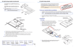
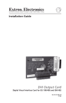
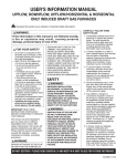
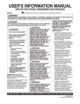
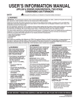
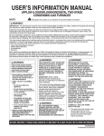
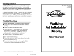
FF 120T
Flat Field Speaker
User’s Manual
1
5
Power down
Power down all attached devices before proceeding.
Suspended ceiling installation
Remove the ceiling tile where the FF 120T speaker will be
installed. Cut out a 12" section of the tile from either end
where the speaker will be installed, as shown below.
End Section
12”
Cut Material
2’
12”
2’
The transformer side of the CPX 120 cover plate has a
7-connector terminal block. Route the two wires from the
amplifier through the cover plate hole to the transformer side.
The black negative (-) wire attaches to the “COM” terminal,
and the red postitive (+) wire attaches to the desired terminal
tap.
100 V 70 V
2
Connecting wires to the CPX 120
terminal block
COM 16 W
COM
NC
8W
4W
2W
1W
NC
16 W
8W
4W
2W
1W
4’
or
From Amp
or
To Second Speaker
Cable Clamp
Adapter (supplied)
Seismic Anchor
Ring
Top Terminal
Cover
Locking Ring
See the NOTES below.
N Installation of conduit and conduit adapters should
conform to all applicable building codes and local
ordinances.
68-1450-02 Rev. A
07 09
C
N
W
W
1
1
W
W
2
8
C
O
M
N
C
C
O
M
16
16
Flexible Conduit
Adapter
V
Flexible
Conduit
70
The CPX 120 cover plates mount to the speakers with
the transformer side down. See the illustration below.
0V
Routing cables through the
CPX 120 cover plate
10
4
W
W
8
W
W
Loosen the two screws (do not remove) on the top terminal
cover plate and remove the cover plate.
• If a 70 V/100 V line distribution amplifier is being used,
such as the Extron XPA 2001-70V or XPA 2001-100V, the
cover plate is no longer needed since the included CPX 120
transformer cover plate will be installed in its place.
• If the 70 V/100 V line distribution system is not being
installed, retain the cover plate and proceed to step 6b.
2
Remove the terminal cover plate
W
3
24” x 24” Ceiling Tile
4
24” x 48” Ceiling Tile
Pull the speaker wires from the conduit if a conduit is used.
Strip 3/16" (5 mm) from the wire ends, keep the wire end
strands together by twisting them (do not tin the wires), and
secure the wires to the appropriate taps on the terminal
block’s captive screw connectors as indicated on the tap
label. Use a small flat blade screwdriver to tighten the
terminal block screws. See the note below for wiring
additional speakers.
W
Draw Lines
N Installation in a plenum-rated environment
requires a wire gauge of 12 AWG to 18 AWG.
4
2’
N Route the speaker wires from the second speaker
through the cover plate hole to the transformer
side and twist the black negative (-) wires together
and twist the red positive (+) wires together before
inserting them into the terminal block. Additional
speakers can be daisy chained this way.
N Be sure to observe the 70 V or 100 V system
designation as indicated on the label.
N Wiring two speakers in parallel requires that the
maximum wire gauge not exceed 16 AWG. In a
single speaker installation the wire gauge should
not exceed 12 AWG.
When using flexible conduit, insert the conduit into the cover
plate opening using an appropriate conduit adapter and
secure the conduit to the plate as shown in the following
illustration.
1
FF 120T
Flat Field Speaker
User’s Manual
6b
(Black) To Speaker
(-) Terminal
C
O
M
C
O
N
C
M
16
16
W
W
8
8
W
W
4
4
W
W
2
2
W
W
1
1
W
W
N
C
(Red) To Speaker
(+) Terminal
0V
70
V
10
To Second
Speaker
Black (-)
Red (+)
Black (-)
Red (+)
From Amplifier
(70V/100V)
When using plenum speaker wire without a conduit, insert
the wire through the cable clamp adapter (included) and
secure the adapter to the cover plate.
• If a seismic support line is being used, install the seismic
anchor ring (included) between the conduit adapter and
the CPX 120 cover plate as shown below.
• If the CPX 120 transformer cover plate is being installed,
proceed to step 6a, otherwise proceed to step 6b.
Connecting wires from a low
impedance amplifier to the
speaker
Route the wires from the amplifier to the speaker using the
same procedure for routing speaker wire (and conduit if
applicable) through the cover plate as described in step 3.
Strip 3/16" (5 mm) from the ends of the two speaker wire
leads (+ and -) coming from the amplifier. Keep the
wire strands together by twisting them (do not tin the wires),
and secure the wires to the speaker’s input terminals while
observing the correct polarity.
Connect the red positive (+) wire to the + speaker terminal
and connect the black negative (-) wire to the - speaker
terminal depending on whether one or two speakers are
being connected, as shown below.
Red Wire
To Amplifier
Black Wire
One Speaker
6a
Connecting wires from the
CPX 120 to the speaker
Strip 3/16" (5 mm) from the ends of the two speaker wire
leads (+ and -) coming from the transformer. Keep the
wire strands together by twisting them (do not tin the wires),
and secure the wires to the speaker’s input terminals while
observing the correct polarity.
Connect the red positive (+) wire to the + speaker terminal
and connect the black negative (-) wire to the - speaker
terminal as shown below. Proceed to step 7.
Red Wire
To Amplifier
To Second Speaker
To Amplifier
To Second Speaker
Black Wire
Two Speakers
Seismic Anchor Ring
Red Wire
To CPX 120 transformer
cover plate
Black Wire
2
FF 120T
Flat Field Speaker
User’s Manual
7
Installing the speaker in the
ceiling
Route the cable through
the seismic anchor ring
and bendout tab.
See the following illustration.
Anchor this end to a
suitable secure point.
a. Replace the cover plate and tighten the two cover
screws.
b. Install the included T-rail crosspiece into the ceiling
opening up against the cut tile.
c. Set the speaker into place so that the edges are
hidden by the support rails.
Bend Up Tab
Seismic
Safety
Cable
Repeated bending of the tab
may cause it to break off.
T-rail (1)
9
Power up
After checking all speaker connections, power up the
amplifier.
8
Attaching the seismic support
lines
If seismic support lines are being used, connect a line
through the seismic anchor ring on the top terminal cover
plate and attach it to one of the center seismic bendout tabs
(the center tab is preferred) located on either side the speaker
as shown below. Use a small screwdriver or similar tool to
bend out the tab. See the following illustration.
N Observe all applicable building codes and
local ordinances when installing the speaker.
3
FF 120T
Flat Field Speaker
User’s Manual
Application diagram
Specifications
Extron
FF 120T
Left
Audio/acoustic and electrical
Plenum Flat Field
Ceiling Speakers
DVD Player
Right
Speaker type................................. 1-way full-range in-ceiling speaker
Frequency range........................... 68 Hz to 18 kHz, -10 dB, half space
Power capacity.............................. 16 W rms continuous pink noise
32 W rms continuous program
Nominal sensitivity........................ 86 dB SPL, 1 watt, 1 m, half space
Nominal coverage angle............... 170° conical coverage
Nominal impedance ..................... 8 ohms per speaker
Driver............................................ (1) 3" (76.2 mm) paper cone
Input connector.............................. (1) 8 mm Euro-style captive screw terminal
block, 7 pole
Tap settings
70 V input.......................... 16 W, 8 W, 4 W, 2 W, 1 W, null (bypass 8 ohms
direct connection)
100 V input......................... Null,16 W, 8 W, 4 W, 2 W, 1 W (bypass 8 ohms
direct connection)
V
1-70
G
RIN
WI ND
S 2 OU
AS GR T S!
CL NOT OR UT
SH TP
DO OR OU
R
KE
mA
EA
50
SP
E
UT
V
10
L/M
VO
US
®
TED
LIS T O
17T IDE
IO/V TUS
AUD ARA
APP
TS
INPU
O)
40
MPA
UT
TP
OU
70V
E
ON
MOT
(M
RE
L
O)
R
Extron
MPA 401-70V
ON
L (M
WER
PO
R
V X
12 MA
3A
IN
IN
Extron
MIX 301
Three Channel
Mixer
12Va
0.5
Mini Power Amplifier
1
1
L
X 30NE
T
MI
AN
R
3 CH
XE
MI
3
IN
2
X OU
MI
X
MA
General
TE
MU
ME
LU
VO
P
M
0 AA
10
VC
Package ....................................... 2 speakers (1 pair) with 2' (61 cm) cross bars
Temperature/humidity.................... Storage: -40 to +158 °F (-40 to +70 °C) /
10% to 90%, noncondensing
Operating: +32 to +122 °F (0 to +50 °C) /
10% to 90%, noncondensing
Mounting....................................... Drops into 2' x 2' (61 cm x 61 cm) or 2' x 4'
(61 cm x 122 cm) suspended tile ceilings
Enclosure type .............................. Composite, rectangular, with metal grille
Enclosure outer dimensions........... 3.25" H x 23.75" W x 11.75" D
(8.3 cm H x 60.3 cm W x 29.9 cm D)
Product weight.............................. Single: 5.1 lbs (2.3 kg)
Shipping weight............................. Pair: 17 lbs (8 kg) with mounting kit
Vibration........................................ ISTA 1A in carton (International Safe Transit
Association)
Regulatory compliance
Safety ................................ NFPA90A, NFPA70;
UL Listed for use in plenum airspaces meets
UL 2043 for heat and smoke release, meets
UL 1480 for commercial and professional audio
systems
Warranty ....................................... 5 years parts and labor
Extron
VCM 100 AAP
Wireless
Microphone System
Volume/Mute Controller
in AAP 100 Frame
Packaging
FF 120T Setup
Guide
CPX 120 Transformer
Cover Plates (2)
Top Cap
All nominal levels are at ±10%.
Specifications are subject to change without notice.
Speakers
Cable Clamp-anchor
Ring Adapters
FF 120
Kit
Protective Bubble
Sheet
End Cap
Bottom Cap
Insta
Part
No.
ll 206W
XXX-X
Ceilin
XX-01
g Spea
33-XXXX01
ker
REV.
FF 120T
Master
Carton
Extron USA - West
Headquarters
+800.633.9876
Inside USA / Canada Only
www.extron.com
+1.714.491.1500
+1.714.491.1517 FAX
Extron USA - East
Extron Europe
Extron Asia
Extron Japan
Extron China
Extron Middle East
+800.633.9876
+800.3987.6673
+800.7339.8766
+81.3.3511.7655
+81.3.3511.7656 FAX
+400.883.1568
+971.4.2991800
+971.4.2991880 FAX
+1.919.863.1794
+1.919.863.1797 FAX
+31.33.453.4040
+31.33.453.4050 FAX
+65.6383.4400
+65.6383.4664 FAX
Inside USA / Canada Only
Inside Europe Only
Inside Asia Only
Inside China Only
+86.21.3760.1568
+86.21.3760.1566 FAX
4