1
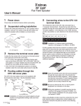
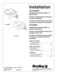
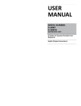
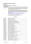
FF 220T Setup Guide
FF 220T Setup Guide (Continued)
For installations in a 2’ x 4’ ceiling tile (which was cut in
half in step 2), install the supplied T-rail crosspiece as shown
on the right.
Set the speaker in place in the ceiling and position it so
that the speaker edges are hidden by the support rails or
T-rails.
13. If seismic support lines are being used, install them.
See the illustration below.
NOTE:
This setup guide contains installation information about the Extron®
FF 220T Flat Field® speaker. This speaker is designed for use in plenum
rated ceiling spaces and can be dropped into a standard 2' x 2' or
2' x 4' (with supplied cross bars) false ceiling tile space on a T-bar grid.
Extron
FF 220T
CAUTION: Installation and service must be performed by authorized
Two-way Ceiling
Speakers
personnel only.
Observe all applicable building codes and local
ordinances when installing the speaker.
Factors to Consider Before Installation
Ceiling Tile
zz Installation of conduit and conduit adapters must conform to all applicable building codes and local ordinances.
zz Installation in a plenum-rated environment requires a wire gauge of 12 AWG to 18 AWG. Conduit may be required.
Existing
Ceiling Tile
Rails
NOTE:
T-rail
Crosspiece
(supplied)
If daisy chaining speakers in 70 V or 100 V configuration, maximum wire gauge is 16 AWG.
If daisy chaining speakers in direct (8 ohm) configuration, maximum wire gauge is 14 AWG.
zz If using seismic supports, the installer provides the cables.
zz Wiring connections depend on whether or not a distributed (70 or 100 volt) audio system is installed with these
speakers.
Anchor this end to a
suitable secure point.
Loosen, but do not remove
the 2 transformer cover plate
screws in the 2 keyhole slots.
Installation
Route the seismic line
through the line retainer
and bendout tab.
Initial Steps
1. Power down all attached devices before proceeding.
Transformer Cover Plate
2. Remove the 2' x 2' ceiling tile where the FF 220T will be
installed. If the ceiling has 2' x 4' tiles, cut the tile in half.
3. Loosen, but do not remove, the two screws on the top
terminal cover plate as shown on right.
4. Slide and remove the terminal cover plate, which is
installed with the transformer side down. See below.
Seismic
Safety
Cable
Bend Up Tab
Repeated bending
of the tab may cause it
to break off.
(Black) To Speaker - Terminal
(Red) To Speaker + Terminal
a. Temporarily remove a ceiling tile adjacent to the speaker and set it aside.
W
W
4
4
W
8
W
8
W
W
16
16
C
O
M
C
N
O
C
M
c. Attach the other end of the cable to a sturdy part of the building (studs, roof struts, and the like).
2
2
W
W
1
1
W
W
N
C
b. Connect a seismic support cable through the cable pass through loop, and attach it to one of the seismic
bendout tabs located on either side of the speaker.
0V
70
V
10
d. For additional support lines repeat as needed. Refer to the FF 220T User Guide for further details.
To Second
Speaker
e. Replace the ceiling tile removed in step 13a.
14. Check all wiring before powering up the amplifier.
Black (-)
Red (+)
Black (-)
Red (+)
From Amplifier
(70V/100V)
Extron USA - West
Extron USA - East
Extron Europe
Extron Asia
Extron Japan
Extron China
Extron Middle East
+800.633.9876
Inside USA/Canada
Only
+800.633.9876
Inside USA/Canada
Only
+800.3987.6673
Inside Europe Only
+800.7339.8766
Inside Asia Only
+81.3.3511.7655
+81.3.3511.7656 FAX
+400.833.1568
Inside China Only
+971.4.2991800
+971.4.2991880 FAX
+1.714.491.1500
+1.714.491.1517 FAX
+1.919.863.1794
+1.919.863.1797 FAX
+31.33.453.4040
+31.33.453.4050 FAX
+65.6383.4400
+65.6383.4664 FAX
Headquarters
+86.21.3760.1568
+86.21.3760.1566 FAX
© 2010 Extron Electronics. All Rights Reserved. www.extron.com
5. When using flexible conduit, insert the conduit into the cover plate
opening using an appropriate conduit adapter and secure the
conduit to the plate. See right.
Flexible Conduit Adapter
Flexible Conduit
Transformer Cover Plate
Seismic Cable Pass
Through Loop
Rear of Speaker
68-1683-50
Rev. A
09 10
4
1
FF 220T Setup Guide (Continued)
When using speaker wires without a conduit, secure the
cable clamp adapter (included) to the cover plate and insert the
wires through the clamp. See right.
8. Connect wires from the transformer to the speaker.
Cable Clamp
Adapter
a. Keep the wire strands together by twisting them (do not tin
the wires).
6. Proceed to steps 7 or 9 for the appropriate wiring instructions
either for a distributed audio system (70 V or 100 V line
distribution through the transformer) or for a direct connection
from an amplifier (bypassing the transformer).
b. Connect the red positive (+) wire to the + speaker terminal and connect the black negative (-) wire to the - speaker
terminal as shown below.
Transformer Cover Plate
Transformer Cover Plate
NOTE:
In the 70 V or 100 V distribution system block
diagram below, an optional speaker has been added
as an example of daisy chaining FF 220T speakers to a
single amplifier output.
Seismic Cable Pass
Through Loop
Red Wire
Rear of Speaker
To transformer
Black Wire
Rear of Speaker
Installation in a 70 V or 100 V Audio Distribution System (through the transformer)
7. Connect cables from the amplifier to the
transformer on the FF 220T terminal cover plate.
a. Pull the wires from the amplifier through and
out of the conduit, if a conduit is used.
Additional
FF 220T
Speaker(s)
b. Route the two wires from the amplifier
through the cover plate hole to the transformer
side.
c. Strip 3/16" (5 mm) from the wire ends and keep
the wire end strands together by twisting them.
Do not tin the wires.
c. Proceed to step 10.
Transformer
Plate
Transformer
Plate
Installation with Direct 8 ohm Connection to an Amplifier (bypassing the transformer)
Amplifier
70 V or 100 V Distribution System
(through the transformer)
An additional FF 220T
can be attached to
to the tap connector.
See step 7 below.
FF 220T
a. Route the wires from the amplifier to the speaker using the same
procedure for routing speaker wire (and conduit if applicable) through
the cover plate as described in step 5. Strip 3/16 inch (5 mm) from the
ends of the 2 speaker wire leads (+ and -) coming from the amplifier.
Keep the wire strands together by twisting them (do not tin the wires),
and secure the wires to the input terminals of the speaker while
observing the correct polarity.
Transformer
Plate
FF 220T
Amplifier
Direct 8 ohm Connection
(bypassing the transformer)
b. Connect the red positive (+) wire to the + speaker terminal and connect
the black negative (-) wire to the - speaker terminal depending on
whether one or two speakers are being connected as shown below.
Red Wire
From Amplifier (+)
4W
2W
1W
NC
COM
16 W
8W
4W
2W
1W
2
2
W
W
4
4
W
W
8
8
W
W
16
16
M
O
C
N
C
M
O
C
V
8W
70
COM 16 W
Red Wire
From Amplifier
To Second Speaker
From Amplifier
To Second Speaker
Black Wire
Red Wire
From Amplifier
Black Wire
0V
100 V 70 V
Observe the 70 V or 100 V system
designation as indicated on the tap label.
10
NOTE:
W
W
1
1
W
W
N
C
d. Secure the wires to the appropriate taps on the
captive screw connectors of the 7-connector
terminal block (on the transformer side of the
cover plate) as indicated on the tap label. See the note
below. The black, negative (-) wire attaches to the “COM”
terminal, and the red, positive (+) wire attaches to the
desired terminal tap. See the diagram at right.
FF 220T
9. See the block diagram on the right.
Black Wire
From Amplifier (-)
NC
Wiring to a Single Speaker
e. Use a small flat blade screwdriver to tighten the terminal
block screws.
Finishing Steps, All Installation Types
W
W
2
2
W
W
4
4
W
W
M
N
C
C
O
M
16
16
W
8
8
W
Red Wires
1
1
W
W
N
C
10. Replace the transformer cover plate and tighten the two
cover plate screws that were loosened in step 3.
O
C
0V
70
V
10
f. To wire additional speakers, route speaker wires from the
second speaker through the cover plate hole to the
transformer side, and twist the black negative (-) wires together
and twist the red positive (+) wires together before inserting
them into the terminal block. Additional speakers can be daisy
chained this way. See the diagram at right.
Two Speakers
One Speaker
Black Wires
From Amplifier (+)
To Next Speaker (tap)
From Amplifier (-)
To Next Speaker (com)
Wiring to Multiple Speakers
11. Temporarily test the system and speakers by powering on
the amplifier and listening for the correct response from
the speakers, then disconnect power from the amplifier.
Extron
FF 220T
Two-way Ceiling
Speakers
12. For installation in a 2’ x 2’ ceiling tile, remove a tile and
place the speaker on the existing support rails as shown
on the right.
Ceiling Tile
Ceiling Tile
Rails
2
3
FF 220T Setup Guide
FF 220T Setup Guide (Continued)
For installations in a 2’ x 4’ ceiling tile (which was cut in
half in step 2), install the supplied T-rail crosspiece as shown
on the right.
Set the speaker in place in the ceiling and position it so
that the speaker edges are hidden by the support rails or
T-rails.
13. If seismic support lines are being used, install them.
See the illustration below.
NOTE:
This setup guide contains installation information about the Extron®
FF 220T Flat Field® speaker. This speaker is designed for use in plenum
rated ceiling spaces and can be dropped into a standard 2' x 2' or
2' x 4' (with supplied cross bars) false ceiling tile space on a T-bar grid.
Extron
FF 220T
CAUTION: Installation and service must be performed by authorized
Two-way Ceiling
Speakers
personnel only.
Observe all applicable building codes and local
ordinances when installing the speaker.
Factors to Consider Before Installation
Ceiling Tile
zz Installation of conduit and conduit adapters must conform to all applicable building codes and local ordinances.
zz Installation in a plenum-rated environment requires a wire gauge of 12 AWG to 18 AWG. Conduit may be required.
Existing
Ceiling Tile
Rails
NOTE:
T-rail
Crosspiece
(supplied)
If daisy chaining speakers in 70 V or 100 V configuration, maximum wire gauge is 16 AWG.
If daisy chaining speakers in direct (8 ohm) configuration, maximum wire gauge is 14 AWG.
zz If using seismic supports, the installer provides the cables.
zz Wiring connections depend on whether or not a distributed (70 or 100 volt) audio system is installed with these
speakers.
Anchor this end to a
suitable secure point.
Loosen, but do not remove
the 2 transformer cover plate
screws in the 2 keyhole slots.
Installation
Route the seismic line
through the line retainer
and bendout tab.
Initial Steps
1. Power down all attached devices before proceeding.
Transformer Cover Plate
2. Remove the 2' x 2' ceiling tile where the FF 220T will be
installed. If the ceiling has 2' x 4' tiles, cut the tile in half.
3. Loosen, but do not remove, the two screws on the top
terminal cover plate as shown on right.
4. Slide and remove the terminal cover plate, which is
installed with the transformer side down. See below.
Seismic
Safety
Cable
Bend Up Tab
Repeated bending
of the tab may cause it
to break off.
(Black) To Speaker - Terminal
(Red) To Speaker + Terminal
a. Temporarily remove a ceiling tile adjacent to the speaker and set it aside.
W
W
4
4
W
8
W
8
W
W
16
16
C
O
M
C
N
O
C
M
c. Attach the other end of the cable to a sturdy part of the building (studs, roof struts, and the like).
2
2
W
W
1
1
W
W
N
C
b. Connect a seismic support cable through the cable pass through loop, and attach it to one of the seismic
bendout tabs located on either side of the speaker.
0V
70
V
10
d. For additional support lines repeat as needed. Refer to the FF 220T User Guide for further details.
To Second
Speaker
e. Replace the ceiling tile removed in step 13a.
14. Check all wiring before powering up the amplifier.
Black (-)
Red (+)
Black (-)
Red (+)
From Amplifier
(70V/100V)
Extron USA - West
Extron USA - East
Extron Europe
Extron Asia
Extron Japan
Extron China
Extron Middle East
+800.633.9876
Inside USA/Canada
Only
+800.633.9876
Inside USA/Canada
Only
+800.3987.6673
Inside Europe Only
+800.7339.8766
Inside Asia Only
+81.3.3511.7655
+81.3.3511.7656 FAX
+400.833.1568
Inside China Only
+971.4.2991800
+971.4.2991880 FAX
+1.714.491.1500
+1.714.491.1517 FAX
+1.919.863.1794
+1.919.863.1797 FAX
+31.33.453.4040
+31.33.453.4050 FAX
+65.6383.4400
+65.6383.4664 FAX
Headquarters
+86.21.3760.1568
+86.21.3760.1566 FAX
© 2010 Extron Electronics. All Rights Reserved. www.extron.com
5. When using flexible conduit, insert the conduit into the cover plate
opening using an appropriate conduit adapter and secure the
conduit to the plate. See right.
Flexible Conduit Adapter
Flexible Conduit
Transformer Cover Plate
Seismic Cable Pass
Through Loop
Rear of Speaker
68-1683-50
Rev. A
09 10
4
1