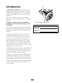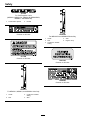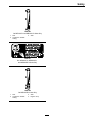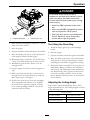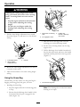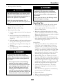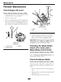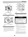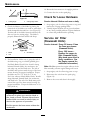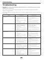
1
METRO 21
®
For Serial Nos.
790,000 & Higher
Part No. 4500-400 Rev. A
WARNING
CALIFORNIA
Proposition 65 Warning
The engine exhaust from this product
contains chemicals known to the State of
California to cause cancer, birth defects, or
other reproductive harm.
Important: When the mower is used or operated
on any California forest, brush or grass covered
land, a working spark arrester must be attached
to the muffler. If not, the operator is violating
state law, Section 4442 Public Resource Code. To
acquire a spark arrester for your unit, see your
Engine Service Dealer.
This spark ignition system complies with Canadian
ICES-002 Ce système d’allumage par ètincelle de
vèhicule est conforme à la norme NMB-002 du
Canada
The enclosed Engine Owner’s Manual is
supplied for information regarding The U.S.
Environmental Protection Agency (EPA) and
the California Emission Control Regulation of
emission systems, maintenance and warranty.
Keep this engine Owner’s Manual with your unit.
Should this engine Owner’s Manual become
damaged or illegible, replace immediately.
Replacements may be ordered through the
engine manufacturer.
Exmark reserves the right to make changes or
add improvements to its products at any time
without incurring any obligation to make such
changes to products manufactured previously.
Exmark, or its distributors and dealers, accept
no responsibility for variations which may be
evident in the actual specifications of its products
and the statements and descriptions contained
in this publication.
© 2008—Exmark Mfg. Co., Inc.
Industrial Park Box 808
Beatrice, NE 68310
2
Contact us at www.Exmark.com.
Printed in the USA
All Rights Reserved
Introduction
CONGRATULATIONS on the purchase of your
Exmark Mower. This product has been carefully
designed and manufactured to give you a maximum
amount of dependability and years of trouble-free
operation.
This manual contains operating, maintenance,
adjustment, and safety instructions for your Exmark
mower.
Figure 1
BEFORE OPERATING YOUR MOWER,
CAREFULLY READ THIS MANUAL IN ITS
ENTIRETY.
1. Model and serial number location
By following the operating, maintenance, and safety
instructions, you will prolong the life of your mower,
maintain its maximum efficiency, and promote safe
operation.
Model No.
Serial No.
If additional information is needed, or should you
require trained mechanic service, contact your
authorized Exmark equipment dealer or distributor.
All Exmark equipment dealers and distributors are
kept informed of the latest methods of servicing
and are equipped to provide prompt and efficient
service in the field or at their service stations. They
carry ample stock of service parts or can secure them
promptly for you from the factory.
All Exmark parts are thoroughly tested and inspected
before leaving the factory, however, attention is
required on your part if you are to obtain the fullest
measure of satisfaction and performance.
Whenever you need service, genuine Exmark parts,
or additional information, contact an Authorized
Service Dealer or Exmark Customer Service and have
the model and serial numbers of your product ready.
Figure 1 identifies the location of the model and serial
numbers on the product. Write the numbers in the
space provided.
3
Contents
Emptying the Fuel Tank and Cleaning
the Fuel Filter (Kawasaki Units
Only)......................................................... 34
Waste Disposal .............................................. 34
Storage ................................................................. 35
Preparing the Fuel System.............................. 35
Preparing the Engine ..................................... 35
General Storage Information ......................... 35
Removing the Lawn Mower from
Storage...................................................... 35
Troubleshooting ................................................... 36
Introduction ........................................................... 3
Safety ..................................................................... 5
Safety Alert Symbol ......................................... 5
Safe Operating Practices .................................. 5
Safety and Instructional Decals ....................... 9
Specifications ....................................................... 12
Model Numbers ............................................ 12
Systems ......................................................... 12
Dimensions................................................... 12
Product Overview ................................................ 13
Operation ............................................................. 14
Controls ........................................................ 14
Pre-Start........................................................ 15
Operating Instructions .................................. 16
Maintenance ......................................................... 23
Recommended Maintenance Schedule(s) ........... 23
Periodic Maintenance ....................................... 24
Check Engine Oil Level ................................. 24
Checking the Blade Brake Clutch (For
Units with a Blade Brake Clutch
Only)......................................................... 24
Check the Mower Blade ................................. 24
Check for Loose Hardware ............................ 26
Service Air Filter(Kawasaki Units) ................. 26
Service Air Filter(Honda Units) ..................... 27
Change Engine Oil ........................................ 28
Changing the Oil Filter (Kawasaki Units
Only):........................................................ 28
Servicing the Wheels ..................................... 29
Check Condition Of Belt(Self-Propelled
Units Only) ............................................... 29
Lubricate the Pivot Arms............................... 29
Lubricate the Gear Case(Self-Propelled
Units Only) ............................................... 30
Check Spark Plugs ......................................... 30
Adjustments ..................................................... 31
Adjusting the Self-Propel
Drive(Self-Propelled Units Only) ............... 31
Adjusting the Blade Brake Cable .................... 31
Cleaning ........................................................... 32
Clean Grass Build-Up Under Deck ................ 32
Cleaning the Discharge Tunnel and
Plug........................................................... 32
Cleaning Under the Belt
Cover(Self-Propelled Models Only) ........... 33
Cleaning the Blade Brake Clutch
Shield ........................................................ 33
4
Safety
Safety
Safe Operating Practices
Safety Alert Symbol
Training
This lawn mower meets or exceeds the CPSC blade
safety requirements for walk-behind rotary mowers
and the B71.4 specifications of the American National
Standards Institute in effect at the time of production
• Read the Operator’s Manual and other training
material. If the operator(s) or mechanic(s) can
not read English it is the owner’s responsibility to
explain this material to them.
• Become familiar with the safe operation of the
equipment, operator controls, and safety signs.
Exmark designed and tested this lawn mower to offer
reasonably safe service; however, failure to comply
with the following instructions may result in personal
injury.
• All operators and mechanics should be trained.
The owner is responsible for training the users.
• Never let children or untrained people operate
or service the equipment. Local regulations may
restrict the age of the operator.
This Safety Alert Symbol (Figure 2) is used both in
this manual and on the machine to identify important
safety messages which must be followed to avoid
accidents
• The owner/user can prevent and is responsible
for accidents or injuries occurring to himself or
herself, other people or property.
This symbol means: ATTENTION! BECOME
ALERT! YOUR SAFETY IS INVOLVED!
Preparation
• Evaluate the terrain to determine what accessories
and attachments are needed to properly and
safely perform the job. Only use accessories and
attachments approved by Exmark.
Figure 2
1. Safety alert symbol
• Wear appropriate clothing including safety glasses,
substantial footwear, long trousers, and hearing
protection. Do Not operate when barefoot or
when wearing open sandals. Long hair, loose
clothing or jewelry may get tangled in moving
parts.
The safety alert symbol appears above information
which alerts you to unsafe actions or situations
and will be followed by the word DANGER,
WARNING, or CAUTION.
DANGER: White lettering / Red background.
Indicates an imminently hazardous situation which, if
not avoided, Will result in death or serious injury.
CAUTION
WARNING: Black lettering / Orange background.
Indicates a potentially hazardous situation which, if
not avoided, Could result in death or serious injury.
This machine produces sound levels in
excess of 85 dBA at the operator’s ear and
can cause hearing loss through extended
periods of exposure.
CAUTION: Black lettering / Yellow background.
Indicates a potentially hazardous situation which, if
not avoided, May result in minor or moderate injury.
Wear hearing protection when operating this
machine.
This manual uses two other words to highlight
information. Important calls attention to special
mechanical information and Note emphasizes
general information worthy of special attention.
• Inspect the area where the equipment is to be
used and remove all rocks, toys, sticks, wires,
bones, and other foreign objects which can be
thrown by the machine and may cause personal
injury to the operator or bystanders.
5
Safety
DANGER
DANGER
In certain conditions gasoline is extremely
flammable and vapors are explosive.
A fire or explosion from gasoline can burn
you, others, and cause property damage.
In certain conditions during fueling, static
electricity can be released causing a spark
which can ignite gasoline vapors. A fire or
explosion from gasoline can burn you and
others and cause property damage.
• Fill the fuel tank outdoors in an open
area, when the engine is cold. Wipe up
any gasoline that spills.
• Always place gasoline containers on the
ground away from your vehicle before
filling.
• Never refill the fuel tank or drain the
machine indoors or inside an enclosed
trailer.
• Do Not fill gasoline containers inside a
vehicle or on a truck or trailer bed because
interior carpets or plastic truck bed liners
may insulate the container and slow the
loss of any static charge.
• Do Not fill the fuel tank completely
full. Add gasoline to the fuel tank until
the level is 1/4 to 1/2 inch (6–13 mm)
below the bottom of the filler neck. This
empty space in the tank allows gasoline
to expand.
• When practical, remove gas-powered
equipment from the truck or trailer and
refuel the equipment with its wheels on
the ground.
• Never smoke when handling gasoline,
and stay away from an open flame or
where gasoline fumes may be ignited by
spark.
• If this is not possible, then refuel such
equipment on a truck or trailer from a
portable container, rather than from a
gasoline dispenser nozzle.
• Store gasoline in an approved container
and keep it out of the reach of children.
• If a gasoline dispenser nozzle must be
used, keep the nozzle in contact with the
rim of the fuel tank or container opening
at all times until fueling is complete.
• Add fuel before starting the engine.
Never remove the cap of the fuel tank or
add fuel when engine is running or when
the engine is hot.
WARNING
• If fuel is spilled, Do Not attempt to start
the engine. Move away from the area of
the spill and avoid creating any source of
ignition until fuel vapors have dissipated.
Gasoline is harmful or fatal if swallowed.
Long-term exposure to vapors has caused
cancer in laboratory animals. Failure to use
caution may cause serious injury or illness.
• Do Not operate without entire exhaust
system in place and in proper working
condition.
• Avoid prolonged breathing of vapors.
• Keep face away from nozzle and gas
tank/container opening.
• Keep away from eyes and skin.
• Never siphon by mouth.
• Check that the operator’s presence controls,
safety switches, and shields are attached and
functioning properly. Do Not operate unless they
are functioning properly.
6
Safety
Operation
• Never attempt to make wheel height adjustments
while the engine is running.
WARNING
• Stop engine, wait for all moving parts to stop,
remove the spark plug wire(s) and/or remove key.
Operating engine parts, especially the
muffler, become extremely hot. Severe burns
can occur on contact and debris, such as
leaves, grass, brush, etc. can catch fire.
– Before checking, cleaning or working on the
mower.
– After striking a foreign object or abnormal
vibration occurs (inspect the mower for
damage and make repairs before restarting
and operating the mower).
• Allow engine parts, especially the muffler,
to cool before touching.
• Remove accumulated debris from muffler
and engine area.
– Before clearing blockages.
– Whenever you leave the mower.
• Install and maintain in working order a
spark arrester before using equipment
on forest-covered, grass-covered, or
brush-covered unimproved land.
• Stop engine, wait for all moving parts to stop:
– Before refueling.
– Before dumping the grass catcher.
– Before making height adjustments.
WARNING
WARNING
Engine exhaust contains carbon monoxide,
which is an odorless deadly poison that can
kill you.
Hands, feet, hair, clothing, or accessories can
become entangled in rotating parts. Contact
with the rotating parts can cause traumatic
amputation or severe lacerations.
Do Not run engine indoors or in a small
confined area where dangerous carbon
monoxide fumes can collect.
• Do Not operate the machine without
guards, shields, and safety devices in
place and working properly.
• Operate only in daylight or good artificial light,
keeping away from holes and hidden hazards.
• Start the engine carefully according to instructions
with feet well away from the blades.
• Never raise deck with blades running.
• Never operate the mower with damaged guards,
shields, or covers. Always have safety shields,
guards, switches and other devices in place and in
proper working condition.
• Never mow with the discharge deflector raised,
removed or altered unless there is a grass
collection system or mulch kit in place and
working properly.
• Grass catcher components are subject to wear,
damage and deterioration, which could expose
moving parts or allow objects to be thrown.
Frequently check the components and replace
them with the manufacturer’s recommended parts
when necessary.
• Do Not change the engine governor setting or
overspeed the engine.
• Keep hands, feet, hair, jewelry, or clothing
away from rotating parts.
• Keep clear of the discharge opening at all times.
• To extend the life the engine brake, place the
throttle control in the “slow” position; then stop
the engine.
• This mower was designed for one operator
only. Keep all others away from mower during
operation.
• DO NOT operate the mower when people,
especially children, or pets are in the area.
• Be alert, slow down and use caution when making
turns. Look behind and to the side before
changing directions.
• Stop the blades, slow down, and use caution when
crossing surfaces other than grass and when
transporting the mower to and from the area to
be mowed.
7
Safety
Maintenance and Storage
• Be aware of the mower discharge path and direct
discharge away from others.
• Do Not operate the mower under the influence
of alcohol or drugs.
• Use extreme care when loading or unloading the
machine into a trailer or truck.
• Use care when approaching blind corners, shrubs,
trees, or other objects that may obscure vision.
• Stop the engine and remove the spark plug wire(s)
and/or remove key. Wait for all movement to
stop before adjusting, cleaning or repairing.
• Keep engine and engine area free from
accumulation of grass, leaves, excessive grease
or oil, and other debris which can accumulate
in these areas. These materials can become
combustible and may result in a fire.
Slope Operation
• Let engine cool before storing and Do Not store
near flame or any enclosed area where open pilot
lights or heat appliances are present.
Use Extreme caution when mowing and/or turning
on slopes as loss of traction and/or tip-over could
occur. The operator is responsible for safe operation
on slopes.
• Shut off fuel while storing or transporting. Do
Not store fuel near flames or drain indoors.
• Park machine on level ground. Never allow
untrained personnel to service machine.
DANGER
Operating on wet grass or steep slopes can
cause sliding and loss of control. Loss of
control and/or loss of operator’s footing
could result in a fall with an arm or leg
getting under the mower or engine deck
which may result in serious injury, death or
drowning.
• Remove spark plug wire before making any
repairs.
• Mow across slopes, never up and down.
• Keep hands and feet away from moving parts.
If possible, Do Not make adjustments with the
engine running.
• Use care when checking blades. Wrap the blade(s)
or wear gloves, and use caution when servicing
them. Only replace blades. Never straighten or
weld them.
• Do Not mow slopes when grass is wet.
• Do Not mow near drop-offs or near water.
• Do Not mow excessively steep slopes.
• Keep all guards, shields and all safety devices in
place and in safe working condition.
• Reduce speed and use extreme caution
on slopes.
• Check all bolts frequently to maintain proper
tightness.
• Avoid sudden turns or rapid speed
changes.
• Frequently check for worn or deteriorating
components that could create a hazard.
• All replacement parts must be the same as
or equivalent to the parts supplied as original
equipment.
• When feasible, avoid operating the equipment in
wet grass.
• Progressively greater care is needed as the slope
increases.
• Remove or mark obstacles such as rocks, tree
limbs, etc. from the mowing area. Tall grass can
hide obstacles.
• Watch for ditches, holes, rocks, dips and rises that
change the operating angle, as rough terrain could
overturn the machine.
• Use extreme care with grass catchers or
attachments. These can change the stability of the
machine and cause loss of control.
8
Safety
Safety and Instructional Decals
• Keep all safety signs legible. Remove all grease,
dirt and debris from safety signs and instructional
labels.
• Replace all worn, damaged, or missing safety
signs.
• When replacement components are installed, be
sure that current safety signs are affixed to the
replaced components.
• If an attachment or accessory has been installed,
make sure current safety signs are visible.
• New safety signs may be obtained from
your authorized Exmark equipment dealer or
distributor or from Exmark Mfg. Co. Inc.
• Safety signs may be affixed by peeling off the
backing to expose the adhesive surface. Apply
only to a clean, dry surface. Smooth to remove
any air bubbles.
• Familiarize yourself with the following safety signs
and instruction labels. They are critical to the safe
operation of your Exmark commercial mower.
52-2610
For Push Units
(MPKA21 and MPKA21CA)
39-5770
For Units without a Blade Brake Clutch
(MPKA21, MPKA21CA, MSKA21, MSKA21CA,
and MSHN21)
52-2620
For Self-Propelled Units
(MSKA21, MSKA21CA, MSKA21B, MSKA21BCA,
MSHN21, and MSHN21B)
68-7410
Common to All Units
43-8480
For Units with a Blade Brake Clutch
(MSKA21B, MSHN21B, and MSKA21BCA)
9
Safety
74-1970
For Self-Propelled Units
(MSKA21, MSKA21CA, MSKA21B, MSKA21BCA,
MSHN21, and MSHN21B)
1. Transmission speeds
2. Neutral
77-0500
Common to All Units
103-6328
For MSKA21B and MSHN21B Units Only
1. Choke
2. Fast
3. Continuous variable
setting
4. Slow
5. Engine—stop
93-7398
Common to All Units
104-1329
Common to All Units
104-8585
Common to All Units
103-6327
For MPKA21, MSKA21, and MSHN21 Units Only
1. Choke
2. Fast
3. Continuous variable
setting
4. Slow
10
Safety
109-8190
On MPKA21CA and MSKA21CA Units Only
1. Fast
2. Continuous variable
setting
3. Slow
109-8191
On MPKA21CA, MSKA21CA,
and MSKA21BCA Units Only
109-8194
On MSKA21BCA Units Only
1. Fast
2. Continuous variable
setting
3. Slow
4. Engine—stop
11
Specifications
Specifications
Model Numbers
Serial Nos: 790,000 and Higher
MPKA21; MPKA21CA; MSKA21; MSKA21CA; MSKA21B; MSKA21BCA; MSHN21; MSHN21B
Systems
Cutting Deck
• Cutting Width: 21 inches (53.3 cm)
Engine
• Blade Brake: When the blade engagement control
is moved to the disengaged position a friction
brake pad stops the rotation of the blades.
• Engine Specifications: See your Engine Owner’s
Manual
• RPM: 3300 (No Load)
• Blade Size: (1 ea.): 20.88 inches (53.0 cm)
• Deck: 21 inches rigid. Deck design allows for
bagging, mulching or side discharge.
Fuel System
• Capacity:
• Cutting Height Adjustment:
MPKA21, MSKA21, and MSKA21B Units:
4.0 qt (3.8 L)
Adjusts from 3/4 inches (1.9 cm) to 3 1/4 inches
(8.3 cm) in 1/2 inch (1.3 cm) increments.
MPKA21CA, MSKA21CA, and MSKA21BCA
Units: 2.1 qt (2.0 L)
• Mulching Kit: Standard
Honda Units: 2.1 qt (2.0 L)
• Side Discharge Kit: Optional
• Type of Fuel: Regular unleaded gasoline, 87
octane or higher.
• Fuel Filter: Non-replaceable, in tank
• Fuel Shut-Off Valve: MPKA21, MSKA21, and
MSKA21B and Honda Units: In-line 1/4 turn
increments.
Dimensions
Curb Weight:
122 lb (55 kg) Weights may vary slightly depending
on engine option.
MPKA21CA, MSKA21CA, and MSKA21BCA
Units Do Not have a shut-off valve.
Overall Width:
Safety Interlock System
22.25 inches (56.5 cm)
For units without a Blade Brake Clutch: Operator
must have the blade control bail depressed to start
the engine. Releasing the blade control bail will cause
the engine to stop.
Transmission (Self Propelled Units)
3 speeds forward
Speed Range:
• 1st–2.0 mph (3.2 km/hr)
• 2nd–2.9 mph (4.6 km/hr)
• 3rd–4.1 mph (6.6 km/hr)
12
Product Overview
Overall Length and Height at
2 1/4 inch Cutting Height:
Handle Setting
Length
Height
High
60.50 inches
(153.7 cm)
42.75 inches
(108.6 cm)
Medium
64.25 inches
(163.2 cm)
40.38 inches
(102.6 cm)
Low
67.00 inches
(170.2 cm)
37.88 inches
(96.2 cm)
Product Overview
Overall Length and Height at
Alternate Handle Mounting Position:
Handle Setting
Length
Height
High
62.63 inches
(159.1 cm)
37.50 inches
(95.3 cm)
Medium
64.38 inches
(163.5 cm)
35.50 inches
(90.2 cm)
66.25 inches
(168.3 cm)
33.63 inches
(85.4 cm)
Low
Figure 3
1. Spark plug
2.
3.
4.
5.
8. Drive Bail
(Self-Propelled Units
Only)
9. Throttle/Choke control
10. Fuel tank
11. Oil filter
12. Air filter
Oil fill/dipstick
Discharge door handle
Grass bag
Blade Control Lever
(Blade Brake Units Only)
6. Blade Control Bail
13. Cutting height lever
7. Handle
13
Operation
Operation
control lever. When this bail is released the unit will
stop moving.
Note: Determine the left and right sides of the
machine from the normal operating position.
Throttle-Choke Control
Controls
The throttle-choke control is located on the left side
of the handles as shown in Figure 4.
Blade Control Bail
The lever is used to control engine speed. Moving
the lever to the full forward (Choke) position will
place the lever in the choke position. The choke aids
in starting a cold engine. Moving the throttle control
forward will increase engine speed and moving it to
the rear will decrease engine speed.
Located on the upper handle as shown in Figure 4.
When the blade control bail is depressed, the system
senses that the operator is in the normal operator’s
position.
• For Units with a Blade Brake Clutch: When
the blade control bail is released, the system
senses that the operator has moved from the
normal operating position and will stop the blade.
• For Units without a Blade Brake Clutch:
When the blade control bail is released, the system
senses that the operator has moved from the
normal operating position and will kill the engine.
For units with a Blade Brake Control: The
throttle-choke control also includes an engine kill
position. Moving the lever into the full rearward
(Off) position will kill the engine.
Note: MPKA21CA, MSKA21CA, and
MSKA21BCA Units Do Not have a choke.
Blade Control Lever (Blade Brake
Clutch Units Only):
The blade control lever is located on the right side of
the handle next to the Blade Control Bail as shown
in Figure 4.
Moving the blade control lever into the full forward
position while depressing the blade control bail
engages the blade. Releasing the blade control bail
automatically disengages the blades.
Ground Speed (Shifter) Control
(Self-Propelled Units Only):
The ground speed control is located at the rear of the
belt cover as shown in Figure 5.
Figure 4
4. Handle
1. Throttle-Choke Control
5. Drive Bail
2. Blade Control Lever
(Self-Propelled Units
(Blade Brake Units Only)
Only)
3. Blade Control Bail
The ground speed control has three settings which
control the ground speed of the mower: 1 is slow, 2
is medium, and 3 is fast.
Self-Propel Drive Bail (For
Self-Propelled Units Only)
Located on the upper handle as shown in Figure 4.
When the self-propel drive bail is squeezed, the unit
will move forward at the speed set on the speed
14
Operation
Figure 5
1. Ground speed control
Figure 7
MSHN21 and MSHN21B Units
Fuel Shut-Off Valve
1. Fuel valve
For MPKA21, MSKA21, and MSKA21B Units:
The fuel shut off valve is installed on the fuel line
midway between the fuel tank and the engine as
shown in Figure 6.
For MPKA21CA, MSKA21CA, and MSKA21BCA
Units:Do not have a fuel shut off valve.
The fuel shut off valve shuts off the flow of fuel
when the machine will not be used for a few days,
when parking inside a building, and during transport
to and from the job. Rotate the valve 1/4 turn
clockwise to shut off fuel. Rotate the valve 1/4 turn
counterclockwise to turn on fuel.
Pre-Start
Fill fuel tank. For best results use only clean, fresh
regular grade unleaded gasoline with an octane rating
of 87 or higher. To ensure freshness, purchase only
the quantity of gasoline that you expect to use in
30 days. Using unleaded gasoline results in fewer
combustion deposits and longer engine life. See
Engine Owner’s Manual.
Figure 6
MPKA21, MSKA21, and MSKA21B Units
1. Fuel line
2. Fuel valve
3. Elbow fitting
Do Not add oil to gasoline.
For MSHN21 and MSHN21B Units: The fuel
shut off valve is located on the engine as shown in
Figure 7.
Do Not use methanol, gasoline containing methanol,
gasohol containing more the 10% ethanol, premium
gasoline or white gas. Using these fuels can damage
the engine’s fuel system.
Do Not use gasoline that has been stored since the
last mowing season or longer.
Do Not overfill fuel tank. Never fill the fuel tank so
that the fuel level rises above a level that is 1/2 inch
below the bottom of the filler neck to allow for fuel
expansion and prevent fuel spillage.
15
Operation
Make sure you understand the controls, their
locations, their functions, and their safety
requirements.
1. Install the hardware in the lower holes in the
handle and latches as shown in Figure 8.
2. Install hardware in one of the three adjustment
holes in the upper ends of each of the handle
latches to obtain the desired handle height within
the selected range.
Refer to the Maintenance section and perform all the
necessary inspection and maintenance steps.
Operating Instructions
3. Slide the bag support rod through into the upper,
middle, or lower mounting holes in the handle
and secure each end with a cap locknut. The bag
support rod mounting hole location corresponds
with the mounting hole location for the handle
latches as shown in the table.
Handle Adjustment
The handle may be adjusted to different heights for
comfortable operation. Stand behind the handle to
determine the height. to adjust the handle height,
position the capscrews and the locknuts that secure
the handle latches to the handle into the other
mounting holes in the latches.
See Figure 8A for the highest possible handle heights.
See Figure 8B for the lowest possible handle heights.
Bag Support Rod
Mounting Hole Location
Handle Latch Mounting
Hole Location
Lower
Lower
Middle
Middle
Upper
Upper
Open the Fuel Shut-Off Valve
Rotate the valve 1/4 turn counterclockwise to turn
the fuel on.
Starting the Engine
1. Connect the wire to the spark plug.
For MSHN21 and MSHN21B Units: see
Figure 9.
For MPKA21, MSKA21, MSKA21B,
MPKA21CA, MSKA21CA, and MSKA21BCA
Units: see Figure 10.
Figure 8
1. Handle latch
2. Adjustment holes in
upper end of handle
latch
3. Handle
4. Spring disc washer
5. 5/16-18 x 1 3/8 inch hex
capscrew
6. 5/16-18 x 1 1/4 inch hex
capscrew
16
Operation
For MSHN21 and MSHN21B Units: see
Figure 7.
MPKA21CA, MSKA21CA, and MSKA21BCA
Units: Do Not have a fuel valve.
3. For MSHN21 MSHN21B, MPKA21, MSKA21,
and MSKA21B Units: Move the throttle-choke
control to the Choke position.
Note: Do Not use the choke when the engine is
warms up.
For MPKA21CA, MSKA21CA, and
MSKA21BCA Units: Move the throttle control
to the Fast position. Press the primer bulb two
times (see Figure 11).
Figure 9
All Honda Units
1. Oil fill/dipstick
2. Recoil starter handle
3. Fuel tank cap
4. Air cleaner
5. Spark plug
Figure 11
4. For units without a Blade Brake Clutch: Hold
the blade control bail to the handle.
5. Pull the starter handle lightly until you feel
resistance, then pull it sharply. Allow the rope to
return slowly.
6. When the engine starts, move the throttle control
to the Fast position, and set the ground speed
control as desired.
Note: If the engine fails to start after three pulls,
repeat steps 3 through 6).
Stopping the Engine
Figure 10
All Kawasaki Units
1.
2.
3.
4.
Muffler
Oil fill/dipstick
Fuel tank cap
Recoil starter handle
1. Bring the unit to a full stop.
• For units without a Blade Brake Clutch:
Release the blade control bail. Both the
engine and the blade should stop within three
seconds.
5. Oil filter
6. Air cleaner
7. Spark plug
• For units with a Blade Brake Clutch:
Release the blade control bail. The blade
should stop within three seconds. Move the
throttle to the (Off) position to kill the engine.
2. Open the fuel valve.
For MPKA21, MSKA21, and MSKA21B Units:
see Figure 6.
17
Operation
Note: If the blade does not stop within 3
seconds after releasing the blade control bail,
contact an Authorized Service Dealer.
2. Close the fuel shut-off valve, if equipped with,
when the machine will not be in use for a few
days, when transporting, or when the unit is
parked inside a building.
Note: The blade control lever will release rapidly
when the blade control bail is released. To avoid
minor injury, keep hands clear of the blade control
lever when the blade control bail is released.
Using the Discharge Tunnel
1. Stop the engine and wait for all moving parts to
stop.
Using the Self-Propel Drive
(Self-Propelled Units Only)
2. Insert the plug. (Refer to Installing the
Discharge Plug section).
The lawn mower has three ground speeds: 1 is slow,
2 is medium, and 3 is fast.
1. Start the engine.
2. Using the ground speed control, select the desired
ground speed.
3. Squeeze the drive bail against the handle (see
Figure 4).
3. To remove the plug, move the discharge door
handle rearward and lift up the spring clip on the
bottom of the plug. When the plug is unlocked,
pull it out of the discharge tunnel.
Note: When grass is thick and lush, clippings
may collect on and around the discharge tunnel
plug. This may make removing the plug difficult.
Clean the plug thoroughly after each use.
Note: Do Not shift speeds while squeezing the
ground speed control against the handle. This
can damage the transmission. Release the ground
speed control before changing speeds.
Checking the Blade Brake Clutch
(Blade Brake Clutch Units Only)
Note: You can vary the ground speed by
increasing or decreasing the distance between the
ground speed control and the handle. Lower the
control bar to decrease the ground speed when
you are making a turn or if the lawn mower is
moving too fast for you. If you lower the control
bar too far the lawn mower stops self-propelling.
Squeeze the ground speed control closer to the
handle to increase the ground speed. When
you hold the ground speed control tight against
the handle, the lawn mower self-propels at the
maximum ground speed. Move the ground speed
control to the Neutral position when you use the
lawn mower for trimming or whenever you leave
the lawn mower.
Check the Blade Brake Clutch (BBC) system before
each use to ensure that it is operating properly.
Normal Test:
1. Stop the engine and wait for all moving parts to
stop.
2. Move the lawn mower onto a paved surface in
a non-windy area.
3. Set all four wheels in to the 2 1/2 inches (6.4 cm)
cutting height (see Figure 13).
4. Set the ground speed selector to the N (Neutral)
position.
5. Take a half sheet of newspaper and crumple
it into ball small enough to go under the deck
(about 3 inches or 7.6 cm in diameter) as shown
in Figure 12.
Operating the Blade Control Lever
(Blade Brake Clutch Units Only)
1. Start the engine.
2. Squeeze the blade control bail against the handle
(Figure 4).
3. Move the blade control lever to the full forward
Latch position. Blades should engage.
4. Release the blade control bail to disengage the
blades.
18
Operation
DANGER
If the blade brake clutch system is
inoperative, the blade will continue to rotate
when you release the blade control bail.
Contact with the blade could occur, causing
serious injury.
• Check the BBC operation before each
use.
• Never use the BBC-equipped lawn mower
with an inoperative safety system.
• Take your lawn mower to an Authorized
Service Dealer for repair if the safety
system fails to operate properly.
Figure 12
1. Crumpled newspaper
2. 5 inches (12.7 cm)
6. Place the ball of newspaper 5 inches (12.7 cm) in
front of the lawn mower.
Test Using the Grass Bag
7. Start the engine.
1. Install the empty grass bag on the discharge
tunnel.
8. Squeeze the blade control bail against the handle.
2. Start the engine.
9. Move the blade control lever to the full forward
Latch position. Blades should engage.
3. Squeeze the blade control bail against the handle.
4. Move the blade control lever to the full forward
Latch position. The bag should begin to inflate,
indicating that the blade is engaged and rotating.
10. Release the blade control bail. You should hear a
“bang.” The blade should stop in three seconds.
11. Immediately push the lawn mower over the
newspaper ball.
5. Release the blade control bail. If the bag does not
immediately deflate, it indicates that the blade is
still rotating. The blade brake clutch mechanism
may deteriorating, and, if ignored could result in
an unsafe operating condition. Have the lawn
mower inspected and serviced by an Authorized
Service Dealer.
12. Stop the engine and wait for all moving parts to
stop.
13. Walk around the lawn mower to check for the
newspaper ball. If the ball did not go under the
deck, repeat steps 7 through 12.
14. Pull the lawn mower away from the newspaper.
If the newspaper ball unravels or is shredded,
the blade has not properly stopped, resulting
in an unsafe operating condition. Contact an
Authorized Service Dealer.
Adjusting the Cutting Height
Each wheel is adjusted individually with a wheel
height adjustment lever. The cutting heights are listed
in the following table.
Cutting Heights
19
3/4 inch (19 mm)
2 1/4 inches (57 mm)
1 1/4 inches (32 mm)
2 3/4 inches (70 mm)
1 3/4 inches (44 mm)
3 1/4 inches (83 mm)
Operation
WARNING
Adjusting the cutting height levers could
bring your hands into contact with a moving
blade. A moving blade can cause serious
injury.
• Stop the engine and wait for all movement
to stop before adjusting the cutting
height.
• Do Not put your fingers under the
housing when adjusting the cutting
height.
Figure 14
1. Bag Frame on retaining
post.
1. Pull the wheel height adjustment lever toward
the wheel (Figure 13) and move it to the desired
setting.
3. Handle fully
forward—discharge
door closed.
2. Pin engaged in catch.
3. Slide the hole in the bag frame onto the
retaining post on the discharge tunnel.
4. Set the rear of the bag frame onto the bag
support rod.
5. Pull the discharge door handle forward until
the pin clears the catch, and move the handle
rearward until the pin locks in the bag notch
(Figure 15).
Figure 13
1. Pull towards wheel
2. Wheel Height
Adjustment Lever
3. Notches
2. Release the wheel height adjustment lever and set
it securely in the notch.
3. Adjust all the wheels to the same cutting height
setting.
Using the Grass Bag
Figure 15
Occasionally, you may wish to use the grass bag for
bagging extra long grass, lush grass, or leaves.
1. Pin locked in bag notch.
• Installing the Grass Bag
Note: The discharge door in the lawn mower
housing is now open.
1. Stop the engine and wait for all moving parts
to stop.
2. Ensure that the discharge door handle is fully
forward and that the pin is engaged in the
catch (Figure 14).
20
Operation
• Mowing with the Grass Bag
DANGER
WARNING
If the discharge door does not close
completely, the lawn mower could throw
objects. Thrown objects can result serious
personal injury or death to the operator or
bystanders.
A worn grass bag could allow small stones
and other similar debris to be thrown in the
operator’s or bystander’s direction. Thrown
objects can result serious personal injury or
death to the operator or bystanders.
Never open the door on the discharge tunnel
when the engine is running.
Check the grass bag frequently. If it is
damaged, install a new Exmark replacement
bag.
Operating Tips
• Review the Safety section and read this manual
carefully before operating the lawn mower.
• Set the engine speed to the fastest position for
the best cutting results.
• Maintain a sharp blade throughout the cutting
season. Periodically file down nicks on the blade.
Replace the blade when necessary with an original
Exmark replacement blade.
• Clean the air filter frequently. Mulching stirs up
more clippings and dust which clogs the air filter
and reduces engine performance.
Cut the grass until the bag is full.
Note: Do Not overfill the bag.
• Removing the Grass Bag
1. Stop the engine and wait for all moving parts
to stop.
2. Raise the discharge door handle and move
it forward to engage the pin with the catch
(Figure 14).
3. Grasp the handles at the front and the rear of
the bag and lift the bag off the lawn mower.
Cutting Grass
• Grass grows at different rates at different times
of the year. In the summer heat, it is best to
cut grass at the 2 1/4 inch (57 mm), 2 3/4 inch
(70 mm), or 3 1/4 inch (83 mm) cutting height
settings. Cut only about a third of the grass blade
at a time. Do Not cut below the 2 1/4 inch (57
mm) setting unless the grass is sparse or it is late
fall when grass growth begins to slow down.
• When cutting grass over 6 inches (15 cm) tall,
first mow at the highest cutting height setting and
walk slower; then mow again at a lower setting for
the best lawn appearance. If the grass is too long
and the leaves clump on top of the lawn, the lawn
mower may plug and cause the engine to stall.
• Alternate the mowing direction. This helps
disperse the clippings over the lawn for even
fertilization.
4. Gradually tip the bag forward to empty the
clippings.
5. To install the bag, refer to the Installing the
Grass Bag section.
DANGER
If the discharge door does not close
completely, the lawn mower could throw
objects. Thrown objects can result serious
personal injury or death to the operator or
bystanders.
• Never open the door to the discharge
opening when the engine is running.
• If you cannot close the door because the
grass clippings clog the discharge area,
stop the engine and gently move the
discharge door handle back and forth
until you can close the door completely. If
you still cannot close the door, remove the
obstruction with a stick, not your hand.
If the finished lawn appearance is unsatisfactory,
try one or more of the following:
• Sharpen the blade.
• Walk at a slower pace while mowing.
• Cut the grass more frequently.
21
Operation
• Overlap cutting swaths instead of cutting a full
swath with each pass.
• Set the cutting height on the front wheels one
notch lower than the rear wheels. For example,
set the front wheels at 2 1/4 inches (57 mm) and
the rear wheels at the 2 3/4 inches (70 mm).
Cutting Leaves
• After cutting the lawn, ensure that half of the
lawn shows through the cut leaf cover. You may
need to make more than one pass over the leaves.
• For light leaf coverage, set all the wheels at the
same cutting height setting.
• If there are more than 5 inches (12.7 cm) of leaves
on the lawn, set the front cutting height 1 or 2
notches higher than the rear cutting height. This
makes it easier to feed the leaves under the lawn
mower deck.
• Slow down your mowing speed if the lawn mower
does not cut the leave finely enough.
• If you mow over oak leaves, you can add lime to
the grass in the spring to reduce the acidity of the
oak leaves.
22
Maintenance
Maintenance
Note: Determine the left and right sides of the machine from the normal operating position.
WARNING
WARNING
If you leave the wire on the spark plug,
someone could accidentally start the engine.
Accidental starting of the engine could
seriously injure you or other bystanders.
The engine can become very hot. Touching
a hot engine can cause severe burns.
Allow the engine to cool completely before
service or making repairs around the engine
area.
Disconnect the wire from the spark plug
before you do any maintenance. Set the wire
aside so that it does not accidentally contact
the spark plug.
Recommended Maintenance Schedule(s)
Maintenance Service
Interval
Maintenance Procedure
After the first 5 hours
• Change the engine oil.
Before each use or daily
• Check the engine oil level.
• Check the stopping time of the blade brake. The blade must stop within 3 seconds of
releasing the bail; if it does not, contact and Authorized Service Dealer for repair.
• Check the mower blades and the engine mounting fasteners.
• Check for loose hardware.
• Clean the grass build-up from under the deck.
• Clean the discharge tunnel and plug.
Every 25 hours
• Clean the foam pre-cleaner (Kawasaki Units).
• Clean the cover, base, foam and paper elements (Honda Units).
Every 40 hours
• Check the condition of the belt(s).
Every 50 hours
•
•
•
•
•
Change the engine oil. (May need more often under severe conditions.)
Grease the pivot arms.
Clean under the belt cover (self-propelled models only).
Clean the blade brake clutch shield.
Check for leaks in the fuel systems and /or deteriorating fuel hose.
Every 100 hours
•
•
•
•
•
•
Change the oil filter (Kawasaki Units Only).
Service the wheels.
Grease the gear case (self-propelled units only).
Check the spark plugs.
For Blade Brake Clutch Units: Adjust the blade brake cable.
Clean the fuel filter element (Kawasaki Units Only).
Every 250 hours
• Replace the air filter elements (Honda Units). (May need more often if they are damaged
or excessively dirty.)
Every 300 hours
• Replace the paper air filter (Kawasaki Units). (May need more often in dusty conditions.
See the Engine manual for additional information.)
Yearly
Yearly or before storage
• Lubricate the gear case (self-propelled units only)
• Empty the fuel tank before repairs as directed or before storage.
23
Maintenance
Periodic Maintenance
Check Engine Oil Level
Service Interval: Before each use or daily
1. Stop engine and wait for all moving parts to stop.
Make sure unit is on a level surface.
2. Check with engine cold.
3. Clean area around dipstick. Remove dipstick and
wipe oil off. Reinsert the dipstick and push it all
the way down into the tube. Do Not screw into
place. Remove the dipstick and read the oil level.
Figure 17
Kawasaki Engine
1. Dipstick
2. Full
3. Add
4. If the oil level is low, wipe off the area around the
oil fill cap, remove cap and fill to the “FULL”
mark on the dipstick. Use oil as specified in
Engine Owner’s Manual. Do Not overfill.
Important: Do Not operate the engine with the
oil level below the “LOW” (or “ADD”) mark on
the dipstick, or over the “FULL” mark.
Figure 16
Honda Engine
1. Lower limit mark
2. Upper limit mark
Checking the Blade Brake
Clutch (For Units with a
Blade Brake Clutch Only)
3. Dipstick
Service Interval: Before each use or daily
Refer to Checking the Blade Brake Clutch in the
Operating Instructions section.
Check the Mower Blade
Service Interval: Before each use or daily
Always mow with a sharp blade. A sharp blade cuts
cleanly and without tearing or shredding the grass
blades.
1. Stop the engine and wait for all moving parts to
stop.
2. Disconnect the wire from the spark plug (Figure 9
and Figure 10).
3. Drain the gasoline from the fuel tank.
24
Maintenance
4. Tip the lawn mower onto its right side (see
Figure 18 and Figure 19).
Figure 20
1. Sail
2. Flat
Figure 18
Blade Brake Clutch Units Only
1. Accelerator
2. Anti-Scalp Cup
3. Blade
4. Blade Nuts
3. Wear
4. Slot
Note: For the best performance, install a new
blade before the cutting season begins. During
the year, file down any small nicks to maintain the
cutting edge.
DANGER
A worn or damaged blade can break. A
piece of the blade could be thrown into the
operator’s or bystander’s area, resulting in
serious personal injury or death.
• Inspect the blade periodically for wear or
damage.
• Replace a worn or damaged blade.
Figure 19
Units Without a Blade Brake Clutch Only
1. Blade
2. Blade Bolt
If it is necessary to remove the blade for
replacement or sharpening, complete the
following steps:
3. Accelerator
6. Remove the blade. Make sure to grasp the end of
the blade using a rag or a thickly padded glove.
• For Blade Brake Clutch Units: Remove the
blade nuts, anti-scalp cup, accelerator, and the
blade (Figure 18).
• For Units without a Blade Brake Clutch:
Remove the blade bolt, accelerator, and blade
(Figure 19).
7. For Sharpening: File the top side of the blade to
maintain its original cutting angle (Figure 21A)
and inner cutting edge radius (Figure 21B). The
blade will remain balanced if you remove the same
amount of material from both cutting edges.
5. Inspect the blade for sharpness and wear,
especially where the flat and the curved parts
meet (see Figure 20A). Because sand and abrasive
material can wear away the metal that connects
the flat and curved parts of the blade, check
the blade before using the lawn mower. If you
notice a slot or wear (Figure 20B and Figure 20C),
replace the blade.
25
Maintenance
10. Return the lawn mower to its upright position.
11. Connect the wire to the spark plug.
Check for Loose Hardware
Figure 21
1. Cutting angle
Service Interval: Before each use or daily
2. Cutting edge radius
1. Stop engine, wait for all moving parts to stop, and
remove key. Engage parking brake.
8. Check the balance of the blade by placing the
center hole of the blade over a nail or screwdriver
shank clamped horizontally in a vise (Figure 22).
If either end of the blade rotates downward, file
that end (not the cutting edge). The blade is
properly balanced when neither end drops.
2. Visually inspect machine for any loose hardware
or any other possible problem. Tighten hardware
or correct the problem before operating.
Service Air Filter
(Kawasaki Units)
Service Interval: Every 25 hours—Clean
the foam pre-cleaner
(Kawasaki Units).
Figure 22
1. Blade
2. Vise
Every 300 hours—
Replace the paper air
filter (Kawasaki Units).
(May need more often in
dusty conditions. See
the Engine manual for
additional information.)
3. Screwdriver
9. For Installation: Make sure to grasp the end of
the blade using a rag or a thickly padded glove.
For Blade Brake Clutch Units: Install a sharp,
balanced Exmark blade, the accelerator, the
anti-scalp cup, and the blade nuts. The sail of
the blade must point toward the top of the lawn
mower housing for proper installation. Torque
the blade nuts to 15-27 ft-lb (20-37 N m).
Note: Do Not operate the engine without the air
filter assembly; extreme engine damage will occur.
1. Stop engine, wait for all moving parts to stop.
2. Disconnect the wire from the spark plug
(Figure 10).
For Units without a Blade Brake Clutch: Install a
sharp, balanced Exmark blade, the accelerator,
and blade bolt. The sail of the blade must point
toward the top of the lawn mower housing for
proper installation. Torque the blade nuts to 50
ft-lb (68 N m).
3. Remove the cover and clean it thoroughly.
DANGER
Operating the lawn mower without the
accelerator in place can cause the blade to
flex, bend, or break. Thrown objects from a
broken blade can result in serious injury or
death to the operator or bystanders.
Do Not operate the lawn mower without the
accelerator.
26
Maintenance
2. Disconnect the wire from the spark plug
(Figure 9).
3. Remove the two wing nuts that secure the cover
(Figure 24).
Figure 23
1. Cover
2. Foam pre-cleaner
3. Paper air filter
4. Air filter base
4. Remove the paper air filter and discard it as
required.
Note: Do Not try to clean a paper air filter.
Figure 24
5. Remove the foam pre-cleaner and wash it with a
mild detergent and water, then blot it dry.
1. Wing nuts
2. Cover
3. Paper element
6. Saturate the pre-cleaner with clean engine oil, then
squeeze it (Do Not twist) to remove the excess oil.
4. Foam element
5. Base
4. Remove the cover.
7. Install the foam pre-cleaner.
Note: Be careful to prevent dirt and debris from
falling into the base.
8. Install the new paper air filter.
9. Install the cover.
5. Remove the foam and paper elements from the
base.
Service Air Filter
(Honda Units)
6. Remove the foam element from the paper
element.
Service Interval: Every 25 hours—Clean
the cover, base, foam and
paper elements (Honda
Units).
7. Inspect the foam and paper elements, and replace
them if they are damaged or excessively dirty.
8. Tap the paper element on a hard surface several
times or use compressed air not exceeding 30
psi (207 kPa) through the filter from the wire
screen side to remove any excess dirt. If the paper
element is excessively dirty, replace it.
Every 250 hours— Replace
the air filter elements
(Honda Units). (May need
more often if they are
damaged or excessively
dirty.)
Note: Never try to brush dirt off the paper
element; brushing forces the dirt into the fibers.
Note: Do Not operate the engine without the air
cleaner assembly; extreme engine damage will occur.
9. Clean the foam element in warm, soapy water or
in a nonflammable solvent.
1. Stop the engine and wait for all moving parts to
stop.
10. Rinse and dry the foam element thoroughly.
27
Maintenance
11. Dip the foam element in clean engine oil, then
squeeze out the excess oil.
11. Wipe up any spilled oil.
12. Connect the wire to the spark plug.
Note: Excess oil in the foam element restricts
the air flow through the element and may reach
the paper filter and clog it.
12. Wipe dirt from the base and the cover with a
moist rag.
13. Recycle the used oil according to local codes.
Changing the Oil Filter
(Kawasaki Units Only):
Note: Be careful to prevent dirt and debris from
entering the air duct leading to the carburetor.
13. Install the air cleaner elements and ensure that
they are properly positioned.
14. Securely install the cover with the two wing nuts.
Service Interval: Every 100 hours
1. Run the engine to warm the oil.
2. Stop the engine and wait for all moving parts to
stop.
3. Disconnect the wire from the spark plug.
Change Engine Oil
4. Drain the engine oil.
Service Interval: After the first 5 hours
Every 50 hours (May need
more often under severe
conditions.)
1. Run the engine to warm the engine oil.
5. Place a rag under the oil filter to catch any oil that
may leak out as you remove the filter.
6. Remove the oil filter.
7. Use your finger to coat the gasket on the new
filter with clean engine oil (see Figure 25).
Note: Warm oil flows better and carries more
contaminates.
WARNING
Oil may be hot after engine has been
run. Contact with hot oil can cause severe
personal injury.
Avoid contacting the hot engine oil when you
drain it.
Figure 25
2. Stop engine, wait for all moving parts to stop.
3. Disconnect the wire from the spark plug.
4. Place a suitable drain pan under the dipstick/oil
drain.
5. Clean around the dipstick.
6. Remove the dipstick by rotating the cap
counterclockwise and pulling it out.
7. Raise the left side of the lawn mower to drain the
oil from the dipstick fill tube into the drain pan.
8. After draining the oil, return the lawn mower to
the operating position.
9. Fill the crankcase with fresh oil to the upper limit
mark on the dipstick.
10. Insert the dipstick into the filler neck and rotate
the cap clockwise until it is tight.
1. Gasket
8. Install the new filter and hand tighten it 2/3 turn
only.
9. Fill the crankcase to the Full line on the dipstick
with fresh oil.
10. Connect the wire to the spark plug.
11. Run the engine for about 3 minutes.
12. Stop the engine, wait for all moving parts to stop,
and check for oil leakage around the filter.
13. Add oil to compensate for the oil in the oil filter.
14. Recycle the used oil filter according to local codes.
28
Maintenance
Servicing the Wheels
wheel halves and tighten. Remove the two long
screws or bolts and replace them with two cap
screws and two locknuts.
Service Interval: Every 100 hours
Removing the Wheels
1. Stop engine, wait for all moving parts to stop.
2. Disconnect the wire from the spark plug.
3. Remove the bolt, the wheel spacer, and the
locknut mounting the wheel to the pivot arm
(Figure 26).
7. Install the wheel to the pivot arm with the cap
screws, a spacer, and a locknut. Ensure that the
spacer is positioned between the wheel hub and
the pivot arm.
8. Connect the wire to the spark plug.
Check Condition Of Belt
(Self-Propelled Units Only)
Service Interval: Every 40 hours
1. Stop engine, wait for all moving parts to stop.
2. Remove the bolts that secure the belt cover to the
lawn mower housing.
Figure 26
1.
2.
3.
4.
5.
Plastic Cover
Locknut
Wheel half
Bolt
Bearing
6.
7.
8.
9.
3. Check the belt for cracks, frayed edges, burn
marks or any other damage.
Bearing Spacer
Bearing/Hub Assembly
Lug
Wheel Spacer
4. Replace the damaged belt.
Lubricate the Pivot Arms
1. Move the rear wheel cutting height levers to the
center setting.
4. Separate the wheel halves from the tire by
removing four bolts and four locknuts.
2. Wipe the grease fittings with a clean rag
(Figure 27).
Note: If you remove the bearings from the
bearing/hub assembly, remove them by pressing
on the bearing spacer.
Assembling the Wheels
1. Position the tire onto one wheel half, aligning the
lugs on each.
2. Place the bearing/hub assembly into the center
hole of the wheel half. Ensure that the legs of the
hub are positioned over the flange of the hole.
3. Place the other wheel half onto the bearing/hub
assembly, aligning the wheel and the tire lugs and
the mounting holes.
4. Using two fully threaded screws or bolts and
non-locking nuts, loosely secure the wheel halves
together. Mount the screws or bolts in the
opposing holes.
5. Check the alignment of all parts and tighten the
screws, alternating from side to side for a uniform
fit until the wheel halves are drawn together.
6. Install the two cap screws and two locknuts
previously removed in the remaining holes in the
Figure 27
1. Grease fitting
3. Install a grease gun onto the fitting and gently
apply 2 or 3 pumps of #2 multi-purpose lithium
base grease.
Note: Excessive grease pressure may damage the
seals.
29
Maintenance
Check Spark Plugs
1. Stop engine, wait for all moving parts to stop, and
remove key. Engage parking brake.
Service Interval: Every 100 hours
2. Lubricate fittings with one to two pumps of
NGLI grade #2 multi-purpose gun grease.
1. Stop the engine and wait for all moving parts to
stop.
Refer to the following chart for fitting locations
and lubrication schedule.
2. Disconnect the wire from the spark plug (Figure 9
and Figure 10).
Lubrication Chart
Fitting
Locations
3. Clean around the spark plug.
Initial
Pumps
Number of
Places
Service
Interval
1. Pivot
Arms
2
2
50 Hours
2. Gear
Case
1
1
100 Hours
4. Remove the spark plug from the cylinder head.
Note: Replace a cracked, fouled, or dirty spark
plug. Do Not clean the electrodes because grit
entering the cylinder can damage the engine.
5. Set the gap on the plug to 0.030 inch (0.76 mm)
(Figure 29).
Lubricate the Gear Case
(Self-Propelled Units Only)
Service Interval: Yearly
1. Stop engine, wait for all moving parts to stop.
2. Remove the grass bag.
3. Install a grease gun onto the fitting through the
belt cover opening
Figure 29
1. Side electrode
3. Air gap—0.030 inch
(0.76 mm)
2. Center electrode
insulator
6. Install the spark plug and the gasket seal.
7. Torque the plug to 17 ft-lb (23 N-m).
8. Connect the wire to the spark plug.
Figure 28
1. Grease fitting
2. Belt cover
4. Gently apply one to two pumps of #2
multi-purpose lithium-base grease.
5. Install the grass bag.
30
Maintenance
Adjustments
• For Blade Brake Clutch Units:
1. Loosen the cable clamp screw until the cable
conduit slides (see Figure 31).
Note: Wait for all moving parts to stop and remove
spark plug wire before servicing, cleaning, or making
any adjustments to the unit.
Adjusting the Self-Propel
Drive
(Self-Propelled Units Only)
Figure 31
If the lawn mower does not self-propel or has a
tendency to creep forward when the control bar is
released, adjust the wheel drive control knob on the
rear of the gear box.
1. Spring
2. Cable conduit
3. Cable clamp screw
2. Pull the cable to remove the slack, but Do
Not put tension on the spring.
1. Close the door in the lawn mower housing and
remove the grass bag.
3. Tighten the screw to lock the adjustment in
place.
2. If the lawn mower does not self propel, rotate
the control knob clockwise 1/2 turn to tighten
the belt.
4. Connect the wire to the spark plug.
• For Self-Propelled Units without a Blade
Brake Clutch:
If the lawn mower creeps forward, rotate the
knob 1/2 turn counterclockwise to loosen the belt
1. Loosen the nut on the cable bracket (see
Figure 31).
2. Insert a 3/16 to 1/4 inch (5 to 6 mm) object
between the brake control lever and the
handle.
3. Turn the cable adjuster on the brake cable
until you remove the slack.
4. Tighten the jam nut.
5. Connect the wire to the spark plug.
• For Hand-Push Units:
Figure 30
1. Loosen the jam nut on the blade brake cable
clamp (see Figure 31).
1. Control knob
Adjusting the Blade Brake
Cable
2. Insert a 3/16 to 1/4 inch. (5 to 6 mm) object
between the brake control lever and the
handle. Pull down on the cable conduit until
you remove the slack from the wire.
Service Interval: Every 100 hours
3. Tighten the nut.
Adjust whenever a new blade brake cable assembly
is installed.
4. Connect the wire to the spark plug.
1. Stop the engine and wait for all moving parts to
stop.
2. Disconnect the wire from the spark plug.
31
Maintenance
Cleaning
6. Turn off the water.
7. Start the lawn mower, engage the blade, and let
the lawn mower run for a few minutes to dry out
its components.
Clean Grass Build-Up Under
Deck
Scraping Method
Service Interval: Before each use or daily
1. Stop engine, wait for all moving parts to stop, and
remove spark plug wire.
2. To ensure the best performance, keep the
underside of the lawn mower housing clean
(Figure 32).
If washing does not remove all debris from under the
lawn mower, scrape it clean.
1. Disconnect the wire from the spark plug.
2. Drain the fuel from the fuel tank. Refer to
Emptying the Fuel Tank and Cleaning the
Fuel Filter section.
WARNING
Tipping the lawn mower may cause the fuel
to leak from the carburetor or the fuel tank.
Gasoline is extremely flammable, highly
explosive, and under certain conditions, can
cause personal injury or property damage.
Figure 32
Blade Brake Unit Shown for Reference Only
Avoid fuel spills by running the engine dry or
by removing the gasoline with a hand pump;
never siphon.
Washing Method
1. Position the lawn mower on a flat concrete or
asphalt surface near a garden hose.
2. Start the engine.
3. Hold the running garden hose at handle level and
direct the water to flow on the ground just in
front of the right rear tire (Figure 33).
3. Tip the lawn mower onto its right side.
4. Remove the dirt and grass clippings with a
hardwood scraper. Avoid burrs and sharp edges.
5. Turn the lawn mower upright.
6. Fill the fuel tank.
7. Connect the wire to the spark plug.
Cleaning the Discharge
Tunnel and Plug
Service Interval: Before each use or daily
Figure 33
Always be sure that the discharge tunnel door closes
securely when you release the handle. If the debris
prevents the discharge door from closing securely,
clean the inside of the discharge tunnel and the door
thoroughly.
4. Engage the blade.
Note: The blade will draw in water and wash out
clippings. Let the water run until you no longer
see clippings being washed out from under the
housing.
5. Disengage the blade, stop the engine and wait for
all moving parts to stop.
32
Maintenance
5. Install the belt cover.
WARNING
6. Connect the wire to the spark plug.
Grass clippings and other objects can be
thrown from an open discharge tunnel.
Thrown objects can cause serious injury or
kill the operator or bystanders.
Cleaning the Blade Brake
Clutch Shield
Never start or operate the lawn mower unless
one of the following is true:
Service Interval: Every 50 hours
1. Stop the engine and wait for all moving parts to
stop.
• The discharge tunnel plug is locked
securely in the discharge tunnel.
• The grass bag is locked in place.
2. Disconnect the wire from the spark plug (see
Figure 9 and Figure 10).
• The optional side discharge chute is
locked in place.
3. Drain the gasoline from the fuel tank.
4. Tip the lawn mower onto its right side (air filter
up).
• The discharge tunnel door is locked in
place.
WARNING
Cleaning Under
the Belt Cover
(Self-Propelled Models
Only)
Tipping the lawn mower may cause the fuel
to leak from the carburetor or the fuel tank.
Gasoline is extremely flammable, highly
explosive, and under certain conditions, can
cause personal injury or property damage.
Avoid fuel spills by running the engine dry or
by removing the gasoline with a hand pump;
never siphon.
Service Interval: Every 50 hours
1. Stop the engine and wait for all moving parts to
stop.
5. Remove the blade nuts, the anti-scalp cup, the
accelerator, and the blade (see Figure 35).
2. Disconnect the wire from the spark plug (see
Figure 9 and Figure 10).
3. Remove the bolts that secure the belt cover to the
lawn mower housing (Figure 34).
Figure 35
1. Tabs and nuts
2. BBC Shield
3. Tab and bolt.
Figure 34
1. Belt cover
6. Loosen the tabs that secure the BBC shield to the
deck by loosening the nuts or the bolts on the
tabs (Figure 35). Rotate the tabs 180° to move
them out of the way.
4. Lift off the cover and brush out all the debris
around the belt area.
33
Maintenance
7. Remove the BBC shield and brush or blow all
the debris from under the shield and around the
BBC system.
8. Install the BBC shield. Rotate the tabs 180° back
into position. Tighten the nuts to the bolts on
tabs to secure the BBC shield to the deck.
9. Install the blade, the accelerator, the anti-scalp
cup, and the two blade nuts.
10. Turn the lawn mower upright.
11. Connect the wire to the spark plug.
Emptying the Fuel Tank
and Cleaning the Fuel Filter
(Kawasaki Units Only)
Service Interval: Every 100 hours
The fuel filter (screen) element is located inside the
fuel tank.
1. Stop the engine and wait for it to cool down.
Note: Drain gasoline for a cold engine only.
2. Disconnect the wire from the spark plug
(Figure 10).
3. Close the fuel valve (Figure 7).
4. Disconnect the fuel line by loosening the tube
clamp at the carburetor.
5. Open the fuel valve by turning the lever to the
open position.
6. Drain the gasoline completely from the tank and
fuel line into an approved fuel container.
7. Remove the fuel tank from the mower.
8. Close the fuel valve.
9. Pour a small amount of fuel in the fuel tank, move
the fuel around in the tank, and pour it out into
an approved fuel container.
10. Install the fuel tank and fuel line.
Waste Disposal
Motor Oil Disposal
Engine oil and hydraulic oil are both pollutants to
the environment. Dispose of used oil at a certified
recycling center or according to your state and local
regulations.
34
Storage
Storage
General Storage Information
Preparing the Fuel System
1. Clean the lawn mower housing. Refer to
Cleaning the Underside of the Lawn Mower
Housing section in Cleaning.
To prepare the lawn mower for off season storage,
perform the recommended maintenance procedures.
2. Clean any dirt and chaff from the cylinder,
cylinder head fins, and blower housing.
Store the lawn mower in a cool, clean, dry place.
Cover the lawn mower to keep it clean and protected.
3. Remove grass clippings, dirt, and grime from the
external parts of the engine, the shrouding, and
the top of the lawn mower housing.
WARNING
4. Clean the BBC shield. Refer to Cleaning the
Blade Brake Clutch Shield section in Cleaning.
Gasoline can vaporize if you store it over long
periods of time. Gasoline vapors can explode
if they come into contact with an open flame.
5. Check the condition of the blade. Refer
to Maintaining the Blade section in the
Maintenance.
• Do Not store gasoline over long periods
of time.
6. Service the air filter. Refer to Servicing the Air
Filter in Maintenance.
• Do Not store the lawn mower with
gasoline in the fuel tank or the carburetor
in an enclosure with an open flame. (For
example, a furnace or a water heater pilot
light.)
8. Tighten all nuts, bolts, and screws.
• Allow the engine to cool before storing
it in any enclosure.
9. Touch up all rusted or chipped paint surfaces with
paint available from an Authorized Service Dealer.
7. Lubricate the pivot arms. Refer to Lubricating
the Pivot Arms section in Maintenance.
Removing the Lawn Mower
from Storage
Empty the fuel tank when mowing the last time
before storing the lawn mower.
1. Run the lawn mower until the engine stops from
running out of fuel.
1. Check and tighten all fasteners.
2. Remove the spark plug and spin the engine rapidly
by pulling the starter rope to blow excess oil from
the cylinder.
2. Prime the engine and start it again.
3. Allow the engine to run until it stops. When you
can no longer start the engine it is sufficiently dry.
3. Clean the spark plug or replace it if it is cracked,
broken, or if the electrodes are worn.
Preparing the Engine
4. Install the spark plug and torque it to 17 ft-lb (23
N-m).
1. While the engine is still warm, change the oil from
the crankcase. Refer to Changing the Engine
Oil section in Maintenance.
5. Perform any needed maintenance procedures.
6. Fill the fuel in the fuel tank with fresh gasoline.
2. Remove the spark plug.
7. Check the engine oil level.
3. Using an oil can, add about one tablespoon of oil
to the crankcase through the spark plug hole.
8. Connect the wire to the spark plug.
4. Slowly rotate the engine several times, using the
starter rope, to distribute the oil.
5. Install the spark plug but Do Not connect the
wire to the spark plug.
35
Troubleshooting
Troubleshooting
Important: It is essential that all operator safety mechanisms be connected and in proper operating
condition prior to mower use.
When a problem occurs, Do Not overlook the simple causes. For example: starting problems could be
caused by an empty fuel tank.
The following table lists some of the common causes of trouble. If a problem continues, contact an Authorized
Service Dealer.
Problem
Engine will not start, starts hard, or fails to
keep running.
Engine loses power.
Engine runs rough.
Lawn mower or engine vibrates excessively.
Uneven cutting pattern.
Discharge chute plugs
Possible Cause
Corrective Action
1. Fuel tank is empty.
1. Fill the fuel tank.
2. Fuel shutoff valve is closed.
3. The throttle lever is not in the correct
position.
4. Dirt, water, or stale fuel is in the fuel
system.
5. Faulty spark plug.
6. Spark plug wire is not connected.
2. Open the fuel shutoff valve.
3. Move the throttle lever to the Choke
position.
4. Contact an Authorized Service Dealer.
1. Air cleaner is dirty.
1. Clean or replace the air cleaner element.
2.
3.
4.
5.
Oil level in the crankcase is low.
Vent hole in the fuel cap is plugged.
Dirt in fuel filter.
Dirt, water, or stale fuel is in the fuel
system.
6. The underside of the lawn mower deck
contains clippings and debris
2.
3.
4.
5.
1. The wire is not connected to the spark
plug.
1. Connect the wire to the spark plug.
2. Faulty spark plug.
3. The throttle lever is not in the Fast
position.
4. The air filter element is dirty and is
restricting the air flow.
2. Clean, adjust or replace spark plug.
3. Move the throttle lever to the Fast
position.
4. Clean the air filter pre-cleaner and/or
replace the paper air filter.
1. The blade is bent or is out of balance.
1. Balance the blade. If the blade is bent,
replace it.
2. The blade mounting bolt is loose.
3. The underside of the lawn mower deck
contains clippings and debris.
4. The engine mounting bolts are loose.
2. Tighten the blade mounting bolt.
3. Clean the underside of the lawn mower
deck.
4. Tighten the engine mounting bolts.
1. All four wheels are not at the same height.
1. Place all four wheels at the same height.
2. The blade is dull.
3. Mowing in the same pattern repeatedly.
4. The underside of the lawn mower deck
contains clippings and debris.
2. Sharpen and balance the blade.
3. Change the mowing pattern.
4. Clean the underside of the lawn mower
deck.
1. The throttle lever is not in the Fast
position.
1. Move the throttle lever to the Fast
position.
2.
3.
4.
5.
2.
3.
4.
5.
The cutting height is too low.
Mowing too fast.
The grass is wet.
The underside of the lawn mower deck
contains clippings and debris.
36
5. Clean, adjust or replace spark plug.
6. Check the spark plug wire connection.
Add oil to the crankcase.
Clean or replace the fuel cap.
Replace the fuel filter.
Contact an Authorized Service Dealer.
6. Clean the underside of the lawn mower
deck.
Raise the cutting height.
Slow down.
Allow the grass to dry before mowing.
Clean the underside of the lawn mower
deck.
Troubleshooting
Problem
Lawn mower does not self-propel
(Self-Propelled Models Only)
Possible Cause
Corrective Action
1. The self-propel drive cable is out of
adjustment or is damaged.
1. Adjust the self-propel drive cable. Replace
the cable if necessary.
2. There is debris under the belt cover.
2. Clean the debris from under the belt
cover.
37
Exmark Commercial Turf Equipment
1 Year Limited Warranty
If for any reason you are dissatisfied with the Service Dealer’s
analysis or with the assistance provided, contact us at:
Exmark Customer Service Department
The Exmark Warranty Company
2101 Ashland Avenue
Beatrice, NE 68310
402-223-6375 or
[email protected]
Conditions and Products Covered
Exmark Mfg. Co. Inc. and its affiliate, Exmark Warranty
Company, pursuant to an agreement between them, jointly
warrant on the terms and conditions herein, that we will repair,
replace or adjust any part on these products and found by us
(in the exercise of our reasonable discretion) to be defective in
factory materials or workmanship for a period of one year.
This warranty applies to Exmark commercial turf equipment
sold in the U.S. or Canada. This warranty may only be
assigned or transferred to a second (or third) owner by an
authorized Exmark dealer. The warranty period commences
upon the date of the original retail purchase.
Warranty Exceptions
• Bags, Belts and Tires
• Engine
Owner’s Responsibilities
The Exmark turf equipment, including any defective part,
must be returned to an authorized Exmark service dealer
within the warranty period. This warranty extends only to turf
equipment operated under normal conditions. You must read
the operator’s manual. You must also properly service and
maintain your Exmark product as described in the operator’s
manual. Such routine maintenance, whether performed by a
dealer or by you, is at your expense.
Warranty Period
90 days
2 years*
* The Engine warranty is covered by the engine manufacturer.
Please refer to the engine manufacturer’s warranty statement
that is included in the literature packet.
General Conditions
The sole liability of Exmark and Exmark Warranty Company
with respect to this warranty shall be repair or replacement of
defective components as set forth herein. Neither Exmark
nor Exmark Warranty Company shall be liable for any
incidental or consequential loss or damage.
This warranty only includes the cost of parts and labor.
Items and Conditions Not Covered
This warranty does not cover the following:
• Pickup and delivery charges to and from any authorized
Exmark Service Dealer.
• Any damage or deterioration due to normal use, wear and
tear, or exposure.
• Cost of regular maintenance service or parts, such as filters,
fuel, lubricants, tune-up parts, and adjustments.
• Any product or part which has been altered or misused or
required replacement or repair due to normal wear,
accidents, or lack of proper maintenance.
• Any repairs necessary due to use of parts, accessories or
supplies, including gasoline, oil or lubricants, incompatible
with the turf equipment or other than as recommended in
the operator's manual or other operational instructions
provided by Exmark.
Such damages include but are not limited to:
• Expenses related to gasoline, oil or lubricants.
• Travel time, overtime, after hours time or other
extraordinary repair charges or charges relating to repairs or
replacements outside of normal business hours at the place
of business of the authorized Exmark Service Dealer.
• Rental of like or similar replacement equipment during the
period of any warranty, repair or replacement work.
• Any telephone or telegram charges or travel charges.
• Loss or damage to person or property other than that
covered by the terms of this warranty.
• Any claims for lost revenue, lost profit or additional cost as
a result of a claim of breach of warranty.
• Attorney's fees.
No Claim of breach of warranty shall be cause for cancellation
or rescission of the contract of sale of any Exmark mower.
All implied warranties of merchantability (that the
product is fit for ordinary use) and fitness for use (that the
product is fit for a particular purpose) are limited to the
duration of the express warranty.
Some states do not allow exclusions of incidental or
consequential damages, or limitations on how long an
implied warranty lasts, so the above exclusions and
limitations may not apply to you.
There are no other express warranties except for engine and
special emission system coverage.
All warranty work must be performed by an authorized
Exmark Service Dealer using Exmark approved replacement
parts.
Instructions for Obtaining Warranty Service
The product must be registered with original proof of purchase
by an Exmark Service Dealer before obtaining any warranty
service.
Contact any Exmark Service Dealer to arrange service at their
dealership. To locate a dealer convenient to you, access our
website at www.exmark.com. U.S. or Canada customers may
also call 402-223-6375.
This warranty gives you specific legal rights, and you may
also have other rights which vary from state to state.
G4500-426
38
Service Record
Date:
Description of Work Done:
39
Service Done By:
SEE EXMARK’S COMPLETE LINE OF ACCESSORIES AND OPTIONS
MID-MOUNT RIDING ACCESSORIES AND OPTIONS
CUSTOM RIDE SEAT SUSPENSION SYSTEM
OPERATOR CONTROLLED DISCHARGE
FULL SUSPENSION SEAT
ROLL OVER PROTECTION SYSTEM (ROPS)
DECK LIFT ASSIST KIT
SUN SHADE
HITCH KIT
TRASH CONTAINER
LIGHT KIT
TURF STRIPER
12V POWER PORT
ULTRA VAC COLLECTION SYSTEM
MICRO-MULCH SYSTEM
ULTRA VAC QUICK DISPOSAL SYSTEM
OUT-FRONT RIDING ACCESSORIES AND OPTIONS
CUSTOM RIDE SEAT SUSPENSION SYSTEM
SNOW BLADE
DUAL-TAIL WHEEL
SNOWBLOWER
FLOOR PAN EXTENDER
SUN SHADE
HITCH KIT
TRASH CONTAINER
LIGHT KIT
ULTRA VAC COLLECTION SYSTEM
MICRO-MULCH SYSTEM
ULTRA VAC QUICK DISPOSAL SYSTEM
ROLL OVER PROTECTION SYSTEM (ROPS)
WEATHER CAB
WALK-BEHIND ACCESSORIES AND OPTIONS
GRASS CATCHER
TURF STRIPER
MICRO-MULCH SYSTEM
STANDON
Place Model No. and Serial No.
Label Here (Included in the Literature
Pack) or Fill in Below
Model No.
Date Purchased
Engine Model No. and Spec. No.
Engine Serial No. (E/No)
Serial No.
© 2008 Exmark Mfg. Co., Inc.
Industrial Park Box 808
Beatrice, NE 68310
All Rights Reserved
Part No. 4500-400 Rev. A
(402) 223-6300
Fax (402) 223-5489
Printed in the USA
www.exmark.com