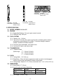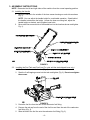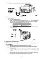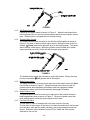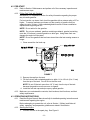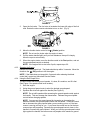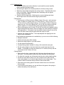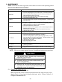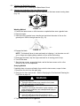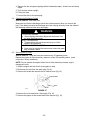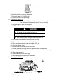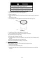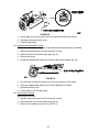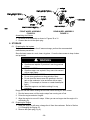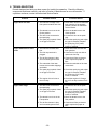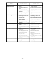
1
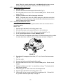
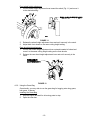
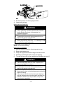
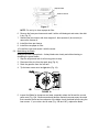
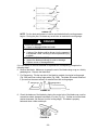
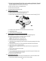
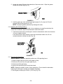
For Serial Nos.
510,000 & Higher
Part No. 103-9832 Rev. A
WARNING
POTENTIAL HAZARD
♦ This product is a piece of power equipment.
WHAT CAN HAPPEN
♦ Failure to follow safe operating practices can result in serious
operator injury or even death.
HOW TO AVOID THE HAZARD
♦ Keep all shields, guards, and safety devices (especially the grass
discharge system) in place and in proper working condition.
♦ Stop engine and wait for all moving parts to stop. Remove spark
plug wire(s) or remove key before adjusting, servicing, or
performing maintenance.
♦ If mower deck becomes clogged, stop engine and wait for all
moving parts to stop. Remove spark plug wire(s) or remove key
before cleaning blockage.
♦ Keep hands, feet, and clothing away from power driven parts.
♦ Keep off mower unless seat platform is provided.
♦ Keep others off mower.
WARNING
POTENTIAL HAZARD
♦ Gasoline is harmful or fatal if swallowed. Long-term exposure to
vapors has caused cancer in laboratory animals.
WHAT CAN HAPPEN
♦ Failure to use caution may cause serious injury or illness.
HOW TO AVOID THE HAZARD
♦ Avoid prolonged breathing of vapors.
♦ Keep face away from nozzle and gas tank/container opening.
♦ Keep away from eyes and skin.
♦ Never siphon by mouth.
IMPORTANT
When the mower is used or operated on any California forest, brush or grass covered land, a working
spark arrester must be attached to the muffler. If not, the operator is violating state law, Section 4442
Public Resource Code. To acquire a spark arrester for your unit, see your Engine Service Dealer.
This spark ignition system complies with Canadian ICES-002
Ce système d’allumage par ètincelle de vèhicule est conforme à la norme NMB-002 du Canada
The enclosed Engine Owner’s Manual is supplied for information regarding The U.S.
Environmental Protection Agency (EPA) and the California Emission Control Regulation of
emission systems, maintenance and warranty.
Keep this engine Owner’s Manual with your unit. Should this engine Owner’s Manual become
damaged or illegible, replace immediately. Replacements may be ordered through the engine
manufacturer.
Exmark reserves the right to make changes or add improvements to its products at any time without
incurring any obligation to make such changes to products manufactured previously. Exmark, or its
distributors and dealers, accept no responsibility for variations which may be evident in the actual
specifications of its products and the statements and descriptions contained in this publication.
-i-
EXMARK PARTS PLUS® PROGRAM
EFFECTIVE DATE: September 1, 1995
Program
If your Exmark dealer does not have the Exmark part in stock,
Exmark will get the parts to the dealer the next business day or
the part will be FREE* Guaranteed!!
How the Program Works
1.
If dealer does not have part in stock for a "down" unit at
the time of request by customer, the dealer contacts his
distributor by 1:00 p.m., local time, and requests Exmark
Parts Plus® shipment of six (6) line items or less.
2.
Distributor ships part(s) to dealer or customer, as
requested by dealer, same day, overnight UPS
Distributor bills dealer for part and freight charges where
applicable.
3.
If distributor does not have the part(s) in stock to satisfy Exmark Parts Plus® order, he contacts Exmark by 3:00 p.m.,
central time, with an Exmark Parts Plus® order of six (6) line items or less.
4.
If order is received by 3:00 p.m. central time, Exmark ships part(s) direct to dealer or customer, as requested by
distributor, same day, overnight UPS, Exmark bills the distributor for parts and shipping charges, where applicable.
5.
The customer pays for the part and freight if it is shipped under the Exmark Parts Plus® and if it arrives in
accordance to the program.
6.
Who pays for the part and freight if it fails to arrive overnight in accordance to the program?
A. Under any circumstance the customer does not pay.
B. If the part does not arrive overnight due to:
1. The dealer not submitting the Exmark Parts Plus® order to his Exmark distributor by 1:00 p.m., the dealer
pays for the part and freight.
2. The Distributor being unable to ship the part the same day or not submitting the Exmark Parts Plus® order
to Exmark by 3:00 p.m., central time, the Distributor pays for the part and freight.
3. Exmark being unable to ship the part and the Exmark parts order is received by 3:00 p.m., central time,
Exmark pays for the part and freight.
4. If the part does not arrive overnight due to the shipper (UPS), the shipper pays for the freight and Exmark
pays for the part.
The following restrictions apply -- The Exmark Parts Plus® Program is available only through participating Exmark
Dealers and applies only to orders submitted on this program Monday through Thursday. Parts Plus service is available
only in the 48 contiguous United States. UPS has initiated a Saturday delivery program to many areas of the continental
United States and can be requested for an overnight shipment on Friday to be delivered Saturday. The next day air
charge, plus the Saturday delivery fee will be the responsibility of the purchaser. Exmark Mfg. will assume no
responsibility for Saturday delivery shipments. To qualify, all Exmark Parts Plus® orders must be received by Exmark by
3:00 p.m., central time. Orders must be six (6) line items or less. Exclusions from the Exmark Parts Plus® Program are:
Any wholegood or accessory in its entirety, engines and engine replacement parts, 5-speed Peerless transmissions and
5-speed transaxles, hydraulic or hydrostatic wheel motors, cutter decks and engine decks or any item exceeding United
Parcel Service size and weight restrictions.
Due to UPS restrictions, aerosol spray paint is considered a hazardous material and cannot be shipped via UPS next day
or Second Day Air.
Exmark Manufacturing stocks a limited supply of parts for transaxles, pumps and wheel motors. These parts can be
ordered for Next Day Air shipment but will not be guaranteed per the Parts Plus Program.
- ii -
CONGRATULATIONS on the purchase of your Exmark Mower. This product has been carefully
designed and manufactured to give you a maximum amount of dependability and years of troublefree operation.
OPERATOR'S MANUAL
This manual contains assembly, operating, maintenance, adjustment, and safety instructions for
your Exmark mower.
BEFORE OPERATING YOUR MOWER, CAREFULLY READ THIS MANUAL IN ITS ENTIRETY.
By following the operating, maintenance, and safety instructions, you will prolong the life of your
mower, maintain its maximum efficiency, and promote safe operation.
If additional information is needed, or should you require trained mechanic service, contact your
authorized Exmark equipment dealer or distributor.
All Exmark equipment dealers and distributors are kept informed of the latest methods of servicing
and are equipped to provide prompt and efficient service in the field or at their service stations. They
carry ample stock of service parts or can secure them promptly for you from the factory.
All Exmark parts are thoroughly tested and inspected before leaving the factory; however, attention
is required on your part if you are to obtain the fullest measure of satisfaction and performance.
- iii -
TABLE OF CONTENTS
PAGE
1. SAFETY
1.1
1.2
1.3
1.4
1.5
1.6
Safety Alert Symbol .................................................................................... 1
Training....................................................................................................... 1
Preparation .............................................................................................. 1-3
Operation................................................................................................. 3-5
Maintenance & Storage ........................................................................... 5-6
Safety Signs ............................................................................................ 6-7
2. SPECIFICATIONS
2.1
2.2
2.3
2.4
2.5
2.6
Model Numbers .......................................................................................... 7
Engine ........................................................................................................ 7
Fuel System................................................................................................ 7
Transmission .............................................................................................. 7
Deck ........................................................................................................... 7
Dimensions................................................................................................. 7
3. ASSEMBLY INSTRUCTIONS
3.1
3.2
3.3
Installing the Handle ................................................................................... 8
Installing the Fuel Tank and Fuel Line .................................................... 8-9
Service the Engine ..................................................................................... 9
4. OPERATION INSTRUCTIONS
4.1
4.2
4.3
Controls ................................................................................................. 9-10
Pre-Start ................................................................................................... 11
Operating Instructions ......................................................................... 11-17
5. MAINTENANCE
5.1
5.2
5.3
5.4
5.5
5.6
5.7
5.8
5.9
5.10
5.11
5.12
5.13
5.14
5.15
5.16
Checking the Engine Oil Level ................................................................. 18
Checking the Blade Brake Clutch............................................................. 19
Cleaning the Underside of the Lawn Mower Housing ......................... 19-20
Cleaning the Discharge Tunnel ............................................................... 20
Servicing the Air Filter ......................................................................... 20-21
Maintaining the Blade .......................................................................... 21-23
Cleaning the Under the Cover .................................................................. 23
Emptying the Fuel Tank and Cleaning the Fuel Filter ......................... 23-24
Lubricating the Pivot Arms ....................................................................... 24
Adjusting the Self-Propelled Drive............................................................ 24
Servicing the Spark Plug ..................................................................... 24-25
Changing the Engine Oil........................................................................... 25
Changing the Oil Filter......................................................................... 25-26
Lubricating the Gear Case .................................................................. 26-27
Adjusting the Blade Brake Cable.............................................................. 27
Servicing the Wheels........................................................................... 27-28
6. STORAGE
6.1
6.2
6.3
6.4
Preparing the fuel system......................................................................... 28
Preparing the Engine................................................................................ 28
General Storage Information ............................................................... 28-29
Removing the Lawn Mower from Storage ................................................ 29
7. ACCESSORIES ............................................................................................. 29
8. TROUBLESHOOTING .............................................................................. 30-31
9. WARRANTY .................................................................................................... 32
- iv -
1. SAFETY
This lawn mower meets or exceeds the CPSC blade safety requirements for walkbehind rotary mowers and the B71.4 specifications of the American National Standards
Institute in effect at the time of production.
Exmark designed and tested this lawn mower to offer reasonably safe service; however,
failure to comply with the following instructions may result in personal injury.
1.1 SAFETY ALERT SYMBOL
This SAFETY ALERT SYMBOL
is used both in this manual and on the machine to
identify important safety messages which must be followed to avoid accidents. This
symbol means:
ATTENTION! BECOME ALERT!
YOUR SAFETY IS INVOLVED!
The safety alert symbol appears above information which alerts you to unsafe actions or
situations and will be followed by the word DANGER, WARNING, or CAUTION.
DANGER: White lettering/Red background. Indicates an imminently hazardous situation
which, if not avoided, WILL result in death or serious injury.
WARNING: Black lettering/Orange background. Indicates a potentially hazardous
situation which, if not avoided, COULD result in death or serious injury.
CAUTION: Black lettering/Yellow background. Indicates a potentially hazardous situation
which, if not avoided, MAY result in minor or moderate injury.
1.2 TRAINING
1.2.1
1.2.2
1.2.3
1.2.4
Regard the Exmark mower as a piece of power equipment and teach this regard
to all who operate this unit.
Read the instructions carefully. Familiarize yourself with the controls and the
proper use of the equipment. If the operator(s) or mechanic(s) can not read
English it is the owner’s responsibility to explain this material to them.
Do not allow operation of this machine by untrained personnel. Never allow
children, teenagers, or people unfamiliar with these instructions to use the
mower. Local regulations may restrict the age of the operator.
Avoid mowing while people, especially children, or pets, are nearby. Keep in
mind that the operator or user is responsible for accidents or hazards occurring
to other people or their property.
1.3 PREPARATION
1.3.1
1.3.2
Evaluate the terrain to determine what accessories and attachments are needed
to properly and safely perform the job. Only use accessories and attachments
approved by Exmark.
The use of personal protective equipment, such as (but not limited to) protection
for the eyes, ears, feet, and head is recommended.
CAUTION
POTENTIAL HAZARD
♦ This machine produces sound levels in excess of 85
dBA at the operator’s ear when in operation.
WHAT CAN HAPPEN
♦ Exposure to sound levels of 85 dBA or above for
extended periods of time can cause hearing loss.
HOW TO AVOID THE HAZARD
♦ Wear hearing protection when operating this machine.
-1-
1.3.3
While mowing, always wear substantial footwear and long trousers. Do not
operate equipment when barefoot or when wearing open sandals.
1.3.4
Thoroughly inspect the area where the equipment is to be used and remove all
stones, sticks, wires, bones, and other foreign objects which may damage the
equipment or cause personal injury to the operator or bystanders.
WARNING
POTENTIAL HAZARD
♦ Engine exhaust contains carbon monoxide, which is an
odorless deadly poison.
WHAT CAN HAPPEN
♦ Carbon monoxide can kill you.
HOW TO AVOID THE HAZARD
♦ Do not run engine indoors or in a small confined area
where dangerous carbon monoxide fumes can collect.
DANGER
POTENTIAL HAZARD
♦ In certain conditions gasoline is extremely flammable
and highly explosive.
WHAT CAN HAPPEN
♦ A fire or explosion from gasoline can burn you, others,
and cause property damage.
HOW TO AVOID THE HAZARD
♦ DO NOT smoke while refueling, and stay away from
an open flame or where gasoline fumes may be ignited
by spark.
♦ Refuel only outdoors.
♦ Store gasoline in an approved container and keep it out
of the reach of children.
♦ Add fuel before starting the engine. Never remove the
cap of the fuel tank or add fuel when engine is running
or when the engine is hot.
♦ Never fill the fuel tank so that the gasoline level rises
above a level that is 1/2” (1.3 cm) below the bottom of
the filler neck to allow for gasoline expansion and
prevent fuel spillage.
♦ If fuel is spilled, DO NOT attempt to start the engine.
Move away from the area of the spill and avoid creating
any source of ignition until fuel vapors have dissipated.
♦ Do not operate without entire exhaust system in place
and in proper working condition.
-2-
DANGER
POTENTIAL HAZARD
♦ In certain conditions gasoline is extremely flammable
and highly explosive.
WHAT CAN HAPPEN
♦ A static charge can ignite gasoline vapors. A fire or
explosion from gasoline can burn you, others, and
cause property damage.
HOW TO AVOID THE HAZARD
♦ Purchase and store gasoline only in an approved
container.
♦ Always place gasoline containers on the ground away
from your vehicle before filling.
♦ Do not fill gasoline containers inside a vehicle or on a
truck or trailer bed because interior carpets or plastic
truck bed liners may insulate the container and slow
the loss of any static charge.
♦ When practical, remove gas-powered equipment from
the truck or trailer and refuel the equipment with its
wheels on the ground.
♦ If this is not possible, then refuel such equipment on a
truck or trailer from a portable container, rather than
from a gasoline dispenser nozzle.
♦ If a gasoline dispenser nozzle must be used, keep the
nozzle in contact with the rim of the fuel tank or
container opening at all times until fueling is complete.
WARNING
POTENTIAL HAZARD
♦ Gasoline vapor can collect inside enclosed trailers and
may be ignited by electrical sparks or hot
engine/exhaust components.
WHAT CAN HAPPEN
♦ Explosion and fire may occur, resulting in property
damage, personal injury and/or death.
HOW TO AVOID THE HAZARD
♦ Provide adequate ventilation of any enclosed trailer to
prevent build up of gasoline vapors, especially at floor
level.
♦ Refuel only outdoors, never inside an enclosed trailer.
♦ Be sure all fuel tanks and gasoline storage containers
have proper caps installed to prevent spillage and
minimize vapor escaping into the trailer.
♦ Do not place any equipment that is leaking gasoline in
an enclosed trailer.
1.4 OPERATION
Although hazard control and accident prevention are partially dependent upon the
design and configuration of the equipment, these factors are also dependent upon
the awareness, concern, prudence, and proper training of the personnel involved in
the operation, transport, maintenance, and storage of the equipment. It is essential
that all Operator Safety Mechanisms be connected and in operating condition prior
to use for mowing.
-3-
WARNING
POTENTIAL HAZARD
♦ Hands, feet, hair, clothing, or accessories can become
entangled in rotating parts.
WHAT CAN HAPPEN
♦ Contact with rotating parts can cause traumatic amputation
or severe lacerations.
HOW TO AVOID THE HAZARD
♦ Do not operate the machine without guards, shields and
safety devices in place and working.
♦ Keep hands, feet, hair, jewelry, or clothing away from
rotating parts.
1.4.1
Give complete, undivided attention to the job at hand.
1.4.2
Mow only in daylight or in good artificial light, keeping away from holes or hidden
hazards. DO NOT operate the mower when children or others are in the area.
1.4.3
1.4.4
When feasible, avoid operating the equipment in wet grass.
Use EXTREME caution when mowing and/or turning on slopes as loss of traction
and/or tip-over could occur. The operator is responsible for safe operation on
slopes.
DANGER
POTENTIAL HAZARD
♦ Mowing on wet grass or steep slopes can cause sliding and
loss of control.
WHAT CAN HAPPEN
♦ Loss of control and/or loss of operator’s footing could result
in a fall with an arm or leg getting under the mower or
engine deck, which may result in serious injury or death.
HOW TO AVOID THE HAZARD
♦ Mow across slopes, never up and down.
♦ Do not mow slopes when grass is wet.
♦ Do not mow near drop-offs or near water.
♦ Do not mow excessively steep slopes.
♦ Reduce speed and use extreme caution on slopes.
♦ Avoid sudden turns or rapid speed changes.
• Progressively greater care is needed as the slope increases.
• Watch for ditches, holes, rocks, dips, and rises that change the operating
angle, as rough terrain could overturn the machine.
• Remove or mark obstacles such as rocks, tree limbs, etc. from the mowing
area. Tall grass can hide obstacles.
• Use extreme care with grass catchers or attachments. These can change the
stability of the machine and cause loss of control.
1.4.5
Use EXTREME caution when backing up. LOOK BEHIND YOU!!
1.4.6
Stop the blades when crossing surfaces other than grass, if mower must be tilted
for transportation, and when transporting the mower to and from the area to be
mowed.
1.4.7
Never operate the mower with damaged guards, shields, or covers. Always
have safety shields, guards, switches, and other devices in place and in proper
working condition.
-4-
1.4.8
Do Not change the engine governor settings or overspeed the engine. Operating
an engine at excessive speed may increase the hazard of personal injury.
1.4.9
Never attempt to make wheel height adjustments while the engine is running.
1.4.10
Start the engine carefully according to instructions with feet well away from the
blades.
1.4.11
Keep hands, feet, and clothing away from rotating parts while the mower is being
operated. Keep clear of the discharge opening at all times.
1.4.12
Stop the engine, wait for all moving parts to stop, and remove the spark plug
wire(s) and/or remove key:
a)
Before checking, cleaning, or working on the mower.
b)
After striking a foreign object (inspect the mower for damage and make
repairs before restarting and operating the mower).
c)
Before clearing blockages.
d)
Whenever you leave the mower.
1.4.13
Stop the engine and wait for all moving parts to stop before refueling.
1.4.14
The fuel system is provided with a shut-off valve. The fuel shut-off valve is used
to shut off the fuel when:
a)
The machine will not be used for a few days
b)
During transport to and from the job
c)
When parking inside a building
1.4.15
This mower was designed for one operator only. Keep all others away from
mower during operation.
1.4.16
Do Not mow with the discharge deflector raised, removed or altered unless
there is a grass collection system or mulch kit in place and working properly.
1.4.17
Grass catcher components are subject to wear, damage and deterioration, which
could expose moving parts or allow objects to be thrown. Frequently check the
components and replace them with the manufacturer’s recommended parts
when necessary.
1.4.18
Be aware of the mower discharge and direct discharge away from others.
1.4.19
Do Not operate mower under the influence of alcohol or drugs.
1.4.20
Use care when approaching blind corners, shrubs, trees, or other objects that
may obscure vision.
1.5 MAINTENANCE AND STORAGE
1.5.1
For engine maintenance, follow the engine manufacturer's recommendations
precisely as stated in the engine manual.
1.5.2
Keep engine and engine area free from accumulation of grass, leaves, excessive
grease or oil, and other debris which can accumulate in these areas. These
materials can become combustible and may result in a fire.
1.5.3
Store fuel in a container specifically designed for this purpose. Store the fuel
container in a cool, dry place.
1.5.4
Keep the mower and fuel container in locked storage to prevent children from
playing or tampering with them.
1.5.5
Gasoline powered equipment or fuel containers should not be stored in a basement
or any enclosed area where open pilot lights or heat appliances are present.
1.5.6
Maximum mowing results and safety can only be achieved if the mower is
properly maintained and operated correctly.
1.5.7
Check all bolts frequently to maintain proper tightness.
-5-
1.5.8
Keep all guards, shields and safety devices in place and in safe working condition.
1.5.9
Frequently check for worn or damaged components that could create a hazard.
1.5.10
All replacement parts must be the same as or equivalent to the parts supplied as
original equipment.
1.6 SAFETY SIGNS
1.6.1
Keep all safety signs legible. Remove all grease, dirt and debris from safety
signs and instructional labels.
1.6.2
Safety signs must be replaced if they are missing or illegible.
1.6.3
When new components are installed, be sure that current safety signs are
affixed to the replaced components.
1.6.4
New safety signs may be obtained from your authorized Exmark equipment
dealer or distributor or from Exmark Mfg. Co. Inc.
1.6.5
Safety signs can be affixed by peeling off the backing to expose the adhesive
surface. Apply only to a clean, dry surface. Smooth to remove any air bubbles.
1.6.6
Familiarize yourself with the following safety signs and instruction labels. They
are critical to the safe operation of your Exmark commercial mower.
PART NO.: 68-7410
LOCATION: Top Center of Mower Deck
98-4387
PART NO.: 98-4387
LOCATION: Center of Handle Bar
PART NO.: 43-8480
LOCATION: Top Surface of Mower Deck on
Left and Right Sides
PART NO.: 52-2610
LOCATION: Back of Mower Deck
PART NO.: 52-2620
LOCATION: LH Rear Corner of
Mower Deck
PART NO.: 98-5954
LOCATION: Top of Mower Deck, Under
Belt Cover
-6-
PART NO.: 1-213240
LOCATION: On Rear Discharge
Chute Cover
PART NO.: 103-6329
LOCATION: Top Surface of
Shifter Control
PART NO.: 103-6328
LOCATION: Top Surface of
Throttle Control
2. SPECIFICATIONS
2.1 MODEL NUMBER: M266KASPC
2.2 ENGINE
2.2.1 Engine Specifications: See your engine owner's manual.
2.2.2 RPM (No Load): 3600 rpm
2.3 FUEL SYSTEM
2.3.1 Capacity: 4 qt. (3.8 liter)
2.3.2 Type of Fuel: Use only clean, fresh, regular grade, unleaded gasoline with the
pump sticker octane rating of 87 or higher. In countries using the research
method, it should be 90 octane minimum.
2.3.3 Fuel Filter: Non–replaceable, on left side of tank
2.3.4 Fuel Shut Off Valve: on left side of tank
2.4 TRANSMISSION
2.4.1 3 speeds forward
st
Speed range: 1 - 2.0 mph (3.2 km/h)
nd
2 - 2.9 mph (4.6 km/h)
rd
3 - 4.1 mph (6.6 km/h)
2.5 DECK
2.5.1 Cutting Width:
26.1” (66 cm)
2.5.2 Blade Brake: When the blade engagement control is moved to the disengaged
position a friction brake pad stops the rotation of the blades.
2.5.3 Cutting Height: Adjusts in 1/2" (.64 cm) increments from 1” to 4” (2.5 cm-10.6 cm).
2.6 DIMENSIONS
2.6.1 Overall Width: 27” (69 cm)
2.6.2 Overall Length and Height (Adjustable):
Handle Setting
Length
Height
High
69” (175.2 cm)
44” (111.8 cm)
Low
73” (185.4 cm)
37.5” (95.3 cm)
2.6.3 Curb Weight: 160 lbs (73 kg)
-7-
3. ASSEMBLY INSTRUCTIONS
NOTE: Determine the left and right sides of the machine from the normal operating position.
3.1 Installing the Handle
1.
Mount the handle to the outside of the lawn mower housing on each side as shown
Fig. 1).
NOTE: You can adjust the handle height for comfortable operation. Stand behind
the handle to determine the height. Loosen the lower mounting bolt, adjust the
handle height as desired, and re-tighten lower bolts.
2.
Move cable ties on each side of the handle bar into the locations shown and tighten
Fig. 1).
FIGURE 1
3.2
Installing the Fuel Tank and Fuel Line (For units with the tank shipped loose only)
1. Position the tank onto the bracket (Fig. 2).
2. Start the 3 self-tapping screws into the tank and tighten (Fig. 2). Do not overtighten
the screws.
FIGURE 2
3. Route the fuel line from the tank to the carburetor fuel fitting.
4. Remove the red cap from the end of the fuel line and from the end of the carburetor
fuel fitting (Fig. 3).
5. Slide the end of the fuel line onto the carburetor fuel fitting (Fig. 3).
-8-
6. Secure the fuel line in place with the fuel line clamp (Fig. 3).
FIGURE 3
3.3
Service the Engine
3.3.1 Filling the Crankcase with Oil
Initially, fill the crankcase with 30 ounces (0.88 liters) of oil. Use only high-quality
SAE 30 or SAE 10W-30 weight detergent oil that has the American Petroleum
Institute (API) service classification SF, SG, SH, or SJ.
Oil Capacity
With Oil Filter
30 ounces (0.88 L)
Before each use, ensure that the oil level is between the Add and Full marks on
the dipstick (Fig. 8).
FIGURE 4
4. OPERATION INSTRUCTIONS
NOTE: Determine the left and right sides of the machine from the normal operating position.
4.1 CONTROLS
4.1.1
Familiarize yourself with the controls and operation of the unit.
Carefully read the following information about the controls and their operation.
4.1.2
Blade Control Bail:
Located on the upper handle as shown in Figure 5. When the blade control bail
is depressed, the system senses that the operator is in the normal operator's
position.
When the blade control bail is released, the system senses that the operator has
moved from the normal operating position and will stop the blade.
-9-
FIGURE 5
4.1.3
Self-Propel Drive Bail:
Located on the upper handle as shown in Figure 5. When the self-propel drive
bail is squeezed, the unit will move forward at the speed set on the speed control
lever. When this bail is released the unit will stop moving.
4.1.4
Throttle-Choke Control:
The throttle-choke control is located on the left side of the handles as shown in
Figure 6. The lever is used to control engine speed. Moving the lever to the full
(Choke) position will place the lever in the choke position. The choke
forward
aids in starting a cold engine. Moving the throttle control forward will increase
engine speed and moving it to the rear will decrease engine speed.
FIGURE 6
The throttle-choke control also includes an engine kill position. Moving the lever
(Off) position will kill the engine.
into the full rearward
4.1.5
Blade Control Lever:
The blade control lever is located on the right side of the handle next to the Blade
Control Bail as shown in Figure 6. Moving the blade control lever into the full
forward position while depressing the blade control bail engages the blade.
Releasing the blade control bail automatically disengages the blades.
4.1.6
Speed Control Lever:
The ground speed control is located on the right side of the handles below the
blade engagement lever as shown in Figure 6. The ground speed control has
three settings which control the ground speed of the mower.
4.1.7
Fuel Shut-Off Valve:
The fuel shut off valve is installed on the fuel tank under the fuel cap.
The fuel shut off valve shuts off the flow of fuel when the machine will not be used
for a few days, when parking inside a building, and during transport to and from
the job. Rotate the valve clockwise to shut off fuel. Rotate the valve counterclockwise to turn on fuel.
- 10 -
4.2 PRE-START
4.2.1
Refer to Section 5 Maintenance and perform all of the necessary inspection and
maintenance steps.
4.2.2
Fill the Fuel Tank with Gasoline
See Section 1.3 Preparation section for safety information regarding the proper
way to handle gasoline.
For best results, use clean, fresh, lead free gasoline with an octane rating of 87 or
higher. To ensure freshness, purchase only the quantity of gasoline that you
expect to use in 30 days. Using unleaded gasoline results in fewer combustion
deposits and longer engine life.
NOTE: Do not add oil to the gasoline.
NOTE: Do not use methanol, gasoline containing methanol, gasohol containing
more the 10% ethanol, premium gasoline or white gas. Using these fuels can
damage the engine’s fuel system.
NOTE: Do not use gasoline that has been stored since the last mowing season or
longer.
1. Clean around the fuel tank cap.
FIGURE 7
2. Remove the cap from the tank.
3. Fill the fuel tank with unleaded gasoline to within 1/4 to 1/2 inch (6 to 13 mm)
from the top of the tank. Do not fill into the filler neck.
NOTE: Do not fill the tank more than 1/4” (6 mm) from the top of the tank
because the gasoline must have room to expand.
4. Install the fuel tank cap and wipe up any spilled gasoline
4.2.3
Make sure you understand the controls, their locations, their functions, and their
safety requirements.
4.3 OPERATING INSTRUCTIONS
4.3.1
Read the Engine Owner's Manual carefully for detailed operating instructions and
maintenance regarding the engine.
Before attempting to operate the unit, refer to Section 1 (Safety) and follow all
safety, operating, and preparation guidelines as stated in that section.
4.3.2
Starting the Engine
1.
Connect the wire to the spark plug. See Figure 8.
- 11 -
2.
3.
FIGURE 8
Open the fuel valve. The fuel valve is located at the lower left edge of the fuel
tank. Rotate the valve counter-clockwise to turn on fuel. (Fig. 9)
FIGURE 9
Move the throttle-choke control to the
(Choke) position.
NOTE: Do not use the choke when the engine is warm.
4.
Pull the starter handle lightly until you feel resistance, then pull it sharply.
Allow the rope to return slowly.
5.
When the engine starts, move the throttle control to the Fast position, and set
the ground speed control as desired.
NOTE: If the engine fails to start after 3 pulls, repeat steps 3-6.
4.3.3
Stopping the Engine:
Release the blade control bail. The blade should stop within 3 seconds. Move the
throttle to the
(Off) position to kill the engine.
NOTE: If the blade does not stop within 3 seconds after releasing the blade
control bail, contact an Authorized Service Dealer.
4.3.4
Using the Self-Propel Drive:
The lawn mower has three ground speeds. 1 is slow, 2 is medium, and 3 is fast
(See Figure 6 for speed control lever location).
1.
Start the engine.
2.
Using the ground speed control, select the desired ground speed.
3.
Squeeze the drive bail against the handle (See Figure 5).
NOTE: Do not shift speeds while squeezing the ground speed control against
the handle. This can damage the transmission. Release the ground speed
control before changing speeds.
NOTE: You can vary the ground speed by increasing or decreasing the
distance between the ground speed control and the handle. Lower the control
bar to decrease the ground speed when you are making a turn or if the lawn
mower is moving too fast for you. If you lower the control bar too far the lawn
mower stops self-propelling. Squeeze the ground speed control closer to the
handle to increase the ground speed. When you hold the ground speed control
tight against the handle, the lawn mower self-propels at the maximum ground
- 12 -
speed. Move the ground speed control to the Neutral position when you use
the lawn mower for trimming or whenever you leave the lawn mower.
4.3.5
Operating the Blade Control Lever:
1.
Start the engine.
2.
Squeeze the blade control bail against the handle (Fig. 5).
3.
Move the blade control lever to the full forward Latch position. Blades should
engage (Fig. 6).
4.
Release the blade control bail to disengage the blades.
NOTE: The blade control lever will release rapidly when the blade control bail
is released. To avoid minor injury, keep hands clear of the blade control lever
when the blade control bail is released.
4.3.6
Checking the Blade Brake Clutch:
Check the Blade Brake Clutch (BBC) system before each use to ensure that it is
operating properly.
Normal Test:
1.
Stop the engine and wait for all moving parts to stop.
2.
Move the lawn mower onto a paved surface in a non-windy area.
3.
Set all four wheels in to the 2-1/2 in. (64 mm) cutting height (Fig. 11).
4.
Set the ground speed selector to the N (Neutral) position .
5.
Take a half sheet of newspaper and crumple it into ball small enough to go under
the deck (about three inches or 76 mm in diameter) as shown in Figure 10.
FIGURE 10
6.
Place the ball of newspaper five inches (12.7 cm) in front of the lawn mower
(Fig. 10).
7.
Start the engine.
8.
Squeeze the blade control bail against the handle.
9.
Move the blade control lever to the full forward Latch position. Blades should
engage.
10. Release the blade control bail. You should hear a “bang.” The blade should
stop in three seconds.
11. Immediately push the lawn mower over the newspaper ball.
12. Stop the engine and wait for all moving parts to stop.
13. Walk around the lawn mower to check for the newspaper ball. If the ball did
not go under the deck, repeat step 7 through 12.
- 13 -
14. Pull the lawn mower away from the newspaper. If the newspaper ball
unravels or is shredded, the blade has not properly stopped, resulting in an
unsafe operating condition. Contact an Authorized Service Dealer.
DANGER
POTENTIAL HAZARD
♦ If the blade brake clutch system is inoperative, the
blade will continue to rotate when you release the blade
control bail.
WHAT CAN HAPPEN
♦ Contact with the blade could occur, causing serious
injury.
HOW TO AVOID THE HAZARD
♦ Check the BBC operation before each use.
♦ Never use the BBC-equipped lawn mower with an
inoperative safety system.
♦ Take your lawn mower to an Authorized Service Dealer
for repair if the safety system fails to operate properly.
Test Using the Grass Bag:
4.3.8
1.
Install the empty grass bag on the bag support tabs.
2.
Start the engine.
3.
Squeeze the blade control bail against the handle.
4.
Move the blade control lever to the full forward Latch position. The bag should
begin to inflate, indicating that the blade is engaged and rotating.
5.
Release the blade control bail. If the bag does not immediately deflate, it
indicates that the blade is still rotating. The blade brake clutch mechanism may
deteriorating, and, if ignored could result in an unsafe operating condition. Have
the lawn mower inspected and serviced by an Authorized Service Dealer.
Adjusting the Cutting Height
The front wheels are adjusted individually with a wheel height adjustment lever. The
rear wheels are adjusted together with the wheel height adjustment lever located
above the left rear wheel. The cutting heights are listed in the following table.
Cutting Heights
1.0 in (25 mm)
1.5 in (38 mm)
2.0 in (51 mm)
2.5 in (64 mm)
3.0 in (76 mm)
3.5 in (89 mm)
4.0 in (102 mm)
DANGER
POTENTIAL HAZARD
♦ Adjusting the cutting height levers could bring your
hands into contact with a moving blade.
WHAT CAN HAPPEN
♦ A moving blade can cause serious injury.
HOW TO AVOID THE HAZARD
♦ Stop the engine and wait for all movement to stop
before adjusting the cutting height.
♦ Do not put your fingers under the housing when
adjusting the cutting height.
- 14 -
Front wheel height adjustment:
1.
Pull the wheel height adjustment lever toward the wheel (Fig. 11) and move it
to the desired setting.
2.
FIGURE 11
Release the wheel height adjustment lever and set it securely in the notch.
3.
Adjust both front wheels to the same cutting height setting.
Rear wheel height adjustment:
1.
Pull the rear wheel height adjustment lever outward towards left wheel and
move it to the same cutting height setting as the front wheels.
2.
Release the rear wheel height adjustment lever and set it securely in the
notch.
FIGURE 12
4.3.9
Using the Grass Bag
Occasionally, you may wish to use the grass bag for bagging extra long grass,
lush grass, or leaves.
Installing the Grass Bag
1.
Stop the engine and wait for all moving parts to stop.
2.
Open the rear door.
- 15 -
3.
FIGURE 13
Set the bag frame onto the bag support tabs.
4.
Lower door onto bag.
Mowing with the Grass Bag
WARNING
POTENTIAL HAZARD
♦ A worn grass bag could allow small stones and other
similar debris to be thrown in the operator’s or
bystander’s direction.
WHAT CAN HAPPEN
♦ Thrown objects can result serious personal injury or
death to the operator or bystanders.
HOW TO AVOID THE HAZARD
♦ Check the grass bag frequently. If it is damaged, install
a new Exmark replacement bag.
Cut the grass until the bag is full
NOTE: Do not overfill the bag.
Removing the Grass Bag
1.
Stop the engine and wait for all moving parts to stop.
2.
Raise the discharge door.
3.
Grasp the bag handle and lift the bag off the lawn mower.
4.
Gradually tip the bag forward to empty the clippings.
5.
To install the bag, refer to the Installing the Grass Bag on page 15.
DANGER
POTENTIAL HAZARD
♦ If the discharge door does not close completely, the
lawn mower could throw objects.
WHAT CAN HAPPEN
♦ Thrown objects can result serious personal injury or
death to the operator or bystanders.
HOW TO AVOID THE HAZARD
♦ Never open the door to the discharge opening when the
engine is running.
♦ If you cannot close the door because grass clippings
clog the discharge area, stop the engine and clear the
obstruction with a stick, not your hand, until you can
close the door completely.
- 16 -
4.3.10 Operating Tips
• Review the Safety Instructions (Section 1) and read this manual carefully
before operating the lawn mower.
• Set the engine speed to the fastest position for the best cutting results.
• Maintain a sharp blade throughout the cutting season. Periodically file down
nicks on the blade. Replace the blade when necessary with an original
Exmark replacement blade.
• Clean the air filter frequently. Mulching stirs up more clippings and dust
which clogs the air filter and reduces engine performance.
Cutting Grass
• Grass grows at different rates at different times of the year. In the summer
heat, it is best to cut grass at the 2-1/2 inch (64 mm), 3 inch (76 mm), or 31/2 inch (90 mm) cutting height settings. Cut only about a third of the grass
blade at a time. Do not cut below the 2-1/2 inch (64 mm) setting unless the
grass is sparse or it is late fall when grass growth begins to slow down.
• When cutting grass over 6 inches (15 cm) tall, first mow at the highest cutting
height setting and walk slower; then mow again at a lower setting for the best
lawn appearance. If the grass is too long and the leaves clump on top of the
lawn, the lawn mower may plug and cause the engine to stall.
• Alternate the mowing direction. This helps disperse the clippings over the
lawn for even fertilization.
If the finished lawn appearance is unsatisfactory, try one or more of the following:
• Sharpen the blade.
• Walk at a slower pace while mowing.
• Raise the cutting height on your lawn mower.
• Cut the grass more frequently.
• Overlap cutting swaths instead of cutting a full swath with each pass.
• Set the cutting height on the front wheels one notch lower than the rear
wheels. For example, set the front wheels at 2-1/2 inches (64 mm) and the
rear wheels at the 3 inches (76 mm).
Cutting Leaves
• After cutting the lawn, ensure that half of the lawn shows through the cut
leaf cover. You may need to make more than one pass over the leaves.
• For light leaf coverage, set all the wheels at the same cutting height setting.
• If there are more than 5 inches (127 mm) of leaves on the lawn, set the
front cutting height 1 or 2 notches higher than the rear cutting height. This
makes it easier to feed the leaves under the lawn mower deck.
• Slow down your mowing speed if the lawn mower does not cut the leave
finely enough.
• If you mow over oak leaves, you can add lime to the grass in the spring to
reduce the acidity of the oak leaves.
- 17 -
5. MAINTENANCE
NOTE: Determine the left and right sides of the machine from the normal operating position.
Recommended Maintenance Schedule
Service Interval
Each Use
5 Hours
50 Hours
75 Hours
100 Hours
300 Hours
Storage
1
Maintenance Procedure
• Check the engine oil level.
• Check the stopping time of the blade brake. The blade must stop
within 3 seconds of releasing the bail; if it does not; contact an
Authorized Service Dealer for repair.
• Remove grass clippings and dirt from under the housing.
• Clean the discharge tunnel area
• Check the blade and the engine mounting fasteners. Tighten them
if they are loose.
1
• Change the engine oil (without the oil filter).
• Sharpen or replace the blade; maintain it more frequently if the
edge dulls quickly in rough or in sandy conditions.
• Clean the blade brake clutch shield.
• Check for leaks in the fuel system and/or a deteriorating fuel hose.
Replace parts if necessary.
• Remove grass clippings and debris from under the belt cover.
• Lubricate the pivot arms.
• Adjust the self-propel drive system.
• Change the oil filter.
• Inspect the spark plug and replace it if necessary.
• Clean the cooling system; remove grass clippings, debris, or dirt
from the engine air cooling fins and starter. Clean the system more
frequently in dirty or high-chaff conditions.
• Lubricate the gear case.
• Adjust the blade brake cable.
• Service the wheels.
• Replace the paper air filter. Replace it more frequently in dusty
operating conditions.
• Empty the fuel tank before repairs as directed or before storage.
Change the engine oil after the first 5 operating hours.
NOTE: Refer to your engine operator’s manual for additional maintenance procedures.
CAUTION
POTENTIAL HAZARD
♦ If you leave the wire on the spark plug, someone could
accidentally start the engine.
WHAT CAN HAPPEN
♦ Accidental starting of the engine could seriously injure
you or other bystanders.
HOW TO AVOID THE HAZARD
♦ Disconnect the wire from the spark plug before you don
any maintenance. Set the wire aside so that it does not
accidentally contact the spark plug.
5.1
Checking the Engine Oil Level
Service Interval: Before each use.
Make sure that the oil level is between the Add and the Full marks as shown on the
dipstick (Fig. 4). If the oil level is below the Add mark, add oil. Refer to Section 3.4.1
Filling the Crankcase with Oil.
- 18 -
5.2
Checking the Blade Brake Clutch
Refer to Section 4.3.6 Checking the Blade Brake Clutch.
5.3
Cleaning the Underside of the Lawn Mower Housing.
To ensure the best performance, keep the underside of the lawn mower housing clean
(Fig. 14).
Washing Method
FIGURE 14
1. Position the lawn mower on a flat concrete or asphalt surface near a garden hose.
2. Start the engine.
3. Hold the running garden hose a handle level and direct the water to flow on the
ground just in front of the right rear tire (Fig. 15).
G0213
4. Engage the blade.
FIGURE 15
NOTE: The blade will draw in water and wash out clippings. Let the water run until
you no longer see clipping being washed out from under the housing.
5. Disengage the blade, stop the engine and wait for all moving parts to stop.
6. Turn off the water.
7. Start the lawn mower, engage the blade, and let the lawn mower run for a few
minutes to dry out its components.
Scraping Method
If washing does not remove all debris from under the lawn mower, scrape it clean.
1. Disconnect the wire from the spark plug.
2. Drain the fuel from the fuel tank. Refer to Emptying the Fuel tank and Cleaning the
Fuel Filter on page 19.
WARNING
POTENTIAL HAZARD
♦ Tipping the lawn mower may cause the fuel to leak
from the carburetor or the fuel tank.
WHAT CAN HAPPEN
♦ Gasoline is extremely flammable, highly explosive, and
under certain conditions, can cause personal injury or
property damage.
HOW TO AVOID THE HAZARD
♦ Avoid fuel spills by running the engine dry or by
removing the gasoline with a hand pump; never siphon.
3. Tip the lawn mower onto its right side.
- 19 -
4. Remove the dirt and grass clippings with a hardwood scraper. Avoid burrs and sharp
edges.
5. Turn the lawn mower upright.
6. Fill the fuel tank.
7. Connect the wire to the spark plug.
5.4
Cleaning the Discharge Tunnel
Service Interval: After each use.
Always be sure that the discharge tunnel door closes securely when you remove the
bag. If the debris prevents the discharge door form closing securely, clean the inside of
the discharge tunnel and the door thoroughly.
WARNING
POTENTIAL HAZARD
♦ Grass clippings and other objects can be thrown from
an open discharge tunnel.
WHAT CAN HAPPEN
♦ Thrown objects can cause serious injury or kill the
operator or bystanders.
HOW TO AVOID THE HAZARD
♦ Never start or operate the lawn mower unless the grass
bag is locked in place.
5.5
Servicing the Air Filter
Service Interval: Clean the foam pre-cleaner every 25 operating hours.
Replace the paper air filter once every season or every 300 operating hours. (more
frequently in dusty conditions)
NOTE: Do not operate the engine without the air filter assembly; extreme engine
damage will occur.
1. Stop the engine and wait for all moving parts to stop.
2. Disconnect the wire from the spark plug (Fig. 8).
3. Remove the screw that secures the air cleaner cover (Fig 16.)
Paper Air Filter
Screw
G0215
Cover
FIGURE 16
4. Remove the cover and clean it thoroughly (Fig. 16).
5. Remove the paper air filter and discard it as required (Fig. 16).
- 20 -
Paper Air Filter
Foam Pre Cleaner
G0216
Figure 17
NOTE: Do not try to clean a paper air filter.
6. Remove the foam pre-cleaner and wash it with a mild detergent and water, then blot
it dry (Fig 17).
7. Saturate the pre-cleaner with clean engine oil, then squeeze it (do not twist) to
remove the excess oil.
8. Install the foam pre-cleaner.
9. Install the new paper air filter.
10. Install the cover and secure it with the screw.
5.6
Maintaining the Blade
Always mow with a sharp blade. A sharp blade cuts cleanly and without tearing or
shredding the grass blades.
1. Stop the engine and wait for all moving parts to stop.
2. Disconnect the wire from the spark plug (Fig. 8).
3. Drain the gasoline from the fuel tank.
4. Tip the lawn mower onto its right side (Fig. 18).
FIGURE 18
5. Inspect the Blade for sharpness and wear, especially where the flat and the curved
parts meet (Fig. 19A. Because sand and abrasive material can wear away the metal
that connects the flat and curved parts of the blade, check the blade before using the
lawn mower. If you notice a slot or wear (Fig. 19B and 19C), replace the blade.
- 21 -
Sail
Sail
Flat
Sail
Wear
G0219
Slot
FIGURE 19
NOTE: For the best performance, install a new blade before the cutting season
begins. During the year, file down any small nicks to maintain the cutting edge.
DANGER
POTENTIAL HAZARD
♦ A worn or damaged blade can break.
WHAT CAN HAPPEN
♦ A piece of the blade could be thrown into the operator’s
or bystander’s area, resulting in serious personal injury
or death.
HOW TO AVOID THE HAZARD
♦ Inspect the blade periodically for wear or damage.
♦ Replace a worn or damaged blade.
If it is necessary to remove the blade for replacement or sharpening, complete the
following steps:
6. Remove the blade. Make sure to grasp the end of the blade using a rag or a thickly
padded glove. Remove the blade bolt.
7. For Sharpening: File the top side of the blade to maintain its original cutting angle
(Fig. 20A) and inner cutting edge radius (Fig. 20B). The blade will remain balanced
if you remove the same amount of material from both cutting edges.
Cutting Angle
Cutting Edge Radius
G0220
FIGURE 20
8. Check the balance of the blade by placing the center hole of the blade over a nail or
screwdriver shank clamped horizontally in a vise (Fig. 21). If either end of the blade
rotates downward, file that end (not the cutting edge). The blade is properly
balanced when neither end drops.
G0221
FIGURE 21
- 22 -
9. Re-install a sharp balanced Exmark blade, spacer, washer, and blade bolt. The sail of
the blade must point toward the top of the lawn mower housing for proper installation.
Torque the blade bolt to 75-85 ft-lb (102-115 N-m).
10. Return the lawn mower to its upright position.
11. Close fuel valve and refuel.
12. Connect the wire to the spark plug.
5.7
Cleaning Under the Cover:
1. Stop the engine and wait for all moving parts to stop.
2. Disconnect the wire from the spark plug (Fig. 8).
3. Remove the screws that secure the belt cover to the lawn mower housing (Fig. 22).
FIGURE 22
4. Lift off the cover and brush out all the debris around the belt area.
5. Install the belt cover.
6. Connect the wire to the spark plug
5.8
Emptying the Fuel Tank and Cleaning the Fuel Filter:
Service Interval: Clean the fuel filter element every 100 operating hours.
The fuel filter (screen) element is located inside the fuel tank.
1. Stop the engine and wait for it to cool down.
NOTE: Drain gasoline for a cold engine only.
2. Disconnect the wire from the spark plug (Fig. 8).
3. Close the fuel valve located in the tank under the fuel cap by rotating the fuel valve
knob clockwise.
4. Disconnect the fuel line (Fig. 3) by loosening the tube clamp at the carburetor.
5. Open the fuel valve to the open position.
6. Drain the gasoline completely from the tank and fuel line into an approved fuel
container.
7. Remove the fuel tank from the mower.
8. Close the fuel valve.
9. Pour a small amount of fuel in the fuel tank, move the fuel around in the tank, and
pour it out into an approved fuel container.
10. Install the fuel tank and fuel line.
5.9
Lubricating the Pivot Arms
Service Interval: Lubricate after every 50 operating hours or when the season ends.
1. Move the rear wheel cutting height levers to the center setting.
- 23 -
2. Locate the grease fitting on the underside of the mower deck. Wipe the grease
fittings with a clean rag (Fig. 23).
FIGURE 23
3. Install a grease gun onto the fitting and gently apply 2 or 3 pumps of #2 multipurpose lithium base grease (Fig. 23).
NOTE: Excessive grease pressure may damage the seals.
5.10 Adjusting the Self-Propel Drive:
If the lawn mower does not self-propel or has a tendency to creep forward when the
control bar is released, adjust the transmission cable on the deck.
1. If the lawn mower does not self propel, rotate the transmission cable nuts clockwise
1/2 turn to tighten the belt.
If the lawn mower creeps forward, rotate the transmission cable nuts 1/2 turn
counterclockwise to loosen the belt (Fig. 24).
FIGURE 24
5.11 Servicing the Spark Plug:
Service Interval: Check the spark plug after every 100 operating hours.
1. Stop the engine and wait for all moving parts to stop.
2. Disconnect the wire from the spark plug (Fig. 8).
3. Clean around the spark plug.
4. Remove the spark plug from the cylinder head.
NOTE: Replace a cracked, fouled, or dirty spark plug. Do not clean the electrodes
because grit entering the cylinder can damage the engine.
5. Set the gap on the plug to 0.030 in. (0.76 mm) (Fig. 25)
- 24 -
0.030 in. (0.76 mm)
FIGURE 25
6. Install the spark plug and the gasket seal.
7. Torque the plug to 17 ft-lb (23 N-m).
8. Connect the wire to the spark plug.
5.12 Changing the Engine Oil:
Service Interval: Change the oil after the first 5 operating hours (or the first month)
Then after every 50 operating hours (or every 6 months)
1. Run the engine to warm the engine oil.
NOTE: Warm oil flows better and carries more contaminates.
WARNING
POTENTIAL HAZARD
♦ Oil may be hot after engine has been run.
WHAT CAN HAPPEN
♦ Contact with hot oil can cause severe personal injury.
HOW TO AVOID THE HAZARD
♦ Avoid contacting the hot engine oil when you drain it.
2. Stop the engine and wait for all moving parts to stop.
3. Disconnect the wire from the spark plug (Fig. 8).
4. Place a suitable drain pan under the oil drain (Fig. 26).
5. Open the oil drain valve.
6. After draining the oil, close the oil drain valve.
7. Fill the crankcase with fresh oil to the upper limit mark on the dipstick.
8. Insert the dipstick into the filler neck and rotate the cap clockwise until it is tight.
9. Wipe up any spilled oil.
10. Connect the wire to the spark plug.
11. Recycle the used oil according to local codes.
5.13 Changing the Oil Filter:
Service Interval: Replace the oil filter after every 100 operating hours.
FIGURE 26
1. Run the engine to warm the oil.
- 25 -
WARNING
POTENTIAL HAZARD
♦ Oil may be hot after engine has been run.
WHAT CAN HAPPEN
♦ Contact with hot oil can cause severe personal injury.
HOW TO AVOID THE HAZARD
♦ Avoid contacting the hot engine oil when you drain it.
2. Stop the engine and wait for all moving parts to stop.
3. Disconnect the wire from the spark plug (Fig. 8).
4. Drain the engine oil.
5. Place a rag under the oil filter to catch any oil that may leak out as you remove the
filter.
6. Remove the oil filter.
7. Use your finger to coat the gasket on the new filter with clean engine oil.
Gasket
G0228
FIGURE 27
8. Install the new filter and hand tighten it 2/3 turn only.
9. Fill the crankcase to the Full line on the dipstick with fresh oil.
10. Connect the wire to the spark plug.
11. Run the engine for about 3 minutes.
12. Stop the engine, wait for all moving parts to stop, and check for oil leakage around
the filter.
13. Add oil to compensate for the oil in the oil filter.
14. Recycle the used oil filter according to local codes.
5.14 Lubricating the Gear Case:
Service Interval: After every 100 operating, grease the gear case.
1. Remove the grass bag.
2. Remove the gear case access cover.
3. Install a grease gun onto the fitting through the gear case access cover opening
(Fig. 28)
- 26 -
FIGURE 28
4. Gently apply one to two pumps of #2 multi-purpose lithium-base grease.
5. Re-install gear case access cover.
6. Install the grass bag.
5.15 Adjusting the Blade Brake Cable:
Service Interval: Adjust whenever a new blade brake cable assembly it installed
1. Stop the engine and wait for all moving parts to stop.
2. Disconnect the wire from the spark plug (Fig. 8).
3. Remove belt cover
4. Loosen the blade brake cable nuts until the cable conduit slides (Fig. 29)
FIGURE 29
5. Pull the cable to remove the slack, but do not put tension on the spring.
6. Tighten the blade brake cable nut to lock the adjustment in place.
7. Re-install the belt cover.
8. Connect the wire to the spark plug.
5.16 Servicing the Wheels:
Removing the Wheels
1. Stop the engine and wait for all moving parts to stop.
2. Disconnect the wire form the spark plug (Fig. 8).
3. Remove the hardware as shown (Fig. 30 & 31).
- 27 -
FRONT WHEEL ASSEMBLY
FIGURE 30
REAR WHEEL ASSEMBLY
FIGURE 31
Assembling the Wheels
1. Re-install wheel assembly as shown in Figures 30 or 31.
2. Connect the wire to the spark plug.
6. STORAGE
6.1
Preparing the fuel system.
To prepare the lawn mower for off season storage, perform the recommended
maintenance procedures.
Store the lawn mower in a cool, clean, dry place. Cover the lawn mower to keep it clean
and protected.
WARNING
POTENTIAL HAZARD
♦ Gasoline can vaporize if you store it over long periods
of time.
WHAT CAN HAPPEN
♦ Gasoline vapors can explode if they come into contact
with an open flame.
HOW TO AVOID THE HAZARD
♦ Do not store gasoline over long periods of time.
♦ Do not store the lawn mower with gasoline in the fuel
tank or the carburetor in tan enclosure with an open
flame. (For example, a furnace or a water heater pilot
light.)
♦ Allow the engine to cool before storing it in any
enclosure.
Empty the fuel tank when mowing the last time before storing the lawn mower.
1. Run the lawn mower until the engine stops from running out of fuel.
2. Prime the engine and start it again.
3. Allow the engine to run until it stops. When you can no longer start the engine it is
sufficiently dry.
6.2
Preparing the Engine
1. While the engine is still warm, change the oil from the crankcase. Refer to Section
5.13 Changing the Engine Oil.
2. Remove the spark plug (Fig. 8).
- 28 -
3. Using an oil can, add about one tablespoon of oil to the crankcase through the spark
plug hole.
4. Slowly rotate the engine several times, using the starter rope, to distribute the oil.
5. Install the spark plug but do not connect the wire to the spark plug.
6.3
General Storage Information
1. Clean the lawn mower housing. Refer to Section 5.3 Cleaning the Underside of the
Lawn Mower Housing.
2. Clean any dirt and chaff from the cylinder, cylinder head fins, and blower housing.
3. Remove grass clippings, dirt, and grime form the external parts of the engine, the
shrouding, and the top of the lawn mower housing.
4. Refer to Section 5.7 Cleaning the Under the Belt Cover.
5. Check the condition of the blade. Refer to Section 5.6 Maintaining the Blade.
6. Service the air filter. Refer to Section 5.5 Servicing the Air Filter.
7. Lubricate the pivot arms. Refer to Section 5.10 Lubricating the Pivot Arms.
8. Tighten all nuts, bolts, and screws.
9. Touch up all rusted or chipped paint surfaces with paint available form an Authorized
Service Dealer.
6.4
Removing the Lawn Mower from Storage
1. Check and tight all fasteners.
2. Remove the spark plug and spin the engine rapidly by pulling the starter rope to
blow excess oil fro the cylinder.
3. Clean the spark plug or replace it if it is cracked, broken, or if the electrodes are
worn.
4. Install the spark plug and torque it to 17 ft-lb (23 N-m).
5. Perform any needed maintenance procedures.
6. Fill the fuel in the fuel tank with fresh gasoline.
7. Check the engine oil level.
8. Connect the wire to the spark plug.
7. ACCESSORIES
MK26 – Mulch Kit
- 29 -
8. TROUBLESHOOTING
Exmark designed and built your lawn mower for trouble free operation. Check the following
components and items carefully, and refer to Section X Maintenance for more information. If
a problem continues, contact an Authorized Service Dealer.
Problem
Engine does not start
Engine starts hard or loses
power
Engine runs rough
Possible Causes
Corrective Action
1. The fuel tank is empty or the
fuel system contains stale fuel.
1. Drain and/or fill the fuel tank with
fresh gasoline. If the problem
persists, contact an Authorized
Service Dealer.
2. The throttle lever is not in the
Choke position.
2. Move the throttle lever to the
Choke position.
3. The wire is not connected to
the spark plug.
3. Connect the wire to the spark
plug.
4. The spark plug is pitted, fouled,
or the gap is incorrect.
4. Check the spark plug and adjust
the gap if necessary. Replace
the spark plug if it is pitted,
fouled, or cracked.
1. The fuel tank contains stale
fuel.
1. Drain and fill the fuel tank with
fresh gasoline.
2. The fuel cap vent hole is
plugged.
2. Clean the fuel cap vent hole or
replace the fuel cap.
3. The air filter element is dirty
and is restricting the air flow.
3. Clean the air filter pre-cleaner
and/or replace the paper air
filter.
4. The underside of the lawn
mower deck contains clippings
and debris.
4. Clean the underside of the lawn
mower deck.
5. The spark plug is pitted, fouled,
or the gap is incorrect.
5. Check the spark plug and adjust
the gap if necessary. Replace
the spark plug if it is pitted,
fouled, or cracked.
6. The engine oil level is low or
the oil is dirty.
6. Check the engine oil. Change
the oil if it is dirty or add oil if it is
low.
1. The wire is not connected to
the spark plug.
1. Connect the wire to the spark
plug.
2. The spark plug is pitted, fouled,
or the gap is incorrect.
2. Check the spark plug and adjust
the gap if necessary. Replace
the spark plug if it is pitted,
fouled, or cracked.
3. The throttle lever is not in the
Fast position.
3. Move the throttle lever to the
Fast position.
4. The air filter element is dirty
and is restricting the air flow.
4. Clean the air filter pre-cleaner
and/or replace the paper air
filter.
- 30 -
Problem
Lawn mower or engine
vibrates excessively
Uneven cutting pattern
Mower doesn’t cut grass
Discharge chute plugs
Lawn mower does not selfpropel
Possible Causes
Corrective Action
1. The blade is bent or is out of
balance.
1. Balance the blade. If the blade
is bent, replace it.
2. The blade mounting bolt is
loose.
2. Tighten the blade mounting bolt.
3. The underside of the lawn
mower deck contains clippings
and debris.
3. Clean the underside of the lawn
mower deck.
4. The engine mounting bolts are
loose.
4. Tighten the engine mounting
bolts.
1. All four wheels are not at the
same height.
1. Place all four wheels at the
same height.
2. The blade is dull.
2. Sharpen and balance the blade.
3. You are mowing in the same
pattern repeatedly.
3. Change the mowing pattern.
4. The underside of the lawn
mower deck contains clippings
and debris.
4. Clean the underside of the lawn
mower deck.
1. The blade disengages while
mowing.
1. Replace blade drive belt.
2. The blade drive belt is worn or
broken.
2. Replace blade drive belt
1. The throttle lever is not in the
Fast position.
1. Move the throttle lever to the
Fast position.
2. The cutting height is too low.
2. Raise the cutting height.
3. You are mowing too fast.
3. Slow down.
4. The grass is wet.
4. Allow the grass to dry before
mowing.
5. The underside of the lawn
mower deck contains clippings
and debris.
5. Clean the underside of the lawn
mower deck.
1. The self-propel drive cable is
out of adjustment or is
damaged.
1. Adjust the self-propel drive
cable. Replace the cable if
necessary.
- 31 -
9.
2-Year Limited Warranty
Exmark Turf Equipment
(For units purchased on or after October 1, 2004)
Conditions and Products Covered
Exmark Mfg. Co. Inc. and its affiliate, Exmark Warranty
Company, pursuant to an agreement between them, jointly
warrant on the terms and conditions herein, that we will repair,
replace or adjust any part manufactured by Exmark and found
by us (in the exercise of our reasonable discretion) to be
defective in factory materials or workmanship for a period of
two years.
This warranty applies to Exmark turf equipment purchased on
or after October 1, 2004 sold in the US or Canada. This
warranty may only be assigned or transferred to a second (or
third) owner by an authorized Exmark dealer. The warranty
period commences upon the date of the original retail
purchase.
•
•
•
•
•
•
Products
Warranty Period
All Products (except as noted below)
2 years
All Attachments and Accessories
1 year
Metro 21 and Metro 26 Series
1 year
Belts and Tires
90 days
Battery
1 Year Prorated
Engine*
Warranty is covered by engine manufacturer
*Please refer to the engine manufacturer’s warranty statement
that is included in the literature packet. We are not authorized
to handle warranty adjustments on engines.
This warranty only includes the cost of parts and labor.
Items and Conditions Not Covered
This warranty does not cover the following:
•
Pickup and delivery charges to and from any authorized
Exmark Service Dealer.
•
Any damage or deterioration due to normal use, wear
and tear, or exposure.
•
Cost of regular maintenance service or parts, such as
filters, fuel, lubricants, tune-up parts, and adjustments.
•
Any product or part which has been altered or misused
or required replacement or repair due to normal wear,
accidents, or lack of proper maintenance.
•
Any repairs necessary due to use of parts, accessories
or supplies, including gasoline, oil or lubricants,
incompatible with the turf equipment or other than as
recommended in the operator's manual or other
operational instructions provided by Exmark.
All warranty work must be performed by an authorized Exmark
Service Dealer using Exmark approved replacement parts.
Instructions for Obtaining Warranty Service
1. Contact any Exmark Service Dealer to arrange service at
their dealership. To locate a dealer convenient to you,
access our website at www.exmark.com. U.S. Customers
may also call 402-223-6375.
2. Bring the product and your proof of purchase (sales
receipt) to the Exmark Service Dealer.
If for any reason you are dissatisfied with the Service Dealer’s
analysis or with the assistance provided, contact us at:
Exmark Customer Service Department
The Exmark Warranty Company
2101 Ashland Avenue
Beatrice, NE 68310
402-223-6375 or
[email protected]
- 32 -
Owner’s Responsibilities
The Exmark turf equipment, including any defective part,
must be returned to an authorized Exmark service dealer
within the warranty period. This warranty extends only to
turf equipment operated under normal conditions. You
must properly service and maintain your Exmark product
as described in the operator’s manual. Such routine
maintenance, whether performed by a dealer or by you, is
at your expense.
As a condition to this warranty, customer shall have read
the operator's manual and shall have completed and
submitted to Exmark Warranty Company, within the
prescribed time, the Exmark warranty registration.
General Conditions
The sole liability of Exmark and Exmark Warranty Company
with respect to this warranty shall be repair and replacement
as set forth herein. Neither Exmark nor Exmark Warranty
Company shall have any liability for any other cost, loss
or damage, including but not limited to, any incidental
or consequential loss or damage.
In particular, we shall have no liability or responsibility for:
•
Expenses related to gasoline, oil or lubricants.
•
Travel time, overtime, after hours time or other
extraordinary repair charges or charge relating to
repairs or replacements outside of normal business
hours at the place of business of the authorized
Exmark service dealer.
•
Rental of like or similar replacement equipment
during the period of any warranty, repair or
replacement work.
•
Any telephone or telegram charges or travel charges.
•
Loss or damage to person or property other than that
covered by the terms of this warranty.
•
Any claims for lost revenue, lost profit or additional
cost as a result of a claim of breach of warranty.
•
Attorney's fees.
No Claim of breach of warranty shall be cause for
cancellation or rescission of the contract of sale of any
Exmark mower.
There are no understandings, agreements, representations,
or warranties, express or implied, including but not limited to
any regarding the merchantability (that product is fit for
ordinary use) or fitness for use (that product is fit for a
particular purpose), not specified herein, respecting the
equipment which is the subject of this warranty.
Some states do not allow exclusions of incidental or
consequential damages, or limitations on how long an
implied warranty lasts, so the above exclusions and
limitations may not apply to you.
This warranty gives you specific legal rights, and you may
also have other rights which vary from state to state.
NOTES
- 33 -
SERVICE RECORD
Date
Description of Work Done
Service Done By
- 34 -
SEE EXMARK’S COMPLETE
LINE OF ACCESSORIES
RIDING ACCESSORIES
CUSTOM RIDE SEAT SUSPENSION SYSTEM
DECK LIFT ASSIST KIT
HITCH KIT
LIGHT KIT
MICRO-MULCH SYSTEM
ROLL OVER PROTECTION SYSTEM (ROPS)
SNOW BLADE
SUN SHADE
TRASH CONTAINER
TURF STRIPER
ULTRA VAC COLLECTION SYSTEM
ULTRA VAC QUICK DISPOSAL SYSTEM
WALK BEHIND ACCESSORIES
GRASS CATCHER
MICRO-MULCH SYSTEM
STEERABLE SULKY
SULKY HITCH KIT
TURF STRIPER
EZ-RIDER
Check us out on the Web:
www.exmark.com
WARNING
The engine exhaust from this product
contains chemicals known to the State of
California to cause cancer, birth defects, or
other reproductive harm.
© 2005 EXMARK MFG. CO. INC.
INDUSTRIAL PARK BOX 808
BEATRICE, NE 68310
PART NO. 103-9832 Rev. A
(402) 223-6300
FAX (402) 223-5489
ALL RIGHTS RESERVED
PRINTED IN U.S.A.
®
MFG. CO. INC.