1
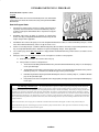
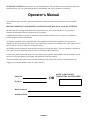
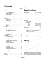
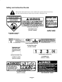
METRO 21 Operator’s Manual 3321–185 Part NO. 850553 WARNING FAILURE TO FOLLOW CAUTIOUS OPERATING PRACTICES CAN RESULT IN SERIOUS OPERATOR INJURY. CAUTION 1. Keep all shields, guards and safety devices (especially grass discharge system) in place and in proper working condition. 2. Stop engine and remove spark plug wire(s) or remove key before adjusting, servicing, or performing maintenance. 3. When mower deck becomes clogged, stop engine and remove spark plug wire(s) or remove key before cleaning blockage. 4. Keep hands, feet, and clothing away from power-driven parts. 5. Keep off mower unless seat or platform is provided. 6. Keep others off mower. WARNING HEALTH WARNING GASOLINE CHEMICALS KNOWN TO THE STATE TO CAUSE CANCER, BIRTH DEFECTS, OR OTHER PRODUCTIVE HARM ARE FOUND IN GASOLINE, CRUDE OIL, AND MANY OTHER PETROLEUM PRODUCTS AND THEIR VAPORS, OR RESULTS FROM THEIR USE. Harmful or fatal if swallowed. Long-term exposure to vapors has caused cancer in laboratory animals. READ AND FOLLOW LABEL DIRECTIONS AND USE CARE WHEN HANDLING OR USING ALL PETROLEUM PRODUCTS. Keep face away from nozzle and gas tank/container opening. Avoid prolonged breathing of vapors. Keep away from eyes and skin. (CALIFORNIA HEALTH AND SAFETY CODE SECTION 25249.6) Never siphon by mouth. Failure to use caution may cause serious injury or illness. Exmark reserves the right to make changes or add improvements to its products at any time without incurring any obligation to make such changes to products manufactured previously. Exmark, or its distributors and dealers, accept no variations which may be evident in the actual specifications of its products and the statements and descriptions contained in this publication. Maintenance, replacement or repair of the emission control devices and systems may be performed by any nonroad engine repair establishment or individual. However, to obtain no charge repairs under the terms and provisions of the Briggs & Stratton warranty statement, any service or emission control part repair and replacement must be performed by a factory authorized dealer. Printed in USA ii Exmark Manufacturing Company – 1998 All Rights Reserved EXMARK PARTS PLUS PROGRAM EFFECTIVE DATE: September 1,1995 Program & 8.41 7,!1* $%!+%1 $.%2 -.3 (!5% 3(% 7,!1* /!13 )- 23.#* 7,!1* 6)++ '%3 3(% /!132 3. 3(% $%!+%1 3(% -%73 "42)-%22 $!8 .1 3(% /!13 6)++ "% 4!1!-3%%$ How the Program Works & $%!+%1 $.%2 -.3 (!5% /!13 )- 23.#* &.1 ! $.6- 4-)3 !3 3(% 3),% .& 1%04%23 "8 #423.,%1 3(% $%!+%1 #.-3!#32 ()2 $)231)"43.1 "8 /, +.#!+ 3),% !-$ 1%04%232 7,!1* !132 +42 2()/,%-3 .& 2)7 +)-% )3%,2 .1 +%22 )231)"43.1 2()/2 /!132 3. $%!+%1 .1 #423.,%1 !2 1%04%23%$ "8 $%!+%1 2!,% $!8 .5%1-)'(3 )231)"43.1 ")++2 $%!+%1 &.1 /!13 !-$ &1%)'(3 #(!1'%2 6(%1% !//+)#!"+% & $)231)"43.1 $.%2 -.3 (!5% 3(% /!132 )- 23.#* 3. 2!3)2&8 7,!1* !132 +42 .1$%1 (% #.-3!#32 7,!1* "8 /, #%-31!+ 3),% 6)3( !- 7,!1* !132 +42 .1$%1 .& 2)7 +)-% )3%,2 .1 +%22 & .1$%1 )2 1%#%)5%$ "8 /, #%-31!+ 3),% 7,!1* 2()/2 /!132 $)1%#3 3. $%!+%1 .1 #423.,%1 !2 1%04%23%$ "8 $)231)"43.1 2!,% $!8 .5%1-)'(3 7,!1* ")++2 3(% $)231)"43.1 &.1 /!132 !-$ 2()//)-' #(!1'%2 6(%1% !//+)#!"+% (% #423.,%1 /!82 &.1 3(% !13 !-$ &1%)'(3 )& )3 )2 2()//%$ 4-$%1 3(% 7,!1* !132 +42 !-$ )& )3 !11)5% )- !##.1$!-#% 3. 3(% /1.'1!, (. /!82 &.1 3(% /!13 !-$ &1%)'(3 )& )3 &!)+2 3. !11)5% .5%1-)'(3 )- !##.1$!-#% 3. 3(% /1.'1!, -$%1 !-8 #)1#4,23!-#% 3(% #423.,%1 $.%2 -.3 /!8 & 3(% /!13 $.%2 -.3 !11)5% .5%1-)'(3 $4% 3. (% $%!+%1 -.3 24",)33)-' 3(% 7,!1* !132 +42 .1$%1 3. ()2 7,!1* $)231)"43.1 "8 /, 3(% $%!+%1 /!82 &.1 3(% /!13 !-$ &1%)'(3 (% )231)"43.1 "%)-' 4-!"+% 3. 2()/ 3(% /!13 3(% 2!,% $!8 .1 -.3 24",)33)-' 3(% 7,!1* !132 +42 .1$%1 3. 7,!1* "8 /, #%-31!+ 3),% 3(% )231)"43.1 /!82 &.1 3(% /!13 !-$ &1%)'(3 7,!1* "%)-' 4-!"+% 3. 2()/ 3(% /!13 !-$ 3(% 7,!1* /!132 .1$%1 )2 1%#%)5%$ "8 /, #%-31!+ 3),% 7,!1* /!82 &.1 3(% /!13 !-$ &1%)'(3 & 3(% /!13 $.%2 -.3 !11)5% .5%1-)'(3 $4% 3. 3(% 2()//%1 3(% 2()//%1 /!82 &.1 3(% &1%)'(3 !-$ 7,!1* /!82 &.1 3(% /!13 The following restrictions apply –– The Exmark Parts Plus Program is available only through participating Exmark Dealers and applies only to orders submitted on this program Monday through Thursday. UPS has initiated a Saturday delivery program to many areas of the continental United States and can be requested for an overnight shipment on Friday to be delivered Saturday. The next day air charge, plus the Saturday delivery fee will be the responsibility of the purchaser. Exmark Mfg. will assume no responsibility for Saturday delivery shipments. To qualify, all Exmark Parts Plus orders must be received by Exmark by 3:00 p.m., central time. Orders must be six (6) line items or less. Exclusions from the Exmark Parts Plus Program are: Any wholegood or accessory in its entirety, engines and engine replacement parts, 5–speed Peerless transmissions and 5–speed transaxles, hydraulic or hydrostatic wheel motors, cutter decks and engine decks or any item exceeding United Parcel Service size and weight restrictions. Due to UPS restrictions, aerosol spray paint is considered a hazardous material and cannot be shipped via UPS next day or Second Day Air. Exmark Manufacturing stocks a limited supply of parts for transaxles, pumps and wheel motors. These parts can be ordered for Next Day Air shipment but will not be guaranteed per the Parts Plus Program. iii CONGRATULATIONS on the purchase of your Exmark Mower. This product has been carefully designed and manufactured to give you a maximum amount of dependability and years of trouble-free operation. Operator’s Manual This manual contains assembly, operating, maintenance, adjustment and safety instructions for your Exmark mower. BEFORE OPERATING YOUR MOWER, CAREFULLY READ THIS MANUAL IN ITS ENTIRETY. By following the operating, maintenance and safety instructions, you will prolong the life of your mower, maintain its maximum efficiency and promote safe operation. If additional information is needed, or should you require trained mechanic service, contact your authorized Exmark equipment dealer or distributor. All Exmark equipment dealers and distributors are kept informed of the latest methods of servicing and are equipped to provide prompt and efficient service in the field or at their service stations. They carry ample stock of service parts or can secure them for you from the factory. All Exmark parts are thoroughly tested and inspected before leaving the factory; however, attention is required on your part if you are to obtain the fullest measure of satisfaction and performance. If you need to order replacement parts from your dealer, always give the model number and serial number of your mower as well as the quantity, part number and description of the part needed. The serial number plate of the mower is located on the top of the engine deck to the rear of the machine. We suggest you record the numbers below for ready reference. Model No. OR Serial No. Date Purchased Purchased From iv PASTE LABEL FROM LITERATURE PACKET HERE Contents Specifications . . . . . . . . . . . . . . . . . . . . . . . . . . . Safety . . . . . . . . . . . . . . . . . . . . . . . . . . . . . . . . . Safe Operating Practices . . . . . . . . . . . . . . General Operation . . . . . . . . . . . . . . . . . . . While Operating . . . . . . . . . . . . . . . . . . . . . Maintenance And Storage . . . . . . . . . . . . . Safety and Instruction Decals . . . . . . . . . . Assembly . . . . . . . . . . . . . . . . . . . . . . . . . . . . . . Install Handle . . . . . . . . . . . . . . . . . . . . . . . Install Gas Tank . . . . . . . . . . . . . . . . . . . . . Install Discharge Tunnel Plug . . . . . . . . . . Before Starting . . . . . . . . . . . . . . . . . . . . . . . . . . Oil . . . . . . . . . . . . . . . . . . . . . . . . . . . . . . . . Gasoline . . . . . . . . . . . . . . . . . . . . . . . . . . . Operation . . . . . . . . . . . . . . . . . . . . . . . . . . . . . . Operating Tips . . . . . . . . . . . . . . . . . . . . . . Starting and Stopping . . . . . . . . . . . . . . . . . Using Discharge Tunnel Plug . . . . . . . . . . Using Grass Bag . . . . . . . . . . . . . . . . . . . . . Adjusting Height-of-Cut . . . . . . . . . . . . . . Mulching Tips . . . . . . . . . . . . . . . . . . . . . . Maintenance . . . . . . . . . . . . . . . . . . . . . . . . . . . . Servicing Air Cleaner . . . . . . . . . . . . . . . . Replacing Spark Plug . . . . . . . . . . . . . . . . . Draining Gasoline . . . . . . . . . . . . . . . . . . . Changing Crankcase Oil and Filter . . . . . . Adjusting Throttle . . . . . . . . . . . . . . . . . . . Cleaning Cooling System . . . . . . . . . . . . . . Adjusting Wheel Drive . . . . . . . . . . . . . . . Inspecting, Removing, Sharpening Blade . Lubrication . . . . . . . . . . . . . . . . . . . . . . . . . Lubricating Gear Case . . . . . . . . . . . . . . . . Adjusting Blade Brake Cable . . . . . . . . . . . Servicing Wheels . . . . . . . . . . . . . . . . . . . . Cleaning Mower . . . . . . . . . . . . . . . . . . . . . Fuel Filter . . . . . . . . . . . . . . . . . . . . . . . . . . Storage . . . . . . . . . . . . . . . . . . . . . . . . . . . . . . . . Accessories . . . . . . . . . . . . . . . . . . . . . . . . . . . . Warranty . . . . . . . . . . . . . . . . . . . . . . . . . . . . . . . Figures . . . . . . . . . . . . . . . . . . . . . . . . . . . . . . . . Page 1 1 2 2 3 4 5 6 6 6 6 6 6 7 7 7 8 8 8 9 10 11 11 11 12 12 12 12 12 13 14 14 14 14 15 16 16 17 18 23 Specifications Model Number: Engine: M217B, M217BSP Briggs and Stratton 6.5HP OHV 3000 RPM (No load) Fuel System: Capacity: Fuel filter: Transmission: 3 speeds forward Speed range: First Second Third Cutting Width: 4.0 qt. (3.8 L) Replaceable inline 1.8 mph (2.9 km/h) 2.7 mph (4.3 km/h) 3.8 mph (6.1 km/h) 21” Cutting Height: Adjusts in 1/2” (1.3 cm) increments from .75” (1.9 cm) to 3.25” (8.3 cm) Grass Catcher Capacity Weight: M217B M217BSP 2.5 Bu. (88 L) 88 lbs. (39.9 kg) 105 lbs. (47.6 kg) Safety Read this manual carefully to learn how to operate and maintain your product correctly. Reading this manual will help you and others avoid personal injury and damage to the product. Although Exmark designs, produces and markets safe, state-of-the-art products, you are responsible for using the product properly and safely. You are also responsible for training persons who you allow to use the product about safe operation. The Exmark warning system in this manual identifies potential hazards and has special safety messages that help you and others avoid personal injury, even death. 1 DANGER, WARNING and CAUTION are signal words used to identify the level of hazard. However, regardless of the hazard, be extremely careful. This mower is designed for cutting and recycling grass or, when equipped with a grass bag, for catching cut grass. Any use for purposes other than these could prove dangerous to user or bystanders. DANGER signals an extreme hazard that will cause serious injury or death if the recommended precautions are not followed. Note: WARNING signals a hazard that may cause serious injury or death if the recommended precautions are not followed. CAUTION signals a hazard that may cause minor or moderate injury if the recommended precautions are not followed. This engine is NOT equipped with a spark arrester muffler. Use or operation of this mower in the State of California on any forest-covered, brush-covered or unimproved grass-covered land, without an approved spark arrester muffler, is a violation of the law. Other states may have similar laws. General Operation Two other words are also used to highlight information. “Important” calls attention to special mechanical information and “Note” emphasizes general information worthy of special attention. The left and right side of the machine is determined by standing behind the handle in the normal operator’s position. This machine meets or exceeds CPSC blade safety requirements for walk-behind rotary mowers and the B71.4–1990 specifications of the American National Standards Institute, in effect at time of production. However, improper use or maintenance by the operator or owner can result in injury. To reduce the potential for injury, comply with these safety instructions and always pay attention to the safety alert symbol which means CAUTION, WARNING or DANGER—“personal safety instruction.” Failure to comply with the instruction may result in personal injury. 1. Read this manual carefully before operating the mower. Become familiar with the controls and proper use of the mower. Never allow children under 16 years of age to operate the mower. Never allow adults to operate mower without proper instructions. 2. The operator of the mower is responsible for keeping everyone, especially children and pets, away from area of operation. The operator is responsible for accidents or hazards occurring to other people or their property. 3. Thoroughly inspect area where mower will be used and remove sticks, stones, wire, and debris that could be picked up and thrown by mower. Watch for foreign objects while mowing. 4. Wear long pants and substantial shoes. Do not operate mower while wearing open-toed shoes, jewelry, loose clothing or when barefoot. 5. Check fuel level before starting engine. Because fuel is highly flammable, handle it carefully. A. Use an approved fuel container. B. Fill fuel tank outdoors, not indoors. NEVER ADD FUEL TO AN ENGINE THAT IS RUNNING OR HOT. C. Install gas cap on fuel container and gas tank, and wipe up any spilled gasoline before starting engine. Safe Operating Practices This product is capable of amputating hands and feet and throwing objects. Always follow all safety instructions to avoid serious injury or death. 2 6. 7. D. Do not smoke while refueling. 6. Keep all guards, shields, grass catcher, discharge tunnel plug, optional discharge chute and safety devices in place. Repair or replace damaged parts, including decals. Check all safety devices before each use. Keep face, hands, and feet away from the mower housing and cutter blade when the engine is running. Blade can cause injury to hands and feet. Stay behind the handle until the engine stops. 7. When bagging grass, stop engine and ensure discharge door is closed before removing and emptying bag. 8. Stop the engine and wait for all moving parts to stop before unclogging discharge tunnel, removing grass bag or discharge tunnel plug. Use a stick, not your hand, to unclog discharge tunnel. Never attempt to unclog the tunnel with the engine running. 9. Use extreme caution when reversing or pulling the mower towards you. Engine, blade and self-propelled drive (self-propelled model) are designed to stop when control bar is released. Ensure control and brake function properly before each use of mower. 8. Disengage the self-propelled mechanism or drive clutch (self-propelled model) before starting the engine. 9. Before using, always visually inspect to see that the blades, blade fasteners and cutter assembly are not worn or damaged. Replace worn or damaged blades and fasteners in sets to preserve balance. 10. Since the blade rotates for a few seconds after the control bar is released, stay behind the handle until all moving parts stop. 11. After striking a foreign object or if mower vibrates abnormally, stop engine and remove wire from spark plug. Check mower for damage and make all repairs before using mower again. If major repairs are ever needed or if assistance is desired, contact your local Authorized Exmark Service Dealer. While Operating 1. Do not run engine indoors. 2. Start the engine carefully according to instructions and with feet well away from the blade. 3. 4. 5. 12. Stop the engine and wait for all moving parts to stop before adjusting the height-of-cut. Always maintain secure footing. Keep a firm grip on the handle and walk; never run. Never operate mower in wet grass. Mow only in daylight or in good artificial light. 13. Stop the blade when pushing the mower outside the lawn area. 14. Stop engine before leaving the operator’s position—behind the handle. Disconnect wire from spark plug if mower will be unattended. Mow across the face of slopes; never up and down. Use extreme caution when changing direction on slopes. Do not mow excessively steep slopes. Wear skid resistant shoes on slopes. 15. Do not touch engine while it is running or shortly after it is stopped because engine will be hot enough to cause a burn. Always wear safety glasses or eye shields during operation to protect eyes from foreign objects that may be thrown from the machine. Wearing of hearing protection, protective gloves and a safety helmet is advisable and may be required by local regulations. 16. Refuel only when engine is cool. 17. If mower must be lifted to be transported, turn off engine and stay behind the handle until all moving parts stop. Disconnect spark plug wire. 3 Maintenance And Storage 1. Perform only those maintenance instructions described in this manual. If major repairs are ever needed or if assistance is desired, contact your local Authorized Exmark Service Dealer. 2. Before mower is cleaned, inspected, serviced, or adjusted, stop engine and disconnect wire from spark plug. Keep wire away from plug to prevent accidental starting. 3. To ensure the mower is in safe operating condition, frequently check and keep all nuts, bolts, and screws tight. Ensure blade bolt is tightened to 50 ft–lb (68 Nm 4. When servicing blade, refer to blade maintenance section for correct installation and servicing procedures. 5. To reduce fire hazard, keep engine free of excessive grease, grass, leaves, and accumulations of dirt. 4 6. Check grass catcher bag frequently for wear or deterioration. Replace with a new bag for your protection. Check that replacement bags comply with original Exmark recommendations or specifications. 7. Allow engine to cool before storing mower in any enclosure. Do not store mower with gasoline in fuel tank near any open flame or where gasoline fumes may be ignited by a spark. 8. Do not overspeed the engine by changing governor settings. 9. At the time of manufacture, the mower conformed to the safety standards in effect for rotary mowers. To assure best performance and continued safety certification of the mower, use genuine Exmark replacement parts and accessories. Replacement parts and accessories made by other manufacturers may result in non-conformance with the safety standards, and that could be dangerous. Safety and Instruction Decals Safety decals and instructions are easily visible to the operator and are located near any area of potential danger. Replace any decal that is damaged or lost. Hand-push model only Self-propelled model only ON MOWER DECK (Part No. 213240) ON BELT COVER (Part No. 213241) ON MOWER HOUSING (Part No. 213239) Self-propelled model only ON CONTROL BAR (Part No. 213424) Self-propelled model only Hand-push model only ON GEAR BOX (Part No. 213244) ON BELT COVER (Part No. 213243) ON MOWER DECK (Part No. 213245) ON DISCHARGE TUNNEL 5 Assembly 4. Install Handle 1. 2. Mount handle to outside of mower housing, using bottom hole, with (2) 5/16–18 x 1–1/4” lg. capscrews, washers, and thin nylon insert locknuts (Fig. 2). Install Discharge Tunnel Plug 1. Open the discharge door by pulling forward on the handle and moving it rearwards (Fig. 6). Hold the discharge door handle to prevent the spring–loaded door from closing while inserting the plug. 2. Since the plug is slightly wider than the discharge tunnel opening, rotate the plug clockwise slightly while inserting it (Fig. 6). Make sure the arrow on the plug decal is pointing upwards. 3. Push the plug all the way in until the spring clip on the bottom of the plug clicks into place, locking the plug securely into the discharge tunnel (Fig. 7). Release discharge door handle to lock top of plug. Secure handle latches to handle with (2) 5/16–18 x 1–1/2” lg. capscrews, washers and nylon insert locknuts (Fig. 2). Note: Handle height is adjustable for operator comfort. Stand behind mower handle to gauge height. To adjust handle height, reposition capscrews and locknuts securing handle latches to handle into other mounting holes in latches. 3. Slide bag support rod thru top mounting holes in handle and secure each end with a cap locknut (Fig. 2). 4. Use a cable tie to secure the control cables to left handle below the bag support rod. 5. Pull starter rope through rope guide on handle (Fig. 3). Note: Remove red cap from end of fuel line and from end of elbow fitting on gas tank. Slide end of fuel line onto elbow fitting (Fig. 5). Secure fuel line in place with fuel line clamp. Before Starting Oil Fill crankcase with SAE 30 oil until oil level reaches FULL mark on dipstick as shown in Figure 8. The maximum crankcase capacity is 26 ounces (0.77 liters) of oil with filter. Use any high quality detergent oil having the American Petroleum Institute (API) “service classification”—SF, SG, SH, or SJ. To make the rope easier to loop, squeeze the control bar on the handle to release the blade brake. Before each use or every five hours, ensure oil level is between ADD and FULL marks on dipstick (Fig. 8). Add oil if level is low. Install Gas Tank 1. Start self–tapping screws into bottom of gas tank and then remove screws. 1. Position mower on level surface and clean around oil dipstick. 2. Hook plastic clips on front of gas tank into slots on rear of engine (Fig. 4). 2. Remove dipstick by rotating cap counterclockwise 1/4 turn (Fig. 8). 3. Secure gas tank to tank base with (2) self–tapping screws (Fig. 4). Do not overtighten screws. 3. Wipe dipstick and insert it into filler neck. Rotate cap clockwise 1/4 turn. Then remove dipstick and check level of oil (Fig. 8). If level is 6 low, add only enough oil to raise level to FULL mark on dipstick. DO NOT FILL ABOVE FULL MARK BECAUSE ENGINE COULD BE DAMAGED WHEN STARTED. POUR OIL SLOWLY. 4. This engine is certified to operate on unleaded gasoline. The Exmark Manufacturing Company strongly recommends the use of fresh, clean, UNLEADED regular grade gasoline with an octane rating of 85 or higher in Exmark gasoline powered products. Unleaded gasoline burns cleaner, extends engine life, and promotes good starting by reducing the build-up of combustion chamber deposits. In countries other than U.S.A., leaded gasoline may be used if it is commercially available and unleaded is unavailable. Insert dipstick into filler neck and rotate cap clockwise 1/4 turn to lock (Fig. 8). Note: Check oil level each time mower is used or after every 5 operating hours. Initially, change oil after the first 5 hours of operation; thereafter, change oil after every 50 hours of operation. More frequent oil changes are required in dusty, dirty or hot conditions. IMPORTANT: Do not mix oil with the gasoline. Do not use gasoline that has been stored in an approved container from one season to the next. IMPORTANT: Some fuels, called oxygenated or reformulated gasolines, are gasolines blended with alcohols or ethers. Excessive amounts of these blends can damage the fuel system or cause performance problems. Never use methanol, gasoline containing methanol, gasohol containing more than 10% ethanol or white gas because engine fuel system damage could result. If any undesirable operating symptoms occur, use gasoline with a lower percentage of alcohol or ether. Gasoline POTENTIAL HAZARD • In certain conditions gasoline is extremely flammable and highly explosive. Do not use fuel additives other than those manufactured for fuel stabilization during storage. Exmark does not recommend stabilizers with an alcohol base such as ethanol, methanol or isopropyl. Additives should not be used to try to enhance the power or performance of the machine. WHAT CAN HAPPEN • A fire or explosion from gasoline can burn you, others, and cause property damage. HOW TO AVOID THE HAZARD • Use a funnel and fill the fuel tank outdoors, • • • • in an open area, when the engine is cold. Wipe up any gasoline that spills. Do not fill the fuel tank completely full. Add gasoline to the fuel tank until the level is 1/4” to 1/2” (6 mm to 13 mm) below the bottom of the filler neck. This empty space in the tank allows gasoline to expand. Never smoke when handling gasoline, and stay away from an open flame or where gasoline fumes may be ignited by a spark. Store gasoline in an approved container and keep it out of the reach of children. Never buy more than a 30-day supply of gasoline. 1. Using a clean rag, clean area around the fuel tank cap. Remove cap from fuel tank and fill tank to within 1/2 inch (13 mm) from the top with gasoline. Reinstall fuel tank cap securely. Operation Operating Tips 1. 7 CUTTING—Best cutting results are achieved when engine is running at maximum speed and only about 1/3 of the grass blade is cut. If long Using Discharge Tunnel Plug grass must be cut, use highest height-of-cut setting for first mowing. Then recut the grass at a more normal setting. If too long of grass is cut, mower may plug and cause engine to stall. 2. 1. Make sure engine is off. Open the discharge door by pulling forward on the handle and moving it rearwards (Fig. 6). Hold the discharge door handle to prevent the spring–loaded door from closing while inserting the plug. 2. Since the plug is slightly wider than the discharge tunnel opening, you must rotate the plug clockwise slightly while inserting it (Fig. 6). Make sure the arrow on the plug decal is pointing upwards. 3. Push the plug all the way in until the spring clip on the bottom of the plug clicks into place, locking the plug securely into the discharge tunnel (Fig. 7). Release the discharge door handle to lock the top of the plug. 4. To remove the plug, move the discharge door handle rearwards while at the same time lift up the spring clip on the bottom of the plug. When the plug is unlocked, pull it out of the discharge tunnel. SHARP BLADE—Begin each cutting season with a sharp blade. Periodically file down nicks. Starting and Stopping 1. CONTROLS—Throttle control, control bar, and fingertip starter are on upper handle (Fig. 9). Note: The engine requires a warm-up period of one minute to several minutes, depending on the temperature. 2. Push spark plug wire onto spark plug (Fig. 10). 3. Push primer three (3) times (Fig. 10). Wait about two (2) seconds between each push. Note: 4. 5. Note: Do not use primer to start a warm engine after a short shutdown. However, cool weather may require priming to be repeated. STARTING—Move ground speed control to NEUTRAL (Fig. 11) and throttle to FAST. Lift the control bar (Fig. 9) to handle and hold. Pull fingertip starter (Fig. 9) out until positive engagement results; then pull vigorously to start the engine. When engine starts, regulate throttle as desired (Fig. 9). Allow the engine to warm-up. During warm-up, the equipment can be operated. When grass is thick and lush, clippings may collect on and around the discharge tunnel plug. This may make plug removal difficult. Clean plug thoroughly after each use. Refer to CLEANING MOWER section. Using Grass Bag Occasionally you may wish to use the grass bag for bagging extra long grass, lush grass or leaves. STOPPING—To stop engine, release control bar and wait for all moving parts to stop. Pull wire off spark plug if mower will be unattended or not used. 8 1. Stop engine and wait for all moving parts to stop. 2. Ensure chute door handle is fully forward and pin is engaged in catch (Fig. 12). 3. INSTALLING BAG—Slide hole in bag frame onto retaining post on discharge tunnel (Fig. 12). Set rear of bag frame onto support rod. 4. POTENTIAL HAZARD • Grass clippings and other objects can be thrown from an open discharge tunnel. POTENTIAL HAZARD • Thrown objects may result if discharge door does not close completely. WHAT CAN HAPPEN • Objects thrown with enough force could cause serious personal injury or death to operator or bystander. WHAT CAN HAPPEN • Thrown objects can cause serious personal injury or death. HOW TO AVOID THE HAZARD • Never open door on discharge tunnel when engine is running unless the grass bag, optional side discharge attachment or discharge tunnel plug is securely installed. • If discharge door cannot be closed because HOW TO AVOID THE HAZARD grass clippings clog discharge area, stop engine and gently move discharge door handle back and forth until door can be closed completely. If door still cannot be closed, remove obstruction with a stick, not your hand. 5. EMPTYING BAG—Stop engine and wait for all moving parts to stop. Raise discharge door handle and move it forward to engage the locking pin with the catch (Fig. 12). Grasp handles at front and rear of bag and lift bag off mower. Gradually tip bag forward to empty clippings. 6. To reinstall bag, repeat steps 3–4. Pull discharge door handle forward until pin clears catch and move handle rearward until pin locks in bag notch (Fig. 13). Discharge door in mower housing is now open. Adjusting Height-of-Cut POTENTIAL HAZARD • A worn grass bag could allow small stones and other similar debris to be thrown in operator’s or bystander’s direction. The height-of-cut is adjustable from approximately #/4 to 3-!/4 inches (19 mm to 83 mm), in !/2 inch (12.7 mm) increments (Fig. 14). Moving height-of-cut adjuster forward raises height-of-cut. WHAT CAN HAPPEN • Thrown objects can cause serious personal injury or death to operator or bystanders. 1. Stop the engine and wait for all moving parts to stop. 2. For easier adjustment, lift housing up so wheel is off ground. Do not place hands under deck to lift housing. Squeeze adjusting lever toward wheel (Fig. 15) and move it to the desired HOW TO AVOID THE HAZARD • Check the grass bag frequently. If it is damaged, install a new, genuine Exmark replacement bag. 9 setting. Assure pin on adjusting lever engages notch in mower housing wear plate. Adjust all wheels to the same setting. POTENTIAL HAZARD • Adjusting height-of-cut levers could bring hands into contact with moving blade. • Set engine speed to fastest position. Maximum horsepower provides best cutting results. • Clean clippings or leaves from underside of mower deck after each mowing. • Keep engine in good running condition. Cutting and recutting requires more horsepower. • Clean air filter more frequently. Cutting and recutting stirs up more clippings and dust which clogs the air filter and reduces engine performance. WHAT CAN HAPPEN • Contact with blade could cause serious personal injury. Cutting Grass HOW TO AVOID THE HAZARD • Stop engine and wait for all moving parts to stop before changing height-of-cut. • Do not put fingers under housing to lift mower when adjusting height-of-cut levers. • Grass grows at different rates at different times of the year. In the heat of the summer, it is generally best to cut grass at the 1-#/4”, 2-!/4” or 2-#/4” height-of-cut settings (Fig. 14). Only about !/3 of the grass blade should be cut off. Cutting below the 1-#/4” setting is not recommended unless grass is sparse or it is late fall when grass growth begins to slow down. • When cutting grass over six inches tall, you may want to first mow using the highest height-of-cut setting and a slower walking speed; then mow again at a lower setting for best lawn appearance. If grass is too long and leaves clumps on top of lawn, mower may plug and cause engine to stall. Alternate mowing direction. This helps disperse clippings over lawn for even fertilization. Mulching Tips General Tips Follow these instructions whether cutting grass or leaves for the best cutting results and lawn appearance: • Maintain a sharp blade throughout the cutting season. Periodically file down nicks on blade. • • Only mow dry grass or leaves. Wet grass and leaves tend to clump on yard and may cause mower to plug or engine to stall. They also may be slippery to walk on and could cause you to slip and fall. If the finished cut lawn appearance is unsatisfactory, try one or more of the following: POTENTIAL HAZARD • Wet grass or leaves can cause you to slip and contact blade. WHAT CAN HAPPEN • Blade contact can seriously injure you. HOW TO AVOID THE HAZARD • Mow only in dry conditions. 10 • Sharpen the blade. • Walk at a slower pace while mowing. • Raise the height-of-cut setting on your mower. • Cut grass more frequently. • Overlap cutting swaths instead of cutting a full swath with each pass. • Mow across the marginal areas a second time. • Set height-of-cut on front wheels one notch lower than rear wheels. (example: set front wheels at 1-#/4” setting and rear wheels at 2-!/4” setting) Cutting Leaves • • • frequent cleaning is required when mower is operated in dusty or dirty conditions. Replace air cleaner parts, if very dirty. When cutting is complete, always be sure that 50% of the lawn shows through the cut leaf cover. This may require one or more passes over the leaves. IMPORTANT: Do not operate engine without air filter elements; extreme engine wear or damage will occur. For light leaf coverage, position all wheels at the same height-of-cut setting. Note: If there are more than five inches of leaves on lawn, set the front wheels one or two notches higher than the rear wheels. This makes it easier to feed leaves under mower deck. • Walk at a slower mowing speed if leaves are not being cut up finely enough to be hidden down in the grass. • If you cut up a lot of oak leaves, you might want to add lime to your grass in the spring. Lime reduces the acidity of oak leaves. Maintenance Tipping mower on wrong side to service underside of mower may cause damage to air filters. 1. Stop engine and pull wire off spark plug (Fig. 10). 2. Remove two (2) knobs securing air cleaner cover to engine (Fig. 16). 3. Lift cover off. Clean cover thoroughly. 4. Carefully remove pre–cleaner. If pre–cleaner is dirty, carefully wash it in a solution of liquid soap and warm water. Rinse in clear water. Allow to dry thoroughly before using. 5. If paper cartridge is dirty, clean the paper filter by tapping it gently on a flat surface. If very dirty, replace cartridge. IMPORTANT: Do not oil pre–cleaner or paper cartridge. Do not use pressurized air to clean paper cartridge. POTENTIAL HAZARD • If you leave the wire on the spark plug, someone could start the engine. 6. WHAT CAN HAPPEN • Accidental starting of engine could Reinstall pre–cleaner over paper cartridge. Reinstall air cleaner cover and tighten securely in place with two (2) knobs. seriously injure you or other bystanders. HOW TO AVOID THE HAZARD Replacing Spark Plug • Pull wire off spark plug before you do any maintenance. Also push wire aside so it does not accidentally contact spark plug. Remove plug after every 25 operating hours and check its condition. Replace spark plug every 100 operating hours or every season. Use a Champion RC12YC spark plug or equivalent. Servicing Air Cleaner 1. Stop engine and wait for all moving parts to stop. Pull wire off spark plug (Fig. 10). Normally, clean air cleaner pre–cleaner after every 25 operating hours or every season. Clean the paper cartridge after every 100 hours or every season. More 2. Clean around spark plug and remove plug from cylinder head. 11 3. IMPORTANT: Replace a cracked, fouled, or dirty spark plug. Do not sand blast, scrape, or clean electrodes because engine damage could result from grit entering cylinder. 5. Set air gap at 0.020” (0.50 mm) (Fig. 17). Install correctly gapped spark plug and gasket seal. Tighten plug firmly to 14 ft–lb (19 Nm). Adjusting Throttle Throttle control adjustment may be required if engine does not start. Whenever a new throttle control cable is installed, throttle must be adjusted. Draining Gasoline 1. Stop engine and wait for engine to cool. Pull wire off spark plug. Note: 2. Drain gasoline from a cold engine only. 1. Stop engine and wait for all moving parts to stop. Pull wire off spark plug. 2. Loosen cable clamp screw until throttle cable slides (Fig. 19). 3. Move governor control lever, throttle cable and casing in direction of arrow as far as possible (FAST (Fig. 19). Move throttle control to position). Tighten cable clamp screw to lock adjustment in place. Remove cap from fuel tank. Use a pump-type syphon to drain fuel into clean gas can. Note: When oil is drained, return mower to upright position and add fresh oil to engine. Refer to OIL section in BEFORE STARTING chapter. This is the only procedure recommended for draining fuel. Cleaning Cooling System Changing Crankcase Oil and Filter After every 100 operating hours or every season, clean dirt and chaff from cylinder, cylinder head fins and from around carburetor and linkage. Also remove debris from air intake slots on recoil housing. This will ensure proper cooling and best engine performance. Change oil after the first 5 operating hours and then after every 50 hours or every season. Change oil while engine is warm. Replace the oil filter (Fig. 18) after every 100 operating hours or yearly, whichever occurs first. Note: Adjusting Wheel Drive Change oil every 25 hours when operating under heavy load or in high temperatures. (self-propelled model only) If mower does not self-propel or self-propels when control bar is more than 1-1/2 inches from the handle, adjust wheel drive control knob on rear of gear box. 1. Stop engine and wait for all moving parts to stop. Pull wire off spark plug. 2. Remove grass bag. Drain gasoline from fuel tank: refer to DRAINING GASOLINE section. 1. Close door in mower housing and remove grass bag. Remove dipstick from oil fill tube and place a drain pan next to left side of mower. 2. ADJUSTMENT (Fig. 20)—Rotate control knob clockwise 1/2 turn if mower does not self-propel. If mower creeps forward, rotate knob 1/2 turn counterclockwise to loosen belt. 3. 4. Tip mower on its left side, allowing oil to drain into drain pan (Fig. 18). 12 3. CHECK ADJUSTMENT—Slowly pull mower backward while control bar is gradually moved toward handle. Adjustment is correct when rear wheels stop turning and control bar is about one inch from handle (Fig. 21). Note: Inspecting, Removing, Sharpening Blade POTENTIAL HAZARD • A worn or damaged blade could break and a piece of blade could be thrown into operator’s or bystander’s area. Always mow with a sharp blade. A sharp blade cuts cleanly and without tearing or shredding the grass blades like a dull blade. 1. Stop engine and wait for all moving parts to stop. Pull wire off spark plug. 2. Drain gasoline from fuel tank; refer to DRAINING GASOLINE section. For best performance, install new blade before cutting season begins. During the year, file down small nicks to maintain the cutting edge. WHAT CAN HAPPEN • A thrown piece of blade could cause serious personal injury or death to operator or bystanders. HOW TO AVOID THE HAZARD 3. • Inspect blade periodically for wear or damage. • Replace a worn or damaged blade. Tip mower on its right side. Avoid rotating blade as starting problems may result. POTENTIAL HAZARD • Engine could be started accidentally. 5. REMOVING BLADE—Grasp end of blade using a rag or thickly padded glove. Remove blade bolt, lock washer, accelerator, and blade (Fig. 22). 6. SHARPENING BLADE—Using a file, sharpen top side of blade and maintain original cutting angle (Fig. 24). The blade will remain balanced if same amount of material is removed from both cutting edges. WHAT CAN HAPPEN • Accidental starting of engine could cause serious injury to operator or bystanders. HOW TO AVOID THE HAZARD • Do not attempt to inspect, remove or replace blade without first removing the spark plug wire from spark plug and fastening it away from accidental contact with spark plug. 4. IMPORTANT: Check balance of blade by putting it on a blade balancer. An inexpensive balancer can be purchased at a hardware store. A balanced blade stays in a horizontal position and an unbalanced blade settles to the heavy side. If blade is not balanced, file more metal off cutting edge on heavy end of blade. INSPECTING BLADE—Carefully examine blade for sharpness and wear, especially where flat and curved parts meet (Fig. 23A). Since sand and abrasive material can wear away the metal that connects the flat and curved parts of the blade, check blade before using the mower. If a slot or wear is noticed, (Fig. 23B & C), replace blade. Refer to step 5. 7. 13 Reinstall sharp, balanced blade, accelerator, lock washer, and blade bolt. Sail part of blade must point toward top of mower housing to assure correct installation. Tighten blade bolt to 50 ft–lbs (68 Nm). Lubrication 3. ADJUST CABLE CONDUIT— Self-propelled Model (Fig. 27) After every 25 operating hours or when season ends, pivot arms must be lubricated. 1. Loosen nut on cable bracket. Insert #/16”-!/4” object between brake lever and handle. Pull down on cable conduit until all slack is removed from wire. Then tighten nut. Move rear wheel height–of–cut levers to center setting. Wipe grease fittings with clean rag (Fig. 25). Install grease gun onto fitting and gently apply 2 or 3 pumps of #2 Multi–Purpose Lithium Base Grease. Excessive grease pressure may damage seals. Hand Push Model (Fig. 28) Loosen jam nut on brake cable. Insert #/16”-!/4” object between brake lever and handle. Turn cable adjuster on brake cable until slack is removed. Then tighten nut. Lubricating Gear Case Servicing Wheels (self-propelled model only) Removal (Fig. 29) After every 100 operating hours, grease the gear case with #2 Multi-Purpose Lithium Base Grease. 1. 2. 3. 1. Stop engine and wait for all moving parts to stop. Pull wire off spark plug. 2. Remove capscrew, wheel spacer, and locknut mounting wheel to pivot arm. 3. Separate wheel halves from tire by removing four capscrews and locknuts. Remove bag. Install grease gun onto fitting through belt cover opening (Fig. 26). Gently apply 1–2 pumps of grease. Note: If bearings are to be removed from bearing/hub assembly, remove by pressing on bearing spacer. Reinstall bag. Assembly (Fig. 29) Adjusting Blade Brake Cable Whenever a new blade brake cable assembly is installed, an adjustment is required. 1. Position tire onto one wheel half by aligning lugs on each. 2. Place bearing/hub assembly into center hole of wheel half. Make sure legs of hub are positioned over flange of hole. 1. Stop engine and wait for all moving parts to stop. Pull wire off spark plug. 3. Place other wheel half onto bearing/hub assembly, aligning wheel and tire lugs and mounting holes. 2. CHECK ADJUSTMENT (Fig. 27 & 28)—Move control bar toward handle until slack in wire is removed. Gap between brake lever and handle must be #/16”-!/4”. See Step 3 for adjustment. 4. Using two 1/4-20 x 1.50″ lg. fully threaded screws or bolts and non-locking nuts, loosely secure wheel halves together. Mount screws or bolts in opposing holes. 14 5. 6. Check alignment of all parts and tighten screws, alternating from side to side for a uniform fit, until wheel halves are drawn together. POTENTIAL HAZARD • Grass clippings and other objects can be thrown from an open discharge tunnel. Install two capscrews and locknuts, previously removed, in remaining holes in wheel halves and tighten. Remove two long screws or bolts and replace with two capscrews and locknuts. WHAT CAN HAPPEN • Thrown objects can cause serious injury or kill operator or bystanders. HOW TO AVOID THE HAZARD • Never start or operate the mower unless 7. Reinstall wheel to pivot arm with capscrews, spacer, and locknut. Make sure spacer is positioned between wheel hub and pivot arm. one of the following is true: 1. The discharge tunnel plug is locked securely in discharge tunnel. 2. The grass bag is locked in place. 3. The optional side discharge chute is locked in place. 4. The discharge tunnel door is closed. Cleaning Mower Underside of Mower Housing Keep underside of mower housing clean. Plug Washing Method Whenever the underside of the mower requires cleaning, follow this procedure for washing debris out from under deck. To ensure best performance, the discharge tunnel plug must be cleaned after each use. When grass is thick and lush, clippings may collect on and around the plug; this may make plug removal difficult. After each use, remove plug from discharge tunnel and clean off all debris. 1. Position mower on a flat surface near a garden hose. 2. Start the engine. 3. Hold the running garden hose at handle level and direct water to flow on ground just in front of right rear tire (Fig. 30). The rotating blade will draw water under the deck and wash out clippings. Let the water run for a few minutes or until you no longer see clippings being washed out from under deck. 4. Stop the engine. 5. Turn off the garden hose. 6. Restart mower and let it run for a few minutes to dry out moisture on the mower and its components. Discharge Tunnel Always be sure that discharge tunnel door closes securely when handle is released. If debris prevents discharge door from closing securely, clean inside of discharge tunnel and door thoroughly. 15 Scraping Method Storage If washing does not remove all debris from under deck, tip mower and scrape it clean. 1. Pull wire off spark plug. 2. Drain gasoline from fuel tank: refer to DRAINING GASOLINE section. 3. Tip mower on its right side. 4. Remove dirt and grass clippings with a hardwood scraper. Avoid burrs and sharp edges. 5. Turn mower upright. 6. Refill gas tank. 7. Reconnect spark plug wire. 1. Note: Keep area under belt cover free of debris. Remove bolts securing belt cover (Fig. 26) to mower housing. Lift off cover and brush out all debris from belt area. Reinstall belt cover. Under normal conditions, fuel additives remain effective in fuel for 6–8 months. 2. Drain oil: refer to CHANGING CRANKCASE OIL section. After oil is drained, do not fill crankcase with oil until the following steps (3–10) are completed. 3. Remove spark plug and pour 2 tablespoons of SAE 30 oil into hole in cylinder. Pull starter rope slowly to coat inside of cylinder. Install spark plug and tighten to 14 ft–lb (19 Nm). DO NOT REINSTALL WIRE ON SPARK PLUG. 4. Clean mower housing: refer to CLEANING MOWER section. 5. Clean dirt and chaff from cylinder, cylinder head fins, and blower housing. Also remove grass clippings, dirt, and grime from external parts of the engine, shrouding, and top of mower housing. Fuel Filter Replacing the Fuel Filter Replace the fuel filter after every 100 operating hours or yearly, whichever occurs first. The best time to replace the fuel filter (Fig. 31) is when the fuel tank is empty. Never install a dirty filter if it is removed from the fuel line. 1. Squeeze the ends of the hose clamps together and slide them away from the filter (Fig. 31). 2. Remove the filter from the fuel lines. 3. Install a new filter and move the hose clamps close to the filter. If engine is operating on oxygenated or reformulated gasoline (gasoline blended with an alcohol or an ether), remove all fuel from tank and run engine until it stops from lack of fuel before storing. Fuel can be left in gas tank only if a fuel stabilizer is added to gasoline and run through engine before storing. Exmark does not recommend stabilizers with an alcohol base, such as ethanol, methanol or isopropyl. Use fuel additive in recommended quantities as specified on container. Belt Cover (self-propelled model only) 1. For long term storage, either drain gasoline from fuel tank or add a fuel stabilizer to the gasoline. To drain gasoline, refer to DRAINING GASOLINE section. After fuel is drained, start engine and let it idle until all fuel is consumed and engine stops. Repeat the starting procedure two more times to ensure all gas is removed from the engine. If gasoline is not drained, gum-like varnish deposits will form and cause poor engine operation, even starting problems. 16 Accessories 6. Check condition of blade: refer to INSPECTING, REMOVING, SHARPENING BLADE section. 7. Tighten all nuts, bolts, and screws. For special conditions, the following accessories may be purchased at your local Authorized Exmark Service Dealer. 8. Clean air cleaner: refer to SERVICING AIR CLEANER section. 1. 9. Lubricate the pivot arms: refer to LUBRICATION section. Side Discharge Kit, Part No. 211004—Install in seconds. Rear mounted in place of the grass bag. Disperses clippings while trimming on both sides (Fig. 32). 2. Spark Arrestor (Briggs and Stratton Part No. 398067)—If a spark arrestor is required because of local, state, or federal regulations, it may be purchased at your local Authorized Briggs and Stratton Service Dealer. Clean screen after every 75 hours of operation. If mower is operated on any California forest, brush, or grass covered land without a properly operating spark arrestor, the operator is violating state law, Section 4442 Public Resources Code. 10. Touch up all rusted or chipped paint surfaces. touch–up paint is available from an Authorized Exmark Service Dealer. 11. Fill crankcase with oil: refer to FILL CRANKCASE WITH OIL section. 12. Store mower in a clean, dry place, out of the reach of children. Cover mower to keep it clean and protected. 17 Warranty Limited Warranty Exmark Commercial Turf Equipment Exmark Mfg. Co. Inc. (”Exmark”) warrants on the terms and conditions herein, that it will repair, replace or adjust any part manufactured by Exmark and found by Exmark(in the exercise of its reasonable discretion)to be defective in factory material or workmanship. This warranty is limited to one year from the date of original retail purchase (90 days for rental use) for any Exmark mower that is used for commercial or any other income producing purpose. The Blade Spindle assemblies will be warranted for three years, one year parts and labor with an additional two years parts only, form date of original retail purchase against defects in materials or workmanship. The hydrostatic traction drive system, excluding hoses will be warranted for two full years from date of original retail purchase against defects in materials or workmanship. Exmark Mfg. will extend the Peerless 5–speed transmission manufacturer’s warranty from 90 days to one year. Belts and tires are warranted for 90 days against defects in materials or workmanship. The engine warranty is covered by its respective engine manufacturer. Please refer to the engine manufacturers warranty statement that is included in the literature packet. Exmark is not authorized to handle warranty adjustments on engines. Engine warranties should be referred to the nearest authorized service outlet of the engine manufacturer. This warranty extends only to the original retail purchaser of the equipment. The warranty may not be assigned or transferred without the prior express written consent of Exmark. The warranty commences upon the date of the original retail purchase. The Exmark turf equipment, including any defective part, must be returned to an authorized Exmark service dealer within the warranty period. The warranty shall extend to cost to repair or replace(as determined by Exmark) the defective part, including labor. The expense of delivering the mower to the dealer for warranty work and the expense of returning it back to the owner after repair or replacement will be paid for by the owner. Exmark’s responsibility in respect to claims is limited to making the required repairs or replacements, and no claim of breach of warranty shall be cause for cancellation or rescission of the contract of sale of any Exmark mower. Proof of purchase may be required by the dealer to substantiate any warranty claim. All warranty work must be performed by an authorized Exmark service dealer. This warranty extends only to turf equipment operated under normal conditions and properly serviced and maintained. The warranty expressly does not cover: (i) any defects, damage or deterioration due to normal use, wear and tear, or exposure; (ii) normal maintenance services, such as oil change, cleaning, lubrication; adjustment; (iii) replacement of service items, such as oil, lubricants, spark plugs, belts, rubber hoses or other items subject to normal service replacement; (iv) damage or defects arising out of or relating to misuse, neglect, alteration, negligence or accident; (v) repair or replacement arising from operation of or use of the turf equipment which is not in accordance with operating instructions as specified in the operator’s manual or other operational instructions provided by Exmark; (vi) repair or replacement arising as a result of any operation from turf equipment that has been altered or modified so as to, in the determination of Exmark, adversely affect the operation, performance or durability of the equipment or that has altered, modified or affected the turf equipment so as to change the intended use of the product; (vii) repair or replacement necessitated by use of parts, accessories or supplies, including gasoline, oil or lubricants, incompatible with the turf equipment or other than as recommended in the operator’s manual or other operational instructions provided by Exmark; (viii) repairs or replacements resulting from parts or accessories which have adversely affected the operation, performance or durability of the turf equipment; or (ix) damage or defects due to or arising out of repair of turf equipment by person or persons other than an authorized Exmark service dealer or the installation of parts other than genuine Exmark or Exmark recommended parts. 18 As a condition to this warranty, customer shall have read the operator’s manual and shall have returned to Exmark, within the prescribed time, the enclosed warranty registration card. The sole liability of Exmark with respect to this warranty shall be repair and replacement as set forth herein. Exmark shall have no liability for any other cost, loss or damage, including but not limited to, any incidental or consequential loss or damage. In particular, Exmark shall have no liability or responsibility for: (i) expenses relating to gasoline, oil or lubricants; (ii) loss, cost or expense relating to transportation or delivery of turf equipment from the location of owner or location where used by owner to or from any authorized Exmark service dealer; (iii) travel time, overtime, after hours time or other extraordinary repair charges or charge relating to repairs or replacements outside of normal business hours at the place of business of the authorized Exmark service dealer; (iv) rental of like or similar replacement equipment during the period of any warranty, repair or replacement work; (v) any telephone or telegram charges or travel charges; (vi) loss or damage to person or property other than that covered by the terms of this warranty; (vii) any claims for lost revenue, lost profit or additional cost as a result of a claim of breach of warranty; or (viii) attorney’s fees. There are no representations or warranties which have been authorized and provided to the buyer of the turf equipment, other than as set forth in this warranty. Any and all statements or representations made by any seller of this equipment, including those set forth in any sales literature or made orally by any sales representative, are superseded by the terms of this warranty. Any affirmation of fact or promise made by Exmark or any of its representatives to the buyer which relates to the goods that are the subject of this warranty shall not be regarded as part of the basis of the bargain and shall not be deemed to create any express warranty that such goods shall conform to the affirmation or promise. THERE ARE NO UNDERSTANDINGS, AGREEMENTS, REPRESENTATIONS, OR WARRANTIES, EXPRESS OR IMPLIED (INCLUDING BUT NOT LIMITED TO ANY REGARDING THE MERCHANTABILITY OR FITNESS FOR A PARTICULAR PURPOSE), NOT SPECIFIED HEREIN, RESPECTING THE EQUIPMENT WHICH IS THE SUBJECT OF THIS WARRANTY. This warranty applies to all Exmark turf equipment sold in the United States and Canada and intended to be used for commercial purposes. 19 273 Briggs & Stratton Corporation (B&S), the California Air Resources Board (CARB) and the United States Environmental Protection Agency (U.S. EPA) Emission Control System Warranty Statement (Owner’s Defect Warranty Rights and Obligations) In the interest of the environment, B&S engines that meet strict emisTO CERTIFIED ENGINES PURCHASED IN CALIFORNIA IN 1995 sion requirements are labeled, “This engine conforms to 1995 - 1998 AND THEREAFTER, WHICH ARE USED IN CALIFORNIA, AND California emission regulations for ULGE engines and U.S. EPA TO CERTIFIED MODEL YEAR 1997 AND LATER ENGINES Phase I regulations for small non-road engines.” WHICH ARE PURCHASED AND USED ELSEWHERE IN THE UNITED STATES. EMISSION CONTROL WARRANTY COVERAGE IS APPLICABLE California and United States Emission Control Defects Warranty Statement CARB, U.S. EPA and B&S are pleased to explain the Emission there has been no abuse, neglect or improper maintenance of your Control System Warranty on your 1996 and later utility or lawn and ULGE engine. garden equipment (ULGE) engine. In California, new ULGE engines Your emission control system includes parts such as the carburetor, produced on or after August 1, 1995 must be designed, built and air cleaner, ignition system, muffler and catalytic converter. Also equipped to meet the State’s stringent anti-smog standards. Elseincluded may be connectors and other emission related assemblies. where in the United States, new non-road, spark-ignition engines Where a warrantable condition exists, B&S will repair your ULGE certified for model year 1997 and later, must meet similar standards engine at no cost to you including diagnosis, parts and labor. set forth by the U.S. EPA. B&S must warrant the emission control system on your engine for the periods of time listed below, provided Briggs & Stratton Emission Control Defects Warranty Coverage ULGE engines are warranted relative to emission control parts below. If any covered part on your engine is defective, the part will be defects for a period of two years, subject to provisions set forth repaired or replaced by B&S. Owner’s Warranty Responsibilities As the ULGE engine owner, you are responsible for the performance You are responsible for presenting your ULGE engine to an Authoof the required maintenance listed in your Operator/Owner Manual. rized B&S Service Dealer as soon as a problem exists. The undisB&S recommends that you retain all your receipts covering mainteputed warranty repairs should be completed in a reasonable amount nance on your ULGE engine, but B&S cannot deny warranty solely of time, not to exceed 30 days. for the lack of receipts or for your failure to ensure the performance of If you have any questions regarding your warranty rights and all scheduled maintenance. responsibilities, you should contact a B&S Service Representative at 1-414-259-5262. As the ULGE engine owner, you should however be aware that B&S may deny you warranty coverage if your ULGE engine or a part has The emission warranty is a defects warranty. Defects are judged on failed due to abuse, neglect, improper maintenance or unapproved normal engine performance. The warranty is not related to an in-use modifications. emission test. Briggs & Stratton Emission Control Defects Warranty Provisions The following are specific provisions relative to your Emission Control Defects Warranty Coverage. It is in addition to the B&S engine warranty for non-regulated engines found in the Operator/Owner Manual. 3. No Charge 1. Warranted Parts Repair or replacement of any Warranted Part will be performed Coverage under this warranty extends only to the parts listed at no charge to the owner, including diagnostic labor which leads below (the emission control systems parts) to the extent these to the determination that a Warranted Part is defective, if the parts were present on the engine purchased. diagnostic work is performed at an Authorized B&S Service a. Fuel Metering System Dealer. For emissions warranty service contact your nearest • Cold start enrichment system (soft choke) Authorized B&S Service Dealer as listed in the “Yellow Pages” under “Engines, Gasoline,” “Gasoline Engines,” “Lawn • Carburetor and internal parts Mowers,” or similar category. • Fuel Pump 4. Claims and Coverage Exclusions b. Air Induction System Warranty claims shall be filed in accordance with the provisions of the B&S Engine Warranty Policy. Warranty coverage shall be • Air cleaner excluded for failures of Warranted Parts which are not original • Intake manifold B&S parts or because of abuse, neglect or improper maintec. Ignition System nance as set forth in the B&S Engine Warranty Policy. B&S is not liable to cover failures of Warranted Parts caused by the use of • Spark plug(s) add-on, non-original, or modified parts. • Magneto ignition system 5. Maintenance d. Catalyst System Any Warranted Part which is not scheduled for replacement as • Catalytic converter required maintenance or which is scheduled only for regular inspection to the effect of “repair or replace as necessary” shall • Exhaust manifold be warranted as to defects for the warranty period. Any • Air injection system or pulse valve Warranted Part which is scheduled for replacement as required e. Miscellaneous Items Used in Above Systems maintenance shall be warranted as to defects only for the period of time up to the first scheduled replacement for that part. Any • Vacuum, temperature, position, time sensitive valves replacement part that is equivalent in performance and durabiliand switches ty may be used in the performance of any maintenance or re• Connectors and assemblies pairs. The owner is responsible for the performance of all re2. Length of Coverage quired maintenance, as defined in the B&S Operator/Owner Manual. B&S warrants to the initial owner and each subsequent purchaser 6. Consequential Coverage that the Warranted Parts shall be free from defects in materials and workmanship which caused the failure of the Warranted Coverage hereunder shall extend to the failure of any engine Parts for a period of two years from the date the engine is delivcomponents caused by the failure of any Warranted Part still under warranty. ered to a retail purchaser. In the USA and Canada, a 24 hour hot line, 1-800-233-3723, has a menu of pre-recorded messages offering you engine maintenance information. 20 About your engine warranty: (see back cover for statement of LIMITED WARRANTY). 4. Parts which are scored or broken because an engine was operated with insufficient or contaminated lubricating oil, or an incorrect grade of lubricating oil (check oil level daily or after every 8 hours of operation. Refill when necessary and change at recommended intervals.) Read “Owner’s Manual.” 5. Repair or adjustment of associated parts or assemblies such as clutches, transmissions, remote controls, etc., which are not manufactured by Briggs & Stratton. 6. Damage or wear to parts caused by dirt, which entered the engine because of improper air cleaner maintenance, re-assembly, or use of a non-original air cleaner element or cartridge. (At recommended intervals, clean and re-oil the Oil-Foam element or the foam pre-cleaner, and replace the cartridge.) Read “Owner’s Manual.” 7. Parts damaged by overspeeding, or overheating caused by grass, debris, or dirt, which plugs or clogs the cooling fins, or flywheel area, or damage caused by operating the engine in a confined area without sufficient ventilation. (Clean fins on the cylinder, cylinder head and flywheel at recommended intervals.) Read “Owner’s Manual.” 8. Engine or equipment parts broken by excessive vibration caused by a loose engine mounting, loose cutter blades, unbalanced blades or loose or unbalanced impellers, improper attachment of equipment to engine crankshaft, overspeeding or other abuse in operation. 9. A bent or broken crankshaft, caused by striking a solid object with the cutter blade of a rotary lawn mower, or excessive v-belt tightness. 10. Routine tune-up or adjustment of the engine. 11. Engine or engine component failure, i.e., combustion chamber, valves, valve seats, valve guides, or burned starter motor windings, caused by the use of alternate fuels such as, liquified petroleum, natural gas, altered gasolines, etc. Briggs & Stratton welcomes warranty repair and apologizes to you for being inconvenienced. Any Authorized Service Dealer may perform warranty repairs. Most warranty repairs are handled routinely, but sometimes requests for warranty service may not be appropriate. For example, warranty would not apply if engine damage occurred because of misuse, lack of routine maintenance, shipping, handling, warehousing or improper installation. Similarly, warranty is void if the serial number of the engine has been removed or the engine has been altered or modified. If a customer differs with the decision of the Service Dealer, an investigation will be made to determine whether the warranty applies. Ask the Service Dealer to submit all supporting facts to his Distributor or the Factory for review. If the Distributor or the Factory decides that the claim is justified, the customer will be fully reimbursed for those items that are defective. To avoid misunderstanding which might occur between the customer and the Dealer, listed below are some of the causes of engine failure that the warranty does not cover. Improper maintenance: The life of an engine depends upon the conditions under which it operates, and the care it receives. Some applications, such as tillers, pumps and rotary mowers, are very often used in dusty or dirty conditions, which can cause what appears to be premature wear. Such wear, when caused by dirt, dust, spark plug cleaning grit, or other abrasive material that has entered the engine because of improper maintenance, is not covered by warranty. This warranty covers engine related defective material and/or workmanship only, and not replacement or refund of the equipment to which the engine may be mounted. Nor does the warranty extend to repairs required because of: 1. PROBLEMS CAUSED BY PARTS THAT ARE NOT ORIGINAL BRIGGS & STRATTON PARTS. 2. Equipment controls or installations that prevent starting, cause unsatisfactory engine performance, or shorten engine life. (Contact equipment manufacturer.) Warranty is available only through service dealers which have been authorized by Briggs & Stratton Corporation. Your nearest Authorized Service Dealer is listed in the “Yellow Pages” of your telephone directory under “Engines, Gasoline” or “Gasoline Engines,” “Lawn Mowers,” or similar category. 3. Leaking carburetors, clogged fuel pipes, sticking valves, or other damage, caused by using contaminated or stale fuel. (Use clean, fresh, lead-free gasoline and Briggs & Stratton gasoline stabilizer, Part No. 5041.) Briggs & Stratton Engines Are Made Under One Or More Of The Following Patents: Design D-247,177 (Other Patents Pending) 5,548,955 5,269,713 5,191,864 5,058,544 4,977,879 4,694,792 4,430,984 DES. 361,771 5,546,901 5,265,700 5,188,069 5,040,644 4,971,219 4,633,556 4,355,253 DES. 356,951 5,503,125 5,243,878 5,186,142 5,040,503 4,895,119 4,630,498 4,270,509 DES. 309,458 5,497,679 5,235,943 5,138,996 5,009,208 4,875,448 4,522,080 4,233,534 DES. 309,457 5,406,994 5,234,038 5,105,331 4,996,956 4,819,593 4,520,288 DES. 375,963 DES. 308,872 5,320,795 5,197,425 5,086,890 4,995,357 4,719,682 4,453,507 DES. 372,871 DES. 308,871 5,271,363 5,197,422 5,070,829 In the USA and Canada, a 24 hour hot line, 1-800-233-3723, has a menu of pre-recorded messages offering you engine maintenance information. 21 BRIGGS & STRATTON ENGINE OWNER WARRANTY POLICY effective July 1, 1997 Replaces all undated Warranties and all Warranties dated before July 1, 1997 LIMITED WARRANTY “Briggs & Stratton Corporation will repair or replace, free of charge, any part, or parts of the engine that are defective in material or workmanship or both. Transportation charges on parts submitted for repair or replacement under this Warranty must be borne by purchaser. This warranty is effective for the time periods and subject to the conditions provided for in this policy. For warranty service contact your nearest Authorized Service Dealer as listed in the ‘Yellow Pages’ under ‘Engines, Gasoline,’ ‘Gasoline Engines,’ ‘Lawn Mowers’ or similar category. THERE IS NO OTHER EXPRESS WARRANTY. IMPLIED WARRANTIES, INCLUDING THOSE OF MERCHANTABILITY AND FITNESS FOR A PARTICULAR PURPOSE ARE LIMITED TO ONE YEAR FROM PURCHASE, OR TO THE EXTENT PERMITTED BY LAW ANY AND ALL IMPLIED WARRANTIES ARE EXCLUDED. LIABILITY FOR CONSEQUENTIAL DAMAGES UNDER ANY AND ALL WARRANTIES ARE EXCLUDED TO THE EXTENT EXCLUSION IS PERMITTED BY LAW. Some states do not allow limitations on how long an implied warranty lasts, and some states do not allow the exclusion or limitation of incidental or consequential damages, so the above limitation and exclusion may not apply to you. This warranty gives you specific legal rights and you may also have other rights which vary from state to state.” Briggs & Stratton Corporation F. P. Stratton, Jr. Chairman and Chief Executive Officer WARRANTY PERIOD WITHIN U.S.A. AND CANADA ENGINES All Vanguard engines. CONSUMER USE* COMMERCIAL USE* OUTSIDE U.S.A. AND CANADA CONSUMER USE* COMMERCIAL USE* 2 year – engine / Lifetime** – Magnetron ignition All Diamond Plus, Industrial Plus, I/C engines and sleeve bore Intek series. 2 year 1 year 2 year 1 year Quantum and Diamond Power. 2 year 90 days 2 year 90 days All standard engines and Kool Bore Intek series installed on lawn mowers, riders, edgers, chippers, shredders, tillers, fun carts, and all Sno/Gard engines. 2 year 90 days 1 year 90 days All other standard engines and Classic series. 1 year 90 days 1 year 90 days * For purposes of this warranty policy, “consumer use” means personal residential household use by the original retail consumer. “Commercial use” means all other uses, including use for commercial, income producing or rental purposes. Once an engine has experienced commercial use, it shall thereafter be considered as a commercial use engine for purposes of this warranty. Engines used in competitive racing or on commercial or rental tracks are not warrantied. ** Lifetime limited warranty of the Magnetron ignition covers parts and labor for the first five (5) years from the date of purchase; thereafter only parts. “Lifetime” means lifetime of the engine in the hands of the original purchaser. One (1) year in Australia, New Zealand, Middle East and Africa. NO WARRANTY REGISTRATION CARD IS NECESSARY TO OBTAIN WARRANTY ON BRIGGS & STRATTON ENGINES. YOU MUST SAVE THE PURCHASE RECEIPT. A PROOF OF PURCHASE DATE WILL BE REQUIRED TO OBTAIN WARRANTY. In the USA and Canada, a 24 hour hot line, 1-800-233-3723, has a menu of pre-recorded messages offering you engine maintenance information. 22 Figures 3 1 1 2 m–210 1. Rope guide 2. Starter rope 2 4 1 m–3849 1 1. Model and serial number decal 2 5 1 2 3 4 3 4 530 m–3850 1. Bag support rod 2. Cap locknut 1. Plastic clips 2. Gas tank 3. Self-tapping screw 3. Handle 4. Handle latch 23 4. Tank bracket 5. Slots Figures 5 7 1 2 1 3 2045 1. Fuel line clamp 2. Elbow fitting m–275 3. Fuel line 1. Spring clip 6 8 4 3 1 2 2 1 m–3845 1. Oil fill tube 2. Dipstick m–262 1. Discharge door handle 2. Plug tilted clockwise 24 3. ADD mark 4. FULL mark Figures 9 11 2 3 1 1 m–3849 1992 1. Control bar 2. Throttle 1. Ground speed control 3. Fingertip starter 12 10 1 2 1 2 3 m–3662 m–261 1. Primer 2. Spark plug wire 1. Bag frame on retaining post 2. Pin engaged in catch 25 3. Handle fully forward — discharge door closed Figures 13 15 1 1 m–260 225 English 1. Pin locked in bag notch 1. Height-of-cut adjuster 14 !4 #4 !4 #4 !4 #4 1 16 2 ÎÎÎÎ ÎÎÎÎ ÎÎÎÎ 4 3 m–3664 1. Knob 2. Cover 976 26 3. Foam pre–cleaner 4. Paper cartridge Figures 17 18 20 1 1 1. Control knob 21 2 1″ m–3848 1. Oil fill tube 2. Oil filter 3 19 2 m–1992 4 1 m–3638 1. Cable clamp screw 2. Governor control lever 3. Throttle cable 4. Casing 27 228 Figures 22 24 1 1 4 153 1. Sharpen at this angle only 3 2 1. Blade 2. Bolt m–3854 25 3. Lockwasher 4. Accelerator 23 1 2 1 1 232 3 1. Grease fitting 1 4 1. Sail 2. Flat part of blade 270 3. Wear 4. Slot formed 28 Figures 2 26 1 28 1 2 3 4 6 5 483 224 1. Grease fitting 2. Belt cover 3. Cubierta de la correa 29 1 27 4. Cable adjuster 5. Jam nut 6. Cable conduit 1. Handle 2. Brake lever 3. 3/16”-1/4” 2 3 6 7 5 2 2 #/16”-!/4” 1 3 1. Handle 2. Brake lever 4 1. Plastic cover (rear wheels only) 2. Locknuts 3. Wheel spacer 4. Lug 346 3. Cable bracket 29 5 4 5. 6. 7. 8. 9. 8 9 Wheel half Bearing/hub assembly Bearing spacer Bearing (2) Capscrew 209 Figures 30 1093 1. Right rear wheel 1 31 2 3 2 m–3844 1. Hose clamp 2. Fuel line 3. Filter 32 2047 1. Side discharge chute 30 SERVICE RECORD Date Description Work Done Service Done By SEE EXMARK’S COMPLETE LINE OF PRODUCTS FOR TURF CARE LAZER Z LAZER Z HP EXPLORER TURF RANGER TURF TRACER HP VIKING HYDRO METRO METRO HP SELF STEERING SULKY GRASS CATCHER MICRO MULCHING ACCESSORY EXMARK MFG. CO. INC INDUSTRIAL PARK BOX 808 BEATRICE NE. 68310 PART NO. 850553 (402) 223–6300 FAX (402)223–6384 ALL RIGHTS RESERVED PRINTED IN U. S. A. 3321–185