1
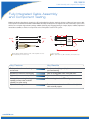
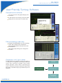
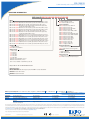
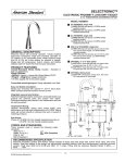
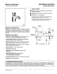
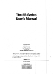
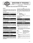
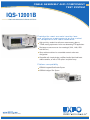
CABLE ASSEMBLY AND COMPONENT
TEST SYSTEM
IQS-12001B
R&D AND MANUFACTURING—OPTICAL
Provides the most accurate insertion loss
and reflectance measurements on the market
for components and cable assemblies
High-sensitivity, mandrel-free reflectance measurements down to
–75 dB, meeting requirements for the most demanding FTTH applications
Simultaneous measurement on four wavelength (1310, 1490, 1550
and 1625 nm)
Open architecture allows for customizable controls and remote
configuration
Compatible with simplex, duplex, multifiber, bundle, hybrid and fanout
cable assemblies, as well as PLC splitters and planar arrays
Platform compatibility
IQS-600 Integrated Qualification System
IQS-500 Intelligent Test System
www.EXFO.com
Telecom Test and Measurement
IQS-12001B
Cable Assembly and Component Test System
Fully Integrated Cable Assembly
and Component Testing
Maximize production throughput for insertion loss (IL) and mandrel-free reflection testing for all types of fiber-optic interconnect cable
and component assemblies with the IQS-12001B Cable Assembly and Component Test System. This fast and accurate system comes
with the most complete single-software package available, delivering truly integrated testing for simplex, duplex, multifiber, hybrid and
fanout fiber assemblies, as well as for components such as PLC splitters used in FTTx systems.
1m
RL
RL + IL
RL + IL
1m
PLC
splitter
RL
RL
ORL + IL + length
Simplex, duplex, multifiber and fanout, with or without hybrid connectors.
(RL = reflectance; IL = insertion loss)
Component testing.
(ORL = optical return loss; RL = reflectance; IL = insertion loss)
Key Features
Key Benefits
Turnkey software for manufacturing
environments
Ready-to-use box (plug and play) to start
your manufacturing
Mandrel-free reflectance measurement
Ideal for non-bendable and/or multimode fibers
Highest reflectance sensitivity: –75 dB
Optimized for FTTx-component qualification
Automated four-wavelength testing
capability and one-meter resolution
capability for splitter testing
Faster testing time for all FTTx configurations
Optical switch integration
Fast and automated tests for multifiber and/or hybrid
cable assembly support
www.EXFO.com
IQS-12001B
Cable Assembly and Component Test System
System overview
The IQS-12001B system features a loss test module (IQS-3250/3250B), optional optical switches and a software package that
integrates and manages test sequences, the database and its results, as well as the peripherals such as bar code reader, label printers
and foot switches used in production environments.
1
1
2
Loss and reflectance measurements
The IQS-3250/3250B Loss Test Module is based on advanced time-domain technology with a wide-aperture integrating cavity
detector. The module’s internal monitoring channel ensures IL measurement accuracy while its internal reflectance reference
significantly improves multimode and singlemode reflectance measurement performance; in singlemode assembly, it also accounts
for the effects of Rayleigh backscattering in each measurement. Combined with EXFO’s advanced detection electronics and
algorithms, the IQS-3250/3250B provides highly accurate mandrel-free reflectance measurements for even the most difficult-totest APC connectors.
2
Customizable modular architecture
The IQS-12001B’s unique architecture allows you to add and remove modules to meet your testing needs. Mix and match
different wavelength combinations, test singlemode and multimode cable assemblies, and add switches to convert your simplex
configuration into a multifiber test system—thanks to the system’s unified software and powerful database, which protect your
valuable production data.
Supported accessories
Label printer
Bar code reader
Foot switch
www.EXFO.com
IQS-12001B
Cable Assembly and Component Test System
User-Friendly Turnkey Software
Comprehensive software
On-screen instructions with graphical display of the
connections
IL and reflectance live monitoring in the main window
Display of the last 100 results in a real-time chart
Post-processing made easy
Integrated, centralized database to save and manage
results, and to generate reports and statistics
Direct integration with bar code reader, foot switch
and label printers
Label printing utility, allowing users to design their
own labels
Customize it to fit your needs
The IQS-12001B comes with DLL interfaces that enable you
to create your own applications and remotely control your
system. These system-level commands ensure smooth,
efficient application creation without compromising the
system’s measurement accuracy and speed. A simple Visual
Basic demo is provided to help you get started with your own
application.
EXFO GUI
Your SW application
EXFO DLL control
IQS-12001B Cable
Assembly and
Component Test System
www.EXFO.com
IQS-12001B
Cable Assembly and Component Test System
Best Performance in the Industry
Test faster, increase your productivity
Cable assembly testing
Insertion loss and reflectance measurements on four wavelengths in
ten seconds flat
Mandrel-free reflectance measurement
Capability to measure singlemode reflectance (discreet reflection)
down to –75 dB, meeting the requirements of even the most
demanding FTTH applications
Component testing (singlemode only, through DLL interfaces)
One sequence for insertion loss, reflectance, optical return loss and
fiber length measurements for all wavelengths
Mandrel-free measurement with one-meter resolution
Accurate, repeatable and flexible
EXFO has developed an innovative detector assembly for the IQS-12001B.
Using wide-aperture integrating cavity packaging, the detector has many
properties that make it ideal for interconnect testing. The wide aperture allows
it to be used for simplex and multifiber connectors. Because it uses integrating
cavity technology, connector alignment is less critical and polarization
dependence is negligible. The end result is increased accuracy, repeatability
and flexibility.
Integrating cavity diagram.
Combining an integrating cavity with a detector and the right diameter input
port provides a major advantage: power measurements are independent of the
fiber’s numerical aperture, ferrule polish (PC or APC) and alignment, since the
cavity scatters all incident light, with the same average power reaching the
detector. Integrating cavity technology is a built-in feature of the two detectors
used with the IQS-12001B Cable Assembly and Component Test System,
the IQS-3250/3250B Loss Test Module and the IQS-9403 Loss Meter.
Calibration verification tool
Reflectance referencing can also be achieved through the CKT-30 Singlemode Reflectance Reference module. Using the IQS-12001B’s
reflectance verification wizard, you can perform a step-by-step verification of your system’s reflectance calibration. As long as it is within
≤ 0.5 dB to that of the CKT-30, you know your system meets calibration specifications and don’t need to send it to EXFO for verification—
avoiding unnecessary downtime.
www.EXFO.com
IQS-12001B
Cable Assembly and Component Test System
Configure Your System for Optimal Performance
The IQS-12001B Cable Assembly Test System is available in two configurations: Standard and High-Throughput. The Standard
configuration includes only the minimal hardware necessary to get the job done. It keeps costs in check, while providing fast and
accurate measurements in a user-friendly format.
The High-Throughput (HT) configuration minimizes the handling required, reducing the overall testing time and increasing the
productivity. This mode of operation is particularly well-suited to hybrid assembly and/or multiwavelength testing. The IQS-12001B can
accommodate additional switch ports and loss meters, enabling hybrid assemblies to be tested in one sequence. External optical
switches can be controlled by the IQS-12001B GPIB interface for test applications requiring more than 32 channels.
The IQS-12001B lets you dedicate switch ports to specific connector types, which avoids having to disconnect the launch fiber, saving
valuable setup time. For example, with a 1x32 switch, you can dedicate ports 1 to 24 to MTP connectors (male and female), ports 25
to 28 to MT-RJ connectors (male and female), and still have room for FC, ST, SC and MU connectors. Depending on the device under
test (DUT), the system uses the appropriate port.
Standard Configuration
High-Troughput Configuration
Simplex
Simplex
MTJ1
MTJ1
OUT
FC
FC
IN
IQS-3250
IQS-3250
Loss Test Module
Loss Test Module
IQS-9100
IN
IQS-9403
1X2
Optical Switch
Loss Meter
With an additional loss meter and a 1x2 optical switch, hybrid
simplex assemblies can be efficiently tested. The two master test
jumpers and detectors are configured for the different connectors
of the hybrid assembly.
Multifiber Connector
Multifiber Connector
MTJ1
MTRJ
SC
MTJ2
IN
Basic configuration for testing simplex
and multifiber bundles.
OUT
MTJ1
OUT
MTRJ
OUT
Male
IN
IN
MTJ2
Female
IQS-3250
Loss Test Module
IQS-9100
1X2
Optical Switch
Basic configuration for testing multifiber
connectors such as MTP and MT-RJ.
IQS-3250
Loss Test Module
IQS-9100
1X2
Optical Switch
By doubling the number of switch ports, the system can be
configured to accept both male and female multifiber connectors.
The end result is faster and simpler testing in a single sequence.
Standard and High-Throughput configurations are also available for testing bundle, duplex and multifiber to fanout assemblies.
www.EXFO.com
IQS-12001B
Cable Assembly and Component Test System
SPECIFICATIONS a
FTB-85102 Singlemode b (1310/1550 nm)FTB-8510-12Singlemode b (1490/1625 nm)
TestingGigabit
time d Ethernet
(s)
<6
<6
Ports
Two 10/100Base-T
Two 10/100Base-T
Cable assembly length (m)
1.8 to 1500
1.8Ethernet
to 1500
and one Gigabit
e LC
Insertion
loss
measurement uncertainty
± 0.03 e
± 0.03
Connector
types
RJ-45 (ISO 8877)
RJ-45 (ISO 8877)
and
Insertion
measurement
stability g (dB) 10/100
< 0.005
Connect loss
speed
(Mb/s)
10/100/1000< 0.005
Reflectance
−30 to −75
−30 to −75
Duplex moderange (dB)
Full/half-duplex
Full/half-duplex
Reflectance measurement uncertainty (dB)auto-negotiation
±1 (−30 to −70)
±1 (−30 to −70)
auto-negotiation
Maximum port capacity (Mb/s)
200 (bidirectional)
2000 (bidirectional)
Ethernet testing
RFC 2544 ±2.2/±1.7 (−70 to −75)
RFC 2544 ±1.7 (−70 to −75)
RFC 1242
RFC 1242
Reflectance measurement repeatability h (dB)
±0.1 (−30 to −65)
±0.1 (−30 to −65)
±0.2 (−65 to −70)
±0.2 (−65 to −70)
±0.4 (−70 to −75)
±0.5 (−70 to −75)
Wavelengths (nm)
Output channels
Test method
1310/1550
Up to 32 channels
End-to-end/bidirectional
1490/1625
Up to 32 channels
End-to-end/bidirectional
Multimode c
FTB-8510-2
<6
Two 10/100Base-T
and two
1.8 to 500
f and LC
± 0.07
RJ-45 (ISO
8877)
< 0.028
10/100/1000
−10 to −50
Full/half-duplex
± 1.2 (−10 to –30)
auto-negotiation
± 1.5 (−30 to –40)
2000 (bidirectional)
± 1.6 (−40 to –43)
RFC 2544
± 2.9 (−43 to –50)
RFC 1242
± 0.2 (−10 to –30)
± 0.4 (−30 to –40)
± 0.6 (−40 to –43)
± 1.8 (−43 to –50)
850/1300
Up to 32 channels
End-to-end/bidirectional
Notes
a. Calculated and measured with the following considerations:
• Based on recommended procedure for ORL measurements
• The FOA-300 series’ uncertainty is included in all uncertainty values
• Although tests are possible with other fiber-optic adapters, these specifications are only valid with the FOA-300 series
• Cable assemblies < 1.8 m can be tested using a non-reflective termination
• With 15 minute warm-up time
b. For SMF-28 fiber. At 23 ºC ± 1 ºC in High-Sensitivity Reflectance mode with no switch.
c. At 850 nm and 1300 nm. For 62.5/125 µm fibers. At 23 °C ± 1 °C, after 30 minutes warmup. Switch module connectorized with FC/PC connectors.
Uncertainty due to launching conditions not included.
d. Calculation and storage time for simplex, dual-wavelength IL/reflectance end-to-end measurements (Standard Reflectance Sensitivity mode, 500 meter range);
does not include referencing and connection time.
e. For simplex measurements using FOA-322 adapter. Uncertainty for MTP to MTP, MT-RJ to MT-RJ, MTP to fanout and MT-RJ to fanout is ± 0.06 dB
(reported with a level of confidence of 95 %). This does not include uncertainties due to connector, connector adapter or switch PDL.
f. For simplex measurement using FOA-322 adapter. Uncertainty for MTP to MTP, MT-RJ to MT-RJ, MTP to fanout and MT-RJ to fanout is ± 0.08 dB
(calculated for a level of confidence of 95 %). Does not include uncertainties due to connector, connector adapter or uncertainties due to mode dependence of the switch.
g. For a stable connection, over 15 minutes, at constant temperature.
h. For a stable connection, over 10 measurements.
GENERAL SPECIFICATIONS
Communication interfaces
General-purpose interface bus (GPIB)
Ethernet (10/100 Base-T)
RS-232
Temperature
Operating
0 °C to 40 °C
Storage
−40 °C to 60 °C
Relative humidity
80 % maximum, non-condensing
(32 °F to 104 °F)
(−40 °F to 140 °F)
Laser Safety
21 CFR 1040.10
IEC 60825-1:2001
CLASS 1 LASER PRODUCT
CLASS 1 LASER PRODUCT
Standard Accessories
Expansion units as required, user guide, certificate of compliance, custom report, label generator, IQS-12001B software and EUI-89 FC narrow key connector.
www.EXFO.com
IQS-12001B
Cable Assembly and Component Test System
ORDERING INFORMATION
IQS-12001B-XX-XX-X-XX-XX-XX-XX-XX-XX-XX
Additional Loss Meter
00 = Without additional loss meter
PM01 = With one additional loss meter
Model
IQS-12001B-05-S5-B = IQS-605P, 1310/1550 nm, IL/RL, optional switch 9/125 µm, APC connector
IQS-12001B-05-S6-B = IQS-605P, 1490/1625 nm, IL/RL, optional switch 9/125 µm, APC connector
IQS-12001B-05-S7-B = IQS-605P, 1490 nm, IL/RL, optional switch 9/125 µm, APC connector
IQS-12001B-05-S8-B = IQS-605P, 1310/1550 and 1490/1625 nm, IL/RL with 1x2 optical switch,
optional switch 9/125 µm, APC connector
IQS-12001B-10-S5-B = IQS-610P, 1310/1550 nm, IL/RL, optional switch 9/125 µm, APC connector
IQS-12001B-10-S6-B = IQS-610P, 1490/1625 nm, IL/RL, optional switch 9/125 µm, APC connector
IQS-12001B-10-S7-B = IQS-610P, 1490 nm, IL/RL, optional switch 9/125 µm, APC connector
IQS-12001B-10-S8-B = IQS-610P, 1310/1550 and 1490/1625 nm, IL/RL with 1x2 optical switch,
optional switch 9/125 µm, APC connector
IQS-12001B-05-S1-C = IQS-605P, 850/1300 nm, IL only, optional switch 50/125 µm, PC connector
IQS-12001B-05-S1-D = IQS-605P, 850/1300 nm, IL only, optional switch 62.5/125 µm, PC connector
IQS-12001B-05-S2-C = IQS-605P, 850/1300 nm, IL/RL, optional switch 50/125 µm, PC connector
IQS-12001B-05-S2-D = IQS-605P, 850/1300 nm, IL/RL, optional switch 62.5/125 µm, PC connector
IQS-12001B-10-S1-C = IQS-610P, 850/1300 nm, IL only, optional switch 50/125 µm, PC connector
IQS-12001B-10-S1-D = IQS-610P, 850/1300 nm, IL only, optional switch 62.5/125 µm, PC connector
IQS-12001B-10-S2-C = IQS-610P, 850/1300 nm, IL/RL, optional switch 50/125 µm, PC connector
IQS-12001B-10-S2-D = IQS-610P, 850/1300 nm, IL/RL, optional switch 62.5/125 µm, PC connector
Connector Adapter
FOA-316 = Ultra-low reflection SMA 906
FOA-322 = Ultra-low reflection FC
FOA-328 = Ultra-low reflection DIN 47256
FOA-332 = Ultra-low reflection ST
FOA-340 = Ultra-low reflection HMS-0, HFS-3
FOA-354 = Ultra-low reflection SC
FOA-376 = Ultra-low reflection HMS, HFS-10/AG
FOA-384 = Ultra-low reflection HMS-10/HP, HFS
FOA-392 = Ultra-low reflection MTP
FOA-393 = Ultra-low reflection MT-RJ
FOA-396 = Ultra-low reflection E-2000
FOA-397 = Ultra-low reflection LX.5
FOA-398 = Ultra-low reflection LC
FOA-399 = Ultra-low reflection MU
FOA-3000 = Adapter for BFA-3000
Hard Disk
00 = Standard hard disk
RHD = RAID 1 second hard drive
Reflectance Reference
00 = Without reflectance reference
CKT-30 = With reflectance reference singlemode
Channel Count
00 = Without switch
1-02 = 1x2 switch
1-04 = 1x4 switch
1-12 = 1x12 switch
1-24 = 1x24 switch
1-32 = 1x32 switch
- Singlemode switch with FC/APC connector
- Multimode switch with FC/PC connector
- Other connectors available: contact EXFO for special order
GPIB Card
00 = Without GPIB card
I3 = GPIB master slave/card
Short Component
00 = Without short component measurement option
SCM = With short component measurement option
Example: IQS-12001B-10-S5-B-RHD-FOA-322-I3-SCM
Optional Accessories
FIP-400-USB2-DUAL: Video fiber inspection probe with USB 2.0 converter and software.
FOA-U12: Universal 1.25 mm ferrule
FOA-U25: Universal 2.5 mm ferrule
EXFO Corporate Headquarters > 400 Godin Avenue, Quebec City (Quebec) G1M 2K2 CANADA Tel.: 1 418 683-0211 Fax: 1 418 683-2170 [email protected]
Toll-free: 1 800 663-3936 (USA and Canada) www.EXFO.com
EXFO America
EXFO Europe
EXFO Asia
EXFO China
3701 Plano Parkway, Suite 160
Omega Enterprise Park, Electron Way
151 Chin Swee Road, #03-29 Manhattan House
No. 88 Fuhua, First Road, Central Tower, Room 801
Futian District
Beijing New Century Hotel Office Tower, Room 1754-1755
No. 6 Southern Capital Gym Road
Plano, TX 75075 USA
Chandlers Ford, Hampshire S053 4SE ENGLAND
SINGAPORE 169876
Shenzhen 518048 P. R. CHINA
Tel.: 1 800 663-3936
Tel.: +44 2380 246810
Tel.: +65 6333 8241
Tel.: +86 (755) 8203 2300
Fax: 1 972 836-0164
Fax: +44 2380 246801
Fax: +65 6333 8242
Fax: +86 (755) 8203 2306
Beijing 100044 P. R. CHINA
Tel.: +86 (10) 6849 2738
Fax: +86 (10) 6849 2662
EXFO is certified ISO 9001 and attests to the quality of these products. This device complies with Part 15 of the FCC Rules. Operation is subject to the following two conditions: (1) this device may not cause harmful interference, and (2) this device must accept any interference
received, including interference that may cause undesired operation. EXFO has made every effort to ensure that the information contained in this specification sheet is accurate. However, we accept no responsibility for any errors or omissions, and we reserve the right to modify
design, characteristics and products at any time without obligation. Units of measurement in this document conform to SI standards and practices. In addition, all of EXFO’s manufactured products are compliant with the European Union’s WEEE directive. For more information, please
visit www.EXFO.com/recycle. Contact EXFO for prices and availability or to obtain the phone number of your local EXFO distributor.
For the most recent version of this spec sheet, please go to the EXFO website at http://www.EXFO.com/specs
In case of discrepancy, the Web version takes precedence over any printed literature.
SPIQS12001B.7AN
© 2008 EXFO Electro-Optical Engineering Inc. All rights reserved.
Printed in Canada 08/02