1
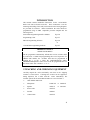
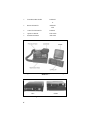
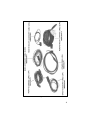
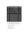
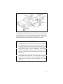
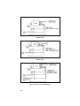
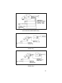
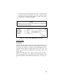
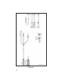
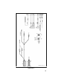
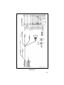
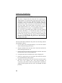
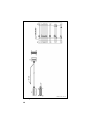
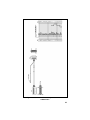
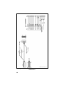
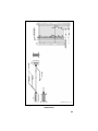
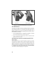
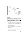
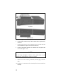
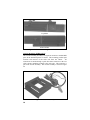
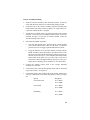
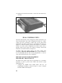
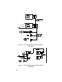
LBI-38901E
Installation Manual
Orion™ Mobile Radio
ericssonz
TABLE OF CONTENTS
INTRODUCTION............................................................................ 3
UNPACKING AND CHECKING EQUIPMENT ............................. 3
PLANNING THE INSTALLATION................................................ 6
EQUIPMENT REQUIRED .............................................................. 8
INSTALLATION IN VEHICLES POWERED BY LIQUEFIED
(LP) GAS......................................................................................... 9
INSTALLATION............................................................................. 9
RUNNING CABLES............................................................... 9
Power Cable.................................................................... 12
Accessory Cable.............................................................. 13
Ignition Sense................................................................. 20
Control Cable (Remote Mount Only) .............................. 21
CONTROL UNIT MOUNTING (REMOTE APPLICATIONS
ONLY) ........................................................................... 21
SPEAKER D2LS1F............................................................... 26
MICROPHONE HANGER AND/OR HOOKSWITCH
MOUNTING ......................................................................... 26
RADIO MOUNTING AND FINAL HOOK-UP..................... 27
Front Mount ................................................................... 27
Remote Mount Installation.............................................. 29
Cassette Mounting (EURO Only).................................... 30
Cassette Assembly Mounting .......................................... 31
DUAL CONTROL UNITS............................................................. 34
PREINSTALLATION PROGRAMMING PROCEDURE
-- FRONT MOUNT ........................................................ 34
PREINSTALLATION PROGRAMMING PROCEDURE
-- REMOTE MOUNT..................................................... 36
INSTALLATION PROGRAMMING FOR FRONT MOUNT
DUAL CONTROL UNITS.............................................. 38
INSTALLATION INSTRUCTIONS FOR REMOTE MOUNT
DUAL CONTROL UNITS.............................................. 39
DUAL RADIO UNITS..................................................................... 43
This manual is published by Ericsson Inc., without any warranty. Improvements and changes
to this manual necessitated by typographical errors, inaccuracies of current information, or
improvements to programs and/or equipment, may be made by Ericsson Inc., at any time and
without notice. Such changes will be incorporated into new editions of this manual. No part of
this manual may be reproduced or transmitted in any form or by any means, electronic or
mechanical, including photocopying and recording, for any purpose, without the express
written permission of Ericsson Inc.
Copyright© October 1993 Ericsson GE Mobile Communications Inc.
2
INTRODUCTION
This manual contains installation instructions for the Orion Mobile
Radio Unit and associated accessories. These instructions cover the
mounting and cabling of the radio; interconnection and wiring diagrams
are provided for reference. Before installation the radio should be
programmed using an IBM compatible personal computer and the
following items:
Serial/Flash Programming Interface Module
TQ3370
Programming Cable
TQ3377
EDACS Programming Software
TQ3374
or
Conventional Programming Software
TQ3367
IMPORTANT NOTICE
ORION UHF MOBILES
The PC programmer automatically defaults the receiver oscillator shift
to position No. 2. When field programming the receive frequencies for
ORION UHF mobiles, the oscillator shift must be programmed to
position No. 1 or No. 3. Enter the CONVENTIONAL and/or
TRUNKED FREQUENCY SET screen of the PC programmer and set
the values in the “OS” column to “1” or “3”.
UNPACKING AND CHECKING EQUIPMENT
Carefully unpack the radio and identify each item in the shipping
container as listed below. If damage has occurred to the equipment
during shipment, file a claim with the carrier immediately. The
available options for the Orion Mobile Radio are covered in Table 1.
•
Orion Mobile Radio Unit
•
Microphone
D2MC3W
or D2MC3Z
•
Speaker
D2LS1F
or D2LS1H
•
Power Cable
D2CE1V
•
Fuse Kit
D2PD1J
•
Control Cable
D2CE1Y
3
•
Front Mount Bracket Kit
D2MA3N
or
•
Remote Mount Kit
D2MA3R
with
•
Control Unit Mount Kit
D2MA3J
•
Operator's Manual
LBI-38888
•
Installation Manual
LBI-38901
Figure 1 - Orion Mobile Radio Components And Mounting
Hardware
USA
EURO
Figure 2 - Rear View Of Radios
4
Figure 3 - Cables
5
Table 1 - Orion Mobile Radio Optional Accessories
Option
D2AN1M
D2AN1L
D2AN1R
D2CE1V
D2CE1W
D2CE1X
D2CE1Y
D2CE1Z
D2CE5R
D2CE5S
D2CE5T
D2CE5U
D2CE5V
D2CE5W
D2CE5Z
D2CE7A
D2CE7B
D2CE7C
D2LS1F
D2LS1H
D2MA3J
D2MA3N
D2MA3R
D2MA3W
D2MA3X
D2MC3W
D2MC3Z
D2MK3E
D2MK3F
D2MN1A
D2PD1J
Description
900 MHz, 1/4 Wave Whip Antenna
800 MHz 1/4 Wave Whip Antenna
VHF/UHF, 1/4 Wave Whip Antenna
Power Cable, 7.5 M
Accessory Cable, Front Mount
Accessory Cable, Rear Mount
Control Cable, Remote Mount, 5.5 M
Accessory Cable, Front Mount EURO
Extended Option Accessory Cable Front Mount
EXT Option Control Cable, Remote Mount, 5.5 M
EXT Option Accessory Cable, Remote Mount
EXT Option Accessory Cable, Front Mount, EURO
Control Cable, Remote Mount, EURO, 5.5 M
EXT Option Control Cable, Remote Mount, 5.5 M
Dual Control Cable, Remote Mount, 9.0 M
Dual Radio Cable, Remote Mount, 2.0 M
Dual Control Cable, Remote Mount, 9.0 M, EURO
Dual Radio Cable, Remote Mount, 2.0 M, EURO
Speaker, GE Label
Speaker, ERICSSON Label
Mounting Bracket Kit, Remote Control Unit
Mounting Bracket Kit, Front Mount Radio
Mounting Bracket Kit, Remote Mount Radio
Mounting Bracket Kit, Remote Mount Radio, EURO
Cassette Mounting Bracket Kit, Front Mount, EURO
Microphone, GE Label
Microphone, Ericsson Label
Keycap Kit, SCAN Control Unit
Keycap Kit, SYSTEM Control Unit
Microphone Hanger
Transmit Fuse Holder Kit, 20/30A (USA Only)
Part Number
19B801182P3
19B209568P5
19B209568P6
19B802622P1
19B802554P1
19B802554P6
19B802554P3
19B802554P11
19B802554P2
19B802554P4
19B802554P7
19B802554P12
19B802554P13
19B802554P14
19B802554P9
19B802554P10
19A149590P1
19A149590P11
344A4584G2
19B802672P1
19B802673P1
19B802672P1
19B852366P1
19C852359P101
19C852359P102
7141414G2
19A149701G2
PLANNING THE INSTALLATION
Figure 4 provides an example of a typical mobile radio installation.
Before starting, plan the radio installation carefully so that it will be:
•
•
•
•
•
•
•
6
safe for the operator and passengers
convenient for the operator to use
neat
protected from water damage
easy to service
out of the way of auto mechanics
out of the way of passengers
Figure 4 - Typical Installation (Remote Mount Shown)
It is suggested that the radio be installed by one of the many authorized
General Electric Service Stations located throughout the United States.
These experienced service stations can provide a proper radio
installation and make any final adjustments that may be needed.
WARNING
•
Vehicular Electronics-Electronic fuel injection systems, electronic
anti-skid braking systems, electronic cruise control systems, etc.,
are typical of the types of electronic devices which may be prone
to malfunction due to the lack of protection from radio frequency
energy present when a radio is transmitting. If the vehicle
contains such equipment, consult the dealer to determine if such
electronic equipment will perform normally when the radio is
transmitting.
•
For passenger safety, mount the radio securely so that the unit
will not break loose in the event of a collision. This is especially
important in station wagons, vans and similar type installations
where a loose radio could be extremely dangerous to the vehicle
occupants.
7
EQUIPMENT REQUIRED
The equipment required for installing the Orion Mobile Radio is listed
below:
•
Crimping Tool for fuse holder
•
Electric drill for drilling mounting holes
•
Drills and circle cutters as follows:
No. 31 (1/8-inch) drill
No. 27 (9/64-inch) drill
5/8-inch drill or circle cutter
3/4-inch circle cutter, hole saw or socket punch
•
Phillips and flat-blade screwdrivers
•
POZIDRIV driver
•
No. 20 Torx driver
Torx is a registered trademark of CAMCAR Division TEXTRON, Inc.
POZIDRIV is a registered trademark of Phillips International Company.
CAUTION
•
Be careful to avoid damaging some vital part (fuel tank,
transmission housing, etc.) of the vehicle when drilling mounting
holes. Always check to see how far the mounting screws will
extend below the mounting surface before installing.
•
If pilot holes must be drilled, remove all metal shavings from
drilling holes before installing screws.
8
INSTALLATION IN VEHICLES POWERED
BY LIQUEFIED (LP) GAS
Radio installation in vehicles powered by liquefied petroleum gas
with the LP gas container in the trunk or other sealed-off space
within the interior of the vehicle must conform to the National Fire
Protection Association Standard NFPA 58 which requires that:
•
Space containing radio equipment shall be isolated by a seal from
the space containing the LP gas container and its fittings.
•
Outside filling connections shall be used for the LP gas container.
•
The LP gas container space shall be vented to the outside of the
vehicle.
INSTALLATION
RUNNING CABLES
To assure the feasibility of the planned cable routings, it is suggested
that the cables be run before mounting the radio. The Orion mobile
radio may be installed as a Front Mount, Remote Mount or Cassette
Mount. The type of mount, the application and the options to be
installed should be considered when planning the cable runs. Figures 512 provide Interconnection Diagrams for typical installations. Figures
5-12 should be referenced throughout this manual and throughout the
installation.
Be sure to leave some slack in each cable going to the radio so that the
radio may be pulled out for servicing with the power applied and
antenna attached. Coil any surplus cables and secure them out of the
way. Try to route the cables away from locations where they will be
exposed to heat (exhaust pipes, mufflers, tailpipes, etc.), battery acid,
sharp edges or mechanical damage or where they will be a nuisance to
automobile mechanics, the driver or passengers. Keep wiring away from
electronic computer modules, other electronic modules and ignition
circuits to help prevent interference to these components and radio
equipment.
In addition, try to utilize existing holes in the firewall, trunk wall and
the channels above or beneath doors. Channels through door and
window columns that are convenient for running cables may also be
used, unless rigid or flexible conduit is to be installed for cable runs.
9
Figure 5 - Front Mount Basic Accessory Interconnections (USA
Models Only)
Figure 6 - Front Mount Basic Accessory Interconnections (EURO
Models Only)
Figure 7 - Front Mount Extended Option Accessory
Interconnections (USA Models Only)
10
Figure 8 - Front Mount Extended Option Accessory
Interconnections (EURO Models Only)
Figure 9 - Remote Mount Basic Accessory Interconnections (USA
Models Only)
Figure 10 - Remote Mount Basic Accessory Interconnections (EURO
Models Only)
11
Figure 11 - Remote Mount Extended Option Accessory
Interconnections (USA Models Only)
Figure 12 - Remote Mount Extended Option Accessory
Interconnections (EURO Models Only)
Power Cable
The USA power cable (19B802622P1) consists of a red lead A+ and a
black lead A- connected to a molded 2-pin power connector and
supplied with ring terminals. The EURO power cable also consists of a
red lead A+, a black lead A- and is terminated with ring terminals, but it
is connected to P1 of the Accessory Cable or P1 of the Control Cable (in
remote applications). To install the power cable:
1.
Drill a 5/8-inch hole in the firewall for the cable run and insert the
rubber grommet. Run the cable through this grommet to the battery
location. Secure the cable at several locations within the engine
compartment to prevent possible damage to cable.
2.
Strip back the insulation approximately 3/8 of an inch from the end
of the black lead. Slide one of the large heat shrink sleeves onto the
wire and crimp a battery ring terminal onto this lead. Heat shrink
the sleeve over the crimp connection. Connect the black lead
directly to the battery negative (-) or ground frame member.
3.
Cut off 12-18 inches from the red lead. Strip back the insulation
approximately 3/8 of an inch on each end of the wires. Insert the
12
wire ends into the small openings at the end of each fuse holder
section and crimp a fuse connector to each wire. Prepare the other
end of the short wire in the same manner as in Step 2 and connect
to the positive (+) terminal of the battery.
NOTE
Do not install fuse into fuse holder until installation is completed and
all connections have been checked.
Figure 13 - Power Cable 19B802622P1 (USA Only)
Accessory Cable
Front Mount
The Basic Accessory Cable, at one end, consists of the basic accessories
connector (P3), the speaker connector (P2) and the ignition sense lead.
At the other end is plug P1. P1 connects to the Option/Remote Control
Connector (ORCC) which is mounted on the back of the radio. The
EURO Accessory Cable also contains the red and black leads of the
Power Cable.
NOTE: The EURO ORCC is the opposite gender from the USA ORCC.
The Extended Option Accessory Cable is the same as the Basic Cable
but with the addition of the Extended Option Plug (P4). See Figures 1417.
13
(19B802554, Sh.1, Rev. 19)
Figure 14 - USA Front Mount Standard Accessory Cable
19B802554P1
14
(19B802554, Sh.9, Rev. 19)
Figure 15 - EURO Front Mount Standard Accessory Cable
19B802554P11
15
(19B802554, Sh.2, Rev. 19)
Figure 16 - USA Front Mount Extended Option Accessory Cable
19B802554P2
16
(19B802554, Sh.10, Rev. 19)
Figure 17 - EURO Front Mount Extended Option Accessory Cable
19B802554P12
17
Remote Mount
The Basic Accessory Cable, at one end, consists of the basic accessories
connector (P3) and the speaker connector (P2). At the other end is the
plug P1. P1 will connect to the Option Connector (OPT) which is
mounted on the back of the Radio Interface Adapter (RIA). The
Extended Option Accessory Cable is the same as the Basic Cable but
with the addition of the Extended Option Plug (P4). See Figures 18 and
19.
(19B802554, Sh.5, Rev. 19)
Figure 18 - Remote Mount Standard Accessory Cable 19B802554P6
18
(19B802554, Sh.6, Rev. 19)
Figure 19 - Remote Mount Extended Option Accessory Cable
19B802554P7
19
Ignition Sense (All Applications)
NOTE
•
The radio as shipped from the factory has the "ignition sense"
feature disabled. As such the radio will be powered ON or OFF as
determined by the front panel ON/OFF/VOLUME control only
(assuming A+ and A- are connected). If it is desired to enable the
"ignition sense" feature, open top cover of radio and remove shield
from logic PWB. Slide switch SW601 from position 3-2 to 1-2.
Replace shield and top cover. Be sure to apply correct torque to
screws holding top cover in place. See Maintenance Manual.
•
The "Accessory" point should drop to ZERO volts when cranking
the engine and return to +12 volts after the engine is started. If a
point is chosen that drops to a voltage between zero and +12 volts,
the radio may execute a power-up cycle several times during start
up. It is recommended that the terminal be measured with a
voltmeter to be sure it shuts off (goes to zero volts) during the
cranking of the engine.
The fuse holder must be attached to the yellow sense lead along with the
ring terminal as follows:
1.
Cut the yellow sense lead approximately 6-12" from the end that
will be connected to the power source.
2.
Strip the insulation from each end of the short lead and from the
end of the long lead at least 3/8".
3.
Insert the stripped end of the long lead and one end of the short lead
into the narrow end of each fuse holder half.
4.
Crimp the leads in the fuse holder halves with a crimping tool.
5.
Insert the 3 amp fuse into one end of the fuse holder and join the
two fuse holder halves firmly together.
6.
Attach the ring terminal to the end of the short lead and connect
this lead to the ignition "ON" sense point [preferably an
"Accessory" point (in the vehicle fuse panel) that is switched on
when the vehicle ignition switch is in the ACCESSORY and RUN
positions].
20
CAUTION
Certain problems may be encountered when accessory equipment is
connected to the ignition or accessory lines of the vehicle, where these
lines may have large filter capacitors and a leakage path present. If
the radio does not turn off within a reasonable amount of time after
the ignition is turned off, first try a different accessory or ignition
sense pick up point in the vehicle. Many vehicles have more than one
circuit that is switched by the ignition switch, and one may be
available that does not have large filter capacitors or a leakage path
present.
If a different pickup point cannot be found, then add a 470-ohm, 1watt resistor from the ignition sense pick point to ground. This will
discharge the capacitor(s) or reduce the leakage voltage to a low
value. Current drain through this resistor will be minimal (less than
0.03A) when the ignition is switched on.
Control Cable (Remote Mount Only)
The Control Cable is used to connect the Control Unit (through the RIA)
to the Radio Transceiver in remote applications. Plug P2, at one end,
connects to the Remote Control Cable Connector (RCCC) which is
mounted on the back of the RIA. The Ignition Sense wire is also part of
P2. The other end of the Control Cable (P1) connects to the ORCC
which is mounted on the back of the radio. P1 of the EURO Control
Cable also contains the Power Cable leads. See Figures 20-23.
CONTROL UNIT MOUNTING (REMOTE
APPLICATIONS ONLY)
1.
Using the bracket as a template, mark and drill the mounting holes.
Be sure to leave enough room at the rear of the control unit for the
cable connector. Refer to Figure 24 for control unit mounting
bracket installation.
2.
Secure the mounting bracket using the four No. 10 x 3/4 selftapping screws supplied (use No. 10 x 1-1/2 if needed.).
3.
Secure the control unit to the bracket with the two 1/4-20 x 5/8 hex
head screws and lock washers provided.
21
(19B802554, Sh.3, Rev. 19)
Figure 20 - USA Remote Control Cable 19B802554P3
22
(19B802554, Sh.4, Rev. 19)
Figure 21 - USA Remote Extended Option Control Cable
19B802554P4
23
(19B802554, Sh.11, Rev. 19)
Figure 22 - USA Extended Options Remote Control Cable
19B802554P13
24
(19B802554, Sh.12, Rev. 19)
Figure 23 - EURO Extended Options Remote Control Cable
19B802554P14
25
Top Mount
Bottom Mount
Figure 24 - Control Unit Mounting Bracket Installation
SPEAKER D2LS1F
The speaker kit includes the speaker, mounting bracket and connecting
cable. Mount the speaker so it is directed to the operator but does not
present a hazard in the event of an accident. The speaker may be
mounted on the lower edge of the instrument panel, the firewall or above
the windshield in some trucks.
1.
Use the mounting bracket as a template for locating the mounting
holes and mount the speaker as shown in Figure 25.
2.
Refer to the applicable installation procedures for connection of the
speaker to the accessory cable.
MICROPHONE HANGER AND/OR HOOKSWITCH
MOUNTING
The microphone hanger or hookswitch should be mounted in a location
convenient to the operator where it will not interfere with the safe
operation of the vehicle or be a hazard to the vehicle passengers. The
hanger or hookswitch is designed to be mounted with the open end of
the mounting button slot pointed upward. Use the hanger or hookswitch
as a template to mark and drill the mounting holes. Mount the hanger
or hookswitch with the self-tapping screws provided.
26
Figure 25 - Speaker Mounting
RADIO MOUNTING AND FINAL HOOK-UP
Front Mount
Typically the bracket shown in Figure 26 is used for Front Mount
applications. The bracket can be mounted so that it is either above or
below the radio for the user's convenience. The bracket pictured in
Figure 24 can also be used for Remote Mount application but is not
recommended for 110 watt VHF radios or 100 watt UHF radios.
The following instructions are for a Front Mount installation using the
bracket shown in Figure 26.
1.
Use the supplied mounting bracket as a template to locate the
position for each of the drill holes. Be sure to leave enough room at
the front and rear of the radio for cable connections. Drill No. 27
(9/64) pilot holes.
2.
Mount bracket with four 1/4"-14 x 3/4" sheet metal screws (use
1/4"-14 x 1-1/2" screws if needed).
3.
Place radio into mounting bracket and secure with the four M4 x 10
mm hex head screws, M4 flat washers and M4 lock washers
supplied. No. 20 Torx.
4.
Connect antenna coaxial cable to antenna connector (TNC).
5.
Connect front mount accessory cable connector P1 to the
Option/Remote Control Connector (ORCC) and secure with the two
captive screws in the connector to the radio.
27
Top Mount
Bottom Mount
Figure 26 - Mounting Bracket Installation
6.
Connect front mount accessory cable connector P2 to speaker cable
connector.
7.
Connect power cable to power connector on rear of radio unit and
secure with the two captive screws to the radio unit.
8.
Connect microphone connector to connector on front panel and
secure with captive screw.
NOTE
Do not torque microphone connector screw greater than 2 in-lb.
Alternatively, finger tight plus 1/4 turn is acceptable.
9.
If there are no other accessory connections, tie back plug P3 to main
cable.
10. Recheck all connections before inserting fuse into transmit fuse
assembly.
28
Remote Mount Installation
The bracket shown in Figure 27 is used for Remote Mounting (USA
Only). In some applications the bracket shown in Figure 26 can also be
used for Remote Mounting. The following instructions are for a Remote
Mount installation using the bracket shown in Figure 27.
1.
Using the bracket as a template, mark and drill the mounting holes
using a No. 27 drill. Be sure to leave enough room at the rear of
the radio unit for the cable connections.
2.
Secure the Mounting bracket using four 1/4"-14 x 3/4" sheet metal
screws (use 1/4"-14 x 1" if needed.) The bracket can be used
mounted so that it is either above or below the radio for the user's
convenience.
3.
Slide the radio unit into the bracket by aligning bracket guides with
grooves on each side of radio (rear of radio should be inserted first).
Slide radio back until screw holes in front of bracket align with
screw holes in side of radio. See Figure 27.
4.
Secure radio to the bracket with two M4 x 10 mm socket head
screws provided.
5.
Connect antenna coaxial cable to antenna connector (TNC).
6.
Connect remote control cable connector P1 to the ORCC connector
on the radio unit and secure with the two captive screws.
7.
Connect other end of remote control cable to the remote control
cable connector (RCCC) on the remote control unit.
8.
Connect remote mount accessory cable connector P1 to the option
connector (OPT) on control unit. Then connect the speaker to
connector P2 and accessory connector P3 to any options
(hookswitch, etc.). If connector P3 is not used, insulate and tie back
to main cable.
9.
Recheck all connections and cables. Insert fuse into transmit fuse
assembly.
29
Top Mount
Bottom Mount
Figure 27 - Remote Mounting Bracket Installation
Cassette Mounting (EURO ONLY)
The cassette mounting assembly is designed to mount in a standard DIN
space in the instrument panel or console. This mounting permits rapid
insertion and removal of the radio unit from the vehicle. All
connections are made through a quick disconnect connector at the rear
of the cassette mounting assembly to the radio unit. This connector is
part of the cassette assembly. The cassette assembly is shown in Figure
28.
Figure 28 - Cassette Assembly
30
Cassette Assembly Mounting
1.
Insert the cassette assembly in the mounting location. Secure the
cables with the sheet metal screws and retaining straps provided.
2.
Secure the back of the cassette assembly using the mounting stud
(located at the back of the cassette assembly), No. 6 flat washer, No.
6 split lock washer and No. 6 wing nut.
3.
Several tabs are located on the top, bottom and sides of the cassette
assembly. These tabs are conveniently located near the front of the
assembly and may be bent out as needed to further secure the
cassette assembly to the vehicle.
4.
Next install the Handle Assembly:
a.
Turn the radio upside down. Remove the two small machine
screws on the bottom of the radio, near the front. Use upward
pressure on screws to engage captivated threads for removal.
b.
Using the machine screws and flat washers provided with the
handle assembly, attach the handle to the bottom of the radio.
The two holes on the handle should align with the two holes on
the radio created by step (a). Once installed, the rubber handle
should rotate freely from over top of the radio to just out in
front of the control unit (approximately 90 degrees). Be sure to
torque the two mounting screws within 6.5 to 8.25 in/lb limits.
5.
Connect the antenna coaxial cable to the cassette mounting
assembly rear connector.
6.
Connect the Power leads and the Ignition Sense leads as described
in previous sections. See Figure 29.
7.
Connect the speaker cable connector P2 to the speaker and the basic
accessory connector P3 to the following options (if used, see Figure
29):
Option
Plug & Pin
Ext. Hookswitch
P3-3 (HOT)
P3-6 (GND)
Foot Switch
P3-5 (HOT)
P3-2 (GND)
Horn Relay
P3-1 (HOT)
P3-4 (GND)
31
(19C852366, Sh.2, Rev.1)
Figure 29 - Cassette Assembly Schematic Diagram
32
8.
Connect the extended option accessory plug P4 to the following
options (if used, see Figure 29):
•
•
•
•
•
•
•
Mobile Data Terminal
Public Address (External Amplifier)
External Microphone
External Tone Encoder
External Tone Decoder
Output (User Defined)
Input (User Defined)
CAUTION
Refer to accessory manual supplement for details regarding the
extended options listed above. DO NOT CONNECT DIRECTLY TO
A PC OR DATA TERMINAL. DAMAGE COULD RESULT!!!
9.
With the handle assembly in the UNLOCKED position (out in front
of the control unit), insert the radio into the cassette assembly.
Slide the radio into the cassette assembly until the back of the radio
meets the back of the cassette assembly.
NOTE
Caution should be used while engaging the radio in the cassette the
first few times until the cabling in the cassette mount assembly has had
an opportunity to work into its permanent location. To insure proper
first time engagement, the following procedure should be used:
Insert radio into cassette mount opening and slide in until you feel
some spring resistance. Holding the handle, jiggle the radio a bit to
give it a chance to find the connectors. Then engage the radio handle
in the sheet metal hooks which protrude from the lower corners of the
cassette mount casing. Rotate the handle upward to fully engage the
radio. See Figure 30. DO NOT FORCE THE CONNECTOR
ENGAGEMENT portion of the travel.
If the radio does not go in using this procedure, a large flat blade
screwdriver may be used to re-position the 37 pin connector slightly to
assist the first time engagement.
33
10. Recheck all connections and cables. Insert fuse into transmit fuse
assembly.
Figure 30 - Handle Assembly In LOCKED Position
DUAL CONTROL UNITS
The Dual Control feature can be configured for either front mount or for
remote mount Radio Units. Each configuration provides for a Main
Control Unit and an Auxiliary Control Unit. In the front mount
configuration, the Main Control Unit is on the Radio Unit itself (see
Figure 33), with the Auxiliary Control Unit located in a convenient
location. In remote mount configuration the Main Control Unit is
typically located in the vehicle cab, with the Auxiliary Control Unit
located in a convenient location (see Figure 34).
All Radio Units and Control Units in the Dual Control Unit
configuration MUST BE PROGRAMMED prior to final installation.
It is recommended that the units be first programmed at a Service
Center, then transferred to the user’s installation.
PRE-INSTALLATION PROGRAMMING
PROCEDURE --FRONT MOUNT
The Radio and Control Units must be programmed in a sequential
procedure, in order to provide each Control Unit with the proper
identification code.
1.
34
Configure the ORION Front Mount Radio with the
PC
Programming Assembly, as shown in Figure 31, Step 1. Program
the radio with the following files:
Personality Name
Radio Code
<USERPERS>
OGXXXXX
ADI Code
<SAME>
Radio Unit ID
<SAME>
ORION Keypad File <CUBMAP>
ORION CU ID
2.
CU B
User’s personality file
Latest radio code file
(G13 or later vintage)
Keypad definition for
Control Unit B
Must be Control Unit B
Now configure the Front Mount Radio and the Auxiliary Control
Unit together with the PC Programming Assembly, as shown in
Figure 31, Step 2. Program this configuration with the following
files:
Personality Name
<USERPERS>
Radio Code
<SAME>
ADI Code
<SAME>
Radio ID
<SAME>
ORION Keypad Files <CUAMAP>
ORION CU ID
CU A
User’s personality file
Keypad definition for
Control Unit A
Must be Control Unit A
Note that the Main Control Unit has ID “B” and the Auxiliary Control
Unit has ID “A” in this configuration.
Figure 31 - ORION Dual Control Unit PC Programming
Configuration
35
PRE-INSTALLATION PROGRAMMING
PROCEDURE -- REMOTE MOUNT
The Radio and Control Units must be programmed in a sequential
procedure, in order to provide each Control Unit with the proper
identification code.
1.
Configure the ORION Remote Mount Radio and Auxiliary Control
Unit with the PC Programming Assembly, as shown in Figure 32,
Step 1. Program the radio with the following files:
Personality name
Radio Code
<USERPERS>
OGXXXXX
ADI Code
<SAME>
Radio Unit ID
<SAME>
ORION Keypad File <CUBMAP>
ORION CU ID
2.
CU B
User’s personality file
Latest radio code file
(G13 or later vintage)
Keypad definition for
Control Unit B
Must be Control Unit B
Now configure the Remote Mount Radio, the Main Control Unit,
and the Auxiliary Control Unit together with the PC Programming
Assembly, as shown in Figure 32, Step 2. Program this
configuration with the following files:
Personality Name
Radio Code
ADI Code
Radio ID
ORION Keypad File
<USERPERS>
<SAME>
<SAME>
<SAME>
<CUAMAP>
ORION CU ID
CU A
User’s personality file
Keypad definition for
Control Unit A
Must be Control Unit A
Note that the Main Control Unit has ID “A” and Auxiliary Control Unit
has ID “B” in this configuration.
36
Figure 32 - ORION Dual Control Unit PC Programming
Configuration Remote Mount
37
INSTALLATION INSTRUCTIONS FOR FRONT
MOUNT DUAL CONTROL UNITS
The Dual Control Unit feature is configured such that only one control
unit can be used for Extended Option accessories. All Extended Option
accessories are connected through the Main Control Unit.
1.
Referring to Figure 33, run the Dual Control Cable (19B802554P9)
between locations for the Radio Unit and Auxiliary Control Unit. Be
sure to locate the P2/P3 connector assembly at the Radio Unit.
2.
After installing Radio Unit mounting hardware in the normal
fashion, connect the Dual Control Cable connector (P3) to the Radio
Unit. Tighten the two jackscrews on P3. Next, connect the
Accessory Cable (19B802554P1 or P2) Connector (P1) to the Dual
Control Cable Connector (P2), and tighten the jackscrews on P2.
Connect the power cable, and install Radio Unit in mounting
bracket.
3.
After installing the Auxiliary Control Unit in the normal fashion,
connect the Dual Control Cable (P1) to Auxiliary Control Unit, and
tighten jackscrews.
4.
Connect the Remote Mount Accessory Cable (19B802554P6) to the
Auxiliary Control Unit.
5.
A yellow Ignition Sense lead is provided on the Dual Control Cable
and the Front Mount Accessory Cable. If the “Ignition Sense”
feature is enabled on the Radio Unit, it is necessary to connect only
one of the yellow leads provided, whichever is convenient. Tape
back the unused yellow lead (See Page 20 for details).
6.
Install the Speakers in convenient locations near the Radio Unit and
Auxiliary Control Unit.
7.
Install a relay (19A149299P1) from the kits supplied at a location
near the leads from each speaker. For mounting, use the #8 X 3/4”
sheetmetal screw and nutplate supplied with each kit.
8.
At a convenient point cut one of the wires in each of the 2-wire
speaker cables, spread the leads, and strip the ends. Crimp a 1/4”
tab receptacle to each end.
9.
Radio Unit Speaker: Connect the lead nearest the speaker to Pin
87A of the relay. Connect the lead nearest the connector to Pin 30
of the relay. Connect the connector to the Accessory Cable P2
(Refer to Figure 33).
10. Auxiliary Control Unit Speaker: Connect the lead nearest the
speaker to Pin 87 of the relay. Connect the lead nearest the
38
connector to Pin 30 of the relay. Connect the connector to the
Accessory Cable P2 (Refer to Figure 33).
11. For each relay: Connect a #18 AWG black wire between the relay,
Pin 85 and Accessory Cable P3-1 (labeled “OUT2” on the
schematic diagrams in the service manual). Use a 1/4” tab
receptacle on the relay side and mating Molex connector and pins
on the accessory cable side. Connect the mating Molex connector to
the Accessory Cable P3 when finished (Refer to Figure 33).
12. For each relay: Connect a #18 AWG red wire to the relay, Pin 86.
Cut to length, and connect to the 1 amp fuse holder supplied. Use
crimp on connectors supplied. Connect the other side of the 1 amp
fuse holder to A+ battery source or vehicle A+ fuse block. Use #18
AWG red wire and ring lug supplied., if needed (See Figure 33).
13. Check dual control operation, using operator’s manual as a test
guide. In the PC programming software, make sure the “DUAL
CONTROL SPEAKER is programmed ACTIVE LOW.
Figure 33 - ORION Dual Control Unit Front Mount/Remote Mount
Installation Configuration
INSTALLATION INSTRUCTIONS FOR REMOTE
MOUNT DUAL CONTROL UNITS
1.
Referring to Figure 34, run the Remote Control Cable
(19B802554P3 or P4) between locations for the Radio Unit and
Main Control Unit.
39
2.
Run the Dual Control Cable (19B802554P9) between locations for
the Radio Unit and Auxiliary Control Unit. Be sure to locate the
P2/P3 connector assembly at the radio unit.
3.
After installing the Radio Unit in the normal fashion, connect the
dual control cable connector (P3) to the Radio Unit. Tighten the two
jackscrews on P3. Next, connect the Remote Control Cable
connector (P1) to the Dual Control Cable connector (P2), and
tighten jackscrews on P2.
4.
After installing the Main Control Unit in the normal fashion,
connect the Remote Control Cable (P2) to the Main Control Unit,
and tighten jackscrews.
5.
After installing the auxiliary control unit in the normal fashion,
connect the Dual Control Cable (P1) to the Auxiliary Control Unit,
and tighten jackscrews.
6.
Connect the accessory cable (19B802554P6) to the Auxiliary
Control Unit. Connect either the accessory cable (19B802554P6) or
the extended option accessory cable (19B802554P7) to the Main
Control Unit, as appropriate.
7.
A yellow ignition sense lead is provided on each control cable. If
the “Ignition Sense” feature is enabled on the Radio Unit, it is
necessary to connect only one of the yellow leads provided,
whichever is convenient. Tape back the unused yellow lead. See
page 20 for details.
8.
Install the speakers in convient locations near each control unit.
9.
Install a relay (19A149299P1) from the kits supplied at a location
near the leads from each speaker. For mounting use the #8 X 3/4”
sheetmetal screw and nutplate supplied with each kit.
10. At a convenient point cut one of the wires in each of the 2-wire
speaker cables, spread the leads, and strip the ends. (Crimp a 1/4”
tab receptacle to each end.
11. Main Control Unit Speaker: Connect the lead nearest the speaker
to Pin 87 of the relay. Connect the lead nearest the connector to Pin
30 of the relay. Connect connector to the accessory cable P2 (Refer
to Figure 34).
12. Auxiliary Control Unit Speaker: Connect the lead nearest the
speaker to Pin 87A of the relay. Connect the lead nearest the
connector to Pin 30 of the relay. Connect the connector to accessory
cable P2 (Refer to Figure 34).
40
13. For Each Relay: Connect a #18 AWG black wire between the relay,
Pin 85 and accessory cable P3-1 (labeled “OUT2” on schematic
diagrams in the service manual). Use a 1/4” tab receptacle on the
relay side and a mating Molex connector and pins on the accessory
cable side. Connect the mating Molex connector to the accessory
cable P3 when finished (Refer to Figure 34).
14. For Each Relay: Connect one end of a #18 AWG red wire to the
relay, Pin 86. Cut the lead to length, and connect the other end to
the 1 amp fuse holder supplied. Use crimp on connectors supplied.
Connect the other side of the 1 amp fuse holder to the A+ battery
source or a vehicle A+ fuse block. Use a #18 AWG red wire and a
ring lug supplied, if needed (Refer to Figure 34).
15. Check dual control operation, using the operator’s manual as a test
guide. In the PC programming software, make sure the “DUAL
CONTROL SPEAKER is programmed ACTIVE HIGH.
Figure 34 - ORION Dual Control Unit Remote Mount/Remote
Mount Installation Configuration
41
(19B802554, Sh.7, Rev. 19)
Figure 35 - Remote Mount Dual Control Cable 19B802554P9
42
DUAL RADIO UNITS
The Dual Radio feature can be configured either for two remote mount radio
units or one front mount unit and one remote mount unit. In remote mount
configurations the Control Unit is typically located in the vehicle cab, with
the Radio Units located side-by-side in vehicle trunk. In front/remote mount
configurations the front mount unit is located in the vehicle cab, with the
remote mount unit located in a convenient location nearby. The
remote/remote mount configuration is the preferred installation, since a
separate control unit is required to program the remote unit in a front/remote
mount configuration.
The following Dual Radio Unit configurations are not allowed:
1.
Any configuration using a DIN cassette mount.
2.
Any installation where Extended Options are required from both Radio
Units. Extended Options are supported in one Radio Unit only.
PRE-INSTALLATION PROGRAMMING
PROCEDURE
All Radio Units in the Dual Radio configuration MUST BE
PROGRAMMED prior to final installation. It is recommended that the units
be first programmed at a Service Center, then transferred to the user's
installation.
These configurations provide for a Master Radio Unit and a Slave Radio
Unit. In the remote/remote mount configuration, the Master Radio Unit is
always the radio most directly connected to the Control Unit. In the
front/remote mount configuration, the Master Radio Unit is always the front
mount radio. Extended Options are allowed only in the Master Radio Unit.
Programming each radio is straightforward, except that one radio is
programmed as a Master, and one as a Slave.
1.
Decide which Radio Unit shall be the Master Unit. Configure the radio
for programming as shown in the applicable service section manual.
2.
In the "Multi-Radio" field of the PC programmer, select "Master".
3.
Program unit normally.
purchased.
4.
Now configure the "Slave" Radio Unit for programming. Be sure to use
the programming configuration for remote mount, and supply the
required control unit, if for a front/remote mount dual radio
configuration.
Include Extended Option features, if
43
5.
In the "Multi-Radio" field of the PC programmer, select "Slave". Radio
Units are now ready for vehicle installation.
6.
Program normally. Do not include Extended Option features.
INSTALLATION INSTRUCTIONS FOR
FRONT/REMOTE MOUNT DUAL RADIO
CONFIGURATION.
1.
Plan the mounting locations of the two Radio Units. Note that the
maximum cable length allowed between the two radios is two meters.
Referring to Figure 36, run Dual Radio Cable (19B802554P10) between
locations for Master and Slave Radio Units. Be sure to locate the P2/P3
connector assembly at the Master Radio Unit.
2.
After installing Master Radio Unit mounting hardware, connect the
Dual Radio Cable Connector (P3) to the Master Radio Unit. Tighten
the two jackscrews on P3. Next connect the Accessory Cable
(19B802554P1 or P2) Connector (P1) to the Dual Radio Cable
Connector (P2), and tighten to jackscrews on P2.
3.
Connect Microphone and Accessories. Refer to Accessory Installation
Manual for proper connection of Accessories.
4.
Connect Power Cable, and Antenna, then install Master Radio Unit in
mounting bracket.
5.
Connect "IGN A+" lead, if option is desired. Be sure internal Switch
SW601 is set properly. Refer to Page 20 of this manual for details.
6.
After installing Slave Radio Unit in its mounting hardware, connect
Dual Radio Cable (P1), and tighten jackscrews. Be sure SW601 setting
on Slave Radio Unit is same as for Master Radio Unit. Connect Power
Cable and Antenna to Slave Radio.
7.
Check Dual Radio operation, using Operator's Manual as test guide.
INSTALLATION INSTRUCTIONS FOR
REMOTE/REMOTE MOUNT DUAL RADIO
CONFIGURATION.
1.
44
Plan the mounting locations of the two Radio Units. Note that the
maximum cable length allowed between the two radios is two meters.
Referring to Figure 37, run Dual Radio Cable (19B802554P10) between
locations for Master and Slave Radio Units. Be sure to locate the P2/P3
connector assembly at the Master Radio Unit.
2.
After installing Master Radio Unit mounting hardware, connect the
Dual Radio Cable Connector (P3) to the Master Radio Unit. Tighten
the two jackscrews on P3.
3.
Next route the Remote Control Cable (19B802554P3 or P4) between
Control Head and Master Radio locations. After installing Control
Head, connect Remote Control Cable Connector (P2) to Control Head.
4.
Connect "IGN A+" lead, if option is desired. Be sure internal Switch
SW601 on Master Radio is set properly. Refer to Page 20 of this
manual for details.
5.
Connect Accessory Cable (19B802554P6 or P7) Connector (P1) to
Control Head.
6.
Connect Microphone and Accessories. Refer to Accessory Installation
Manual for proper connection of Accessories.
7.
Now connect Remote Control Cable Connector (P1) to the Dual Radio
Cable Connector (P2), and tighten to jackscrews on P2.
8.
Connect Power Cable, and Antenna, then install Master Radio Unit in
mounting bracket.
9.
After installing Slave Radio Unit in its mounting hardware, connect
Dual Radio Cable (P1), and tighten jackscrews. Be sure SW601 setting
on Slave Radio Unit is same as for Master Radio Unit. Connect Power
Cable and Antenna to Slave Radio.
10. Check Dual Radio operation, using operator's manual as test guide.
45
Figure 36 - Orion Dual Radio Front Mount Installation
Configuration
Figure 37 - Orion Dual Radio Remote Mount Installation
Configuration
46
(19B802554, Sh.8, Rev. 19)
Figure 38 Dual Radio Control Cable (19B802554P10)
47
Ericsson Inc.
Private Radio Systems
Mountain View Road
Lynchburg, Virginia 24502
1-800-528-7711 (Outside USA, 804-528-7711)
Printed in U.S.A.