1
Advanced Force Measurement
Model 9840
Digital Process Monitor
Interface, Inc. 7401 E. Butherus Dr. Scottsdale, Arizona 85260 USA
Tel: (480) 948-5555, Fax: (480) 948-1924
I N T E R F AC E M O D E L 9 8 4 0 V E R 6 . 0 . 2
CONTENTS
CONTENTS .................................................................................................................................................. 1
INTRODUCTION ........................................................................................................................................ 4
QUICK START ............................................................................................................................................ 6
RUN MODE .................................................................................................................................................. 9
ITEM BUTTON ................................................................................................................................................ 10
TARE BUTTON ............................................................................................................................................... 10
RESET BUTTON .............................................................................................................................................. 11
VIEW BUTTON ............................................................................................................................................... 11
ESC BUTTON .................................................................................................................................................. 11
UNIT BUTTON ................................................................................................................................................ 12
SETUP MODE SUMMARY...................................................................................................................... 13
SETUP MODE ............................................................................................................................................ 14
ENTERING NUMERICAL DATA........................................................................................................................ 15
ENTERING ALPHANUMERIC DATA ................................................................................................................. 15
>USER DATA ENTRY ..................................................................................................................................... 15
>>Base Area Ch A/B ............................................................................................................................... 15
>>Base Length......................................................................................................................................... 15
>ANALOG OUTPUT ........................................................................................................................................ 15
>SENSOR SELECT........................................................................................................................................... 17
SENSOR DELETE ............................................................................................................................................ 18
>CALIBRATION .............................................................................................................................................. 18
>>Cal Check............................................................................................................................................ 19
>>Cal by mV/volt (2-Point or 6-Point).................................................................................................... 19
>>Cal by Masses or Torque (2-Point or 5-Point) ................................................................................... 19
>>Cal by Shunt Val ................................................................................................................................. 20
>>Counts per Inch................................................................................................................................... 20
>LIMITS ......................................................................................................................................................... 20
>SYSTEM OPTIONS ........................................................................................................................................ 21
>>Printer Baud........................................................................................................................................ 21
>>Auto Identify........................................................................................................................................ 21
>>Auto Zero Ch A/B................................................................................................................................ 21
>>Com Address ....................................................................................................................................... 22
>>Com Baudrate ..................................................................................................................................... 22
>>Com Line Feed .................................................................................................................................... 22
>>Retain Tare.......................................................................................................................................... 22
>>RS232 EOT Char ................................................................................................................................ 22
>DISPLAY OPTIONS ....................................................................................................................................... 22
>>Filter Select ......................................................................................................................................... 22
>>Decimals Ch A/B................................................................................................................................. 23
>>Count By Ch A/B ................................................................................................................................. 23
>>Second Line......................................................................................................................................... 23
>>Filter Window ..................................................................................................................................... 23
REMOTE OPERATION ........................................................................................................................... 24
DIGITAL INPUTS ............................................................................................................................................. 24
USB Driver ............................................................................................................................................... 24
MODEL 9840
PG 1
PUB. 2856-16
I N T E R F AC E M O D E L 9 8 4 0 V E R 6 . 0 . 2
Communications Settings ......................................................................................................................... 25
Communications Format.......................................................................................................................... 25
RS232 RUN MODE COMMAND SUMMARY....................................................................................... 25
RS232 RUN MODE COMMANDS........................................................................................................... 26
HELLO COMMAND (H)................................................................................................................................... 26
QUESTION MARK COMMAND (?) ................................................................................................................... 26
FRONT PANEL DISPLAY COMMAND (F) ......................................................................................................... 27
Front Panel View Command (FV)............................................................................................................ 27
Front Panel Set Command (FS) ............................................................................................................... 27
Front Panel Alternate Command (FA)..................................................................................................... 27
Front Panel Pointer Control to Line 1 (F1) ............................................................................................. 27
Front Panel Pointer Control to Line 2 (F2) ............................................................................................. 28
VALUE COMMAND (V) FOR ONE OR BOTH CHANNELS .................................................................................... 28
PRINT COMMAND (P)..................................................................................................................................... 29
RESET TARE, PEAK, VALLEY OR POSITION COMMAND (R)............................................................................ 29
FREEZE DISPLAY COMMAND (X) ................................................................................................................... 30
TEXT DISPLAY COMMAND (T)....................................................................................................................... 30
RS232 SETUP MODE COMMAND SUMMARY................................................................................... 31
RS232 SETUP MODE COMMANDS....................................................................................................... 32
USER DATA ENTRY COMMAND (U) ............................................................................................................... 32
User Data View Command (UV).............................................................................................................. 32
User Data Area Command (UA) .............................................................................................................. 32
User Data Length Command (UL) ........................................................................................................... 32
ANALOG OUTPUT COMMAND (A).................................................................................................................. 33
Analog Output View Command (AV) ....................................................................................................... 33
Analog Output Set Command (AS) ........................................................................................................... 33
SENSOR COMMAND (S).................................................................................................................................. 33
Sensor View Channel A or B Command (SA or SB)................................................................................. 33
Sensor View Command (SV)..................................................................................................................... 34
Sensor Select Command (SS).................................................................................................................... 34
Sensor Delete Command (SD).................................................................................................................. 34
CALIBRATION COMMAND (C) ........................................................................................................................ 35
Calibration Check Command (CC) .......................................................................................................... 35
Calibration Begin Command (CB)........................................................................................................... 35
Calibration Escape Command (CE)......................................................................................................... 37
Calibrate by Millivolt-Per-Volt Command for One Point (CV) ............................................................... 37
Calibrate by Millivolt-Per-Volt Command for Six Points (CMV6) .......................................................... 37
Calibrate by mV/V Mass and Volt Commands (CMVM and CMVV) ....................................................... 37
Calibrate by mV/V Torque and Volt Commands (CMVT and CMVV)..................................................... 38
Calibrate by Masses Command (CM) ...................................................................................................... 39
Calibrate by Masses Point Command (CMP) .......................................................................................... 40
Calibrate by Torque Command (CT) ....................................................................................................... 41
Calibrate by Torque Point Command (CTP) ........................................................................................... 41
Calibrate by Shunt Command (CS) .......................................................................................................... 42
Calibrate Counts-Per-Inch Command (CI).............................................................................................. 42
LIMITS COMMAND (L) ................................................................................................................................... 43
Limit View Command (LiV)...................................................................................................................... 43
Limit Set Command (LiS) ......................................................................................................................... 43
Limit Setup Escape (LE)........................................................................................................................... 44
Limit Reset Command (LiR) ..................................................................................................................... 45
SYSTEM OPTIONS COMMAND (O) .................................................................................................................. 45
MODEL 9840
PG 2
PUB. 2856-16
I N T E R F AC E M O D E L 9 8 4 0 V E R 6 . 0 . 2
Option View Command (OV).................................................................................................................... 45
Option Printer Baudrate Command (OP) ................................................................................................ 45
Option Auto-Identify Command (OI)........................................................................................................ 46
Option Auto-Zeroing Command (OZ) ...................................................................................................... 46
Option Com Address Command (OA) ...................................................................................................... 46
Option Com Baudrate Command (OB) .................................................................................................... 47
Option Linefeed Command (OL) .............................................................................................................. 47
Option Tare Retain Command (OT)......................................................................................................... 47
Option End of Transmission Character (OE)........................................................................................... 47
DISPLAY OPTIONS COMMAND (D) ................................................................................................................. 48
Display View Command (DV) .................................................................................................................. 48
Display Filter Command (DF) ................................................................................................................. 48
Display Decimal Command (DD) ............................................................................................................ 48
Display Count By Command (DC) ........................................................................................................... 49
Display Second Line Command (D2) ....................................................................................................... 49
Display Second Line Text (DT) ................................................................................................................ 49
Display Filter Window Commands (DW)................................................................................................. 49
SYSTEM CALIBRATION MODE ........................................................................................................... 51
APPENDIX A -- MODEL 9840 SPECIFICATIONS .............................................................................. 52
APPENDIX B -- CABLES AND CONNECTORS................................................................................... 55
LOAD CELL CONNECTORS ............................................................................................................................. 55
SERIAL PORT CONNECTOR ............................................................................................................................. 55
DIGITAL I/O CONNECTOR .............................................................................................................................. 56
CHART REC. CONNECTOR .............................................................................................................................. 56
USB CONNECTOR .......................................................................................................................................... 57
PRECISION SHUNT CALIBRATION RESISTORS ................................................................................................. 58
Under the copyright laws, this publication may not be reproduced or transmitted in any
form, electronic or mechanical, including photocopying, recording, storing in an
information retrieval system, or translating, in whole or part, without the prior consent of
Interface, Inc. Copyright January 8, 2008 all rights reserved.
MODEL 9840
PG 3
PUB. 2856-16
I N T E R F AC E M O D E L 9 8 4 0 V E R 6 . 0 . 2
INTRODUCTION
The Model 9840 is a CE compliant and versatile precision instrument intended for the
digital readout of strain gage sensors such as load cells and torque cells. Optical
encoders are also supported.
Here is a quick listing of its features:
•
Full bi-polar 6 digit display (±999,999) using two line, 20 character, vacuum
fluorescent display for clear, precise indication of measured quantities and limit status.
•
No knobs or dials. No internal jumpers. All adjustment and calibration is done using
user-friendly front panel menus. Keylock option to prevent accidental or unauthorized
changes to the unit’s setup.
•
Measure load and gross weight in pounds, kilograms, Newtons, PSI, MegaPascals,
kilo-pounds, kilo-Newtons, metric tons, mV/V, or grams. User defined base area for
PSI and MPa. Tare at any time. The sum of the loads on both channels is also
availabe.
•
Measure torque and gross torque in Pound-Inches, Newton-Meters, Ounce-Inches,
or mV/V. Tare at any time. The sum of the torques on both channels is also availabe.
•
Capture the load peak and valley, display in pounds, kilograms, Newtons, PSI,
MegaPascals, kilo-pounds, kilo-Newtons, metric tons, mV/V, or grams. Reset at any
time.
•
Capture the torque peak and valley, display in in Pound-Inches, Newton-Meters,
Ounce-Inches, or mV/V. Reset at any time.
•
Measure position and velocity with optional encoder input. Display in English units,
metric units, or in percent of a user defined base length. Reset at any time.
•
Four contact closure Limit switches. You can set which signal drives the limit (load,
torque, peak, valley, position, or velocity), normally open / normally closed, set point,
and manual reset (latched) or automatic reset (not latched).
•
Print current readings of load, torque, peak, valley, position, and velocity using the
currently selected units at the touch of one button (optional).
•
Automatic identification of calibrated cells with auto-id option.
•
Calibration for cells using manufacturer’s milli-volt per volt calibration factor, 6 point
mass and milli-volt per volt, 2 or 5 point known mass, 6 point torque and milli-volt per
volt, 2 or 5 point known torque, or internal precision shunt calibration. A back panel
switch allows you to choose between two values used for the shunt calibration so
there is no need to open the unit.
•
Analog output of any signal (load, torque, peak, valley, position, velocity) with user
defined scale factor and offset. Large, buffered ± 10.00 volt output.
MODEL 9840
PG 4
PUB. 2856-16
I N T E R F AC E M O D E L 9 8 4 0 V E R 6 . 0 . 2
•
Remote operation using standard RS232 ASCII command set.
•
Each unit is set up to interact with the InterView software that can save tests, export
data to a spreadsheet, and much more.
•
Back panel digital inputs for tare, peak and valley reset, position reset, and print.
Other functions available as custom programmed options.
MODEL 9840
PG 5
PUB. 2856-16
I N T E R F AC E M O D E L 9 8 4 0 V E R 6 . 0 . 2
QUICK START
This section will help you get your Model 9840 set up and operating in just a couple of
minutes.
The back panel is shown below. You will need to make at least two connections here.
First be sure that the power switch is off (the lower part of the rocker should be pressed
in). Connect the AC power line and plug it in.
MODEL 9840 BACK PANEL
Next connect a load or torque cell to the 9 pin female connector labeled “Load A”. You
should use the cabling supplied with your Model 9840 and Interface load or torque cell. If
you do not have a factory supplied cable see Appendix B for the recommended cell
connection.
You are now ready to turn on the power. Each time power is applied to the Model 9840
you will see a sequence of 6 messages appear on the front display. For example,
MODEL 9840
PG 6
PUB. 2856-16
I N T E R F AC E M O D E L 9 8 4 0 V E R 6 . 0 . 2
#
Message
1
Interface X.Y.Z
This is the version number.
2
Serial # 12345
This is the serial number.
Option # 114236
This is the option number.
3
4
5
Meaning
Last ID A LD90437
The serial number of the load cell on Ch A.
Last ID B TQ12030
The serial number of the torque cell on Ch B
Ch A Max
4.00Lb
Maximum rated load of the sensor on channel A.
Ch B Max
4.00LbI
Maximum rated torque of the sensor on channel B.
Ch A Cal 4.00000 mVv
The mV/V constant used with the load cell on channel A.
Ch B Cal 4.00000 mVv
The mV/V constant used with the torque cell on channel
B.
Note: If either of these sensors was calibrated by 5 –Point
Mass, then 4 mV/V constants will be displayed here.
6
Ch A Exc 5.00 Volt
Excitation voltage used with the load cell on channel A.
Ch B Exc 10.00 Volt
Excitation voltage used with the torque cell on channel B.
Each of these messages will be displayed for about 3 seconds. After that the front display
will start showing the current readings from the sensor.
MODEL 9840 FRONT PANEL
The example above shows that Load A is 0.0000 Lb. The second line of the display
shows text.
To change what item is being displayed press the leftmost button. This will cycle through
the list of items (load A, peak A, valley A, gross A, load B, peak B, valley B, gross B,
channel A+B, pos, velocity, lim). If a torque cell is loaded on either channel, the display
will show torq rather than load for the appropriate channel. Channel A+B will only appear
when both channels are attached to sensors of the same type: load or torque.
MODEL 9840
PG 7
PUB. 2856-16
I N T E R F AC E M O D E L 9 8 4 0 V E R 6 . 0 . 2
The rightmost button will change the units that are being used. Repeated presses of this
button will cycle through the list of units available for the currently displayed item. For
example, with Load A showing you would see Lb, kg, N, PSI, MPa, Klb, kN, t, mV/V,
grams, and then back to Lb. With Torq A, you will see LbI, NM, OzI, and mV/V.
Switching from a load to a torque cell and back will automatically reset Analog, Limit, and
Filter Window settings to zero and/or disabled for that particular channel. See information
under each of these options for details on how they work.
MODEL 9840
PG 8
PUB. 2856-16
I N T E R F AC E M O D E L 9 8 4 0 V E R 6 . 0 . 2
RUN MODE
The Model 9840 has three modes of operation, Run mode, Setup mode, and System
Calibration mode. At power-on it will be in Run mode.
The first line of the display show an item label (Load A), a value (0.0000), and a unit label
(Lb).
The second line of the display can show the status of the 4 contact closure limit switches,
show another display, show text, or be blank. The above example shows text
(“INTERFACE MODEL 9840”).
To change what item is being displayed press the leftmost button. This will cycle through
the list of items (Load A, Peak A, Vall A, Grs A, Load B, Peak B, Vall B, Grs B, Ch A+B,
Pos, Vel, and Limits). If a torque cell is attached rather than a Load Cell, Torq A or B will
replace Load A or B. Channel A+B will only appear when both channels are attached to
sensors of the same type: load or torque.
The rightmost button will change the units that are being used. Repeated presses of this
button will cycle through the list of units available for the currently displayed item. For
example, with Load showing you would see Lb, kg, N, PSI, MPa, Klb, kN, t, mV/V, grams,
and then back to Lb. Torq will show LbI, NM, OzI and mV/V.
MODEL 9840
PG 9
PUB. 2856-16
I N T E R F AC E M O D E L 9 8 4 0 V E R 6 . 0 . 2
The table below summarizes the options. Whether the user sees torque or load for each
channel depends upon the cell type that was calibrated or selected for that channel.
Load A/B
Peak A/B
(Load)
Valley A/B
(Load)
Gross A/B
(Load)
Channel
A+B (Ld)
Torq A/B
Peak A/B
(Torque)
Valley A/B
(Torque)
Gross A/B
(Torque)
Channel
A+B (Tq)
Position
Velocity
Limits
Pounds, Kilograms, Newtons, PSI, MegaPascals, Kilo-Pounds,
Kilo-Newtons, Metric Tons, mV/V, grams.
Pounds, Kilograms, Newtons, PSI, MegaPascals, Kilo-Pounds,
Kilo-Newtons, Metric Tons, mV/V, grams.
Pounds, Kilograms, Newtons, PSI, MegaPascals, Kilo-Pounds,
Kilo-Newtons, Metric Tons, mV/V, grams.
Pounds, Kilograms, Newtons, PSI, MegaPascals, Kilo-Pounds,
Kilo-Newtons, Metric Tons, mV/V, grams.
Pounds, Kilograms, Newtons, PSI, MegaPascals, Kilo-Pounds,
Kilo-Newtons, Metric Tons, mV/V, grams.
Pound-Inches, Newton-Meters, Ounce-Inches, mV/V.
Pound-Inches, Newton-Meters, Ounce-Inches, mV/V.
Pound-Inches, Newton-Meters, Ounce-Inches, mV/V.
Pound-Inches, Newton-Meters, Ounce-Inches, mV/V.
Pound-Inches, Newton-Meters, Ounce-Inches, mV/V.
Inches, Centimeters, Percent of Base Length.
Inches per Minute, Centimeters per Minute.
Shows state of each switch, 1 for on, 0 for off, dash for
disabled, asterisk for source error.
All of these measurements are acquired by the Model 9840 at all times with torque
measurements acquired when a torque cell is attached to a channel and load
measurements acquired when a load cell is attached. The display just selects which
particular item you wish to see and what units are used to display or print this data.
The buttons have the functions indicated by the upper set of labels (Item, Tare, Reset,
View, Esc, Print, Unit). Each of these is described below.
Item Button
The Item button cycles through the list of different items that can be displayed
(Load A, Peak A, Vall A, Grs A, Load B, Peak B, Vall B, Grs B, Ch A+B, Pos, Vel,
Limits). Torq A or B substitutes for Load A or B when appropriate. Use the Unit
button to change the units that are used for the currently displayed item. Ch A+B is
only available when the cells on both channels are of the same type (load or
torque).
Tare Button
The Tare button sets the current load or torque to zero for channel A, channel B,
or channels A and B. A submenu will allow you to select what channel you want
to tare. It does not matter what is being displayed when you press this button.
MODEL 9840
PG 10
PUB. 2856-16
I N T E R F AC E M O D E L 9 8 4 0 V E R 6 . 0 . 2
The load or torque is always reset to zero. A single channel unit will automatically
set Load A or Torque A to zero.
Reset Button
The Reset button brings up a list of things that you might want to set to zero:
If this is a 2-channel unit, the following menu will appear:
> Reset Ch A + Ch B will reset the peak and valley for channels A and B.
> Reset Ch A Only will reset the peak and valley for channel A.
> Reset Ch B Only will reset the peak and valley for channel B.
> Reset Position will reset the position to zero.
> Reset Limits will reset any limits that require manual resetting.
For a single channel unit, the following menu will appear:
> Reset Peak+Vall will reset the peak and valley measurements.
> Reset Peak Only will reset the peak measurement.
> Reset Vall Only will reset the valley measurement.
> Reset Position will reset the position to zero.
> Reset Limits will reset any limits that require manual resetting.
Pressing either the “+” button or the “>“ button will scroll forward through this list.
Pressing either the “-” button or the “<“ button will scroll backward through the list.
Pressing “Enter” will reset the currently displayed item. Pressing “Esc” will return
to Run Mode without resetting anything. Note that all menu lists on the Model
9840 start with the “>“ symbol and that the Esc button will always back out of a
menu without making any changes.
View Button
The View button switches between two virtual displays stored in the memory.
Each of these displays will remember the units you have selected for each item,
and which item is currently being shown. This may save you from scrolling
through the list of items if there are two particular results that you often use. For
instance you might set the display to show Load in Lb, press View, and then set
the display for Peak in PSI. Repeated presses of the View button will now switch
back and forth between Load in Lb and Peak in PSI with a single button push. If
you choose to have the second line show a display, then the View button toggles
between the display currently being activated. The activated display will have a
“>” symbol to the left of it.
Esc Button
In Run Mode, the Esc button will freeze and unfreeze the run mode numerical
display. Press once to freeze the display at the current value. Press again to
return display to actual reading from sensor. See Setup Mode information for the
use of the Esc button during setup.
MODEL 9840
PG 11
PUB. 2856-16
I N T E R F AC E M O D E L 9 8 4 0 V E R 6 . 0 . 2
Print Button
If the Print option is purchased, the Print Button can be used to either print data or
to freeze the display. If the Hold option is purchased, the functionality of the
button is set using the System Setup options. Otherwise, the button can only
control the ability to print data.
In Run Mode, if the System Setup Options Print/Hold button is set to Hold, the
Print button will freeze and unfreeze the run mode numerical display. Press once
to freeze the display at the current value. Press again to return display to actual
reading from sensor. See Setup Mode information for the use of the Esc button
during setup.
If the Print button is set to Print, it will send a set of data to the printer. This will
contain the current readings of load, peak, valley, position, velocity, and limit
status. The units used for printing will be the units last selected on the numerical
display.
The printer must be a serial printer that supports ESC/P protocol. Many Epson
printers with serial ports are known to be compatible.
Appendix B gives the pin assignments on the serial connector.
Unit Button
The Unit button cycles through the list of units that are available for the item that is
currently being displayed.
MODEL 9840
PG 12
PUB. 2856-16
I N T E R F AC E M O D E L 9 8 4 0 V E R 6 . 0 . 2
SETUP MODE SUMMARY
The table below summarizes the setup mode menus. Detailed information about each
individual item is presented in the following sections.
Setup mode
╠══════
║
║
║
╠══════
║
║
╠══════
║
║
╠══════
║
║
║
║
║
║
╠══════
║
║
║
║
╠══════
║
║
║
║
║
║
║
╠══════
║
╚══════
MODEL 9840
>User Data Entry
╠════════
╚════════
>>Base Area Ch A/B
>>Base Length
>Analog Output
╚════════
Source → Units → Full → Zero.
>Sensor Select
╚════════
Channel → Serial Number List → Cal Info.
>Calibration →
╠════════
╠════════
╠════════
╠════════
╚════════
(password access and cell type)
>>Cal Check
>>Cal by mV / volt
>>Cal by Masses or Torque
>>Cal by Shunt
>>Counts / Inch
>Limits
╚════════
Select → NO/NC → Enable →
Source → Units →Set → Trip →
Latch → Reset → Done.
>System Options
╠════════
╠════════
╠════════
╠════════
╠════════
╠════════
╠════════
╚════════
>>Printer Baud
>>Auto Identify
>>Auto Zero Ch A/B
>>Com Address
>>Com Baudrate
>>Com Line Feed
>>Retain Tare
>>RS232 EOT Char
>Display Options
╠════════
╠════════
╠════════
╠════════
╚════════
>>Filter Select
>>Decimals Ch A/B
>>Count By Ch A/B
>>Second Line
>>Filter Window
PG 13
PUB. 2856-16
I N T E R F AC E M O D E L 9 8 4 0 V E R 6 . 0 . 2
SETUP MODE
Setup mode is used to change the setup of the Model 9840. To enter setup mode press
the two end buttons at the same time ( “<“ and “>“ ). The row of four buttons will now
function as indicated by the lower set of labels (Plus, Minus, Enter, and Escape).
If the optional keylock is in the locked position you will see “>Setup is Locked” when you
try to enter setup mode. This prevents accidental or unauthorized changes to the setup of
the unit.
To exit from setup mode and return to run mode press the escape button (Esc). When
you are entering numerical data or selecting options from a sub-menu the escape button
will back you out without making any changes.
The main menu in setup mode contains the following 6 entries which will be described in
detail in the following sections. Note that all main menu items begin with the “>“ symbol
and that all submenu items begin with the “>>“ symbol.
•
•
•
•
•
•
•
> User Data Entry -- allows you to set any common math options such as the base
area used to display load in PSI or the base length used to display position in percent.
> Analog Output -- is used to select the source and scaling for the standard analog
output channel.
> Sensor Select -- lets you manually set which load or torque cell calibration data is
used. If you use auto-id cells you will never need this menu.
> Calibration -- provides access to calibration for cells or optical encoders.
> Limits -- allows you to set the source and options for the 4 contact closure switches.
> System Options -- contains entries to set the printer baud rate, enable or disable
automatic sensor identification, enable or disable automatic load or torque zeroing, set
the serial communications address, baud rate, line feed, and RS232 options, and
choose whether or not to retain the most recent tare value through power down.
> Display Options -- lets you choose the filtering that is applied to the load or torque
measurements, an optional window of data incrementation on which to turn the filter
off, the number of decimal digits that are shown on the display and on the print, the
count by values for channels A and B (1, 2, 5, 10, or 20), and whether the second line
of the display shows the limit switch status, a blank line, another display, or text.
The Plus or Right button ( “+” or “>“ ) will scroll forward through this menu. The Minus or
Left button ( “-” or “<“ ) will scroll backward through this menu. The Enter button selects
the currently displayed menu item. The Esc button will return you to Run Mode.
MODEL 9840
PG 14
PUB. 2856-16
I N T E R F AC E M O D E L 9 8 4 0 V E R 6 . 0 . 2
Entering Numerical Data
At times you will need to enter numerical data into the Model 9840. The method is
consistent in all cases. A number is presented on the left side of the display with an
underline cursor.
•
•
•
•
•
•
•
Left ( “<“ ) moves the cursor left one position. If you are on the leftmost digit a new
zero will be added. Thus 10.000 will become 010.00 where the cursor has moved
from the tens place to the hundreds place.
Right ( “>“ ) moves the cursor right one position. If you are at the far right a new
decimal will be added if there is room. Thus 12.34 will become 12.340 where the
cursor has moved from the tenths to the hundredths place.
Plus ( “+” ) increments the digit above the cursor. Thus 12.34 becomes 13.34. Note
that 9 will “wrap around” to 0.
Minus ( “-” ) decrements the digit above the cursor. Thus 12.34 becomes 11.34.
Note that 0 will “wrap around” to 9.
Plus and Minus (both “+” and “-” at the same time). This will change the sign of the
number. Thus 12.34 becomes -12.34. Note that cursor position does not matter when
you change the sign.
Enter accepts the currently displayed number.
Esc escapes from numerical entry and discards any changes that have been made.
Entering Alphanumeric Data
When entering cell serial numbers, the option of using numbers and/or letters from A to Z
is available. This works in the same way as entering numerical data with the exception
that no decimal point exists in the display.
>User Data Entry
This menu is used to enter numerical constants used by the math options. These
constants are listed in a submenu that works exactly like the main setup mode menu.
Typical items in this submenu are:
>>Base Area Ch A/B
This is the area in square inches that is used to calculate load in pounds per square
inch (PSI) or Mega Pascals (MPa).
>>Base Length
This is the length in inches that is used to calculate position in percent.
>Analog Output
This menu is used to set up the standard analog output. Instead of a submenu there is a
series of selections. Pressing escape at any time will leave the analog output unchanged
and return you to the setup mode main menu. Note that when you change a cell type
(from load to torque or back again) these settings must be reset for the new cell. If the
unit is a 2-channel unit and the Analog Output B option has been enabled, the first option
asks the user for the Analog Output channel. Select A or B. Then begin selecting the
following settings.
MODEL 9840
PG 15
PUB. 2856-16
I N T E R F AC E M O D E L 9 8 4 0 V E R 6 . 0 . 2
1. Source: -- This entry allows you to scroll through a list (using the left/right or
plus/minus buttons) to select the source of the data that will drive the analog output.
The standard list will include load or torque, peak, valley, gross, position, and velocity.
Channel A+B is an option which, if chosen, will appear only if the cells on both
channels are of the same type. Press enter to select the displayed item.
2. Units: -- This entry allows you to scroll through the list of available units for the data
source you have chosen in the previous step.
3. Full -- This entry specifies the value of source data (in the selected units) that will
cause the Model 9840 to output positive full scale analog voltage (+10.0 volts).
4. Zero -- This entry specifies the value of source data (in the selected units) that will
cause the Model 9840 to output zero analog voltage (0.0 volts).
Once you have entered these 4 selections the analog output is setup.
4-20MA Output Option
This option allows the user to output with current (milliamps) rather than voltage. It
operates similarly to Analog Output using the same submenus, but, in this case, the Full
and Zero data entered control the distribution of output in milliamps from the unit given
certain inputs to the cell. Particularly, the number entered for Zero will set the
corresponding input in Lbs to output 12 milliamps (the mid-point between four and twenty
milliamps) and the unit will extrapolate other output values between 4 and 20 milliamps.
If this option is enabled, the following steps will set up the unit: follow the instructions for
Analog Output until "Source:" is displayed. Toggle through until the "Load A" is on the
display. Press the enter button to bring up the "Lb" menu. Press the enter button again
and the "4.0000 Lb Full" menu will be displayed. This is where the maximum Lbs for the
cell should be entered. Press enter and the "0.0000 Lb Zero" menu will be displayed.
This is where the offset from zero (the value in lbs that will give a 12 milliamp) should be
entered. Press the enter button to return to the Analog Output menu and then press the
escape button to return to the normal display.
Example outputs with varying Full and Zero Values (assuming a 4.00 Lb calibrated cell
with 10 V excitation):
1. Full = 4.0000 Lb
Zero = 0.0000 Lb
(Input) Mv/V
(Output) Volt
(Output) MA
4
3
2
1
0
-1
-2
-3
-4
10v
7.5v
5.0v
2.5v
0v
-2.5v
-5.0v
-7.5v
-10.0v
20mA
18mA
16mA
14mA
12mA
10mA
8mA
6mA
4mA
MODEL 9840
PG 16
PUB. 2856-16
I N T E R F AC E M O D E L 9 8 4 0 V E R 6 . 0 . 2
2. Full = 4.0000 Lb
Zero = 4.0000 Lb
(Input) Mv/V
(Output)Volt
(Output) MA
4
3
2
1
0
-1
-2
-3
-4
0v
-2.5v
-5.0v
-7.5v
-10.0v
-10.0v
-10.0v
-10.0v
-10.0v
12mA
10mA
8mA
6mA
4mA
4mA
4mA
4mA
4mA
3. Full = 2.0000 Lb
Zero = 0.0000 Lb
(Input) Mv/V
(Output) Volt
(Output) MA
4
3
2
1
0
-1
-2
-3
-4
10.0v
10.0v
10.0v
5.00v
0v
-5.0v
-10.0v
-10.0v
-10.0v
20mA
20mA
20mA
16mA
12mA
8mA
4mA
4mA
4mA
4. Full = 2.0000 Lb
Zero = 2.0000 Lb
(Input) Mv/V
(Output) Volt
(Output) MA
4
3
2
1
0
-1
-2
-3
-4
10.0v
5.0v
0v
-5.00v
-10.00v
-10.0v
-10.0v
-10.0v
-10.0v
20mA
16mA
12mA
8mA
4mA
4mA
4mA
4mA
4mA
>Sensor Select
This menu is used to manually select load or torque cell calibration data from a list stored
in the Model 9840. When you select this menu on a 2 channel unit, you are asked to
select Channel A or B. The cell serial number of the selected channel is displayed. Use
either the left/right or plus/minus buttons to page through the list. The escape button will
MODEL 9840
PG 17
PUB. 2856-16
I N T E R F AC E M O D E L 9 8 4 0 V E R 6 . 0 . 2
return to the setup mode main menu without changing the cell that is selected. The enter
button will select the currently displayed cell and briefly display the rated load or torque,
last calibration date, and excitation voltage.
To add new cells to this list use the Calibration entry on the setup mode main menu
described below.
If you are using auto-id load cells this menu will allow you to see which cell is selected but
will not allow you to change the selection. This ensures that the correct calibration
information is always used when you use Auto-ID load cells.
If the selected cell is of a different type (load or torque) than that previously displayed on
the channel, the display item and units will change accordingly.
Sensor Delete
The Model 9840 can store calibration data for 25 different cells. To delete a cell from this
list choose “>Sensor Select” from the setup mode main menu. Press the left/right or
plus/minus keys until the serial number of the cell you wish to delete is displayed. (You
may need to shut off auto-id if it is on, see the System Options menu for details). Then
press both the plus and minus keys at the same time. The Model 9840 will ask “Delete
Sensor?” to be sure that you intend to delete this calibration data. Pressing Enter will
delete the cell data from the list. Pressing Escape will return to the cell select without
changing the list.
>Calibration
This menu is used to access all methods of calibration that are supported by the Model
9840. Selecting calibration from the setup mode main menu will bring up a password
entry field. Successful entrance of the password (888) will bring up a submenu which
asks for the cell type. Toggle through either Load or Torque and press enter when
appropriate. Another submenu will appear listing the various types of calibration. This
submenu is used exactly like the main menu. Press left/right or plus/minus to change the
menu item. Press escape to return to the setup mode main menu. Press enter to select
the displayed menu item.
If you are re-calibrating a cell, the Model 9840 will recognize it using either the auto-id or a
manually entered serial number. Any time you overwrite existing cell calibration data you
will first be warned with the “Overwrite Data?” message. Pressing enter will overwrite;
pressing escape will cancel the calibration. Another method of overwriting existing data is
to delete the sensor first and then calibrate.
If a cell with a new serial number (or new auto-id) is calibrated the data is added as a new
entry in the cell list.
Cells must be calibrated for the channel on which they will be used.
MODEL 9840
PG 18
PUB. 2856-16
I N T E R F AC E M O D E L 9 8 4 0 V E R 6 . 0 . 2
>>Cal Check
Selecting this item will run a calibration check on the cell attached to Channel A or B.
The Model 9840 will measure the shunt value of the cell and compare it to the shunt
value that was recorded when the cell was last calibrated. The rated load or torque
and last calibration date for the cell are displayed followed by the currently measured
shunt value and the shunt value that was recorded when the cell was calibrated.
Note that the Model 9840 has a switch on the back panel that allows you to select
either a 30K shunt or a 60K shunt. Be sure that this switch is set correctly for the cell
that you are using.
Since this shunt check electronically applies approximately half the rated load or
torque, it is important that the cell is not loaded when this check is run. If you see the
“Cell Overloaded” message, remove any load or torque on the cell and try the check
again.
>>Cal by mV/volt (2-Point or 6-Point)
This item is used to calibrate a cell using the manufacturer’s milli-volt per volt
calibration factor (the second point of a two point calibration that automatically sets the
first point at zero) or a series of six milli-volt per volt points with corresponding masses
(usually listed on the load cell calibration certificate) or torques. Before you enter in
the desired information, another menu will ask you if you want to calibrate by milli-volt
per volt or 6 point milli-volt per volt. Pressing the arrow keys will allow you toggle
between mV/volt and 6 point mV/volt modes. You will then be asked for the channel,
the cell serial number, the current date, the calibration unit, the cell’s maximum rated
load or torque, and the desired excitation voltage (5.0 or 10.0 volts). If milli-volt per
volt calibration was selected, you are then prompted to enter the manufacturer’s millivolt value. If 6 point milli-volt per volt calibration was selected, you are prompted for
each mass or torque and milli-volt per volt value. A piece-wise linear interpolation is
then performed between adjacent points. One of these points should be zero mass
and zero milli-volts per volt. Enter each of these selections as prompted or press the
escape button at any time to return to the setup mode main menu without changing
the calibration. The cell should not be under load or torque when this calibration
method is used since a shunt value will be measured and recorded for later use with
“Cal Check” feature described above. The “No Masses Ready” or “No Torque Ready”
message is intended to remind you of this fact. This general sequence of prompts
and user responses also applies to the 5 point mass or torque calibration.
>>Cal by Masses or Torque (2-Point or 5-Point)
These items are used to calibrate a load or torque cell using known masses or
torques. The appropriate choice will be available depending on which cell type was
chosen at the beginning of calibration: a load cell will show Masses as an option and a
torque cell will show Torque as an option. Before you enter in the desired information,
another menu will ask if you want to calibrate by 2 Point or 5 Point. You will then be
asked for the channel, the cell serial number, the date, the calibration unit, the cell’s
maximum rated load or torque, and the desired excitation voltage (5.0 or 10.0 volts).
You are then prompted to enter the value of the first mass or torque. The “Mass 1
Ready?” or "Torque 1 Ready?" message will wait while you actually hang the mass or
MODEL 9840
PG 19
PUB. 2856-16
I N T E R F AC E M O D E L 9 8 4 0 V E R 6 . 0 . 2
set the torque. When the Model 9840 is reading the cell it will display the “Reading...”
message for about 10 seconds. During this time it is important that the masses or
torque are not disturbed since all the readings taken are averaged together to obtain
the calibration data. The second mass/torque is then entered and read. If 5 Point
calibration was selected, masses/torque three through five will be entered and read.
One of these readings should be at zero. A "No Masses Ready?” or "No Torque
Ready" reading is also required. During this reading, a shunt check value is recorded.
>>Cal by Shunt Val
This item is used to calibrate a cell using the manufacturer’s shunt calibration factor
expressed in pounds or pound-inches. You will be asked for the channel, the cell
serial number, the date, the calibration unit, the cell’s maximum rated load or torque,
the desired excitation voltage (5.0 or 10.0 volts), and the shunt calibration constant.
The Model 9840 will then automatically perform the shunt calibration of the cell using
its internal precision shunt resistor. Note that there is a back panel switch that allows
you to select either a 30K or 60K resistor for shunt measurements (see Appendix B for
a circuit diagram). Be sure to select the appropriate value for your cell. During this
calibration the “Reading...” message will be displayed. Do not disturb the cell while it
is being read. Like the “Cal by mV/volt” option, the cell should be free of load or
torque during this calibration.
>>Counts per Inch
This entry allows you to set the number of counts per inch that the quadrature encoder
input will use.
>Limits
This menu is used to set up the 4 contact closure switches. Instead of a submenu there
are a series of selections. Pressing Enter will accept the displayed entry. Pressing
Escape will return to the setup mode main menu without changing the limit setup. Note
that changing a cell type on a channel will automatically erase limits that were set for that
channel. These limits must then be reset by the user.
1. Select Limit X -- The first selection chooses which of the limits you want to set up (14). Use the left/right or plus/minus buttons to change the number. Press enter to
accept the displayed number. Press escape to return to the setup mode main menu.
2. Normally Open / Closed -- This selection determines if the switch contacts are open
or closed when the limit is de-activated.
3. Enabled / Disabled -- Choosing enable allows the limit to operate as specified by the
following selections. Choosing disable places the limit in its “normal” state and
completes the limit setup.
4. Source: -- This selection allows you to scroll through a list (use either the left/right or
plus/minus buttons) to select the source of the data that will drive the limit. The
standard list will include load or torque, peak, valley, position, and velocity. Press
enter to select the displayed item.
5. Units: -- This entry allows you to scroll through the list of available units for the data
source you have chosen in the previous step.
6. Set -- This is the numerical value of the source at which the limit will be activated (set
point). It is specified in the units you chose in the previous step.
MODEL 9840
PG 20
PUB. 2856-16
I N T E R F AC E M O D E L 9 8 4 0 V E R 6 . 0 . 2
7. Trip if source < / > Set -- Choosing source>set means that the limit will be activated
when the source becomes larger than the set point. Choosing source<set means the
limit will be activated when the source becomes less than the set point.
8. Latching on/off -- Selecting latching off means that the limit will be de-activated
automatically when the source passes the reset point (see next selection). Selecting
latching on means that once the limit is activated you must manually reset it using the
Reset button. If you select latching on then the limit setup is done.
9. Rst -- This selection determines the numerical value of the source at which the limit
will be deactivated (reset point). If you selected “source>set” in step 7 then the limit is
deactivated when the source is less than the reset point. If you selected “source<set”
in step 7 then the limit is deactivated when the source is greater than the reset point.
Notes:
The Set and Reset conditions for each limit are evaluated independently. If both
conditions are met then Reset will take priority over Set.
Limit status may show an asterisk if the limit is enabled but there is an error in the signal
source. For example, if the limit source is load but there are no load cells currently
calibrated, or the load cell has a rating of 0.0 Lb, or a millivolt per volt constant of zero.
Another example would be if the limit source is position and zero has been entered for the
encoder counts-per-inch constant. Limits that are in this error condition will be forced to
the off position as if they were disabled.
>System Options
This menu contains some system wide parameters that are seldom changed. These are
listed in a submenu that works exactly like the setup mode main menu.
>>Printer Baud
The front panel print button and the RS232 print commands will use this baud rate for
communication with your printer. This setting has no effect on units that are not
equipped with the printing option. 57.6 K baud is commonly used on older serial
printers (Epson Stylus II), 230.4 K baud is used on more recent serial printers (Epson
Stylus Color 600, Color 800).
>>Auto Identify
This allows you to turn automatic cell identification on or off. Usually you can leave
auto-id on even if you never use automatic cell identification. In order to use this
function you must either have an auto-id equipped cell or use an in-line auto-id module
attached to your cell cable.
>>Auto Zero Ch A/B
This menu lets you enable or disable auto zeroing for measurements on Channel A or
B. When enabled, this function will tare the load or torque to zero any time that it has
remained within 10 counts of zero on the display for 10 seconds.
MODEL 9840
PG 21
PUB. 2856-16
I N T E R F AC E M O D E L 9 8 4 0 V E R 6 . 0 . 2
>>Com Address
This item allows you to set the address of this unit used for the RS232 ASCII
command set. Valid values are 1 through 254. If the RS232 multi-drop option is
installed you must be sure that all the attached units have different addresses to
prevent data collisions.
>>Com Baudrate
This sets the baud rate for the RS232 ASCII command set. Available values are: 300,
600, 1200, 2400, 4800, 9600, and 19.2k. Note that the “Special” entry is reserved for
future use.
>>Com Line Feed
This controls whether a line feed is added to each carriage return that is sent out by the
Model 9840 when the RS232 ASCII command set is being used.
>>Retain Tare
This controls whether the most recent tare value is retained through power down of the
unit and used again immediately on power up. Choosing this option will retain tare on
channel A in a single channel unit and both channels A and B in a two-channel unit.
>>RS232 EOT Char
The end of transmission character is a non-visible character (hexadecimal 0x04) that is
sent at the end of each response by the unit to an RS232 command. The character is
sent after the last carriage-return line-feed returned by the unit with one exception:
when the user is viewing channel values with the RS232 command
@123V(item)(unit)(repeat) and sets the value of repeat to 2 (streaming output), the
character is sent immediately prior to the streaming output that the unit will send. The
user can turn this option on or off.
>Display Options
This menu contains options that effect how load or torque, peak, and valley are displayed
and printed. These are listed in a submenu that works exactly like the setup mode main
menu.
>>Filter Select
There are two types of filters available on the Model 9840: Type I, and Type II. Type I
filters are good for removing most kinds of noise but may leave some jitter on the end
digits. Type II filters are more advanced and are optimized for the typical industrial
environment. Both filter types allow you to select from 4 levels of filtering with Level 1
being the least filtering and Level 4 being the most filtering.
The settling time for each of the 4 levels of filtering is shown in the table below
Level
Settling Time (seconds)
Read Rate (per second)
MODEL 9840
1
<1
60
2
2
60
3
10
30
4
30
10
PG 22
PUB. 2856-16
I N T E R F AC E M O D E L 9 8 4 0 V E R 6 . 0 . 2
>>Decimals Ch A/B
This lets you set the maximum number of digits to the right of the decimal that are
displayed or printed for load or torque, peak, and valley. When large cells are selected
the number of decimal digits shown may be limited, for example a 100 Lb cell will allow
3 digits, while a 1000 Lb cell will only allow 2 digits. Also if a number is too large to fit
on the display some decimal digits may be dropped (the display will “auto-range”). The
number of digits shown for position data depends only on the number of counts per
inch of the encoder and is not affected by this setting.
>>Count By Ch A/B
This allows you to choose the smallest unit of counting for the display of load or torque,
peak, and valley. Counting by 1, 2, 5, 10, and 20 are the options.
Note that the operation of the analog outputs and the limits is not effected by the
settings of “decimal point” or “smallest count”. Thus if you set a limit to be activated at
10.001 Lbs, and have “smallest count” set for 20, the limit is activated at 10.001 Lbs
even though the display is only showing 10.000.
>>Second Line
This option allows you to choose what you want to have displayed on the second line.
You can select limits, select a display, select text, or leave the line blank. Changing the
type of cell attached to the unit from load to torque or back will reset the display such
that both the top and bottom line will revert to the new cell type and its initial display Load for a load cell, and Torq for a torque cell - for the channel on which the cell type
was changed.
>>Filter Window
This option allows you to enable and set, or disable, a window to be used to turn the
filters on or off. If there is a sudden change in the measurement that exceeds this set
window, the filter is turned off and immediately turned back on so that this change of
data will be visible to the user rather than filtered out. To turn the window on, press
enter under the Filter Window option and toggle between on and off using the > and <
buttons. Once the window is turned on, pressing enter and will display the current
window's value and units (0 and Lbs. or LbI, respectively). Press enter again and you
will be asked to set the units (toggle buttons take you through the list). Press enter
once more and you reach the screen to set the value of the window. Once the value is
set, press enter and you will return to the Filter Window option.
To change the window, simply repeat the steps above. Instead of 0 and Lbs. in the
current window display, you will see the most recently entered values. Turning the
window off resets the window value to 0 and Lbs (or LbI for torque).
Note that changing a cell type on a channel will automatically disable the filter window
for that channel, reset the units to Lb or LbI, and set the window value to 0. The
window must then be reset and re-enabled by the user.
MODEL 9840
PG 23
PUB. 2856-16
I N T E R F AC E M O D E L 9 8 4 0 V E R 6 . 0 . 2
REMOTE OPERATION
Digital Inputs
There are 4 digital inputs available on the Model 9840. They are accessible on the Digital
I/O connector on the back panel (pins 9 - 16). These inputs are individually opto-isolated
and include current limiting resistors. An input voltage anywhere from +4 to +22 volts DC
may be used to obtain the “on” state. See Appendix B for a full description of the Digital
I/O connector.
If you do not require isolation for your application you can use the +5 or +12 volt and GND
available on the Digital I/O connector (pins 24-26).
These 4 inputs are called IN1 through IN4 and have the following standard functions:
IN1 will Tare the Load or Torq to zero while it is in the On state.
IN2 will Reset the Peak and Valley measurements while it is in the On state.
IN3 will Reset the Position measurement while it is in the On state.
IN4 will send one set of measurements (load or torque, peak, valley, position, velocity,
and limits) to the serial printer when it transitions from Off to On.
Other functions may be assigned to these inputs by custom programming at the factory.
All the features and settings of the Model 9840 can be accessed remotely using the
Remote ASCII command set. These commands fall into two groups: commands that are
similar Run Mode pushbutton commands; and commands are similar to Setup Mode
pushbutton commands.
Communications can be established via RS232/RS485 protocols through the serial port
on the rear panel of the unit, or via USB communications through the USB port on the rear
panel of the unit in conjunction with the USB driver installed on the host PC. The
commands and command formats are the same for each method of communications.
Pinouts for the RS232/RS485 serial port communications are listed in Appendix B of this
manual. For older computers, USB communication may require the installation of the
USB driver located on the CD-ROM that accompanies this product. If the host PC can
communicate with the Model 9840 via USB, no driver is needed.
USB Driver
If the host PC cannot communicate with the Model 9840 via USB, install the USB driver
that accompanies this product on CD-ROM. To install the USB Driver, place the CD in
your CD-ROM drive. Select Run from your Windows Start menu. Type
D:\USB_Driver\CDM_Setup.exe (“D” or the corresponding CD-ROM drive letter for your
computer) in the box and hit Enter. You will be notified when the driver has finished
installing.
MODEL 9840
PG 24
PUB. 2856-16
I N T E R F AC E M O D E L 9 8 4 0 V E R 6 . 0 . 2
Communications Settings
The Model 9840 supports remote operation using a standard Remote interface consisting
of ASCII characters and terminal emulation software package such as HyperTerminal or
ProComm. The baud rate is set using the Com Baud rate item on the System Options
menu. Supported rates are 300, 600, 1200, 2400, 4800, 9600, and 19.2k baud. There
must be 8 data bits, no parity, and 1 stop bit.
To support the multi-drop Remote option each unit is assigned a communications
address, which is set using the Com Address item on the System Options menu.
Communications Format
All the commands have the following format:
@123XYZ<CR>
The @ symbol initiates the command, all commands must begin with this symbol. The
number 123 is the address of the Model 9840 which should respond to this command.
This MUST be 3 digits so type 001 for unit one, and 026 for unit twenty-six. The
command itself will be a sequence of letters such as the XYZ shown above. If the
command requires a number as one of its parameters the number must be followed by the
pound sign “#”. Numbers that are less than one should include a leading zero so you
should type 0.123# to enter one hundred-twenty three thousandths. Commands are not
processed until a carriage return <CR> is sent.
No Model 9840 will respond to address 000. All Model 9840’s will respond to address
255. Throughout the rest of this section we will assume that you are using address 123.
Whenever an Model 9840 executes a remote command it will issue an acknowledge that
includes the address and any required data.
RS232 RUN MODE COMMAND SUMMARY
@(addr)
╠═
╠═
╠═
╠═
╠═
╠═
H
?
FV
FS
FA
F1
╠═
F2
╠═
╠═
╠═
╠═
╚═
V
P
R
X
T
MODEL 9840
(item)(unit)
(item)(unit)(repeat)
(repeat)
(tare)(peak)(vall)(pos)
(hold)(text)
Hello fetches unit description
Get item and unit numbers
View item and unit settings
Set displayed item and unit
Alternate display, like view button
Switches view pointer to display
line 1 (upper)
Switches view pointer to display
line 2 (lower), or virtual display if
line 2 is disabled
Get Value of an item and unit
Print a set of readings
Reset readings
Freeze display
Place text on display
PG 25
PUB. 2856-16
I N T E R F AC E M O D E L 9 8 4 0 V E R 6 . 0 . 2
RS232 RUN MODE COMMANDS
The commands listed in this section mirror (and in some cases extend) the functions that
are available from the front panel of the Model 9840 when it is in Run Mode.
Each entry will include the name of the command, followed by a short description that
includes the command format, an example that shows what you would type (shown in
plain font) and what the Model 9840 would return (shown in italics).
Hello Command (H)
This command fetches the model, version, and serial number of any unit at the specified
address.
Example:
@123H
Acknowledge:
@123 Interface Model 9840 Version 6.0.0 Serial #-980500 Option #
457977664
Question Mark Command (?)
This command returns a list of item numbers and unit numbers that are available on the
Model 9840 that is addressed. These numbers are used as arguments for the many of
the commands shown below**.
Example:
@123?
Acknowledge:
@123 These are the Item numbers:
00 - Load A
01 - Peak A
04 - Peak B
05 – Vall B
13 - Limits
14 - Grs A
02 - Vall A
09 - Pos
15 - Grs B
03 – Load B
10 - Vel
16 - Ch A+B
**Alternatively torque units may be displayed or a combination of
both depending upon which cell is loaded on which channel:
17 - Torque A
18 - Peak A
19 - Vall A
20 – Gross A
21 - Torque B
22 - Peak B
23 - Vall B
24 – Gross B
25 - Ch A+B
These items are for value display purposes only:
50 – Cell* AB
51 - Peak AB
52 - Vall AB
*
Note: If the channel is set as a load channel, the cell type implied is a LOAD
CELL; if the channel is configured as a torque channel, the cell type implied is a
TORQUE CELL.
These are the units for Load, Peak, and Valley:
00 - Lb
01 - kg
02 - N
03 - PSI
04 - MPa
05 - Klb
06 – kN
07 - t
08 – mVv
09 - g
These are the units for Torque:
00 – LbI
01 – NM
02 - OzI
03-mVv
These are the units for Position:
00 – In
01 – Cm
02 - %
MODEL 9840
PG 26
PUB. 2856-16
I N T E R F AC E M O D E L 9 8 4 0 V E R 6 . 0 . 2
These are the units for Velocity:
00 – I/M
01 – C/M
Front Panel Display Command (F)
This command is used to set the front panel display of the Model 9840 to a desired
combination of item and unit. There are five subcommands: Front panel View (FV), Front
panel Set (FS), Front panel Alternate(FA), Front panel pointer control to line 1 (F1), and
Front panel pointer control to line 2 (F2) .
Front Panel View Command (FV)
The Front panel View (FV) command just tells you what is currently on the display, and
what will be displayed when the View button on the front panel is pressed.
Example:
@123FV
Acknowledge:
@123 Active Display shows Load A in Lb
Other Display shows Peak A in Lb
Front Panel Set Command (FS)
The Front panel Set (FS) command allows you to specify the item number and unit
number for what is currently on the front panel display. The format is FS (item
number)(unit number), where the first item and unit numbers are 2 digits each and may
be found using the question mark command (?).
Example:
@123FS0200
Acknowledge:
@123 Active Display shows Vall A in Lb
Other Display shows Peak A in Lb
Front Panel Alternate Command (FA)
The Front panel Alternate (FA) command allows you to switch between the currently
displayed item and unit and the alternate item and unit just as if you had pressed the
View button.
Example:
@123FA
Acknowledge:
@123 Active Display shows Peak A in Lb
Other Display shows Vall A in Lb
Front Panel Pointer Control to Line 1 (F1)
The Front Panel Pointer Control to Line 1 (F1) assigns the view pointer control to
display line 1 (upper line of the display) and shows what is on the display. This
allows the operator to know which line will be configured or accessed.
Example:
MODEL 9840
PG 27
PUB. 2856-16
I N T E R F AC E M O D E L 9 8 4 0 V E R 6 . 0 . 2
@123F1
Acknowledge:
@123 Active Display shows Load A in Lb
Other Display shows Peak A in Lb
Front Panel Pointer Control to Line 2 (F2)
The Front Panel Pointer Control to Line 2 (F2) assigns the view pointer control to
display line 2 (lower line of the display, or the virtual display line if line 2 is
disabled) and shows what is on the display. This allows the operator to know
which line will be configured or accessed.
Example:
@123F2
Acknowledge:
@123 Active Display shows Peak A in Lb
Other Display shows Load A in Lb
Value Command (V) for one or both channels
The value command for one channel is used to read the numerical value of a desired item
and unit without altering the front panel display. The format is V(item number)(unit
number)(repeat), where the item and unit numbers can be found using the question mark
command (see above), and the repeat number must be 0,1, or 2. Choosing repeat 1 will
make the Model 9840 send you the desired value once. Choosing repeat 2 will make the
Model 9840 send the value at approximately 3 second intervals. Choosing repeat 0 will
turn off any values that are being sent by a repeat 2 command. Note: when choosing to
view Limits, use "00" for the unit part of the command.
Example:
@123V01021
Acknowledge:
@123 Peak A 55.676 N
Example 2:
@123V00002
Acknowledge 2:
@123 Load A 120.45 Lb
@123 Load A 125.29 Lb
.....
@123 Load A 137.81 Lb
The value command for both channels is similar to the command for one channel with the
following exceptions:
The item numbers available for two channel value display are 50 (Cells AB), 51 (Peak
AB), and 52 (Valley AB).
The format is V(item number)(unit number channel A) (unit number channel B)(repeat).
where the item must be 50, 51, or 52 and unit numbers can be found using the question
mark command (see above). Make sure to use the proper unit numbers for the proper cell
type. A unit number of 08 for a torque cell will result in an unusable argument message.
MODEL 9840
PG 28
PUB. 2856-16
I N T E R F AC E M O D E L 9 8 4 0 V E R 6 . 0 . 2
The repeat number is exactly like the one channel command. It must be 0, 1, or 2.
Choosing repeat 1 will make the Model 9840 send you the desired value once. Choosing
repeat 2 will make the Model 9840 send the value at approximately 3 second intervals.
Choosing repeat 0 will turn off any values that are being sent by a repeat 2 command.
Example 1:
@123V5000002
Acknowledge 2:
@123 Load A 120.45 Lb
@123 Load A 125.29 Lb
.....
@123 Load A 128.29 Lb
Torq B 120.45 LbI
Torq B 137.81 LbI
Torq B 146.81 LbI
Print Command (P)
If the print option is purchased, the print command will fetch a full set of readings (like
pressing the front panel print button). These will be in the units that are currently selected
on the numerical display. The format is P(repeat number), where the repeat number must
be 0, 1, 2, or 3. Repeat 1 will return 1 set of readings to the RS232 terminal. Repeat 2
will return a set of readings approximately every three seconds (like the value command).
Repeat 0 will turn off printing that was started with repeat 2. Repeat 3 will send one set of
readings to the serial printer attached to the Model 9840 instead of to the RS232 terminal.
Example:
@123P1
Acknowledge:
@123 Load A 45.625 Lb
Peak A 82.396 Lb
Vall A -0.005 Lb
Load B 32.415 Lb
Peak B 47.483 Lb
Vall B –0.0001 Lb
Pos
3.500 In
Vel
0.0 I/M
Grs A 45.625 Lb
Grs B 32.415 Lb
Ch A+B 78.040 Lb
Limits 0 0 0 1
Reset Tare, Peak, Valley or Position Command (R)
This command allows you to reset the tare, peak, valley, or position readings. The format
is R(tare A)(peak A)(valley A) (tare B)(peak B)(valley B)(position select), where the selects
are either a 0 (don’t reset) or a 1 (reset). Thus you can reset any combination of these
readings with a single command.
Example:
MODEL 9840
PG 29
PUB. 2856-16
I N T E R F AC E M O D E L 9 8 4 0 V E R 6 . 0 . 2
@123R1000000
Acknowledge:
@123 Reset – Tare A
Example 2:
@123R0111000
Acknowledge 2:
@123 Reset – Peak A Valley A Tare B
Freeze Display Command (X)
In Run Mode, the freeze display command will freeze and unfreeze the run mode
numerical display and the values sent from the unit for RS232 output using either the
remote Value or Print command. Send the command once to freeze the display and
output at the current value. Send again to return display and output to actual reading from
sensor.
Text Display Command (T)
This command allows you to put a line of text on the front panel display of the Model
9840. The format is T (text), where text is the message that you want to display. The
text is limited to the number of characters that can be shown on the front panel display.
Example:
@123TStress Test Ready
Acknowledge:
@123 Text Displayed - Stress Test Ready
MODEL 9840
PG 30
PUB. 2856-16
I N T E R F AC E M O D E L 9 8 4 0 V E R 6 . 0 . 2
RS232 SETUP MODE COMMAND SUMMARY
@(addr)
╠═
║
║
║
║
╠═
║
║
║
╠═
║
║
║
║
║
║
╠═
║
║
║
║
║
╠
║
║
║
║
║
║
╠═
║
║
║
║
║
╠═
║
║
║
║
║
║
║
║
║
║
╚═
U
╠═
╠═
╚═
V
A
L
A
╠═
╚═
V
S
S
╠═
╠═
╠═
╠═
╚═
A
B
V
S
D
C
╠═
╠═
╠═
╠═
╠═
╠═
╠═
╠═
╚═
C
B
E
V
MV6
M
T
S
I
╠═
╚═
(channel)(number) #
(number) #
User Data Entry
View current settings
Set Base Area
Set Base Length
(item)(unit)(full)#(zero)#
Analog Output
View current settings
Set analog output
(channel)(serial number)#
(serial number)#
Sensor Select
View current sensor on A
View current sensor on B
View current sensors
Select sensor by S/N
Delete sensor by S/N
(see text for format)
(mv/v constant)#
(see text for format)
(see text for format)
(see text for format)
(shunt value Lb)#
V
S(number)#
L(lim)
╠═
╠═
╠═
╚═
V
S
E
R
O
╠═
╠═
╠═
╠═
╠═
╠═
╠═
╠═
╚═
V
P
I
Z
A
B
L
T
E
D
╠═
╠═
╠═
╠═
╠═
╚═
V
F
W
D
C
2
(type)(level)
(see text for format)
(channel)(number digits)
(channel)(countby code)
(B, L, T, or D)
╚═
T
(text)
MODEL 9840
(see text for format)
(baudrate code)
(0 or 1)
(channel)(0 or 1)
(new address)#
(baudrate code)
(0 or 1)
(0 or 1)
(0 or 1)
Calibration
Shunt Check load cell
Begin load cell calibration
Escape load cell calibration
Calibrate by mV/V - 1 pt.
Calibrate by mV/V - 6 pt.
Calibrate by Mass 2&5 pt.
Calibrate by Torque 2&5 pt.
Calibration by Shunt Value
Encoder counts per Inch
View counts/inch
Set counts/inch
Limits
View current settings
Setup limit
Escape from limit setup
Manual reset for latch
System Options
View current settings
Printer baudrate
Auto-Identify load cells
Auto-Zero load
Com Address
Com Baudrate
Com Linefeed
Retain Tare
End of Transmission Char.
Display Options
View current settings
Filter select
Filter Window
Decimal digits max
Smallest count
2nd line shows a blank line, limits,
text, or a display.
Set the text displayed on 2nd line.
PG 31
PUB. 2856-16
I N T E R F AC E M O D E L 9 8 4 0 V E R 6 . 0 . 2
RS232 SETUP MODE COMMANDS
The commands in this section allow you to change the setup of the Model 9840. You will
notice that these commands form a menu which approximately duplicates the Setup Mode
menu used during setup of the Model 9840 from the front panel. There are additional
commands that are for RS232 use only.
If the optional Keylock is installed and locked you will not be to alter the setup until the unit
has been unlocked. The acknowledgement will indicate this fact:
@123 Setup is Locked - use Keylock to unlock
User Data Entry Command (U)
This command is used to view or set the options in the user data entry menu, namely the
base area (used to calculate load in PSI, or MPa) and base length (used to calculate
position in %). This command has three subcommands: User data View (UV), User data
Area (UA), and User data Length (UL).
User Data View Command (UV)
The User data View (UV) command has the format UV.
Example:
@123UV
Acknowledge:
@123 Base Area Ch A is 1.00000 sq-in
Base Area Ch B is 0.50000 sq-in
Base Length is 3.0000 in
User Data Area Command (UA)
The User data Area (UA) command is used to set the base area. The format is
UA(channel)(number)#.
Example:
@123UAA1.0025#
Acknowledge:
@123 Base Area Ch A is 1.0025 sq-in
User Data Length Command (UL)
The User data Length (UL) command is used to set the base length. The format is
UL(number)#
Example:
@123UL2.5#
Acknowledge:
@123 Base Length is 2.5000 in
MODEL 9840
PG 32
PUB. 2856-16
I N T E R F AC E M O D E L 9 8 4 0 V E R 6 . 0 . 2
Analog Output Command (A)
This command is used to view or set the analog output of the Model 9840. There are two
subcommands Analog View (AV) and Analog Set (AS).
Analog Output View Command (AV)
The Analog View (AV) command has the format AV. It will return the current settings
of the analog output.
Example:
@123AV
Acknowledge:
@123 Analog Output A is Load A in Lb
10.0 Volts indicates 1000 Lb
0.0
Volts indicates 0.00 Lb
Analog Output Set Command (AS)
The Analog Set (AS) command is used to change the settings of the analog output.
The format is AS(item number)(unit number)(full scale)#(zero scale)#, where the item
and unit numbers are used to determine the signal source for the analog output, the full
scale number indicates what signal level is assigned to full scale analog output of 10.0
volts, and the zero scale number indicates the signal level assigned to zero volts
analog output. Note that when you change a cell type (from load to torque or back
again) these settings must be reset for the new cell.
Example:
@123AS090010.0#5.0#
Acknowledge:
@123 Analog Output is Pos in In
10.0 Volts indicates 10.00 In
0.0 Volts indicates 5.00 In
Sensor Command (S)
This command is used to view or select calibration data from the list of calibrated load
cells maintained by the Model 9840. There are 4 subcommands, Sensor View (SV),
Sensor List (SL), Sensor Select (SS), and Sensor Delete (SD).
Sensor View Channel A or B Command (SA or SB)
The Sensor View Channel A or B (SA or SB) command has the format SA or SB. It
returns information about the cell currently loaded on channel A (SA) or channel B(SB)
including the serial number, the maximum load rating, the millivolt per volt calibration
constant, the excitation voltage used, the latest date of calibration, and the shunt value
recorded during that calibration. No other cells are listed.
MODEL 9840
PG 33
PUB. 2856-16
I N T E R F AC E M O D E L 9 8 4 0 V E R 6 . 0 . 2
Example:
@123SA
Acknowledge:
@123 This is the list of cell calibration data:
Ch A = S/N 123456, 100.00 Lb
, 3.00150 mV/v,
10.00 V
, Cal on Oct27-99, 49.532 Lb Shunt
Sensor View Command (SV)
The Sensor View (SV) command has the format SV. It returns information about the
currently selected cell including the serial number, the maximum load rating, the
millivolt per volt calibration constant, the excitation voltage used, the latest date of
calibration, and the shunt value recorded during that calibration. All other cells
currently in the unit are listed as well.
Example:
@123SV
Acknowledge:
@123 This is the list of cell calibration data:
Ch A = S/N 123456, 100.00 Lb
, 3.00150 mV/v,
10.00 V
, Cal on Oct27-99, 49.532 Lb Shunt
unused S/N 13368, 10.00 Lb
, 3.00121 mV/v,
10.00 V,
Cal on Oct27-99, 4.9292 Lb Shunt
unused S/N 63220, 100.00 Lb
, 2.99984 mV/v,
10.00 V
, Cal on Oct27-99, 49.381 Lb Shunt
Ch B = S/N 89991, 1000.0 Lb
, 4.50015 mV/v,
5.00 V
, Cal on Oct27-99, 486.45 Lb Shunt
Sensor Select Command (SS)
The Sensor Select (SS) command is used to select the calibration data for a stored cell
using the cell serial number. The format is SS(channel)(serial number)#.
Example:
@123SSA13368#
Acknowledge:
@123 This is the list of load cell calibration data:
unused S/N 123456, 100.00 Lb , 3.00150 mV/v, 10.00
49.532 Lb Shunt
Ch A = S/N 13368, 10.00 Lb , 3.00121 mV/v, 10.00
4.9292 Lb Shunt
unused S/N 63220, 100.00 Lb , 2.99984 mV/v, 10.00
49.381 Lb Shunt
Ch B = S/N 89991, 1000.0 Lb , 4.50015 mV/v, 5.00
486.45 Lb Shunt
V,
V,
V,
V,
Sensor Delete Command (SD)
The Sensor Delete (SD) command is used to remove the calibration data for a stored
cell from the list. The format is SD(serial number)#.
MODEL 9840
PG 34
PUB. 2856-16
I N T E R F AC E M O D E L 9 8 4 0 V E R 6 . 0 . 2
Example:
@123SD13368#
Acknowledge:
@123 Deleted Sensor S/N 13368
Ch A = S/N 123456, 100.00 Lb , 3.00150 mV/v, 10.00 V,
49.532 Lb Shunt
unused S/N 63220, 100.00 Lb , 2.99984 mV/v, 10.00 V,
49.381 Lb Shunt
Ch B = S/N 89991, 1000.0 Lb , 4.50015 mV/v, 5.00 V,
486.45 Lb Shunt
Calibration Command (C)
This command has 8 subcommands. Calibration Check (CC) is used to run a shunt
calibration check on a cell. Calibration Begin (CB) starts the calibration of a new or
existing cell. Calibration by millivolt-per-Volt may be done using one point (CV) which
runs a calibration using the cell millivolt-per-Volt constant or 6 point which uses cell
manufacturer supplied mass and milli-volt per volt data (CMV6). Calibration by Masses
(CM) does a two or five point mass calibration. Calibration by Torque (CT) does a two or
five point torque calibration. Calibration by Shunt (CS) does calibration based on the
shunt value of the cell. Calibration Escape (CE) cancels a calibration that is underway.
Calibration counts per Inch View (CIV) displays the current setting of the encoder counts
per inch constant, and Calibration counts per Inch Set (CIS) lets you set the encoder
counts per inch constant.
Cells must be calibrated for the channel on which they will be used.
Calibration Check Command (CC)
The Calibration Check (CC) command runs a calibration check on the currently
selected cell. Note that the load cell should not be under load or torque when this
check is run. During the 10 second shunt calibration the front panel will show “RS232
Cal Check”. After the 10 seconds the unit will return to run mode and send the
acknowledge line shown below. This indicates both the current reading of the shunted
cell and the reading that was recorded when this cell was last calibrated.
Example:
@123CCA
Acknowledge:
@123 Cal Check Ch A, S/N 123456
Shunt Value is 49.532 Lb
Cal Value was 49.531 Lb
Calibration Begin Command (CB)
The Calibration Begin (CB) command is a 4 part command used to start a calibration
by any method. You must issue a CB command before trying calibration by mv/volt,
masses, or shunt (CV, CM, CT or CS). While the Model 9840 is being calibrated using
the remote commands, the front panel will show “CAL STARTED”. Pressing the front
panel Esc button will cancel the calibration and issue a warning to the RS232 terminal.
If any remote commands other than calibration commands are issued, the calibration
will also be canceled. The acknowledgement will indicate if this is a “New Cell” or if
you are going to “Overwrite” existing data. If you do not wish to overwrite use the CE
MODEL 9840
PG 35
PUB. 2856-16
I N T E R F AC E M O D E L 9 8 4 0 V E R 6 . 0 . 2
command to stop this calibration. Another method of overwriting existing data is to
delete the sensor first and then calibrate. The CB1 Command has been modified to
accept the cell type but is still usable by older software.
The format for the CB commands is:
For backward compatibility:
CB1(space)(channel)(serial number)#
Alternatively, to delineate between a Load and a Torque Cell:
CB1(cell type)(channel)(serial number)#
CB2(space)(month)(day)(year)
CB3(space) (excitation)(calibration unit)
CB4(space)(rated load)#
where channel is A or B, cell type is 0 for load and 1 for torque, serial number is the
serial number of the cell, not exceeding 6 digits, month, day, and year are 2 digit
numbers to represent the current date, excitation should be a 0 for 5.00 volts or a 1 for
10.00 volts, and calibration unit is the desired unit for this calibration, and rated load is
the maximum load or torque rating for the cell.
Example 1:
@123CB1 A123456#
Acknowledge 1:
@123 Calibrate Begin 1 Command – New
Load Cell S/N: 123456 – Channel A
Example 1A:
@123CB11A123456#
Acknowledge 1:
@123 Calibrate Begin 1 Command – New
Torque Cell S/N: 123456 – Channel A
Example 2:
@123CB2 042298
Acknowledge 2:
@123 Calibrate Begin 2 Command – New
Cal Date: Apr22-98
Example 3:
@123CB3 100
Acknowledge 3:
@123 Calibrate Begin 3 Command – New
Excitation Voltage: 10.0 V, Calibration Unit: Lb
Example 4:
@123CB4 1000.0#
Acknowledge 4:
@123 Calibrate Begin 4 Command – New
Rated Load: 1000.0 Lb
MODEL 9840
PG 36
PUB. 2856-16
I N T E R F AC E M O D E L 9 8 4 0 V E R 6 . 0 . 2
Calibration Escape Command (CE)
The Calibrate Escape (CE) command is used to cancel a calibration that was started
with the Calibrate Begin (CB) command. This format is CE.
Example:
@123CE
Acknowledge:
@123 Calibrate Command - Canceled, Calibration NOT Changed
Calibrate by Millivolt-Per-Volt Command for One Point (CV)
The Calibrate by milli-volt per Volt (CV) command is used to calibrate a load cell using
its millivolt per volt calibration constant. You must have already started a calibration
using the CB command for this command to function. The format is CV(millivolt per
volt constant)# Note that a shunt check calibration will also be run at this time and so it
is important that the load cell is not under load when this command is entered. Note
that this command works for torque cell calibration as well.
Example:
@123CV4.5002#
Acknowledge:
@123 Calibrate Command - Reading for Shunt Check...
[10 seconds delay]
@123 Calibrate Command Completed
Ch A = S/N 123456, 1000.0 Lb
, 4.50020 mV/v,
10.00 V
, Cal on Oct27-99, 553.26 Lb Shunt
unused S/N 63220, 100.00 Lb
, 2.99984 mV/v,
10.00 V
, Cal on Oct27-99, 49.381 Lb Shunt
Ch B = S/N 89991, 1000.0 Lb
, 4.50015 mV/v,
5.00 V
, Cal on Oct27-99, 486.45 Lb Shunt
Calibrate by Millivolt-Per-Volt Command for Six Points (CMV6)
The Calibrate by milli-volt per Volt for six points (CMV6) command is used to calibrate
a load cell using 6 points of mass and milli-volt per volt each. You must have already
started a calibration using the CB command for this command to function. The format
is CMV6. Note that a shunt check calibration will also be run at the end of the
calibration and so it is important that the load cell is set at 0 (or no masses) when the
final command is entered.
Example:
@123CMV6
Acknowledge:
@123 Calibrate by mV/Volt - 6 Point
Ready for Mass CMVM1 command
Calibrate by mV/V Mass and Volt Commands (CMVM and CMVV)
The Calibration by mV/V Mass (CMVM) and Volt (CMVV) commands can have up to
seven parts each: CMVM1 through CMVM6 and CMVM0; and CMVV1 through CMVV6
and CMVV0. You must have already started a calibration using the CB and CMV6
commands for any of these commands to function. To input the first mass issue the
MODEL 9840
PG 37
PUB. 2856-16
I N T E R F AC E M O D E L 9 8 4 0 V E R 6 . 0 . 2
Calibration by mV/V Mass 1 (CMVM1) command. The mass is entered using the
following format: CMVM1(mass value)#. Entering this command will result in the unit
prompting the user for the first milli-volt per volt command.
Example:
@123CMVM15.0005#
Acknowledge:
@123 Calibrate Mass 1 Command entered
Ready for mV/V Value CMVV1 or CE command
The CE or Calibration Escape command will, if entered, end this calibration without
calibrating the unit. The unit will remain calibrated according to the most recent
calibration or, if this is the first calibration of the unit, the unit will remain uncalibrated.
At this point the unit is prompting the user for the first milli-volt per volt value of the
calibration. The mV/V value is entered using the Calibration by mV/V Volt Command
with the following format: CMVV1(mV/V value)#.
Example:
@123CMVV11.9926#
Acknowledge:
@123 Calibrate mV/V 1 Command entered
Ready for Mass Value CMVM2 or CE command
The unit will continue to prompt the user for mass and milli-volt per volt values until the
six points have been entered. Then the user will see the following acknowledgement:
@123 Calibrate mV/V 6 Command entered
Ready for Mass Value CMVM0 or CE command
The user must now enter the CMVM0 command to finish the calibration. Note the load
cell should have no masses on it at this point since a shunt calibration is run.
Example:
@123CMVM0
Acknowledge:
@123 Calibrate Command - Reading for Shunt Check…
[10 seconds delay]
@123 Calibrate Command Completed
Ch A = S/N 123456, 1000.0 Lb
, 4.50020 mV/v,
4.50020 mV/v,
4.50020 mV/V,
4.50020 mV/V
4.50020 mV/V
5.00 V
, Cal on Oct27-99,
553.26 Lb Shunt
Calibrate by mV/V Torque and Volt Commands (CMVT and CMVV)
The Calibration by mV/V Torque (CMVT) and Volt (CMVV) works exactly like the
calibrate by mV/V Mass and Volt commands. These commands can have up to seven
parts each: CMVT1 through CMVT6 and CMVT0; and CMVV1 through CMVV6 and
CMVV0. You must have already started a calibration using the CB and CMV6
commands for any of these commands to function. To input the first torque issue the
MODEL 9840
PG 38
PUB. 2856-16
I N T E R F AC E M O D E L 9 8 4 0 V E R 6 . 0 . 2
Calibration by mV/V Torque 1 (CMVT1) command. The torque is entered using the
following format: CMVT1(torque value)#. Entering this command will result in the unit
prompting the user for the first milli-volt per volt command.
Example:
@123CMVT15.0005#
Acknowledge:
@123 Calibrate Torque 1 Command entered
Ready for mV/V Value CMVV1 or CE command
The CE or Calibration Escape command will, if entered, end this calibration without
calibrating the unit. The unit will remain calibrated according to the most recent
calibration or, if this is the first calibration of the unit, the unit will remain uncalibrated.
At this point the unit is prompting the user for the first milli-volt per volt value of the
calibration. The mV/V value is entered using the Calibration by mV/V Volt Command
with the following format: CMVV1(mV/V value)#.
Example:
@123CMVV11.9926#
Acknowledge:
@123 Calibrate mV/V 1 Command entered
Ready for Torque Value CMVT2 or CE command
The unit will continue to prompt the user for mass and milli-volt per volt values until the
six points have been entered. Then the user will see the following acknowledgement:
@123 Calibrate mV/V 6 Command entered
Ready for Torque Value CMVT0 or CE command
The user must now enter the CMVT0 command to finish the calibration. Note the
torque cell should have no torque on it at this point since a shunt calibration is run.
Example:
@123CMVT0
Acknowledge:
@123 Calibrate Command - Reading for Shunt Check…
[10 seconds delay]
@123 Calibrate Command Completed
Ch A = S/N 123456, 1000.0 LbI
, 4.50020 mV/v,
4.50020 mV/v,
4.50020 mV/V,
4.50020 mV/V
4.50020 mV/V
5.00 V
, Cal on Oct27-99,
553.26 LbI Shunt
Calibrate by Masses Command (CM)
The Calibrate by Masses (CM) command tells the unit that you are doing a calibration
by 2 point mass or by 5 point mass. The format is CM(number of masses).
Example:
@123CM5
MODEL 9840
PG 39
PUB. 2856-16
I N T E R F AC E M O D E L 9 8 4 0 V E R 6 . 0 . 2
Acknowledge:
@123 Calibrate by Mass – 5 Point
Ready for CMP1 command
Calibrate by Masses Point Command (CMP)
The Calibration by Masses Point (CMP) command can have up to six parts: CMP1
through CMP5 and CMP0. You must have already started a calibration using the CB
and CM commands for any of these commands to function. To read the first mass
issue the Calibration Mass Point 1 (CMP1) command. The format is CMP1(mass)#.
This will cause the Model 9840 to read 10 seconds of data from the load cell. These
readings are averaged to obtain the first calibration mass reading. The example uses
0.0 Lb for the first mass. Be sure you have placed the mass on the load cell before
entering this command since reading will begin immediately.
Example:
@123CMP10.0#
Acknowledge:
@123 Calibrate Mass 1 Command - Reading...
[10 seconds delay]
Calibrate Mass 1 Command - Ready for CMP2 or CE command
The Calibrate Mass 2 (CMP2) command has the format CMP2(mass)#. This command
can only be issued after the CMP1 command has completed. The example uses 500
Lb for the second calibration mass. Be sure you have placed the mass on the load cell
before entering this command since reading will begin immediately
Example:
@123CMP2500#
Acknowledge:
@123 Calibrate Mass 2 Command - Reading...
[10 seconds delay]
Calibrate Mass 2 Command - Ready for CMP3 or CE command
Masses three through five are done in a similar manner. The Calibrate Mass Point 0
(CMP0) command completes the 2 or 5-point mass calibration. Remove the masses
from the load cell before entering this command since it will perform the shunt
calibration measurement that is recorded for use with the calibration check command.
The format is CMP0.
Example:
@123CMP0
Acknowledge:
@123 Calibrate Command - Reading for Shunt Check...
[10 seconds delay]
@123 Calibrate Command Completed
Ch A = S/N 123456, 100.00 Lb
, 3.00150 mV/v,
3.00230 mV/v,
3.00238 mV/v,
3.00353 mV/v,
MODEL 9840
PG 40
PUB. 2856-16
I N T E R F AC E M O D E L 9 8 4 0 V E R 6 . 0 . 2
10.00 V
,
unused S/N 13368,
10.00 V,
unused S/N 63220,
10.00 V
,
Ch B = S/N 89991,
5.00 V
,
Cal on Oct27-99, 49.532 Lb Shunt
10.00 Lb
, 3.00121 mV/v,
Cal on Oct27-99, 4.9292 Lb Shunt
100.00 Lb
, 2.99984 mV/v,
Cal on Oct27-99, 49.381 Lb Shunt
1000.0 Lb
, 4.50015 mV/v,
Cal on Oct27-99, 486.45 Lb Shunt
Calibrate by Torque Command (CT)
The Calibrate by Torque (CT) command tells the unit that you are doing a calibration by
2 point torque or by 5 point torque. The format is CT(number of torques).
Example:
@123CT5
Acknowledge:
@123 Calibrate by Torque – 5 Point
Ready for CTP1 command
Calibrate by Torque Point Command (CTP)
The Calibration by Torque Point (CTP) command can have up to six parts: CTP1
through CTP5 and CTP0. You must have already started a calibration using the CB
and CT commands for any of these commands to function. To read the first torque,
issue the Calibration Torque Point 1 (CTP1) command. The format is CTP1(torque)#.
This will cause the Model 9840 to read 10 seconds of data from the torque cell. These
readings are averaged to obtain the first calibration torque reading. The example uses
0.0 LbI for the first mass. Be sure you have placed the torque on the cell before
entering this command since reading will begin immediately.
Example:
@123CTP10.0#
Acknowledge:
@123 Calibrate Torque 1 Command - Reading...
[10 seconds delay]
Calibrate Torque 1 Command - Ready for CTP2 or CE command
The Calibrate Torque 2 (CTP2) command has the format CTP2(torque)#. This
command can only be issued after the CTP1 command has completed. The example
uses 500 LbI for the second calibration torque. Be sure you have placed the torque on
the cell before entering this command since reading will begin immediately.
Example:
@123CTP2500#
Acknowledge:
@123 Calibrate Torque 2 Command - Reading...
[10 seconds delay]
Calibrate Torque 2 Command - Ready for CTP3 or CE command
Torques three through five are done in a similar manner. The Calibrate Torque Point 0
(CTP0) command completes the 2 or 5-point torque calibration. Remove the torque
MODEL 9840
PG 41
PUB. 2856-16
I N T E R F AC E M O D E L 9 8 4 0 V E R 6 . 0 . 2
from the cell before entering this command since it will perform the shunt calibration
measurement that is recorded for use with the calibration check command. The format
is CTP0.
Example:
@123CTP0
Acknowledge:
@123 Calibrate Command - Reading for Shunt Check...
[10 seconds delay]
@123 Calibrate Command Completed
Ch A = S/N 123456, 100.00 LbI
, 3.00150 mV/v,
3.00230 mV/v,
3.00238 mV/v,
3.00353 mV/v,
10.00 V
, Cal on Oct27-99, 49.532 LbI Shunt
unused S/N 13368, 10.00 Lb
, 3.00121 mV/v,
10.00 V,
Cal on Oct27-99, 4.9292 Lb Shunt
unused S/N 63220, 100.00 Lb
, 2.99984 mV/v,
10.00 V
, Cal on Oct27-99, 49.381 Lb Shunt
Ch B = S/N 89991, 1000.0 Lb
, 4.50015 mV/v,
5.00 V
, Cal on Oct27-99, 486.45 Lb Shunt
Calibrate by Shunt Command (CS)
The Calibrate by Shunt (CS) command is used to calibrate the cell using the shunt
calibration factor expressed in pounds (or pound-inches for a torque cell). This
command will only function if you have already issued a Calibrate Begin (CB)
command. Note that the cell should not have any load or torque on it for this command
to operate correctly. The format is CS(shunt value in Lb or LbI)#. The example shows
calibration of a load cell using a shunt value of 553.26 Lb.
Example:
@123CS553.26#
Acknowledge:
@123 Calibrate Shunt Command - Reading...
[10 seconds delay]
@123 Calibrate Command - Reading for Shunt Check...
[10 seconds delay]
@123 Calibrate Command Completed
Ch A = S/N 123456, 1000.0 Lb
, 4.50014 mV/v,
10.00 V
, Cal on Oct27-99, 553.26 Lb Shunt
unused S/N 63220, 100.00 Lb
, 2.99984 mV/v,
10.00 V
, Cal on Oct27-99, 49.381 Lb Shunt
Ch B = S/N 89991, 1000.0 Lb
, 4.50015 mV/v,
5.00 V
, Cal on Oct27-99, 486.45 Lb Shunt
Calibrate Counts-Per-Inch Command (CI)
This command has two subcommands, a view command (CIV) and a set command
(CIS).
MODEL 9840
PG 42
PUB. 2856-16
I N T E R F AC E M O D E L 9 8 4 0 V E R 6 . 0 . 2
The Calibration counts per Inch View (CIV) command displays the current setting of the
encoder counts per inch constant.
Example:
@123CIV
Acknowledge:
@123 Encoder is 32000 counts per inch
The Calibration counts per Inch Set (CIS) command allows you to change the current
setting of the encoder counts per inch constant.
Example:
@123CIS64000#
Acknowledge:
@123 Encoder is 64000 counts per inch
Limits Command (L)
This command allows you to view or set the 4 contact closure limit switches on the Model
9840. There are three subcommands Limit View (LiV), Limit Set (LiS), and Limit Reset
(LiR). Note that changing a cell type on a channel will automatically erase limits tat were
set for that channel. They must then be reset by the user.
Limit View Command (LiV)
The Limit View (LiV) command is used to view the current settings of one of the limits.
The format is L(limit number)V.
Example:
@123L1V
Acknowledge:
@123 Lim 1 NO
Reset 1.000
Enabled Load A Lb Set
20.00 Trip>Set Latch Off
This line indicates that Limit 1 is a normally open switch (NO) rather than a normally
closed switch (NC). The limit is Enabled rather than Disabled. The signal driving this
limit is Load in Lb. The limit will be turned on when the load exceeds 20.00 Lb. It is
not a Latching limit (latching requires a manual reset). The limit will automatically reset
when the load is less than 1.00 Lb. Torque can be substituted for load for an
appropriate cell.
Limit Set Command (LiS)
The Limit Set (LiS) command is broken up into 4 separate commands. They have the
following format:
L(limit number)SA(space) (normal position)(enable)(item number)(unit number)
L(limit number)SB(space) (setpoint number)#
L(limit number)SC(space) (< or >)(latching)
L(limit number)SD(space) (reset point number)#
MODEL 9840
PG 43
PUB. 2856-16
I N T E R F AC E M O D E L 9 8 4 0 V E R 6 . 0 . 2
The limit number chooses which limit (1-4) you want to setup. The normal position
should be set to 0 for normally open or 1 for normally closed. The enable should be
set to 0 for disabled or 1 for enabled. If the limit is disabled the rest of this command
may be omitted (see example 3). The item and unit numbers indicate which signal is to
drive this limit. The set point number indicates the signal level at which the limit is to
be activated. The < or > sign indicates whether you want the limit to be activated when
the signal is greater than the set point (>) or less than the set point (<). The latching
should be set to 0 for latching off or 1 for latching on. If latching on is selected the rest
of the command may be omitted (see example 2). Latching on will require a manual
reset once the limit has been activated. The reset point indicates the signal level at
which the limit should be de-activated.
If you want to enable a limit without otherwise changing its settings you can enter
L(limit number)SA(space)(normal position)1# instead of entering the full setup string
(see example 4).
Example 1:
@123L1SA 010000
Acknowledge 1:
@123 Limit Setup Command A – Ready for Command B
Example 2:
@123L1SB 50.0#
Acknowledge 1:
@123 Limit Setup Command B – Ready for Command C
Example 3:
@123L1SC >0
Acknowledge 3:
@123 Limit Setup Command C – Ready for Command D
Example 4:
@123L1SD 10.0#
Acknowledge 4:
@123 Lim 1 NO
Reset 10.00
Example 5:
@123L1SA 10
Acknowledge 5:
@123 Lim 1 NO
Reset 10.00
Example 6:
@123L1SA 11#
Acknowledge 6:
@123 Lim 1 NC
Reset 10.00
Enabled Load A Lb Set
Disabled Load A Lb Set
Enabled Load A Lb Set
50.00 Trip>Set Latch Off
50.00 Trip>Set Latch Off
50.00 Trip>Set Latch Off
Limit Setup Escape (LE)
The Limit Escape (LE) command is used to cancel a limit setup that was started with
the Limit Set (LiS) command. This format is LE.
Example:
MODEL 9840
PG 44
PUB. 2856-16
I N T E R F AC E M O D E L 9 8 4 0 V E R 6 . 0 . 2
@123LE
Acknowledge:
@123 Limit Setup Command Canceled
Limit Reset Command (LiR)
The Limit Reset (LiR) command is used to manually reset a latching limit that has been
activated. The format is L(limit number)R.
Example:
@123L1R
Acknowledge:
@123 Reset Limit 1
System Options Command (O)
The system Options command has 8 subcommands that are used to view or set the
options that appear on the system options menu. Option View (OV) displays all the
settings in the system options menu, Option Printer (OP) is used to set the printer
baudrate, Option Auto ID (OI) is used to turn auto-identification of load cells on or off,
Option Auto Zero (OZ) is used to turn auto-zeroing of load on or off, Option Com Address
(OA) is used to change the communications address of the unit, Option Baudrate (OB) is
used to change the communications baudrate, Option Linefeed (OL) is used to turn the
auto line feed option on or off, and OE which is used to turn the end of transmission
character on or off. Each of these options is described below.
Option View Command (OV)
The Option View (OV) command returns a list of the current settings of all the system
options. The format is OV.
Example:
@123OV
Acknowledge:
@123 Printer Baud Rate is 9600
Auto Identify is off
Auto Zero Channel A is off
Auto Zero Channel B is off
Com Address is 123
Com Baud Rate is 9600
Com Line Feed is off
Retain Tare is off
Freeze Display is off
RS232 End of Transmission Character is off
Option Printer Baudrate Command (OP)
The Option Printer baudrate (OP) command is used to select the printer baudrate. The
format is OP(code) where the code is from the table shown at the right.
MODEL 9840
PG 45
PUB. 2856-16
I N T E R F AC E M O D E L 9 8 4 0 V E R 6 . 0 . 2
Example:
@123OP9
Acknowledge:
@123 Printer Baud Rate is 230.4K
Option Auto-Identify Command (OI)
The Option auto-Identify (OI) command is used to turn
auto-identification of load cells on or off. The format is
OI(0 or 1), where 0 turns auto-id off, and 1 turns autoid on.
Option Printer
Command
Code
Baudrate
4
4800
5
9600
6
19.2K
8
57.6K
9
230.4K
Example:
@123OI0
Acknowledge:
@123 Auto Identify is off
Option Auto-Zeroing Command (OZ)
The Option auto-Zero (OZ) command is used to turn auto-zeroing of load on or off.
The format is OZ(channel)(0 or 1) where channel is A or B and 0 & 1 turn auto-zeroing
off and on, respectively.
Example:
@123OZA1
Acknowledge:
@123 Auto Zero Channel A is on
Auto Zero Channel B is off
Option Com Address Command (OA)
The Option com Address (OA) command is used to change the communications
address assigned to this unit. The format is OA(new address)#. Note that valid
addresses are 1 through 254.
Example:
@123OA003#
Acknowledge:
@123 Com Address is 003
MODEL 9840
PG 46
PUB. 2856-16
I N T E R F AC E M O D E L 9 8 4 0 V E R 6 . 0 . 2
Option Com Baudrate Command (OB)
The Option com Baudrate (OB) command is used to
change the communications baudrate for this unit.
The format is OB(code), where the baudrate codes
are given in the table. Code 7 is a special baudrate
that is reserved for future expansion. Note that the
acknowledgement is given at the current baudrate
and then the baudrate is changed.
Example:
@123OB2#
Acknowledge:
@123 Changing Communications Baudrate
to 1200
Option Baudrate Command
Code
Baudrate
0
300
1
600
2
1200
3
2400
4
4800
5
9600
6
19.2K
7
Special
Option Linefeed Command (OL)
The Option com Linefeed (OL) command turns on or off the generation of linefeed
characters when the Model 9840 sends information to your RS232 terminal. The
format is OL(0 or 1), where 0 turns linefeeds off, and 1 turns them on.
Example:
@123OL1
Acknowledge:
@123 Com Linefeed is on
Option Tare Retain Command (OT)
The Retain Tare (OT) command enables and disables the retention of the current tare
value in memory for use after the unit has been powered down and then powered back
up. The format for the OT command is: OT(0 or 1), where 0 is disable and 1 is enable.
Once enabled, the tare values are retained until this option is disabled. Disabling the
tare retention option resets the tare values for both channels to 0.
Example:
@123OT1
Acknowledge:
@123 Retain tare is on
Option End of Transmission Character (OE)
The end of transmission character is a non-visible character (hexadecimal 0x04) that is
sent at the end of each response by the unit to an RS232 command. The character is
sent after the last carriage-return line-feed returned by the unit with one exception:
when the user is viewing channel values with the @123V(item)(unit)(repeat) and sets
the value of repeat to 2 (streaming output), the character is sent immediately prior to
the streaming output that the unit will send. The OE command enables or disables
this character and its format is: OE(0 or 1), where 0 is disable and 1 is enable.
Example:
@123OE1
Acknowledge:
MODEL 9840
PG 47
PUB. 2856-16
I N T E R F AC E M O D E L 9 8 4 0 V E R 6 . 0 . 2
@123 RS232 EOT is on.
Display Options Command (D)
The Display options command has 5 subcommands used to set options that effect the
front panel display of the Model 9840.
Display View Command (DV)
The Display View (DV) command is used to return the current values of all the display
options. The format is DV.
Example:
@123DV
Acknowledge:
@123 Filter is Type II Level 2
Filter Window A is off (if on, the window value is shown)
Filter Window B is off (if on, the window value is shown)
Channel A shows 4 decimal digits
Channel B shows 4 decimal digits
Channel A counts by 1
Channel B counts by 1
Second line shows limit status
(if second line is Display, the text is shown here)
Display Filter Command (DF)
The Display Filter (DF) command sets the filter type and level. The format is
DF(type)(level), where type is either 1 for type I filters, or 2 for type II filters, level must
be 1, 2, 3, or 4 depending on the level of filtering desired. (4 is most filtering and
slowest rise time).
Example:
@123DF13
Acknowledge:
@123 Filter is Type I Level 3
Display Decimal Command (DD)
The Display Decimal (DD) command sets the maximum number of decimal digits that
are shown for Load, Peak, and Valley. The format is DD(channel)(number), where
channel is A or B and the number must be between zero and 5.
Example:
@123DDA0
Acknowledge:
@123 Channel A shows 0 decimal digits
MODEL 9840
PG 48
PUB. 2856-16
I N T E R F AC E M O D E L 9 8 4 0 V E R 6 . 0 . 2
Display Count By Command (DC)
The Display Count by (DC) command sets the
smallest number that the display will count by
for the Load or Torq, Peak, and Valley
measurements. The format is
DC(channel)(code) where the code is selected
from the table at the right.
Example:
@123DCA3
Acknowledge:
@123 Channel A counts by 10
Display Count by Command
Code
Count By
0
1
1
2
2
5
3
10
4
20
Display Second Line Command (D2)
The Display Second Line (D2) command is used to set the second line to be blank, or
to show the limit status. The format is D2(B, L, D, or T), where B makes the line blank,
L makes the line show limit status, D makes the line show another display, and T
makes the line show text.
Example:
@123D2B
Acknowledge:
@123 Second Line set to Blank
Display Second Line Text (DT)
The Display Second Line Text (DT) command is used to select the text that would be
displayed on the second line if text was set to go on the second line.
Example:
@123DTModel 9840
Acknowledge:
@123 Text Message – Model 9840
Display Filter Window Commands (DW)
The Display Filter Window (DW) command set enables and disables the filter window
and allows the user to enter the unit and value of the filter window to use. There are
two commands used to enable and set the filter windows. The format to enable or
disable the Filter Window is DW1(channel)(0 or 1) where channel is A or B, 1 enables
the window and 0 disables the window. The format to set the window unit and value is
DW2(channel)(window unit)(window value)# where window unit is the desired unit for
the filtering window, and window value is the desired value of the window. The units
available will depend on the sensor that is currently active for the channel. It is a good
idea to issue the @123? command and find out what the active sensor is on the
channel with the @123SA or @123SB commands to make sure that the appropriate
unit will be entered. The window must be enabled before a value can be entered.
MODEL 9840
PG 49
PUB. 2856-16
I N T E R F AC E M O D E L 9 8 4 0 V E R 6 . 0 . 2
Disabling the window sets this value to 0. The window, once enabled and set, will take
effect immediately and will remain in effect until the window is disabled.
Note that changing a cell type on a channel will automatically disable the filter window
for that channel, reset the units to Lb or LbI, and set the window value to 0. The
window must then be reset and re-enabled by the user.
Example:
@123DW1A1
Acknowledge:
@123 Filter Window A is On
Example:
@123DW2A000.0002#
Acknowledge:
@123 Filter Window A Unit = Lb
@123 Filter Window A = 0.0002 Lb
MODEL 9840
PG 50
PUB. 2856-16
I N T E R F AC E M O D E L 9 8 4 0 V E R 6 . 0 . 2
SYSTEM CALIBRATION MODE
The following procedure should be followed to calibrate the Model 9840 itself. This
calibration requires the use of a precision millivolt per volt reference which will be attached
on the load cell connector. The resulting scale factors are recorded in the non-volatile
memory of the Model 9840.
ATTENTION: System Calibration should ONLY be performed by trained, QUALIFIED
TECHNICIANS utilizing the proper precision devices to ensure the most accurate
performance of the unit.
1. To enter system calibration mode, turn off the Model 9840. Hold down the two end
buttons ( “<“ and “>“ ) while turning power back on. As soon as the display comes on
you can release the buttons.
2. The unit will go through its regular start up sequence but rather than entering run
mode and showing the load in pounds a password prompt will be displayed. Enter the
number 777 as the system calibration password.
3. The unit will now display “Unit mV / V Cal” to indicate that it is ready to be calibrated.
A five minute warm-up period with the millivolt-per-volt reference attached is
recommended at this time if the unit has just been turned on or the millivolt-per-volt
reference has just been attached. Press any button to clear this display.
4. You are now prompted to enter the first of two millivolt per volt references. (We
recommend using -3.0 mv/volt for the first and +3.0 mv/volt for the second.) Set your
reference and enter the appropriate number. As soon as you press Enter the Model
9840 will start reading the reference.
5. Next you are prompted for the second mv/volt value. Set your reference and enter the
appropriate number. Again reading will start as soon as Enter is pressed.
6. When the read is complete, the unit will display “Calibration Done”. Pressing any
button at this time will place the unit back into its normal run mode.
MODEL 9840
PG 51
PUB. 2856-16
I N T E R F AC E M O D E L 9 8 4 0 V E R 6 . 0 . 2
APPENDIX A -- MODEL 9840 SPECIFICATIONS
Transducer Interface
Excitation
5VDC or 10 VDC software/auto selectable
Current Drive
180 mA at 5VDC or 10 VDC
Push Button Shunt
Yes
Internal Shunt Resistor
1 standard, 2 optional. Rear panel selectable
Calibration Method
Shunt, mV/V, Known Load
Push Button Tare
100% of range--display and analog output
Sensitivity Adjust
1mV/V to 4.5 mV/V
Accuracy
0.01% of full scale +/- 1 digital count
CMRR
115 dB
Additional Transducer Channel
Auxiliary Channel
optional
D/A Analog Output
Full Scale Output
+/- 10 VDC nominal +/- 0.5 VDC
Linearity
0.02 % of full scale
Scaling
Gain and offset selected by software.
Frequency Response
Approx. 15 Hz (plus filtering)
Output Source
Any displayed quantity
Output Channels
1 std, 2 optional
Direct Analog Output
Full Scale Output
-/+ 8.14 VDC +/- 0.25 VDC
Linearity
0.02 % of full scale
Scaling
Fixed with no tare, transducer channel only
Frequency Response
Approx. 1.5 kHz
Peak/Hold
Peak/Valley/Hold
MODEL 9840
Digital 1/60 second capture
PG 52
PUB. 2856-16
I N T E R F AC E M O D E L 9 8 4 0 V E R 6 . 0 . 2
Digital I/O
Digital Inputs
Interface
4 optically isolated inputs
Function
remote tare, peak/valley reset, position reset, print
Digital Outputs
Function
4 independent limits
Quad-Limits Setup
Front panel, latching or non-latching set points
normally open/closed, enable/disable
Quad-Limits Output
4 isolated solid state switches
Quad-Limits Source
Any displayed quantity
Serial Interface
RS-232 Serial Setup/Output
Standard
RS-485 Serial Setup/Output
Optional
Multi-drop RS-232
Optional
USB
Optional
Printing
Optional
Interface Type
Serial
Quantities Printed
All displayed items
Encoder Position Channel
Optional
Encoder Type
Quadrature, 4X number of lines
Excitation
12 VDC std., 5 VDC optional
Interface
Single ended or differential
Calibration
User adjustable counts/inch
Auto Transducer Identification
Auto Identification and Setup
Yes, standard
Push Buttons
Smart Push Buttons
6
Adjustments
Displayed item, displayed units, tare, peak/valley
reset alternate view, print. Alternate functions for
programming.
MODEL 9840
PG 53
PUB. 2856-16
I N T E R F AC E M O D E L 9 8 4 0 V E R 6 . 0 . 2
Digital Display
Display Characters
2 lines by 20 characters
Display Update
> 4/Sec
Scaling
Automatic or manual
Maximum Display Count
± 999,999
Decimal Points. Selection
0 to 5 software selectable.
Display Type
Vacuum fluorescent
Resolution
24 bit
Software Filters
8, software selectable
Electrical Characteristics
Power Requirements
110 VAC, 60 Hz, Optional 220VAC, 50 Hz
Power Consumption
12 W (unloaded)
Transducer Excitation Current
Shutdown mode when shorted to ground
Absolute Max Transducer Input
30 VDC without damage
Physical Characteristics
Package Size
7.29” X 2.52 “ X 9.0” (W X H X D)
Case Material
Aluminum
Mounting Hardware
Available
Environmental
Operating Temp
0 C to 50 C
Storage Temp
-10 C to 60 C
Relative Humidity
95 % without condensation
The Model 9840 is
MODEL 9840
compliant.
PG 54
PUB. 2856-16
I N T E R F AC E M O D E L 9 8 4 0 V E R 6 . 0 . 2
APPENDIX B -- CABLES AND CONNECTORS
Load Cell Connectors
Pin
1
2
3
4
5
6
7
8
9
DB9 Female
Signal
EXCITE - HI
SENSE - HI1
CELL OUTPUT - HI
CELL OUTPUT - LO
SENSE - LO 1
EXCITE - LO
AUTO ID - A
AUTO ID - B
CHASSIS GND
Notes:
1. If the sense lines are not used, SENSE - HI must
be tied to EXCITE - HI and SENSE - LO must be tied
to EXCITE - LO.
2. Incorrect wiring of these ports can cause damage
to the internal circuitry of the unit. Please contact
Interface if you have questions or need assistance
with these configurations.
Serial Port Connector
DB 15 Male
Pin
Signal
1
TXD
2
RXD
3
No Connect
4
SERIAL GND
5
TXD+ (Printer)
6
TXD- (Printer)
7
RXD- (RS485)
8
RXD+ (RS485)
9
No Connect
10
SERIAL GND
11-13 No Connect
14
TXD+ (RS485)
15
TXD- (RS485)
MODEL 9840
Notes:
1. Pins 1 through 4 are used for RS232 ASCII
command set communications. Use 8 data bits, no
parity, 1 stop, and set the baud rate using the Com
baud rate entry on the System Options menu.
2. The printer uses RS422 differential signaling on
pins 5, 6 and 10. Baud rate for the printer is
selectable using the Printer Baud entry on the
System Options menu.
3. Pins 7, 8, 14 and 15 are used for RS485 ASCII
command set communications. Use 8 data bits, no
parity, 1 stop, and set the baud rate using the Com
baud rate entry on the System Options menu.
PG 55
PUB. 2856-16
I N T E R F AC E M O D E L 9 8 4 0 V E R 6 . 0 . 2
Digital I/O Connector
Notes:
High Density 26 Female
Pin
Signal
1
LIM 1 A1
2
LIM 1 B1
3
LIM 2 A
4
LIM 2 B
5
LIM 3 A
6
LIM 3 B
7
LIM 4 A
8
LIM 4 B
9
ISO IN 1 - HI2
10
ISO IN 1 - LO2
11
ISO IN 2 - HI
12
ISO IN 2 - LO
13
ISO IN 3 - HI
14
ISO IN 3 - LO
15
ISO IN 4 - HI
16
ISO IN 4 - LO
17
KEYLOCK3
18
GND
19
ENCODER CHA-L4
20
ENCODER CHA
21
GND
22
ENCODER CHB-L
23
ENCODER CHB
24
GND
25
GND
26
+12 VDC
(+5 VDC optional4)
1. Limits are optically isolated solid state switches
that can control AC or DC voltage. Peak blocking
voltage is 350V, maximum continuous current is 120
mA.
2. Digital inputs are opto-isolated with internal
current limiting resistors. Voltage range is +4 to +22
VDC on the “HI” input with respect to the “LO” input.
Other voltage ranges are possible with added
external resistors, contact Interface for details. If
isolation is not required these inputs may be
operated using the +12 VDC supplied on pin 26 and
the GND on pin 24.
3. The keylock input will be in the “unlocked” state if
left unconnected. Tie this pin to GND to “lock” it.
When locked the setup of the Model 9840 cannot be
changed (you cannot enter Setup mode).
4. The encoder inputs are intended for use with a
+12 VDC quadrature encoder. For single ended
signaling use the CHA and CHB pins, the CHA-L
and CHB-L pins are provided for differential signals.
The encoder can be supplied with the +12 VDC and
GND available on pins 26 and 24.
The Model 9840 will also accept +5 VDC encoder
inputs but these MUST be differential. Single ended
+5 VDC inputs are not supported on the standard
unit. Options for +5 VDC encoders are available.
Pin 26 will supply +5 VDC for this option and must
be ordered accordingly.
Chart Rec. Connector
Pin
2
3
4
5
6
7
8
9
DB9 Male
Signal
ANALOG - OUT 1
ANALOG - GND
HIGH BANDWIDTH - OUT 2
CHANNEL A
4-20 mA – OUT 3
CHANNEL A
2nd ANALOG-OUT1
(Optional)
4-20 mA – OUT 3
CHANNEL B
HIGH BANDWIDTH - OUT 2
CHANNEL B
No Connect
MODEL 9840
Notes:
1. The source and scaling of ANALOG OUT is selected through the menus.
2. The HIGH BANDWIDTH - OUT is a
buffered analog output permanently
connected to the load cell channel.
3. If the 4-20 mA Option is purchased.
PG 56
PUB. 2856-16
I N T E R F AC E M O D E L 9 8 4 0 V E R 6 . 0 . 2
USB Connector
Pin
Name
Description
1
VCC
+5 VDC
2
D-
Data –
3
D+
Data +
4
GND
Ground
MODEL 9840
PG 57
PUB. 2856-16
I N T E R F AC E M O D E L 9 8 4 0 V E R 6 . 0 . 2
Precision Shunt Calibration Resistors
This diagram shows the connection of the precision internal shunt resistors.
The back panel switch (shown to the left of the two resistors) selects between 30 KΩ
and 60 KΩ.
The shunt check relay (shown to the right of the two resistors) connects the selected
resistor between the Excite High and the Cell Output High.
Sense High
Excite High
LOAD
CELL
30 KΩ
60 KΩ
Cell Output High
Excite Low
Sense Low
Cell Output Low
MODEL 9840
PG 58
PUB. 2856-16
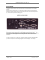
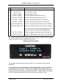
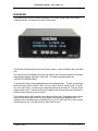
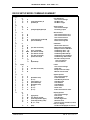

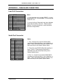
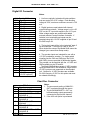
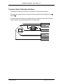

![Relazione elettrica [file]](http://vs1.manualzilla.com/store/data/006113298_1-fe18508ef55ebc347a9cb1e3b01b8f1e-150x150.png)