1
User’s
Manual
Model CX1000/CX1006/CX1200/CX1206
DAQSTATION CX1000
IM 04L31A01-03E
Yokogawa Electric Corporation
6th Edition
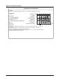
Thank you for purchasing the CX1000. This manual describes the functions (excluding
the communications functions), installation and wiring procedures, operating procedures,
and handling precautions of the CX1000. To ensure correct use, please read this
manual thoroughly before beginning operation. The following manuals are also provided
in addition to this manual. Read them along with this manual.
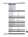
Electronic Manuals Provided on the Accompanying CD-ROM
Manual Title
Manual No.
Description
CX1000/CX2000
Communications Interface
User’s Manual
IM 04L31A01-17E
Describes the communications functions of the
CX1000/CX2000 using the Ethernet/serial interface.
Manual Title
Manual No.
Description
CX1000 Opration Guide
IM 04L31A01-04E
A guide providing simple explanations of
control-related operations for the CX1000
(includes a chart of setting values).
CX1000 Installation and
Connection Guide
IM 04L31A01-73E
Describes concisely the installation
procedures and wiring procedures of the CX1000.
Precautions on the Use of
the CX1000/CX2000
IM 04L31A01-72E
Precautions regarding the use of the CX1000/CX2000.
The same information is written on pages ii and iii of
this user’s manual.
Paper Manuals
CX1000/CX2000 Control of
IM 04L31A01-91C
Pollution Caused by the Product
Gives a description of pollution control.
DAQSTANDARD Manuals
All manuals other than IM 04L41B01-66EN are contained in the DAQSTANDARD CD.
Manual Title
Manual No.
DAQSTANDARD Data Viewer User’s Manual
IM 04L41B01-63EN
DAQSTANDARD Hardware Configurator User’s Manual
IM 04L41B01-64EN
Installing DAQSTANDARD
IM 04L41B01-66EN
Notes
• This manual describes the CX1000, style number “S3.”
• The contents of this manual are subject to change without prior notice as a result of
continuing improvements to the instrument’s performance and functions.
• Every effort has been made in the preparation of this manual to ensure the accuracy of
its contents. However, should you have any questions or find any errors, please contact
your nearest YOKOGAWA dealer.
• Copying or reproducing all or any part of the contents of this manual without the
permission of Yokogawa Electric Corporation is strictly prohibited.
• The TCP/IP software of this product and the document concerning the TCP/IP
software have been developed/created by YOKOGAWA based on the BSD
Networking Software, Release 1 that has been licensed from the Regents of the
University of California.
Trademarks
• vigilantplant, DAQSTATION, and Daqstation are registered trademarks of Yokogawa
Electric Corporation.
• Microsoft and Windows are registered trademarks or trademarks of Microsoft
Corporation in the United States and/or other countries.
• Adobe and Acrobat are registered trademarks or trademarks of Adobe Systems
Incorporated.
• Company and product names that appear in this manual are registered trademarks or
trademarks of their respective holders.
• The company and product names used in this manual are not accompanied by
registered trademark or trademark symbols (® and ™).
Revisions
1st Edition
2nd Edition
3rd Edition
March 2002
April 2002
June 2003
6th Edition : June 2010 (YK)
All Rights Reserved, Copyright © 2002 Yokogawa Electric Corporation
IM 04L31A01-03E
4th Edition
5th Edition
6th Edition
November 2003
May 2007
June 2010
i
Safety Precautions
About This Manual
• This manual should be read by the end user.
• Read this manual thoroughly and have a clear understanding of the product before operation.
• This manual explains the functions of the product. YOKOGAWA does not guarantee that the product will suit
a particular purpose of the user.
• Under absolutely no circumstances may the contents of this manual be transcribed or copied, in part or in
whole, without permission.
• The contents of this manual are subject to change without prior notice.
• Every effort has been made in the preparation of this manual to ensure the accuracy of its contents.
However, should you have any questions or find any errors or omissions, please contact your nearest
YOKOGAWA dealer.
Precautions Related to the Protection, Safety, and Alteration of the Product
• The following safety symbols are used on the product and in this manual.
“Handle with care.” (To avoid injury, death of personnel or damage to the instrument, the operator
must refer to the explanation in the manual.)
Functional ground terminal. (Do not use this terminal as a protective ground terminal.)
Protective grounding terminal
Alternating current
Direct current
• For the protection and safe use of the product and the system controlled by it, be sure to follow the
instructions and precautions on safety that are stated in this manual whenever you handle the product. Take
special note that if you handle the product in a manner that violate these instructions, the protection
functionality of the product may be damaged or impaired. In such cases, YOKOGAWA does not guarantee
the quality, performance, function, and safety of the product.
• When installing protection and/or safety circuits such as lightning protection devices and equipment for the
product and control system or designing or installing separate protection and/or safety circuits for fool-proof
design and fail-safe design of the processes and lines that use the product and the control system, the user
should implement these using additional devices and equipment.
• If you are replacing parts or consumable items of the product, make sure to use parts specified by
YOKOGAWA.
• This product is not designed or manufactured to be used in critical applications that directly affect or threaten
human lives. Such applications include nuclear power equipment, devices using radioactivity, railway
facilities, aviation equipment, air navigation facilities, aviation facilities, and medical equipment. If so used, it
is the user’s responsibility to include in the system additional equipment and devices that ensure personnel
safety.
• Do not modify this product.
• The CX is designed for indoor use.
ii
IM 04L31A01-03E
Safety Precautions
WARNING
Power Supply
Ensure that the source voltage matches the voltage of the power supply before turning ON the power.
Protective Grounding
Make sure to connect the protective grounding to prevent electric shock before turning ON the power.
Necessity of Protective Grounding
Never cut off the internal or external protective earth wire or disconnect the wiring of the protective
earth terminal. Doing so invalidates the protective functions of the instrument and poses a potential
shock hazard.
Defect of Protective Grounding
Do not operate the instrument if the protective earth or fuse might be defective. Make sure to check
them before operation.
Do Not Operate in an Explosive Atmosphere
Do not operate the instrument in the presence of flammable liquids or vapors. Operation in such
environments constitutes a safety hazard.
Do Not Remove Covers
The cover should be removed by YOKOGAWA’s qualified personnel only. Opening the cover is
dangerous, because some areas inside the instrument have high voltages.
External Connection
Connect the protective grounding before connecting to the item under measurement or to an external
control unit.
Damage to the Protective Structure
Operating the CX1000 in a manner not described in this manual may damage its protective structure.
Exemption from Responsibility
• YOKOGAWA makes no warranties regarding the product except those stated in the WARRANTY that is
provided separately.
• YOKOGAWA assumes no liability to any party for any loss or damage, direct or indirect, caused by the user
or any unpredictable defect of the product.
Handling Precautions of the Software
• YOKOGAWA makes no warranties regarding the software accompanying this product except those stated in
the WARRANTY that is provided separately.
• Use the software on a single PC.
• You must purchase another copy of the software, if you are to use the software on another PC.
• Copying the software for any purposes other than backup is strictly prohibited.
• Please store the original media containing the software in a safe place.
• Reverse engineering, such as decompiling of the software, is strictly prohibited.
• No portion of the software supplied by YOKOGAWA may be transferred, exchanged, sublet, or leased for
use by any third party without prior permission by YOKOGAWA.
IM 04L31A01-03E
iii
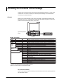
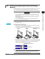
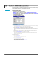
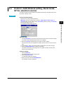
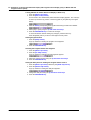
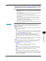
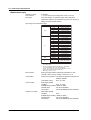
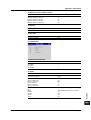
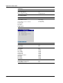
Checking the Contents of the Package
Unpack the box and check the contents before operating the instrument. If some of the
contents are not correct or missing or if there is physical damage, contact the dealer
from which you purchased them.
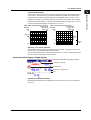
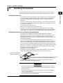
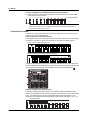
CX1000
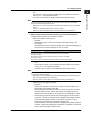
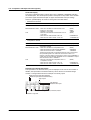
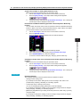
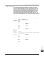
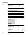
When you open the operation cover on the front panel, a name plate is located on the
back side of the cover. Check that the model name and suffix code given on the name
plate on the rear panel match those on the order.
Open the operation
cover
STYLE
MODEL
SUFFIX
STYLE
NO
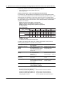
MODEL and SUFFIX
Model
CX1000
CX1006
CX1200
CX1206
External
storage
medium
Suffix Code
–1
–2
–3
–5
Communication
interface
Displayed language
Options
Optional Code
–0
–1
–2
–1
–2
/A6
/A6R
/A4F
/A4FR
/M1
/N2
/P1
/PG1
/PG2
/BT1
*1
*2
Description
Number of internal control loops: 0, number of inputs for measurement: 0 ch
Number of internal control loops: 0, number of inputs for measurement: 6 ch
Number of internal control loops: 2, number of inputs for measurement: 0 ch
Number of internal control loops: 2, number of inputs for measurement: 6 ch
Floppy disk
100MB Zip disk
ATA flash memory card (Compact flash and adapter)
250MB Zip disk
Ethernet
Ethernet + RS-232 serial interface port
Ethernet + RS-422A/485 serial interface port
Japanese
English
6 measurement alarm outputs*1
6 measurement alarm output, 8 remote inputs*1
4 measurement alarm outputs, 1 FAIL output, 1 memory end output*1
4 measurement alarm outputs, 1 FAIL output, 1 memory end output,
8 remote inputs*1
Computation function
Three-wire isolated RTD (input for measurement)
24-VDC/AC power supply driven
Program control (number of program patterns: 4)*2
Program control (number of program patterns: 30)*2
Batch header
Only one can be specified at once on the CX1000 and CX1006.
Either one can be specified on the CX1200 and CX1206.
NO. (Instrument Number)
When contacting the dealer from which you purchased the instrument, please give them
the instrument number.
iv
IM 04L31A01-03E
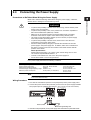
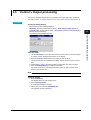
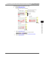
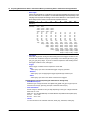
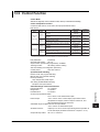
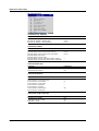
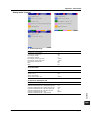
Checking the Contents of the Package
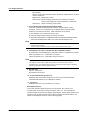
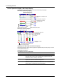
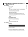
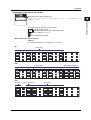
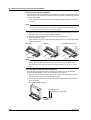
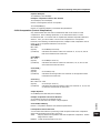
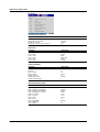
Standard Accessories
The standard accessories below are supplied with the instrument. Check that all
contents are present and that they are undamaged.
or
1
2
3
5
4
No. Name
7
6
8
Part Number/Model Q’ty Note
1
Terminal screws
5
M4
2
Mounting bracket
B9900BX
2
For panel mounting
3
DAQSTANDARD
DXA120
1
Software for setting the CX and
displaying data. CD-ROM used to install
“DAQSTANDARD”
4
CX1000/CX2000
electronic manual
B8700MA
1
CD-ROM containing the PDF files of this
manual, the CX1000/CX2000
Communication Interface User’s Manual,
DAQSTANDARD for CX User’s Manual,
and other files.
5
CX1000 Operation
Guide
IM 04L31A01-04E
1
A guide providing simple explanations of
control-related operations for the CX1000
(includes a chart of setting values).
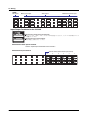
6
CX1000 Installation and IM 04L31A01-73E
Connection Guide
1
Abridged paper manual
7
Precautions on the Use IM 04L31A01-72E
1
of the CX1000/CX2000
CX1000/CX2000
IM 04L31A01-91C 1
Control of Pollution
Caused by the Product
Installing DAQSTANDARD IM 04L41B01-66EN 1
Paper stating the precautions.
External storage medium A1053MP
1
A1056MP
1
B9968NL
1
100 MB Zip disk (provided only when the
external storage medium suffix code is “-2”)
250 MB Zip disk (provided only when the
external storage medium suffix code is “-5”)
ATA flash memory card(32 MB CF card +
adapter,capacity model of CF card may
vary) provided only when the external
storage medium suffix code is “-3”
8
Gives a description of pollution control.
Describes the installation procedures.
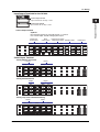
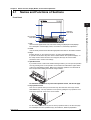
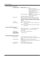
Optional Accessories (Sold Separately)
The following optional accessories are available for purchase separately. When you
receive the order, check that all contents are present and that they are undamaged.
For information and ordering, contact your nearest YOKOGAWA dealer.
Part Name
Part Number/Model
Q’ty
Note
3.5" floppy disk
7059 00
10
2HD
Zip disk
A1053MP
A1056MP
1
1
100 MB
250 MB
ATA flash memory card
B9968NL
1
32 MB (32 MB CF card + adapter,
capacity and model of CF card may
vary)
Shunt resistance
(for the screw terminal)
4159 20
4159 21
1
1
250 Ω±0.1%
100 Ω±0.1%
4159 22
1
10 Ω±0.1%
B9900BX
2
Mounting bracket
IM 04L31A01-03E
v
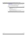
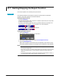
How to Use This Manual
Structure of the Manual
This user’s manual consists of the following sections. For details on the communications
functions and the software “DAQSTANDARD” provided with the package, see the
respective manuals (IM 04L31A01-17E, IM 04L41B01-63EN, and IM 04L41B01-64EN).
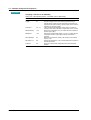
Chapter
Title and Description
1
Explanation of Functions
Describes in detail the functions of the instrument. The chapters that explain the
operation of the CX1000 only describe the operating procedures. For more detailed
information about the functions, see this chapter.
2
Installation and Wiring
Describes the installation and wiring procedures of the CX1000.
3
Names of Parts, Display Modes, and Common Operations
Describes the names of the parts of the CX1000, the basic key operations, the basic
operations carried out initially, and how to use the external storage medium drive.
4
Control Function Related Setup Operations
Describes setup operations related to the control function that are carried out before
starting control operations.
5
Program Control Related Setup Operations (Only on Models with the Program
Control Option)
Describes the setup operations related to program control that are carried out before
starting control operations on models with the program control option.
6
Operations during Control Operation
Describes how to switch operation mode during control operation, how to change the
setpoints of setting mode, how to tune the control parameters, and the operations on
the program control screen (operations only on models with the option).
7
Measurement Function Related Setup Operations
Describes how to set the PV input of the measurement function and alarms
(measurement alarms).
8
Operations for Changing the Displayed Contents
Describes how to change the operating display of both the control function and the
measurement function and the display format.
9
Data Save/Load Operations
Describes how to write various data to the internal memory, how to save and load from
the external storage medium, and the file operations on the external storage medium.
10
Computation and Report Function Related Operations (Only on Models with the
Computation Function Option)
Describes how to set and execute operations related to the computation function and
report function of the computation function option.
11
Operations of Other Functions
Describes the USER key, key lock, login/logout of key operation, log display, and
remote input setting.
12
Troubleshooting
Describes the error messages and the troubleshooting measures of the CX1000.
13
Maintenance
Describes periodic inspection, calibration, and recommended replacement period for
worn parts.
14
Specifications
Describes the specifications of the CX1000.
Appendix
Describes the acquisition function of measured data to the internal memory, additional
information on the computation and report functions, the ASCII file format, and initial settings.
Index
Note
•
•
vi
This user’s manual covers information regarding CX1000s that have a suffix code for
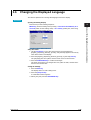
language “-2” (English).
For details on setting the displayed language, see section 3.6.
IM 04L31A01-03E
How to Use This Manual
Conventions Used in This Manual
Unit
K........ Denotes “1024.” Example: 768 KB (file size)
k........ Denotes “1000.”
Safety Markings
The following markings are used in this manual.
Danger. Refer to corresponding location on the instrument.
This symbol appears on dangerous locations on the instrument
which require special instructions for proper handling or use. The
same symbol appears in the corresponding place in the manual to
identify those instructions.
WARNING
Calls attention to actions or conditions that could cause serious
injury or death to the user, and precautions that can be taken to
prevent such occurences.
CAUTION
Calls attentions to actions or conditions that could cause damage to
the instrument or user’s data, and precautions that can be taken to
prevent such occurrences.
Note
Calls attention to information that is important for proper operation
of th instrument.
Symbols Used on Pages Describing Operating Procedures
On pages that describe the operating procedures in Chapter 3 through 11, the following
symbols are used to distinguish the procedures from their explanations.
[ ] ................
Indicates character strings that appear on the screen.
Example: [Space] soft key, [Volt]
Procedure
This subsection contains the operating procedure used to carry out
the function described in the current section. All procedures are
written with inexperienced users in mind; experienced users may
not need to carry out all the steps.
Setup Items
Describes the details of the settings and the restrictions that exist with
the operating procedure. It does not give a detailed explanation of
the function. For details on the function, see chapter 1.
the function. For details on the function, see chapter 1.
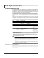
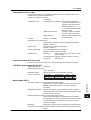
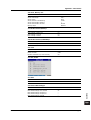
Revision History
IM 04L31A01-03E
Edition
Addition and Change to Functions
5
Added the contents of IM04L31A01-05E (the user’s manual describing changes to
functions with version 3.02 or later) to the user’s manual, and discarded IM04L31A0105E. Added an I/O terminal diagram. Added example expressions.
6
The DAQSTANDARD is revised.
vii
Contents
Safety Precautions .......................................................................................................................... ii
Checking the Contents of the Package .......................................................................................... iv
How to Use This Manual ................................................................................................................ vi
Chapter 1 Explanation of Functions
1.1
1.2
1.3
1.4
1.5
1.6
1.7
1.8
1.9
1.10
1.11
1.12
1.13
1.14
1.15
1.16
1.17
1.18
1.19
1.20
CX1000 Overview ............................................................................................................ 1-1
Control Function Overview ............................................................................................... 1-2
Basic Settings of Control ................................................................................................ 1-16
PV Input Related Settings .............................................................................................. 1-21
Contact Input/Output Related Settings .......................................................................... 1-25
Target Setpoint Related Settings ................................................................................... 1-29
PID Parameter Settings ................................................................................................. 1-31
Control Output Suppression Settings ............................................................................. 1-35
Settings for ON/OFF Control .......................................................................................... 1-37
Control Alarm Related Settings ...................................................................................... 1-38
Program Control Related Settings ................................................................................. 1-40
Tuning ............................................................................................................................ 1-54
Measurement Function Overview .................................................................................. 1-56
Measurement Function > Measurement Input Related Settings .................................... 1-58
Measurement Function > Measurement Alarm Related Settings ................................... 1-61
Display Function ............................................................................................................ 1-66
Data Storage Function ................................................................................................... 1-86
Computation and Report Functions (Option) ................................................................. 1-91
Equations for Control Computation (Style Number S3 or Later) .................................... 1-95
Other Functions ............................................................................................................. 1-96
Chapter 2 Installation and Wiring
2.1
2.2
2.3
2.4
Handling Precautions ....................................................................................................... 2-1
Installation ........................................................................................................................ 2-2
Wiring ............................................................................................................................... 2-5
Connecting the Power Supply ........................................................................................ 2-17
Chapter 3 Names of Parts, Display Modes, and Common Operations
3.1
3.2
3.3
3.4
3.5
3.6
3.7
3.8
Names and Functions of Sections ................................................................................... 3-1
Basic Key Operations ...................................................................................................... 3-4
Setting the Date and Time ............................................................................................. 3-11
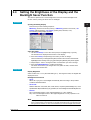
Setting the Brightness of the Display and the Backlight Saver Function ....................... 3-13
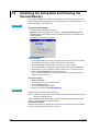
Initializing the Setup Data and Clearing the Internal Memory ........................................ 3-14
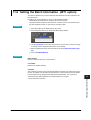
Changing the Displayed Language ................................................................................ 3-15
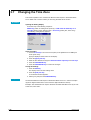
Changing the Time Zone ................................................................................................ 3-16
Inserting and Ejecting the External Storage Medium ..................................................... 3-17
Chapter 4 Control Function Related Setup Operations
4.1
4.2
4.3
4.4
4.5
4.6
viii
Control > Control action ................................................................................................... 4-1
Control > Input setting (Burnout and RJC) ....................................................................... 4-4
Control > DI/DO/SW-registration ...................................................................................... 4-6
Control > AUX (Remote setting, Alarm mode, SP No. selection source) ....................... 4-11
Control > Output processing .......................................................................................... 4-13
Control > Relay .............................................................................................................. 4-15
IM 04L31A01-03E
Contents
4.7
4.8
4.9
4.10
4.11
4.12
4.13
4.14
4.15
4.16
4.17
4.18
4.19
4.20
4.21
Control > Tuning setting ................................................................................................. 4-17
Control input range ........................................................................................................ 4-19
Control alarm ................................................................................................................. 4-23
Operation-related parameters/Zone PID ........................................................................ 4-25
PID parameters .............................................................................................................. 4-27
Control group setting ...................................................................................................... 4-29
Ten-segment linearizer I/O ............................................................................................. 4-31
Control Function Settings ............................................................................................... 4-33
Hysteresis (Alarm) ......................................................................................................... 4-35
DIO Operation Monitoring Function Settings (Style Number S3 or Later) ..................... 4-37
DI/DO Label Settings (Style Number S3 or Later) ......................................................... 4-40
PV/SP Computation and Analog Retransmission Settings (Style Number S3 or Later) 4-41
Logic Computation Settings (Style Number S3 or Later) ............................................... 4-45
Control Constant Settings (Style Number S3 or Later) .................................................. 4-47
Settings for Switching the Program Patterns Using Contact Inputs with BCD Codes
(Version 3.20 or Later) ................................................................................................... 4-49
Chapter 5 Program Control Related Setup Operations
5.1
5.2
5.3
5.4
5.5
5.6
5.7
5.8
5.9
5.10
5.11
Program Pattern Setup Procedure ................................................................................... 5-1
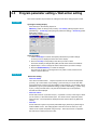
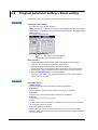
Program parameter setting > Pattern initial setting .......................................................... 5-2
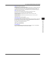
Program parameter setting > Wait action setting ............................................................. 5-4
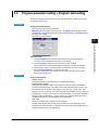
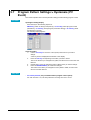
Program parameter setting > Program start setting ......................................................... 5-5
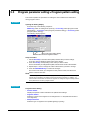
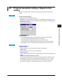
Program parameter setting > Program pattern setting ..................................................... 5-6
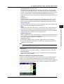
Program parameter setting > Event setting ..................................................................... 5-8
Program Pattern Settings > Hysteresis (PV Event) ....................................................... 5-10
Program parameter setting > Repeat action setting ...................................................... 5-11
Event Output Settings .................................................................................................... 5-12
AUX (Auto message, Display position) .......................................................................... 5-14
AUX (Event Group) Settings (Style Number S3 or Later) .............................................. 5-16
1
2
3
4
5
6
7
8
9
Chapter 6 Operations during Control Operation
6.1
6.2
6.3
6.4
Operations on the Control Group Display (Switching Displayed Information and Control
Operation Modes) ............................................................................................................ 6-1
Switching Displays on the Overview Display ................................................................... 6-7
Tuning Operation ............................................................................................................. 6-8
Operations on the Program Selection Display and Program Control Display (Only on
Models with the Program Control Option) ...................................................................... 6-12
Chapter 7 Measurement Function Related Setup Operations
7.1
7.2
7.3
Settings Related to Measurement Inputs ......................................................................... 7-1
Settings Related to Measurement Alarms ........................................................................ 7-6
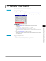
Setting the Temperature Unit ......................................................................................... 7-11
8.2
8.3
8.4
8.5
8.6
8.7
IM 04L31A01-03E
11
12
13
Chapter 8 Operations for Changing the Displayed Contents
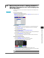
8.1
10
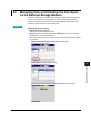
Using the Information Display (Alarm Summary, Message Summary, Memory Summary,
and Control Summary) ..................................................................................................... 8-1
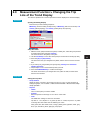
Measurement Function > Measurement Group Setup Operation .................................... 8-2
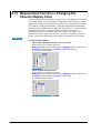
Measurement Function > Settings Related to Tag Display for Channels ......................... 8-4
Measurement Function > Operations When Displaying Trend, Digital, and Bar Graph
Displays ........................................................................................................................... 8-6
Measurement Function > Operations When Displaying the Overview ............................ 8-8
Measurement Function > Operations When Displaying the Historical Trend .................. 8-9
Measurement Function > Changing the Display Update Rate of the Trend Display ...... 8-10
ix
14
App
Index
Contents
8.8
8.9
8.10
8.11
8.12
8.13
8.14
Measurement Function > Settings Related to Messages Displayed on the Trend Display
and Write Operation ....................................................................................................... 8-11
Measurement Function > Changing the Trip Line of the Trend Display ......................... 8-13
Measurement Function > Changing the Channel Display Color .................................... 8-14
Measurement Function > Changing the Zone Display of the Trend Display .................. 8-16
Measurement Function > Setting the Scale Division, Bar Graph Base Position, Scale
Position of Trend Displays ............................................................................................. 8-17
Measurement Function > Setting the Partial Expanded Display on the Trend Display .. 8-21
Measurement Function > Setting the Display Direction, Background Color, Waveform Line
Width, Trip Line Width, Grid, and Scroll Time ................................................................ 8-23
Chapter 9 Data Save/Load Operations
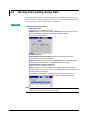
9.1
9.2
9.3
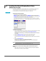
9.4
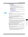
9.5
9.6
9.7
Acquiring Measurement Data to the Internal Memory and Saving Data to the External
Storage Medium ............................................................................................................... 9-1
Saving Measured/Computed Data at Arbitrary Times (Manual Sample) ......................... 9-7
Saving and Loading Setup Data ...................................................................................... 9-8
Loading the Stored Display/Event Data (Historical Trend) ............................................. 9-10
Managing Files and Checking the Free Space on the External Storage Medium ......... 9-11
Saving the Screen Image Data ...................................................................................... 9-14
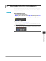
Clearing the Data in the Internal Memory ...................................................................... 9-15
Chapter 10 Computation and Report Function Related Operations (Only on
Models with the Computation Function Option)
10.1
10.2
10.3
10.4
10.5
10.6
10.7
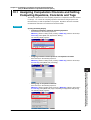
Assigning Computation Channels and Setting Computing Equations,
Constants and Tags ....................................................................................................... 10-1
Starting, Stopping, and Resetting the Computation ....................................................... 10-4
Setting Computation Channel Alarms ............................................................................ 10-5
Setting TLOG Computations .......................................................................................... 10-8
Setting the Rolling Average .......................................................................................... 10-11
Creating Reports .......................................................................................................... 10-12
Starting/Stopping the Report Function ......................................................................... 10-14
Chapter 11 Operations of Other Functions
11.1
11.2
11.3
11.4
11.5
11.6
11.7
11.8
USER Key Assignment and Operation .......................................................................... 11-1
Key Lock ........................................................................................................................ 11-3
Key Operation Login/Logout .......................................................................................... 11-5
Displaying Logs (Checking Operations) and System Information Display (Checking the
System Specifications) ................................................................................................... 11-8
Setting the Measurement Remote Input (/A6R option or /A4FR option) ...................... 11-11
Setting Whether or Not to Use the Batch Header (/BT1 option) ................................. 11-14
Setting the Batch Information (/BT1 option) ................................................................ 11-15
Setting the Batch Information (/BT1 option) ................................................................ 11-17
Chapter 12 Troubleshooting
12.1
12.2
Messages ....................................................................................................................... 12-1
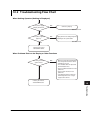
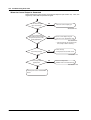
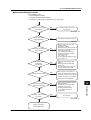
Troubleshooting Flow Chart ......................................................................................... 12-11
Chapter 13 Maintenance
13.1
13.2
13.3
x
Periodic Inspection ......................................................................................................... 13-1
Calibration ...................................................................................................................... 13-2
Replacement of Parts .................................................................................................... 13-4
IM 04L31A01-03E
Contents
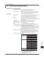
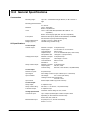
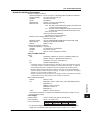
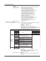
Chapter 14 Specifications
14.1
14.2
14.3
14.4
14.5
14.6
14.7
14.8
14.9
1
Input Section Specifications ........................................................................................... 14-1
Control Function ............................................................................................................. 14-3
Alarm Function ............................................................................................................... 14-5
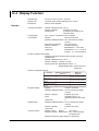
Display Function ............................................................................................................ 14-6
Storage Function ............................................................................................................ 14-8
Communication Functions ........................................................................................... 14-11
Options ......................................................................................................................... 14-13
General Specifications ................................................................................................. 14-16
Dimensional Drawings ................................................................................................. 14-20
2
3
4
Appendix
Appendix 1
Supplementary Explanation of the Acquisition of Display Data/Event Data to the
Internal Memory ........................................................................................................... App-1
Appendix 2
Supplementary Explanation of the Computation Function .............................. App-6
Appendix 3
Meaning and Syntax of Equations ................................................................. App-11
Appendix 4
Additional Explanation of the Report Function .............................................. App-17
Appendix 5
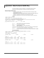
Data Format of ASCII Files ............................................................................ App-20
Appendix 6
Initial Values .................................................................................................. App-24
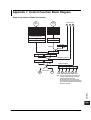
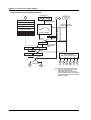
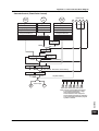
Appendix 7
Control Function Block Diagram .................................................................... App-39
Appendix 8
Explanation of Engineering Units (EU and EUS) ........................................... App-45
Appendix 9
Program Control Worksheets ........................................................................ App-46
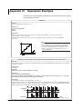
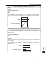
Appendix 10 Expression Examples .................................................................................... App-50
Index
5
6
7
8
9
10
11
12
13
14
App
IM 04L31A01-03E
xi
Index
Chapter 1 Explanation of Functions
1.1
1
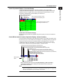
CX1000 Overview
• Control contact input
Relay output: 2 outputs
Transistor output: 4 outputs
LAN
(Ethernet)
Ethernet
Magnet
switch
SSR
Contact Contact
input
output
6 inputs 6 outputs
5 universal measurement inputs
3
4
5
6
7
9
CX1000
Serial interface
port
RS-422/485/232
Power
Supply
Control output terminal
block (Loops 1 and 2)
R1
2
8
PC
• Universal control output: for 2 loops
Select current, voltage pulse, or
relay output.
• Control contact input: 6 inputs
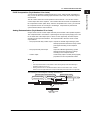
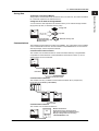
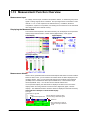
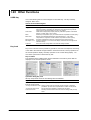
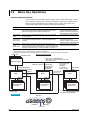
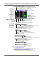
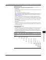
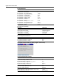
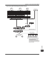
Explanation of Functions
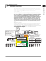
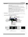
The CX1000 consists of a control function and a measurement function. The control
function executes control through PID control and ON/OFF control. The measurement
function displays and acquires measured data and control-output data.
Control Function
The CX1000 supports thee control modes: single-loop control, cascade control, loop
control with PV switching, and analog retransmission. It can handle up to two loops of
PID control. In addition, the UT Series controllers made by Yokogawa M&C Corporation
can be connected and controlled simultaneously as external loops (four loops max.).
You can check the control status on the controller style and faceplate style displays and
the hybrid style display that is a mixture of the two styles. Furthermore, the overview
display allows monitoring of all control loops including external loops. In addition, the
CX1000 provides auto-tuning of PID constants as well as manual tuning, which enables
you to adjust the control parameters such as PID constants while checking the control
status.
Measurement Function
In addition to the measured data for the control function, the CX1000 can acquire up to
six channels of measured data. The data can be displayed as waveforms, numeric
values, and bar graphs. The measured data along with the control data can be stored to
a floppy disk, Zip disk, or ATA flash memory card using the built-in drive.
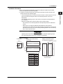
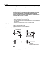
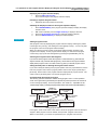
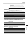
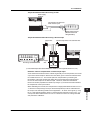
Conceptual Input/Output Diagram
Option terminal block
(Can be installed in place of
the control output terminal block)
Control loop
section
(select 0 or 2 loops)
Measurement input
section
Control/measurement input
terminal block
Control input
terminals
Controllers (up to
4 loops)
PLC
(such as the FA-M3
100 VAC to 240 VAC
by YOKOGAWA)
24 VDC/AC (/P1 option)
Select one from the following option
terminal blocks.
(/A6 option)
Measurement alarm
output + remote input/
output (/A6R option)
Measurement alarm output +
FAIL/memory end output
Measurement alarm
output + FAIL/memory
end output + remote
input/output (/A4FR option)
Measurement alarm output
(/A4F option)
6 universal measurement inputs
Measurement input
terminals
CH1 to CH6
10
11
12
13
14
IM 04L31A01-03E
1-1
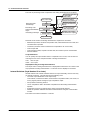
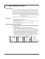
1.2
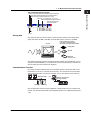
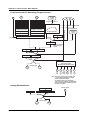
Control Function Overview
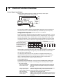
Control Signal Input/Output
As shown in the following figure, the CX1000 can control up to two loops.
···
Control PV input (number of analog inputs: 5)
• TC
[Up to 2 loops]
• RTD
etc.
Control output
• Relay
• Voltage pulse
• Current
Controls
···
CX
Object of
control
and
switches
DISP/
ENTER
• SSR
• Magnet switch
etc.
The UT Series controllers made by Yokogawa M&C Corporation can be connected via
the serial interface and controlled simultaneously as external loops (four loops max.)
(see the CX1000/CX2000 Communication Interface User’s Manual).
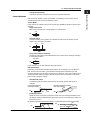
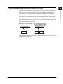
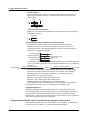
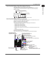
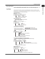
Analog Input for Loop Control
PV input and remote setpoint input (RSP) are available as control signal inputs. You can
select thermocouple, resistance temperature detector, standard signal, or DC voltage for
both PV input and RSP input. The RSP input is used as a terget setpoint (SP). There
are five input terminals on the control/measurement input terminal block. When PV/SP
computation is OFF, each input terminal is assigned depending on the number of loops
used and the control mode (see next page) as shown in the figure below.
[Control mode setting]
During single-loop control
During cascade control
During loop control with
PV switching
LOOP2
2
1
(RSP)
PV
3
PV
PV2
PV1
(RSP)
Measurement input terminals
LOOP1
2
(RSP)
1
PV
(RSP)
PV
PV2
PV1
PV, PV1, PV2: PV input, (RSP): RSP input
(not used during program control), : unused terminal
When PV/SP is ON, the numbers CI01, CI02, CI03, CI04, and CI05 are assigned to each
control input terminal starting on the right as you face the terminals, and the PV/SP of
each loop is the computed value.
You can apply scale conversion, bias, input filter, ten-segment linearizer bias, tensegment linearizer approximation, and square-root computation on the control signal
input. For thermocouple inputs, you can set reference junction compensation. In
addition, ratio setting can be specified against RSP inputs.
Control Signal Output
The terminal provides universal output. Two loops can be controlled (except cascade control
which uses two loops for one control). The following types of control output can be selected.
• PID control output
• Time proportional PID Outputs ON/OFF signals with a pulse width that is proportional
relay contact output:
to the time as relay contact signals according to the computed
PID value.
• Time proportional PID Outputs ON/OFF signals with a pulse width that is proportional to
voltage pulse output:
the time as voltages according to the computed PID value.
• Current output (continuous Continuously outputs a current (analog signal) that is
PID control output):
proportional to the computed PID value.
• On/off control relay
Outputs on/off control relay contact signals according to the
contact output:
polarity (positive/negative) of the deviation between the SP
and the PV.
1-2
IM 04L31A01-03E
1.2 Control Function Overview
1
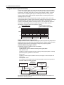
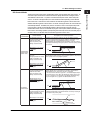
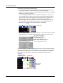
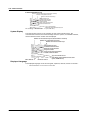
Control Methods
PID control and ON/OFF control are available. The following control modes can be
selected for both PID control and ON/OFF control.
Control Mode
In PID control, the following three control modes are available in relation to the PV input
selection.
• Single-loop control
Basic control consisting of a single system of controller CPU.
PV
SP
2
3
4
PID
OUT
5
• Cascade control
Control consisting of two systems of controller CPUs that use the primary control
output as the secondary control SP.
PV2
PV1
SP
Explanation of Functions
• Analog Retransmission
Outputs the specified computed result, not the computed PID value.
6
PID
PID
7
OUT
• Loop control with PV switching
Single-loop control that is switched between two PV inputs (PV1 and PV2) according
to a specified condition.
8
PV1 PV2
SP
PID
9
OUT
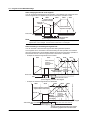
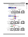
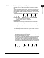
In PID control, you can also select the PID control mode.
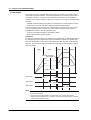
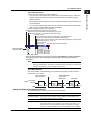
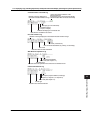
PID Control Mode
Depending on the desired operation at the time the SP is changed, you can select the
PID control mode from below. The selections between the PV derivative type and
deviation derivative type as well as the presence or absence of the control output bumps
are automatically made according to the PID control mode and operation mode (fixedpoint control or program control).
• Standard PID control
Controlled so that the control output reaches the new SP quickly after the SP is
changed.
SP
PV
SP
OUT
13
OUT
• Fixed-point control
Select this mode if you wish to avoid the control OUT from reacting sensitively to the
SP change causing a disturbance in the control such as in the case with a continuous
fixed-point control.
PV derivative type PID (without output bump) PV derivative type PID (with output bump)
PV
SP
SP
PV
IM 04L31A01-03E
OUT
11
12
Deviation derivative type PID
(with output bump)
PV
PV derivative type PID
(with output bump)
10
OUT
1-3
14
1.2 Control Function Overview
Control Parameters
The following control parameters are available. For each group, you can enter up to
eight sets of SPs and PID parameters as underlined below.
SP, PID constant, control output limiter, ON/OFF of the shutdown function, manual reset
value, relay hysteresis, control action direction, preset output, SP tracking, PV tracking,
setpoint limiter, output velocity limiter, auto/manual switching of the over-integration
prevention function (anti-reset windup), ON/OFF of the control output suppression
function, and SP ramp-rate.
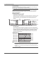
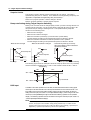
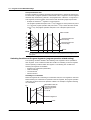
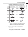
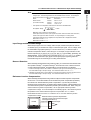
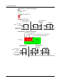
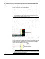
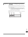
PID Selection Method
The following two methods are available.
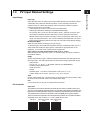
• Target setpoint selection method
A group (up to 8 groups) consisting of a SP and PID parameters is registered to a PID
number (SP number). By specifying the SP number using keys on the front panel,
external contact input, or via communications, the SP and PID parameters are
switched.
PV Rise according to the
setpoint ramp-up
setting
SP3
(No.3PID)
Fall according to the
setpoint ramp-down SPn: Target setpoint number
setting
SP2
(No.2PID)
SP1
SP1
(No.1PID)
(No.1PID)
Switch from SP1 to SP3
Switch from SP3 to SP1
Rise according to the
setpoint ramp-up
setting
Time
Switch from SP1 to SP2
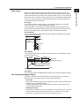
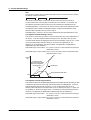
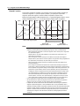
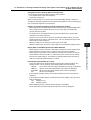
• Zone PID method
The measurement span is divided into a maximum of seven zones using reference
points. The optimum PID constant is preassigned to each zone, and the PID constant
(in actuality, other control parameters that are registered using the PID number are
included) is automatically switched according to the PV. This method is suited for
controlling equipment such as reactors in which the chemical reaction gain varies
depending on the temperature.
Maximum value of
measurement span
If the current PV is here, PID
Reference point 6
constant of PID No. 5 is used
for control.
Reference point 5
No.7 PID
No.6 PID
No.5 PID
Reference point 4
No.4 PID
Reference point 3
Reference point 2
No.3 PID
No.2 PID
Reference point 1
Minimum value of
measurement span
Change in the
PV.
No.1 PID
Note
•
•
1-4
When performing program control operation on models with the program control option,
you will select between segment PID method (zone PID selection OFF) and zone PID
method.
For a description on auto tuning, which automatically sets the optimum PID constant, see
section 1.12, “Tuning.”
IM 04L31A01-03E
1.2 Control Function Overview
1
Alarm Output
Explanation of Functions
When the control action status matches the preset status (up to 4 points per loop), the
CX1000 can output a relay contact signal from the control output terminal block or the DIO
expansion terminal block, and output it to the internal switches. Also, you can display the
alarm status on the CX screen. In relay contact output, you can select and assign the type
of alarm you wish to output at each output terminal of the control output terminal block or
the control DIO extension terminal block.
Alarm Type
You can select the alarm type from below. For a detailed explanation on each alarm
output, see section 1.10, “Control Alarm Related Settings.”
PV high-limit alarm, PV low-limit alarm, deviation high-limit alarm, deviation low-limit
alarm, deviation high & low limit alarm, deviation within high & low limits alarm, SP highlimit alarm, SP low-limit alarm, output high-limit alarm, and output low-limit alarm.
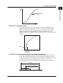
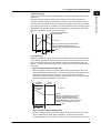
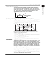
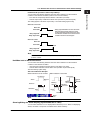
Alarm Hysteresis
You can set a hysteresis to the setpoints used in the activation and releasing of the alarm.
2
3
4
5
Example of PV high limit alarm
ON
OFF
6
Alarm setpoint
Hysteresis
PV
Alarm ON
7
OFF
ON
OFF
Time
8
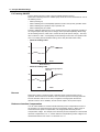
Alarm Standby
You can put the alarm output on standby at the initial stage of control operation until the
PV input reaches the SP.
PV
Normal
handling
Normal
Failure
Alarm output ON
9
Hysteresis
Alarm low limit value
10
Alarm is not output during this
period even if the PV is below
the alarm low limit.
Time
11
Power up
Alarm Mode
You can set the condition for disabling the alarm output (such as when the operation is stopped).
12
FAIL Output/Self Diagnosis Output
In addition to the alarm output described above, the following relay contact signal for
failure detection can be output from the control output terminal block.
• FAIL output
Output when a failure is detected in the CX1000 CPU. When a failure is detected, the
CX1000 is put in the following condition.
Control: Stopped (preset output if in the middle of operation, control output is off or
0% when power is turned ON)
• Self diagnosis output
Output when an input burnout, A/D converter failure, or RJC failure occurs. If an input
burnout or A/D converter failure is detected, the control output is set to the preset
output value. For RJC, PID control continues as though RJC is 0 °C.
IM 04L31A01-03E
1-5
13
14
1.2 Control Function Overview
Control Operation Mode
The following control operation switching is available. The control operation can be
switched using keys on the CX1000 control group display (see page 1-14), using contact
inputs, or via communications. For a description of the control operation modes on
models with the program control option, see “Program Control” in the next section. The
control function block diagram in the explanation below is a simplified one. For a
detailed control function block diagram for each control mode, see appendix 7.
Switching between Remote (REM) and Local (LOC)
Select whether control is executed using the SPs set on the CX1000 or using the
external analog signal (RSP) as the SP.
PV input
PV
RSP input
RSP
(Analog signal)
SP
Local
(LOC)
Remote
(REM)
Controller CPU
Control output
OUT
Switching between Auto (AUT), Manual (MAN), and Cascade (CAS)
When set to auto, the control output value (OUT) is computed from the deviation between the PV
input and the SP. When set to manual, the control output value (OUT) that is set manually is
used rather than the computed control output value (OUT). Switching to “cascade (CAS)” is
possible only when the control mode is set to “cascade control.” In cascade control, the primary
PID control output is used as the SP of the secondary PID control.
Switching between Run (RUN) and Stop (STP)
When the operation is stopped, the control output value (OUT) is set to the preset value.
Single-loop control
PV input
PV
Cascade control
SP
Manual operation Controller CPU
Auto (AUT)
Manual (MAN)
PV input 2
(Cascade secondary)
PV input 1
(Cascade primary)
PV1
PV2
SP1
Controller CPU 1
Cascade
Preset output
Stop (STP)
Output limiter
Run (RUN)
SP2
Auto/
Manual
Manual operation Controller CPU 2
Cascade/
Auto
(CAS/AUT)
Manual (MAN)
Control output
OUT
Preset output
Stop (STP)
Output limiter
Run (RUN)
Control output
OUT
Enabling/Disabling Auto-Tuning
In PID control, the optimum PID constant is set automatically when auto-tuning (see
page 1-54) is performed. Auto-tuning is possible only during auto operation.
Contact Input
Contact input can be used to carry out operations such as running/stopping operation,
switching operation modes, changing SPs, switching PV inputs (during loop control with
PV switching). For a description on the possible operations, see “Contact Input
Information Registration” on page 1-26.
1-6
IM 04L31A01-03E
1.2 Control Function Overview
1
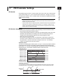
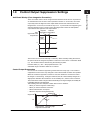
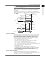
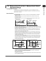
PV/SP Computation (Style Number S3 or Later)
Analog Retransmission (Style Number S3 or Later)
Output comes from the control output channels per the results of the specified equation.
The computed result is converted to a percentage of the output span (ranging from 0.0%
for the lower limit of the output span to 100.0% for the upper limit), and then outputs
according to the output format below. The output interval is the same as the control
output interval.
• Time proportional relay contact output: Outputs an ON/OFF signal having a pulse
width proportional to the time as relay contact
point signal according to the computed
values.
• Time proportional pulse output:
Output an ON/OFF signal having a pulse
width proportional to the time as voltage
according to the computed values.
• Current output:
Continuously output a current (analog signal)
proportional to the computed PID values.
Explanation of Functions
You can use the specified computed result as PV or SP. When PV/SP computation is
ON, you can set the control analog input terminals to CI01–CI05, and set the range for
each channel.
The SP is active when the control operation mode is Remote. You can also use the
control output value in the equation. The constants that can be used are separate from
the computation function (W01–W12). When a computation error occurs, you can treat
the computed result as an overrange or underrange. Computation is performed in
synchronization with the control interval.
2
3
4
5
6
7
8
Note
•
•
•
The output value while initialization occurs after turning the power ON or OFF is 0 mA or 0
V.
The output value while in setup mode or when closing setup mode and switching to
operation mode is 0 mA or 0 V.
Analog retransmission is handled the same as when control mode is OFF. Control
functions such as upper/lower limit of output value and preset output are not supported.
9
10
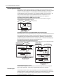
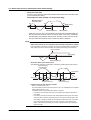
The following is a block diagram of analog retransmission:
Remote input/control module relay
Measurement input/
computation input
Manual operation
Control input
PV/SP/control output
Internal switches
11
Communication data
Analog retransmission computation section
12
Automatic (AUT)
Manual (MAN)
Output data created
Output
13
OUT
14
IM 04L31A01-03E
1-7
1.2 Control Function Overview
The order of processing for PID computation and analog retransmission is as follows:
Input value, data used
in computation
(newest value)
Processing of all
control loops
Start control task
Previous PV, previous
SP, previous output
value (PID computation)
PID
computation
Previous output value
(analog retransmission
output)
Processing of all
Analog retransmission
computation
analog retransmission
loops
Display/recording/
Processing of all loops
terminal output
PV, SP output value
(PID computation)
Output value (analog
retransmission output)
Stop control task
Data that can be used in the analog retransmission equation are as follows:
• Measured input data, measured computation data, internal/external control data, and
communication input data.
• Constants (constants used in measurement computations can not be used)
• Control input data
• Control output module, expansion module DIO, and remote input for measurement
• Internal switches
Computation Error
You can specify the output method when a computation error occurs, such as when an
overrange occurs on the computed results of analog retransmission.
Over: 105% of span
Under: –5% of span
Display/Recording of Analog Retransmission
The output value of analog retransmission is displayed/recorded as the OUT value of the
loop specified for analog retransmission. PV and SP are not displayed or recorded.
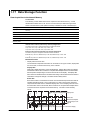
Internal Switches (Style Number S3 or Later)
Internal switches are software switches that are not output externally, and are used only
for internal processing. The switches have the following uses.
• The same output destination as the output relay
Control alarm, measurement alarm, measurement computation alarm, time event, PV
event, program pattern end signal, logic computation output.
• DIO operation monitoring function
• Use of computation data in the PV/SP computation and the analog retransmission
equation
• Assignment of actions to changes in the status of the internal switches
• Reads the operation ON/OFF and internal switch statuses using the communication
function.
The status of the internal switches is “nonhold.”
1-8
IM 04L31A01-03E
1.2 Control Function Overview
1
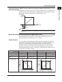
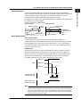
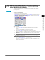
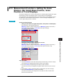
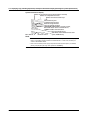
DIO Operation Monitoring Function (Style Number S3 or Later)
When DO01 is assigned to SW01
Internal switch SW01
MAN
AUTO
2
3
4
When DO003 is assigned to the
ON signal of SW02, and DO004
is assigned to the OFF signal
5
Internal switch SW02
AUTO
ON
DO001
Explanation of Functions
Internal Switches and DIO Operation Monitoring Function
Since the internal switches are used exclusively for internal processing, the status of the
switches cannot be confirmed externally. With the DIO operation monitoring function,
you can output the status of the internal switches by assigning a DO to the internal
switch. You can output the ON and OFF statuses of the internal switches to separate
DOs. Also, you can switch between Auto and Manual operation modes. When in Auto
mode, the status of the internal switches is output. When in Manual mode, you can
manually switch between DO ON(1) and OFF (0). Internal switch output has priority over
alarm output and event output. If the same DO is assigned to an internal switch and an
alarm output, alarms cannot be output.
DO003
MAN
6
OFF
DO004
In the above cases, even if D001, DO003, and DO004 are specified for alarm output, the
alarm signal is not output. However, FAIL and self diagnosis output take priority over the
internal switch status output.
7
8
9
10
11
12
13
14
IM 04L31A01-03E
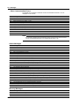
1-9
1.2 Control Function Overview
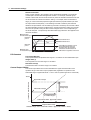
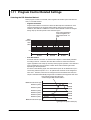
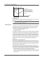
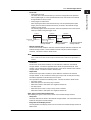
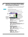
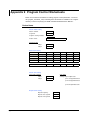
Program Control (Optional Function)
This function is used to ramp-up or ramp-down the SP according to a program pattern.
You can set multiple program patterns (up to 4 on the /PG1 option and up to 30 on the
PG/2 option) and switch among them according to the operating condition. A program
pattern consists of multiple program segments. With style number S3 or later, you can
execute a program pattern while a separate program pattern is executing as long as the
operating loops do not overlap.
There are two methods in selecting the PID constant in program control. One is the
“segment PID method” in which the PID constant is switched every segment according to
the program pattern setting; the other is the “zone PID method” in which the PID
constant is automatically switched according to the PV. The “segment PID method” is
used when a different PID constant is required in the same PV region when the
temperature is rising and when the temperature is falling.
Segment PID method
The PID constant of PID No. 1
is used in the 5th segment (SEG5).
PV
1000.0
500.0
0.0
SEG1
SEG2
SEG3
SEG4
No.2 PID
SEG5
No.1 PID
SEG6
SEG7
No.3 PID
Setting the Operation for Program Control
Settings include the number of repetitions of the program pattern (repeat function), delay function
(wait function) for the case when the PV cannot follow up the SP, and alarm output/event output
assignments (contact output can be assigned) according to the program progression.
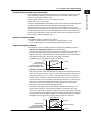
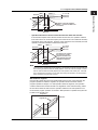
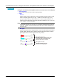
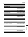
Operation Mode during Program Control
The following 4 types of operation modes are available.
• Program operation mode
Condition in which control is carried out according to the program pattern.
• Hold operation mode
Condition in which the change in the SP according to the program pattern is forcibily
paused through key operation or other factors.
• Reset mode
Condition in which program operation of all loops is stopped. All event outputs are
cleared (off).
• Local operation mode
If you switch to local operation mode even during program control, fixed-operation is
perfomed acording to the SP set locally.
RESET or
all loop STOP
Local operation
mode
Reset mode
RUN
PRG RUN
PRG RUN
PRG
RESET, program end,
or all loop STOP
Program operation
mode
LOC or program
LOCAL end
Release HOLD
Hold operation mode
HOLD
During program control
Since the remote input cannot be used for the SP during program control, there is no
remote/local switching operation.
1-10
IM 04L31A01-03E
1.2 Control Function Overview
1
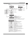
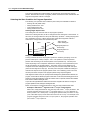
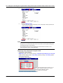
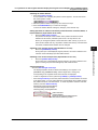
Flow of Setup Procedure
Basic settings include the following
parameters.
Power ON
Basic settings
PID control or
ON/OFF control?*
Basic settings
"Control Output Type"
Set SP
→ Section 1.3
PV input related settings
→ Section 1.4
* Set in
PID control of basic control settings
ON/OFF control
Basic control settings
Set SP
→ Section 1.6
Set relay hysteresis
Set PID parameters
→ Section 1.7
Set other control
parameters
Set alarm-related
parameters
Set alarm-related
parameters
Start a test run
Section 1.9
Explanation of Functions
Below is a standard flow of setup procedure in executing control for the first time using
auto operation.
2
3
4
Contact input/output
related settings
→ Section 1.5
5
→ Section 1.10
6
Operating condition
Adjust control
Start actual operation
•
•
•
•
7
Auto tuning
Manual tuning → Section 1.12
Control output suppression → Section 1.8
Other adjustments
(Parameters that cannot be changed
during operation → section 6.1)
8
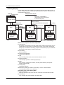
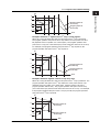
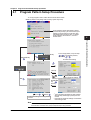
When using program control, set the items that include “Program control: On” in “Basic
control settings” indicated above. Then, carry out the following settings in addition to
“Target setpoint/PID parameter settings.”
Settings for program control
Pattern initial setting
Wait action setting
Wait action setting:
Set wait zone off/on, wait zone settings, and timer.
Pattern start setting
Pattern start setting:
Set starting target setpoint and start code (operation
start condition).
Event setting
Repeat action setting
Event output setting
Auto message printing/
program display position
setting
IM 04L31A01-03E
→ Section 1.11
Pattern initial setting:
Set the pattern numbers, pattern off/on, number of
segments used, segment assignment method,
edit segment number, and loop number.
Program pattern setting
9
10
11
Program pattern setting:
Set segment numbers, ramp/soak, final target setpoint,
segment time, ramp-rate-time unit, ramp-rate, segment
PID group numbers, operation at the time of segment
switching, wait operation type, and wait numbers.
Event setting:
Set event types, loop number/type/setpoint (only when
PV event is selected), time event ON/OFF, ON time/
OFF time (only when time event is selected), and hysteresis of
PV event..
Repeat action setting:
Set the repeat function, number of repetitions, start
segment number, and end segment number.
12
13
14
Event output setting:
Set the event type, relay output ON/OFF, and relay
output number.
1-11
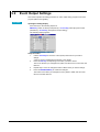
1.2 Control Function Overview
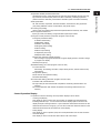
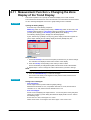
Switching Displays
Control-related settings are entered in basic setting mode and control setting mode. In
addition, settings common to control and measurement are entered in the common and
measurement setting mode.
Display Transition Diagram
Power ON
Operation mode
[End] soft key -> DISP/ENTER key
(This operation saves the settings made
in the basic setting mode.)
Operation display
MENU key or ESC key
MENU key
ESC key
Common and measurement setting mode
[Set mode]
Control setting mode
[Setting mode (Control)]
MENU key
Press the FUNC
key for 3 s
Menu
Soft keys
MENU key or
ESC key
Soft keys
MENU key or
ESC key
#1 to #9 when program control
is ON.
Menu
Soft keys
Setup display
(#1 to #11)
Setup display
(#1 to #8*)
*
Press the FUNC
key for 3 s
Menu
Basic setting
mode
ESC key
Setup display
(#1 to #12**)
**
#1 to #11: Basic common and
measurement settings
#12: Basic control settings
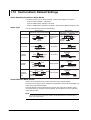
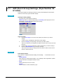
Basic Control Setup Items in Basic Setting Mode
#1 Control action
PID number, control period, zone PID, restart mode, restart mode (program) (only on
models with the control option), initial PID, auto tuning, control mode, method (only
during loop control with PV switching), program control ON/OFF (only on models with
the program control option), and PID control mode.
#2 Input setting
Burnout and RJC.
#3 Contact input-registration
Contact input registration
#4 AUX
Remote setting, alarm mode, and SP number selection source.
#5 Output processing
Control output, cycle time, and analog-output type
#6 Relay
FAIL ON/OFF, self diagnosis ON/OFF, and relay action/behavior (energize/deenergize, hold/nonhold)
#7 Tuning setting
Tuning item selection
#8 External loop setting (For details on the settings, see the CX1000/CX2000
Communication Interface User’s Manual.)
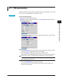
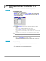
Setup Items in the Control Setting Mode
#1 Control input range
Input type, mode, type, range, span, scale, unit, square root, low-cut, bias, filter, and ratio.
#2 Control alarm
Type, standby, relay output ON/OFF, and alarm value
1-12
IM 04L31A01-03E
1.2 Control Function Overview
2
3
4
5
6
7
8
9
10
11
12
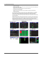
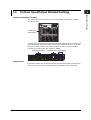
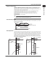
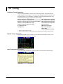
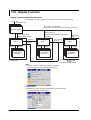
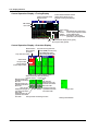
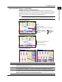
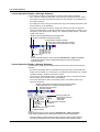
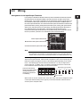
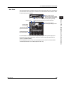
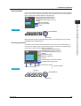
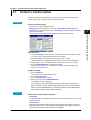
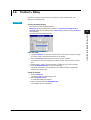
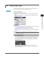
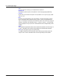
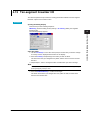
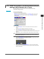
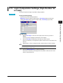
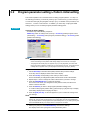
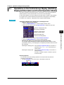
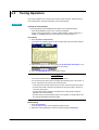
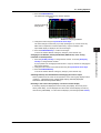
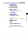
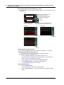
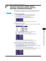
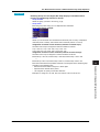
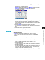
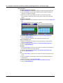
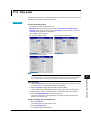
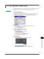
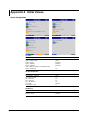
Control Operation Display
In operation mode, the following control operation displays can be shown.
• Control group display
This display is used to monitor the control status of multiple loops simultaneously
including external loops. You can select from three display styles as shown in the
display example in the figure below. If you include the measurement channels for the
measurement function in the group, you can also monitor the measured values on the
measurement channels at the same time on this display.
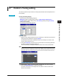
• Tuning display
This display is used to optimize (tune) the control parameters such as PID constants.
• Overview display
This display is used to monitor the alarm status of all control loops.
IM 04L31A01-03E
1
Explanation of Functions
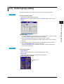
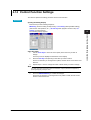
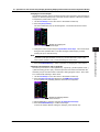
#3 Operation-related parameters/Zone PID
Suppressing function, ramp-rate-time unit, SP ramp-down-rate/SP ramp-up-rate, tag,
tag comment, reference point (when zone PID is selected), switching hysteresis
(when zone PID is selected), and reference deviation (when zone PID is selected).
#4 PID parameters
SP, PID constant, output limit, shutdown ON/OFF, manual reset, relay hysteresis
(only during ON/OFF control), reverse/direct, and preset output.
#5 Control group setting
Group name, kind (internal loop/external loop/measurement channel), and number.
#6 Ten-segment linearizer I/O
Input type, mode, and biasing or approximation input/output values.
#7 Program control paramters (only when program control is ON)
#1 Program parameter setting
#1 Pattern initial setting
#2 Wait action setting
#3 Pattern start setting
#4 Program pattern setting
#5 Event setting
#6 Event output setting
#7 Hysteresis (PV event)
#8 Repeat action setting
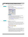
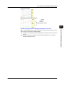
#2 AUX (Auto message, Display position)
Auto message for program Run/Reset, Program display position, and Auto change
to program run display.
#3 AUX (Event group)
#8 Detailed setting (“#7” when program control is OFF)
#1 Control function
SP tracking, PV tracking, SP limiter, output velocity limiter, and anti-reset windup
auto/manual.
#2 Hysteresis (Alarm)
#3 DIO monitor and operation setting
#4 DI/DO label setting
#9 Control math setting (“#8” when program control is OFF)
#1 PV/SP math, Retransmission
#2 Logic math (#1 when both PV/SP computation and analog retransmission are
inactive.)
#3 Constant (#2 when both PV/SP computation and analog retransmission are
inactive.)
1-13
13
14
1.2 Control Function Overview
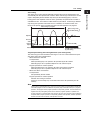
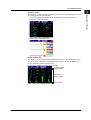
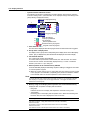
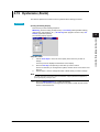
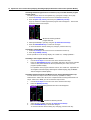
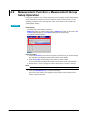
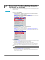
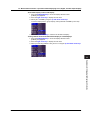
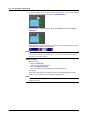
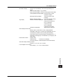
• DI/DO status display
Displays the ON/OFF status of the current contact input (DI) and contact output (DO).
• Internal switch status display
Displays the current ON/OFF status of the internal switches.
• Control action summary display
Displays a log of control actions such as operation run/stop and auto/manual
operation switching.
On models with the program control function option, additional displays are available
such as 1) the program control display, which can show the pattern and current PV
accumulated on the screen during program operation and 2) the program event
summary display, which shows a log of time events and PV events that occurred during
program operation.
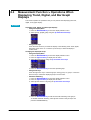
Displays common with the measurement function include: 1) the alarm summary display, which
shows a log of alarm occurrence status and 2) the memory summary display, which shows the
file information of the internal memory. In addition, the values of PV, SP, and OUT can be
assigned to channels, and the trends of these channels can be displayed along with the trends of
measurement channels on the trend display of the measurement function.
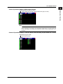
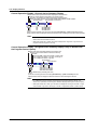
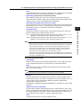
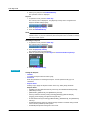
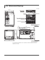
Display Examples
• Control group display
Controller style
• Tuning display
Faceplate style
• Overview display
• Control operation summary display • Internal switch status display
1-14
Hybrid style
• DI/DO status display
• Program control display
IM 04L31A01-03E
1.2 Control Function Overview
1
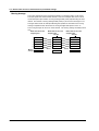
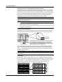
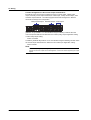
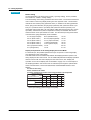
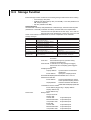
Saving Data
Floppy disk
CX
1
2
Zip disk
6
11
16
21
26
7
12
17
22
27
8
13
18
23
28
4
9
14
19
24
29
5
10
15
20
25
30
3
4
ATA flash memory card
5
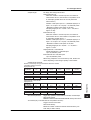
The following communications functions are available. For a description on the handling
of the communications function and the software “DAQSTANDARD for CX” that comes
with the package, see the respective manuals.
Communications with Controllers
The CX1000 can communicate with UT Series Controllers made by Yokogawa M&C
Corporation to transmit/receive control parameters and receive PV data. Up to four
external loops can be constructed.
CX
4
5
6
7
8
6
11
16
21
26
7
12
17
22
27
8
13
18
23
28
9
14
19
24
29
10
15
20
25
30
3
3
DISP
Communications
2
2
/ENTER
• Control setup data
• Measurement setup data
• Measured data
1
Explanation of Functions
Acquisition to the Internal Memory
Along with the measurement data, the data of SPs, PVs and OUT, and event information
for control are acquired to the internal memory.
Saving Data to the External Storage Medium
You can save the data acquired in the internal memory to an external storage medium
(floppy disk, Zip disk, or ATA flash memory card).
DISP
/ENTER
9
Controllers
10
Up to four units (four loops)
Communications with PLCs
The CX1000 can carry out ladder communications between PLCs (sequencers).
PLCs (such as the FA-M3 by YOKOGAWA)
11
12
CX
CX
13
1
2
3
4
5
6
11
16
21
26
7
12
17
22
27
8
13
18
23
28
9
14
19
24
29
3
10
15
20
25
30
4
5
1
DISP
/ENTER
2
6
11
16
21
26
7
12
17
22
27
8
13
18
23
28
9
14
19
24
29
10
15
20
25
30
DISP
/ENTER
Up to 32 units
14
Communications with PCs
The CX1000 can communicate with PCs.
PC
CX
1
2
3
IM 04L31A01-03E
6
7
8
4
9
5
10
11
16
21
26
12
17
22
27
13
18
23
28
14
19
24
29
15
20
25
30
DISP
• Modbus master/slave
• Dedicated protocol communications
with the PC (Command communications)
• Display settings/data of the CX using
“DAQSTANDARD for CX”
/ENTER
1-15
1.3
Basic Settings of Control
PID Group Number
You can set up to eight groups of control parameters (“PID parameters” on the setting
display) that you wish to change collectively through control. You set the number of
groups to be used from 1 to 8. For example, if you set a value of 4, the selectable PID
numbers will be 1 through 4. The parameters that are included in a single control
parameter group vary depending on the control method (“Control output” in the settings).
During PID control:
SP, PID constant, output lower/upper limit, shutdown ON/OFF
(only when outputting 4-20 mA of current), manual reset, reverse/
direct, and preset output
During ON/OFF control: SP, relay hysteresis, reverse/direct, and preset output
Control Period
The following control periods can be selected:
250 ms (initial value), 500 ms, and 1 s.
The control period is common to all loops. When the A/D integral time is set to 100 ms,
the control period is fixed to 1 s.
The scan interval of control PV input is the same as the control period.
PID Selection Method (Zone PID ON/OFF)
Select either one from below. When program control is ON on models with the program
control option, the selection is between the segment PID method (zone PID OFF) and
the zone PID method.
• Target setpoint selection method (zone PID: OFF) (initial value)
In the target setpoint selection method, the operator can switch up to 8 SPs as
necessary. There are two methods in switching the SPs. One method is to specify
the SP number (SPs are registered to PID numbers (= SP numbers) along with PID
constants and other parameters) using keys on the front panel. The other is to use
external contact input or communications. The SP can be switched at any time.
During switching, the setpoint ramp-up-rate or setpoint ramp-down-rate setting is
activated. In addition, when a switch is made, control computation is performed using
the PID constant group that corresponds to the SP at that point.
PV
Rise according to
the setpoint
ramp-up setting
SP3
(No.3PID)
Fall according to
the setpoint
ramp-down setting
SPn: SP number
SP2
(No.2PID)
SP1
SP1
(No.1PID)
Switch from SP1 to SP3
1-16
Rise according to the
setpoint ramp-up setting
Time
Switch from SP3 to SP1 Switch from SP1 to SP2
(No.1PID)
IM 04L31A01-03E
1.3 Basic Settings of Control
Maximum value of
measurement span
If the current PV here,
Reference point 5 control using thePID
constant of No. 4.
Reference point 4
1
Explanation of Functions
• Zone PID method
In the zone PID method, the measurement span is divided into a maximum of seven zones
using reference points. The optimum PID constant is preassigned to each zone, and the
PID constant (in actuality, other control parameters that are registered using the PID
number are included) is automatically switched according to the PV.
The number of reference points that can be specified is “PID group number – 2.” As shown in
the figure below, if the PID group number is 7, the number of reference points is 5. If the
number of reference points is 5, there are 6 zones. For example, if zones 1 through 6
correspond to PID numbers 1 through 6 and if the PV is within the zones of reference points 3
and 4, the control parameters of PID number 4 are selected. The control parameters of PID
number 7, which cannot be assigned to a zone, are selected when the deviation between the
SP and PV becomes greater than the preset reference deviation.
2
3
4
No.6 PID
5
No.5 PID
No.4 PID
Reference point 3
No.3 PID
Reference point 2
Reference point 1
Minimum value of
measurement span
Change in the
PV.
6
No.2 PID
No.1 PID
Restart and Restart for Program Control
7
Select how the CX1000 is to behave when an extended power failure occurs during control
operation (power failure period of 5 s or more) and the power recovers.
• Continue (initial setting):
Continue the operation before the power failure occurred.
• Manual operation:
Start from the manual operation condition.
• Auto operation (only during fixed-point operation):
Auto operation by continuing the operation before the power failure occurred.
• Reset (only during program operation):
Stop the program operation.
8
9
10
Note
If the duration of the power failure is less than or equal to 2 s (a short power disruption), the
operation before the disruption continues. If the duration is between 2 to 5 s, the behavior for a
short power disruption or an extended power failure is carried out depending on the condition.
11
Initial PID
Select whether the initial PID constant in PID parameter settings (see page 1-31) is
optimized to temperature control, pressure control, or flow control. Below are the initial
values of PID constants.
Initial values for temperature: P = 5.0%, I = 240 s, and D = 60 s.
Initial values for pressure/flow: P = 120.0%, I = 20 s, and D = 0 s.
12
13
Control Mode
The following four control modes are available. The mode is selected for each control loop.
• Single-loop control
Basic control consisting of a single system of controller CPU.
14
PV
SP
PID
OUT
IM 04L31A01-03E
1-17
1.3 Basic Settings of Control
• Cascade control
Control consisting of two systems of controller CPUs that uses the primary control
output as the secondary control SP. Continuous PID control is only possible for
primary control.
PV2
PV1
SP
PID
PID
OUT
• Loop control with PV switching
Single-loop control that switches between two PV inputs (PV1 and PV2) according to
the following conditions.
PV1 PV2
SP
PID
OUT
Input Switching Condition ([Method] on the setting display)
• Auto switching according to the PV range ([Range] on the setting display)
Switches PV inputs (PV1 and PV2) automatically according to the preset “PV
switching low-limit” and “PV switching high-limit” as shown in the following figure.
However, PV1 must be less than PV2.
PV
PV range high limit
PV2
PV switching high limit
PV switching low limit
PV range low limit
Process value according
to the equation
PV1
The PV value is computed using the following equation when “PV switching lower limit
< PV1 ≤ PV switching upper limit” and “PV switching lower limit ≤ PV2 < PV switching
upper limit.”
Process value = 1–
PV input 1 – PV switching low limit
× PV input 1+
PV switching high limit – PV switching low limit
PV input 1 – PV switching low limit
× PV input 2
PV switching high limit – PV switching low limit
• Auto switching according to the PV switching upper limit ([PVHigh] on the setting display)
The preset “PV switching upper limit” and PV1 are compared. Auto switching is
performed according to the following conditions. The switching hysteresis is
approximately 0.5% of the PV range span.
When PV1 ≤ PV switching upper value: Switch to PV1
When PV1 > PV switching upper value: Switch to PV2
• Switching through control input ([Signal] on the setting display)
Input is switched using “PV switching (loops 1 and 2)” (see page 1-26) as follows:
Contact input is OFF: Switch to PV1. Contact input is ON: Switch to PV2.
Analog Retransmission
Outputs the specified computed result instead of the computed PID value from the
control output terminal. In control setting mode, you can set the equation, output span,
unit, and method of processing computation errors for the loop specified for analog
retransmission. Unlike the 3 control modes above, control functions such as upper/lower
output value and preset output are not supported.
Program Control ON/OFF (only on models with the program control option)
Select whether to use the program control function. For a description on the settings for
program control, see section 1.11, “Program Control Related Settings.”
1-18
IM 04L31A01-03E
1.3 Basic Settings of Control
1
PID Control Mode
Type of PID
Control Mode
Control Method
PV derivative type PID
During operation in local
mode or auto mode
(only the primary side
during cascade control)
With bumps in the control
output at the time the SP
is changed
Standard PID
control mode
(Initial value)
Deviation derivative
type PID
During operation in remote
mode (secondary side
during cascade control)
With bumps in the control
output at the time the SP
is changed
PV derivative type PID
During operation in local
mode or auto mode
(only the primary side
during cascade control)
Explanation of Functions
There are two PID control modes: standard PID control mode and fixed-point control mode. To
control the output so that the PV reaches the new SP quickly after the SP is changed, select
“standard PID control mode.” To perform a continuous fixed-point control, select “fixed-point
control.” As shown in the figure below, the control behavior varies depending on the selected
PID control mode. There are two control methods: PV derivative type PID control method and
deviation derivative type PID control method. As shown in the figure below, the control method is
automatically selected. In addition, the presence or absence of the control output bump at the
point of change of the SP is automatically selected. When performing program control in
standard PID control mode on models with the program control option, deviation derivative type
PID control is used during operation (except during hold and soak) and on the secondary loop of
cascade control. For all other cases, PV derivative type PID control is used.
2
3
4
Description of the Control Operation
Employs a PV derivative type PID so that the output reaches
the new SP quickly after the target setpoint is changed. In PV
derivative type PID, the proportional terms (P) that are
proportional to the deviation that occurred due to the SP change
are output immediately, forcing the process value to quickly reach
the new SP.
SP
5
6
7
PV
OUT
By applying the derivative term (D) against the deviation that
occurs due to minute changes in the program pattern, the process
value quickly tracks the program pattern.
8
9
SP
PV
OUT
Use this function on continuous fixed-point control, if you do not
wish to disturb the PV caused by the sensitive reaction of the
control output (OUT) at the time the SP is changed.
In the case of "PV derivative type PID + no control output bumps,
" the output value (OUT) does not drastically change at the time
the SP is changed. The deviation is gradually eliminated using
only the integral term (I) against the deviationthat occurs.
10
11
Without bumps in the
control output at the time
the SP is changed
12
SP
Fixed-point
control mode
PV derivative type PID
During operation in remote
mode (secondary side
during cascade control)
PV
OUT
Use this function on the secondary loop of cascade control.
A stable control output is achieved without sensitively reacting to
the output of the primary loop.
14
PV
With bumps in the control
output at the time the SP
is changed
SP
OUT
IM 04L31A01-03E
13
1-19
1.3 Basic Settings of Control
Control Output
Select the type of control output from the following. The type can be selected for each loop.
• Time proportional PID relay contact output
• Time proportional PID voltage pulse output
• Current output (continuous PID control output)
• On/off control relay contact output
Time Proportional PID
The result of PID computation is output using a pulse width of an ON/OFF signal that is
proportional to the time. The pulse width is calculated using the following equation with
the cycle time (control output period, see next section) taken to be 100%.
Pulse width = Control output (%) × cycle time
You can select relay output or voltage pulse for the output type.
Current Output (Continuous PID Control Output)
The result of PID computation is output using a current (analog signal) that is
proportional to the computed PID value. There are four types of output current.
On/Off Control Relay Contact Output
The on and off signals are output using a relay according to the polarity of the deviation
between the SP and PV.
Cycle Time
Set the cycle time (control output cycle) for the time proportional PID in the range of 1 s
to 1000 s. Setting a short cycle time enables precise control. However, the life of the
output relay and the input contact on the control element may be shortened, because the
number of ON/OFF operations increases. In general, the cycle time is set around 10 s to
30 s for relay output. You can select the cycle time for each loop.
ON
OFF
When the cycle time is long
ON
Ratio of the
ON time
OFF
When the cycle time is of
medium length
ON
ON
OFF
When the cycle time
is short
0.0
50.0
Output display value
OFF
100.0
Cycle time
Selecting the Analog Output
Select the type of output current when current output is used from the following:
4-20 mA, 0-20 mA, 20-4 mA, and 20-0 mA.
1-20
IM 04L31A01-03E
1.4
PV Input Related Settings
1
Input Type
Select the input source for making input range related settings from the following. Select
“RemoteSP” when setting the remote input when you are performing remote/local
switching of the SP. When using program control, “RemoteSP” cannot be selected
because remote input is not possible.
• During single-loop control or cascade control: PV1/RemoteSP
• During loop control with PV switching: PV1/PV2/RemoteSP/PVrange
Set “process value 1” (PV1) and “process value 2” (PV2). “PVrange” is used for “loop
control with PV switching” when the input range of two PV inputs (PV1 and PV2) is
different and PV range conversion (see page 1-23) is to be performed. When set to “PV
range,” “PV upper-/lower-limits,” “unit,” and “PV switching lower/upper limits” (“PV lowerlimit” if the input switching method is “PV High”) are set in place of the following settings.
Measurement Mode
Select from the following according to the type of input.
TC (thermocouple), RTD (resistance temperature detector), scale (linear scale), and 1-5 V.
Select scale when scaling the input signal to values with an appropriate unit for the
application. If you select scale, set the lower and upper limits.
Type (setting only when measurement mode is set to “scale”)
Select the type of input signal from “Volt,” “TC” (thermocouple), and “RTD” (resistance
temperature detector.”
Range
Set the range (thermocouple or resistance temperature detector type) that matches the
input signal type. This setting determines the measurement range (measurable range).
• Thermocouple
R, S, B, K, E, J, T, N, W, L, U, PLATINEL, PR40-20, and W3Re/W25Re.
• Resistance temperature detector
Jpt100 and Pt100.
• Voltage
Standard signal: 1-5 V (when “measurement mode” is set to “1-5 V”)
Current voltage: 20 mV, 60 mV, 200 mV, 2 V, 6 V, 20 V, and 50 V.
Span
Set the “measurement span,” the actual range of control (upper limit and low limit), within
the minimum and maximum values of the measurement range.
Unit
You can enter the unit using up to 6 alphanumeric characters.
PV Correction
Input Filter
The input filter can be used to eliminate noise when harmonic noise is included in the PV input
such as in current signals and pressure signals. The input filter is first-order-lag computation. The
larger the time constant (parameter setting), the stronger the noise elimination function becomes.
The input filter is also used for the improvement of the controllability and for phase correction.
The time constant of the input filter can be changed during operation as an operation parameter.
Selectable range: OFF (no filter) or 1 to 120 s (initial value is OFF)
Raw input
IM 04L31A01-03E
Filter time constant:
small
Filter time constant:
large
1-21
Explanation of Functions
Input Range
2
3
4
5
6
7
8
9
10
11
12
13
14
1.4 PV Input Related Settings
Bias
This function is used to add a constant value (bias value) to the PV and use the result in
the display of the PV and control.
PV input value
+
Bias value
= Process value in the instrument
This function can be used in a case when the PV is less than the true value by a
constant amount due to the physical circumstances of the detector. For example, the
atmospheric temperature inside a furnace can be measured and substituted for the
material temperature. This function can also be used to make minute adjustments when
the displayed value is within the allowable precision range but small deviation exists
between other instruments and you wish to align it.
Selectable range: –100.0% to 100.0% of the measurement span (the initial value is 0.0%)
Ten-segment Linearizer Biasing Function
This function is used when you wish to correct the input value due to the deterioration of
the sensor. In the ten-segment linearizer biasing function, the output value (b) is the
corrected value obtained by adding the bias at numerous arbitrary points (up to 11 points
can be specified) against the input value (a), as shown in the figure below. For
definitions of the engineering units (EU and EUS), see appendix 8, “Explanation of
Engineering Units (EU and EUS).”
Selectable range of input values: EU (–5.0% to 105.0%) of the measurement span (the
initial value is 0.0%)
Selectable range of output values: EUS (–100.0% to 100.0%) of the measurement span
(the initial value is 0.0%)
Output
(b)
Corrected value
(sum of the actual input
and the ten-segment
linearizer bias)
Actual input
Ten-segment linearizer bias
n.b4
n.a2
n.a4
Input
(a)
Ten-segment Linearizer Approximation
This function is used when the relationship between the input signal value and the value you wish
to measure is not linear such as the level meter and the volume of a spherical tank. In the tensegment linearizer approximation function, you can set the output value (b) to an
arbitrary value with respect to the input value (a) of an arbitrary point (up to 11 points can
be specified), as shown in the figure below. For definitions of the engineering units (EU
and EUS), see appendix 8, “Explanation of Engineering Units (EU and EUS).”
Selectable range of input value: EU (–5.0% to 105.0%) of the measurement span (the
initial value is 0.0%)
Selectable range of output values: EU (–5.0% to 105.0%) of the measurement span (the
initial value is 0.0%)
1-22
IM 04L31A01-03E
1.4 PV Input Related Settings
1
Explanation of Functions
Output
(b)
2
Ten-segment linearizer
approximation
3
4
Input
(a)
5
Square-root Computation of PVs
The square-root function is used in the case such as when the differential pressure
signal of a restriction flowmeter such as an orifice or a nozzle is converted to a flow
signal. You can also set the low-signal cutoff point for the square-root computation.
Square-root computation ON/OFF setting: ON or OFF (the initial value is 1.0%)
Selectable range of the low-signal cutoff of the analog input: 0.0 to 5.0% (the initial value
is OFF)
6
7
100.0%
8
9
Slope: 1
10
0.0%
Low-signal
cutoff point
(0.0 to 5.0%)
Input
100.0%
11
PV Range Conversion (only during loop control with PV switching)
The PV range conversion is a function used to determine the PV range of the control
function when the measurement range of the two input signal is different for the loop
control with PV switching. For example, if the input range of the first input is 0 °C to 500
°C and the input range of the second input is 300 °C to 1000 °C, the PV range
conversion is used to convert the PV range of the control function to 0 °C to 1000 °C.
12
13
PV range
PV range of PV input 2
14
PV range of
PV input 1
0
IM 04L31A01-03E
300
500
1000 °C
1-23
1.4 PV Input Related Settings
PV Tracking ON/OFF
The PV tracking function is used to prevent radical changes in the PV.
When the PV tracking function is enabled (ON), the SP is forced to match the PV once in
the following cases.
• When powering up.
• When switching from manual (MAN) operation mode to auto (AUTO) operation mode.
• When switching from operation stop to operation run.
• When switching the SP number.
The SP is matched against the PV once, and then returns to the original SP according to
the “target setpoint ramp-rate (rate of change)” that is specified separately. When using
the PV tracking function, make sure to set the SP ramp-rate (rate of change). The ramprate is 0 when it is OFF. Consequently, the PV tracking function does not operate in this
case. PV tracking function ON/OFF setting: ON or OFF (the initial value is OFF)
• When PV tracking is OFF
SP
PV
MAN
AUTO
Time
Mode switching
• When PV tracking is ON
Follows the target setpoint
ramp-rate
SP
PV
MAN
AUTO
Mode switching
Time
Burnout
When the PV input is a thermocouple or standard signal, a burnout action can be
specified. When a burnout is detected, the PV is fixed to positive overrange (when the
burnout detection action is set to “UP”) or negative overrange (when the burnout
detection action is set to “DOWN”), and the control output is set to preset output.
Reference Junction Compensation
You can select whether to use the internal reference junction compensation function of
the CX1000 or an external reference junction compensation function. When using an
external reference junction compensation, set an appropriate reference junction
compensation voltage. For example, if the reference junction temperature of the external
reference compensation is T0 °C, set the reference compensation junction voltage to the
thermoelectromotive force of the 0-°C reference of T0 °C.
1-24
IM 04L31A01-03E
1.5
Contact Input/Output Related Settings
1
The contact signal is input or output from the control output terminal block indicated in
the following figure.
Explanation of Functions
Contact Input/Output Terminal
2
3
4
Control output
terminal block
5
As shown in the following figure, contact input terminals (DIGITAL IN) and contact output
terminals (DIGITAL OUT) are arranged on the control output terminal block. There are
two types of contact outputs: relay output and transistor output. For the connection
procedure of the signal wires, see section 2.3, “Wiring”.
Relay contact output
NO
NC
C
NO
NC
C
CTRL OUT
2
NO
C
1
NO
C
7
Transistor output Contact input
DIGITAL OUT
LOOP2 LOOP1
DIGITAL OUT
DIGITAL IN
5
6
C
4
5
6
6
LOOP2 LOOP1
mA
mA
PULS
PULS
C
C
3
4
C
1
2
3
8
CTRL OUT
Contact Input
Prescribed operation such as stop/run operation can be performed using contact inputs.
There are six contact inputs, and numbers DI001 to DI006 are used to select them.
9
10
11
12
13
14
IM 04L31A01-03E
1-25
1.5 Contact Input/Output Related Settings
Contact Input Information Registration
You can select the information that is registered to the contact input from the following.
Name of Action
Detection
Action
Stop all loop control operation
Start all loop control operation
Stop/run control (loops 1 and 2)
Remote/local (loops 1 and 2)
Trigger
Trigger
Edge
Edge
Auto/Man operation
(loops 1 and 2)
Cascade switching
Auto operation
Manual operation
Set target setpoint bits 0 to 3
Start program operation
Edge
Trigger
Trigger
Trigger
Trigger
Trigger
Reset program operation
Trigger
Hold
Trigger
Advance
Trigger
Set pattern number 0 to 4 bits
Trigger
Input switch contact
(loops 1 and 2)
Start/Stop
Trigger
Edge
Edge
Trigger
Alarm ACK
Trigger
Time adj
Math
Trigger
Edge
Math reset
Trigger
Manual sample
Trigger
Load setup data 1 to 3
Trigger
Messages 1 to 8
Trigger
Snapshot
Trigger
Stops the operation of all internal loops.
Starts the operation of all internal loops.
Starts/stops the operation of each internal loop.
Switches the local/remote operation modes of each
internal loop.
Switches the auto/manual operation modes of each
internal loop.
Switches the internal loops 1-2 to cascade operation.
Switches the internal loops 1-2 to auto operation.
Switches the internal loops 1-2 to manual operation.
Switches the SP to the specified binary value.
Starts the program operation (only on models with the
program control option).
Resets the program operation (only on models with the
program control option).
Holds the program operation (only on models with the
program control option).
Advances the program operation (only on models with the
program control option).
Switches the program pattern number to the specified
binary or binary-coded decimal value (only models with the
program control option).
Switches the PV input (PV1, PV2) of each internal
loop during loop control with PV input switching.
Starts/stops data acquisition to the internal memory.
Trigger used to start acquiring event data to the
internal memory (valid only when “event data” is
specified to be acquired to the internal memory and
the trigger used to start the acquisition is set to
“external trigger”).
Clears alarm display/relay output (valid only when the
alarm indicator or output relay behavior is set to “hold”).
Adjusts the internal clock to the nearest hour.
Starts/stops computation (only on models with the
computation function (/M1)).
Resets computed data of measurement channels
(Resets the computed value to 0. Only when
computation is stopped on models with the
computation function option).
Acquires instantaneous values of all channels to the
internal memory.
Loads the setup data file saved to the external storage
medium.
Displays message 1 to 8 on the trend display and
stores the message to the internal memory.
Saves the screen image data to the external storage
medium.
Method of Detecting Contact Inputs
The above operations are carried out on the rising or falling edge of the contact signal
(edge) or the ON signal lasting at least 250 ms (trigger). The remote signal rises when
the contact switches from “open to closed” and falls when the contact switches from
“closed to open.” For open collector signals, the remote signal rises when the collector
signal (voltage level of the input terminal) goes from “high to low” and falls when the
collector signal goes “low to high.”
Trigger
Rising and falling edges
Rising
1-26
Falling
250 ms or more
IM 04L31A01-03E
1.5 Contact Input/Output Related Settings
1
Note
•
•
•
Explanation of Functions
•
For a description on how to register contact inputs, see “Setup Items” of section 4.3,
“Basic Control Settings > Contact Input-Registration.”
On models with the measurement alarm option terminal block /A6R or /A4FR, the actions from
“Start/stop” to “Snapshot” can also be assigned to the measurement remote input. For a
description on the assignment of actions to the measurement remote input, see “Measurement
Remote Input” on page 1-100.
If the same action is performed using keys of the CX1000, communications, and contact
input, the newest operation/input is valid regardless of the method. This is also true
between contact inputs and measurement remote inputs.
If a program start trigger activates through contact input during program hold, hold mode is
cleared.
2
3
4
Contact Output (FAIL Output, Self Diagnosis Output, and Event Output)
Output Terminal Selection
There are six contact outputs, and numbers DO001 to DO006 are used to select them.
Setting the Relay Action/Hold
Set whether to energize or de-energize the output relay when outputting failure detection
found by FAIL or self diagnosis and events. In addition, set whether the relay output is
turned OFF when the condition is appropriate for releasing the output, or hold the relay
output until an alarm ACK operation is carried out. In the settings, select the behavior
from “deenergize/hold,” “deenergize/nonhold,” “energize/hold,” and “energize/non-hold.”
In the case of a transistor (open-collector) output, the signal is switched from Off to On
during output for an energize setting and from On to Off during output for a de-energize
setting. These relay actions are the same as the alarm output relay actions of the
measurement function. For details on energize/de-energize and hold/nonhold, see
“Energized/De-energized Operation of Alarm Output Relays” and “Hold/Non-hold
Operation of Alarm Output Relays” on page 1-63
.
FAIL Output
This is the setting for the function that outputs a relay contact signal when a failure is
detected in the CX1000 CPU. When FAIL output is turned ON, “DO001” of the control
output terminal block is automatically assigned to “de-energized/hon-hold.”
Fault Diagnosis Output
This is the setting for the function that outputs a relay contact signal when an input
burnout, A/D converter failure, or reference junction compensation failure occurs.
When fault diagnosis output is turned ON, “DO002” of the control output terminal block is
automatically assigned to “de-energized/hon-hold.”
Event Output
On models with the program control option, PV events and time events can be assigned
to contact outputs. You can select the output terminal for PV events and time events
from DO001 to DO006.
5
6
7
8
9
10
11
12
13
Note
•
You can specify the internal switches (SW01-SW18) as the event output destination (style
number S3 or later).
14
Registering the Contents of Contact Output (Style Number S3 or Later)
In the same manner as with contact input, you can register actions for contact output and
internal switches. The actions that can be registered are the same as the actions for the
contact input, excluding the 0-3 bit target setpoint setting and the 0-4 bit pattern number
setting.
IM 04L31A01-03E
1-27
1.5 Contact Input/Output Related Settings
DIO Operation Control Function (Style Number S3 or Later)
There are 7 types of DIO available.
DI-1:
Displays the input status of the specified DI. The status of the internal
switches is displayed.
DO-1:
The status of the internal switches is output to 1 DO. 1 (ON) is output when
the internal switches are ON, and 0 (OFF) is output when they are OFF.
DO-2:
You can output the ON and OFF statuses of the internal switches to separate
DOs. 1 (ON) is output from the ON output DO when the internal switches are
ON, and 0 (OFF) is output from the OFF output DO when they are OFF. 0
(OFF) is output from the ON output DO when the internal switches are OFF,
and 1 (ON) is output from the OFF output DO when they are ON.
DIO-11: The same operation as the DO-1 is performed while displaying the input
status of the specified DI.
DIO-12: The same operation as the DO-2 is performed while displaying the input
status of the specified DI.
DO-2P: You can output the ON and OFF statuses of the internal switches to separate
DOs. A pulse signal having a 1 to 2 second pulse width is output from the ON
output DO when the internal switches are ON, and from the 0 (OFF) output
DO when they are OFF.
DIO-12P: The same operation as the DO-2P is performed while displaying the input
status of the specified DI.
Internal switches
1 (ON)
0 (OFF)
DO-1/
DIO-11
DO-2/
DIO-12
DO for ON
output
1 (ON)
0 (OFF)
DO for OFF
output
1(ON)
0 (OFF)
DO for ON
output
DO-2P/
DIO-12P
DO for OFF
output
1-28
ON
OFF
1 (ON)
0 (OFF)
1 (ON)
0 (OFF)
1 to 2 seconds
1 to 2 seconds
IM 04L31A01-03E
1.6
Target Setpoint Related Settings
1
Set the SP, as one of the PID parameters, for each PID number (1 to 8) in the range of
EU (0.0 to 100.0% of the measurement span). The PID number in which the SP has
been registered is handled as “SP number” when specifying the setpoint and for other
purposes.
SP Assignment
The SP is specified using the SP number. The operation at the time of SP number
switching varies depending on the PID selection method.
• When target setpoint selection method is selected
The SP number and PID number are synchronized. By switching the SP number, the
control parameters (“PID parameters” in the settings) such as the SP and the PID
constant are changed to the control parameters registered to the corresponding PID
number.
PV
Rise according to
the setpoint
ramp-up setting
SP3
(No.3PID)
Fall according to
the setpoint
ramp-down setting
Explanation of Functions
Setting the SP
2
3
4
5
6
SPn: SP number
SP2
(No.2PID)
SP1
SP1
(No.1PID)
(No.1PID)
Rise according to
the setpoint
ramp-up setting
7
Time
Switch from SP1 to SP3 Switch from SP3 to SP1 Switch from SP1 to SP2
8
• When zone PID method is selected
The assignment of the SP number and the assignment of the PID number are not
synchronized.
A PID number (group number of the PID parameter) is registered for each zone
beforehand. When the PV changes and becomes a value of a different zone, the PID
number automatically changes, but the SP number does not switch.
Note
9
10
The value of control alarms corresponds to the SP number (see section 4.9). If the SP
number is changed, the alarm value also changes accordingly.
Selection of the SP Number to Be Switched Using Contact Input
11
Set loop 1 and 2 for switching the SP number using the contact input “Set target setpoint
bits 0 to 3” (see page 1-26).
Target Setpoint Tracking
The CX1000 can perform operation according to the remote SP (remote input) received from an
external source. In this case, it is foreseeable that the output value will drastically change when
switching from a remote operation condition to a local operation (operation according to the
internal SP of the CX1000) condition or switching from program operation to local operation. To
prevent the output value from drastically changing, the CX1000 has a function used to track the
output from the remote SP to the local SP. The operation image of target setpoint tracking is
shown below.
• When target setpoint tracking is enabled
Local SP
Remote SP
IM 04L31A01-03E
• When target setpoint tracking is disabled
Local SP
PV
Time
Switch from remote to local mode
Remote SP
PV
Time
Switch from remote to local mode
1-29
12
13
14
1.6 Target Setpoint Related Settings
Setpoint Limiter
This function is used to limit the range in which the SP is to change. The value is
specified using EU (0.0% to 100.0%). For a definition of the engineering unit (EUS), see
appendix 8, “Explanation of Engineering Units (EU and EUS).”
When not in program operation: Limit the change in the SP.
When in program operation: Limit the program setpoint.
Ramp-rate Setting during Target Setpoint Switching
When you do not want the SP to change rapidly or when you wish to change the SP at a
constant velocity ramp-rate, you can set the velocity ramp-rate (SP ramp-up rate or SP
ramp-down rate) for raising or lowering the SP. The specified velocity ramp-rate
functions in the following cases.
• When the SP is changed.
• When the SP number is changed.
• When the CX1000 is powered up (or recovers after a power failure).
The SP changes according to the specified ramp-rate from the PV to the SP.
• When the CX1000 is switched from manual operation to auto operation.
The SP changes according to the specified ramp-rate from the PV to the SP.
• When the SP number is changed
• When the SP is changed
Input range
SP (old)
• At the time of power-up (or recovery
after power failure) or when manual/auto
operation is switched
SP 2
Preset ramp-rate
Preset ramp-rate
SP (new)
SP 1
Preset ramp-rate
PV
Time
Time
SP change
SP
Time
Power-up or manual/auto switching
SP switching
The following figure shows an example in which the ramp-up rate is set to 70 (°C/minute)
and the CX1000 is operating at SP 1 = 500 °C and a switch is made to SP 2 = 640 °C.
SP switching
SP 1
SP 2
SP 2 = 640°C
Temperature difference:
140°C
70°C/minute
SP1 = 500°C
Temperature rise time:
2 minutes
RSP Input
In addition to the value specified on the CX1000, the value determined from the analog signal
that is input to the RSP terminal of the control input terminal block can be used as the SP. The
input setting for the remote input analog signal is carried out in the same fashion as the input
setting for the PV input (see section 1.4, “PV Input Related Settings”). When using the SP of the
remote input, select [REMOTE] through the local/remote switching operation on the operation
display. The switching operation can also be carried out using the contact input (see section 1.5,
“Contact Input/Output Related Settings”).
Note
The remote input function can be used only when program control is not used. To use this
function, the program control ON/OFF setting (setting available only on models with the
program control option) must be set to [OFF] and “[Basic Control Settings] > [Contact Input
Registration] > [Remote Input Selection]” must be set to [REMOTE].
1-30
IM 04L31A01-03E
1.7
PID Parameter Settings
1
PID parameter group number. The PID number can be set for each loop. When the PID
group number setting is “8”, you can select the PID number from 1 through 8. However,
if the PID group number is set to a smaller number, the maximum selectable PID number
is decreased accordingly.
Note
•
•
The parameters that are registered to a single PID number include the PID constant,
output lower/upper limit, control action method, preset output value, shutdown function
ON/OFF, and manual reset value.
In the zone PID method, a single PID number is assigned to each zone (zone specified by
reference points 5 and 6 is assigned a PID number of 6, for example). When the zone
changes, the parameter switches to the control parameters assigned to the PID number,
and the output is controlled accordingly.
Explanation of Functions
PID Number
2
3
4
5
PID Number Assignment
The PID number assignment operation varies depending on the PID selection method.
• When using the target setpoint selection method
The SP number and PID number are synchronized. By switching the SP number, the control
parameters (“PID parameters” in the settings) such as the SP and the PID constant are
changed to the control parameters registered to the corresponding PID number.
• When using the zone PID method
PID numbers are assigned to each zone beforehand. When the PV changes and
becomes a value of a different zone, the output is controlled automatically using the
PID parameters of the PID number that is assigned to that zone. The following
settings are required when using this method.
Reference Points
As shown in the following figure, reference points 1 to 6 (up to 7 zones) are specified to divide the
measurement span into zones. The number of reference points that can be specified is “PID
group number – 2.” As shown in the following figure, if the PID group number is 7, the number of
reference points is 5. If the number of reference points is 5, there are 6 zones.
Maximum value of
measurement span
If the current PV is here, PID
Reference point 6
constant of PID No. 5 is used
for control.
Reference point 5
6
7
8
9
10
No.7 PID
11
No.6 PID
No.5 PID
Reference point 4
No.4 PID
Reference point 3
Reference point 2
12
No.3 PID
No.2 PID
Reference point 1
Change in the
PV.
Minimum value of
measurement span
No.1 PID
13
Switching Hysteresis
You can set the hysteresis used in the zone switching in EUS (0.0% to 10.0%) of the
measurement span. The hysteresis is initially set to 0.5% of the measurement span.
14
PV
Reference
point 1
Hysteresis width
No.1PID
IM 04L31A01-03E
No.2PID
No.1PID
No.2PID
1-31
1.7 PID Parameter Settings
Reference Deviation
During control operation, the operation can be switched automatically to a preset PID
constant (PID constant with the largest PID number. For example, if the PID group
number is 8, the PID constant of PID number 8.) when the deviation between the SP and
the PV exceeds the “reference deviation” setting. For example, when the deviation is
large, you can increase the proportional gain (decrease the proportional band) to make
the output reach the SP quickly. The switching of the PID constant by the reference
deviation has precedence over the switching of the PID constant by the zone PID. When
the actual deviation becomes smaller than the “reference deviation” setting, the CX1000
returns to the operation using the PID constant assigned to the zone corresponding to
the PV at that point. The previously described switching hysteresis is also applied to the
reference deviation.
Maximum value
of measurement span
PV
Reference
point 2
Reference deviation value
SP
Reference
point 1
Reference deviation value
If the PID group number is 8 and
the PV exceeds the reference
deviation value, the operation
switches to the PID constant of
PID number 8 regardless of the zone.
Minimum value
of measurement span
No.1 PID No.2 PID
No.8 PID
PID Constant
Proportional Band (P)
The proportional band is specified in the range of 0.1 to 999.9% of the measurement span.
Integral Time (I)
The integral time is set in the range of 0 to 6000 s.
Derivative Time (D)
The derivative time is set in the range of 0 to 6000 s.
Control Output Limiter
The control output limiter is a function that allows the upper and lower limits of the
operation range of the control output (output limiter) regardless of operation mode.
Selectable range of upper/lower limits: –5.0% to 105.0% (where upper limit > lower limit)
105.0%
Upper limit of output
Actual output from the terminal
Lower limit of output
Actual output
change range
Variable range
Lower limit of limiter Upper limit of limiter
0%
–5.0%
105.0%
Original variable range
Selectable range: –5.0% ≤ lower limit of limiter < Upper limit of limiter ≤ 105.0%
1-32
IM 04L31A01-03E
1.7 PID Parameter Settings
The shutdown function closes the control value fully (set the output to 0) exceeding the
dead band of the control valve positioner. When this function is turned ON, the control
output is set to 0 mA if the manual control output becomes –5.0%.
Manipulated
output
1
Explanation of Functions
Shutdown Function ON/FF (can be specified only during manual mode using 4- to 20mA current output)
2
3
20.0 mA
4
–5.0%
4.0 mA
3.2 mA
100.0%
Output
display value
5
0.0 mA
Note
The “output high-limit alarm” is not activated even if the control output becomes 0 mA due to
shutdown.
Manual Reset Value (valid only when the integral action is Off)
The manual reset value is the output value when the PV is equal to the SP. For example, if
the manual reset value is set to 50%, the output value is set to 50% when PV = SP.
Selectable range of manual reset value: –5.0 to 105.0%
Control Direction
The control action direction defines the direction (increase or decrease) in which the
control output value changes according to the polarity of the deviation between the SP
and the PV. In reverse action (factory default setting), the control output value
decreases when the PV is greater than the SP and vice versa. The control output is
varied using direct control or reverse control specified beforehand in sync with the
deviation between the SP and the PV at that point. Direct action and reverse action can
be switched in the middle of operation.
Reverse action
PV<SP
PV>SP
PV<SP
ON/OFF output
OFF
ON
ON
OFF
Current output
Current decrease
Current increase
Current increase
Current decrease
PV time-proportional
output
ON time decrease
ON time increase
ON time increase
ON time decrease
20 mA
(Increase)
↑
Output
value
↓
(Decrease)
IM 04L31A01-03E
9
10
12
SP
SP
20 mA
Minimum value
(PV is low)
8
11
PV>SP
4mA
7
Direct action
Condition
Output change direction
for the 4-20 mA case
6
PV
13
(Increase)
↑
Output
value
↓
(Decrease)
PV
Maximum value
(PV is high)
14
4mA
Minimum value
(PV is low)
Maximum value
(PV is high)
1-33
1.7 PID Parameter Settings
Preset Output
The preset output function outputs a constant value (preset output value) independently
from the control output value present up to that point when the following conditions
occur.
• When an input burnout occurs during operation in auto mode or cascade mode.
• When a failure occurs in the A/D converter during operation in auto mode or cascade
mode.
• When the operation of the CX1000 is switched from run to stop.
The initial preset output value is set to 0.0%. However, the preset output value can be
set to a value in the range of –5.0 to 105.0% regardless of the high and low limits of the
output limiter.
Note
When setting (changing) the preset output value, presume the case when the preset output is
actually used, check the appropriate output value, and set the value. After confirmation,
change the preset output only when it is necessary.
1-34
IM 04L31A01-03E
1.8
Control Output Suppression Settings
1
There are certain cases in which a large deviation between the SP and PV is present for
an extended time such as when control operation is started. In such cases, the control
output may reach the high limit of the output limiter and become saturated due to the
integral action. In the end, an overshoot may occur. To prevent this from happening, the
anti-reset windup function is used to pause the integral action when the manipulated
output reaches the high limit of the output limiter.
100%
Upper limit of the
output limiter
Stop PID
Start PID
computation computation
Explanation of Functions
Anti-Reset Windup (Over-Integration Prevention)
2
3
4
5
Output
value
0
→Time
6
SP
7
PV
→Time
8
The function can be set automatically or manually. When manually setting the function,
the point at which the integral computation is resumed is set in terms of a deviation width
(%). The deviation width is derived using the following equation.
Deviation width (%) = |PV – SP|/proportional band × 100
Selectable range of deviation width: 50.0 to 200.0%
Control Output Suppression
You can use the overshoot suppressing function that uses fuzzy logic. The overshoot
suppression function works only during PID control when all PID constants are specified.
When the overshoot suppression function is used, the deviation is monitored to detect
the danger of overshooting. If danger is detected, the SP is automatically changed to a
slightly lower tentative value referred to as the “auxiliary SP”, and the control continues.
Then, when the PV enters a range in which overshooting is no longer a danger, the auxiliary SP
is gradually returned to the original SP.
The following cases are examples in which this function is effective.
• When you wish to suppress overshooting.
• When you wish to shorten the rise time.
• When load fluctuation is frequent
• When the setpoint is changed frequently.
Original SP
9
10
11
12
13
Auxiliary SP
14
PV
PV
Time
Control output Start fuzzy logic
suppression function ON
IM 04L31A01-03E
1-35
1.8 Control Output Suppression Settings
Output Velocity Limiter
This function is used to prevent radical changes in the control output to protect the
control element and object of control. Since this function negates the derivative action,
use caution when using this function on derivative type control.
Selectable range of velocity: 0.1 or 100.0%/s
1-36
IM 04L31A01-03E
1.9
Settings for ON/OFF Control
1
The target setpoint (SP) is set on the PID Parameter setting display (see page 4-27) in EU
(0.0 to 100.0% of the measurement span) in the same fashion as the PID control. On the
PID parameter setting display, you select a PID number in the range of 1 to 8 and register
one SP for each PID parameter as with other parameters. However, in ON/OFF control,
the PID number functions as a SP number.
Relay Hysteresis
In ON/OFF control output, you can set hysteresis to prevent chattering. The hysteresis
is set using the setpoint (0.0 to 100.0%) and the hysteresis activation position (center,
low limit, and high limit).
When the activation position setting is “Center”
Output
Explanation of Functions
Target Setpoint
2
3
4
5
ON/OFF action point
(Target setpoint)
ON
6
Hysteresis
7
OFF
Process value
8
Settings of Other Control Parameters
The following control parameters are common with PID control.
• Control action direction
• Preset output
• Control alarm mode
• SP tracking
• PV tracking
• Setpoint limiter
• Target setpoint ramp-rate setting
9
10
Switching Control Parameters by PV Zones
When Zone PID is turned ON, the following control parameters can be switched
according to the specified PV zones. Like in the case with PID control, reference points
1 to 6 (up to 7 zones) for setting the zones correspond to the SP number (1 to 7, PID
number on the setting display).
• Relay hysteresis
• Control action direction
• Preset output
Control Mode Selection
ON/OFF control output also allows single-loop control, cascade control, and loop control
with PV switching. However, for cascade control, the secondary output is ON/OFF
control output, but the primary output is the computed result obtained by the PID
constant that is assigned to the primary loop. Therefore, a PID constant is assigned to
the parameter of the PID number assigned to the primary loop.
IM 04L31A01-03E
1-37
11
12
13
14
1.10 Control Alarm Related Settings
Alarm Operating Conditions (Alarm Mode)
The following three types of alarm operating conditions are available for selection.
• Alarm is always enabled ← initial value
• Alarm is disabled when operation is stopped.
• Alarm is disabled when operation is stopped or during manual (MAN) operation mode.
Alarm Type
You can select the alarm type from the following.
Alarm type
Alarm action
(Open/close: relay contact status)
Alarm type
Hysteresis
Hysteresis
Close
Hysteresis
Open
PV high-limit
Close
PV
Alarm action
(Open/close: relay contact status)
Alarm
setpoint
Deviation within
high & low
limits
Open
Open
Deviation
setpoint
Hysteresis
Hysteresis
PV low-limit
Close
Open
Alarm
setpoint
SP high-limit
Setpoint
PV
Hysteresis
Deviation
high-limit
SP low-limit
Deviation
setpoint
SP
Alarm setpoint
Hysteresis
Deviation
low-limit
Close
SP
Hysteresis
Setpoint
Hysteresis
Open
Deviation
setpoint
Alarm setpoint
Hysteresis
Close
Open
PV
PV
SP
Output high-limit
PV
Output
value
Alarm setpoint
Hysteresis
Hysteresis
Deviation
high & low
limit
Close
Deviation
setpoint
Open
Close
PV
SP
Output low-limit
Alarm setpoint
Output
value
Action When an Alarm Occurs
Alarms can be generated at the contact output and on the CX1000 display.
The alarm contact output can be assigned to the [DIGITAL OUT] terminal (see page 2-6)
of the control output terminal block.
The alarm display can be confirmed by the mark on the control group displays, alarm
occurrence history on the alarm summary display, and the alarm icon on the operation
status display section.
Note
You cannot assign the control alarm output to the [ALARM] terminal of the measurement
alarm option terminal block.
1-38
IM 04L31A01-03E
Control Alarm Related Settings
1
Setting the Alarm Value
An alarm is registered for each SP of a single control loop. If the SP number (1 to 8) is
switched, the alarm value switches accordingly. Since up to 4 alarm types can be
assigned for each control loop, four alarm values can be assigned per SP number. You
can set the alarm value in the following range.
PV high/low limits, SP high/low limits: EU (0 to 100%) of the measurement span.
Deviation high/low limits: EUS (–100 to 100%) of the measurement span.
Deviation high & low limit, deviation within high & low limits: EUS (0 to 100%) of the
measurement span
Output high/low limit: –5.0 to 105.0%
Explanation of Functions
Note
4
2
3
The alarm number corresponds to the SP number. If you change the SP number, the alarm
switches to the value of the corresponding alarm number.
5
Alarm Stand-by Action
When the PV input reaches the SP at the initial stages of control operation, you can put
the alarm output on standby.
PV
Normal
Normal
handling
Failure
Alarm output
ON
6
Hysteresis
Alarm lower limit value
7
Alarm is not output during
this period even if thePV is
below the alarm lower limit.
8
Time
Power up
Alarm Hysteresis
The alarm hysteresis can be set in the range of EUS (0.0% to 10.0%) of the measurement span.
Below is an example of setting the hysteresis of alarm 1 when the alarm 1 type is set to
PV high limit. Open and close in the figure indicate the relay contact status. If the alarm
switching (ON/OFF) is excessive, the alarm hysteresis can be widened to lessen the
excessiveness. In the right figure, the switching of the alarm (ON/OFF) is slow because
the hysteresis width has been widened.
HY1: 5.0°C (example)
Open
Close (ON)
10
HY1: 15.0°C (example)
Open
AL 1 setpoint: 100.0°C
(example)
11
Close (ON)
AL 1 setpoint: 100.0°C
(example)
12
PV
PV
9
Alarm ON
13
OFF
ON
Alarm ON
OFF
14
ON
OFF
OFF
Time
IM 04L31A01-03E
Time
1-39
1.11 Program Control Related Settings
Selecting the PID Selection Method
When program control is turned ON, select segment PID method (zone PID selection
OFF) or zone PID method.
• Segment PID method
Segment PID method is a function in which the PID setpoint is switched for each
segment according to the program pattern setting during program operation.
Therefore, this method is suitable for control in which the PID constant is changed
during ramp-up and ramp-down in the same PV region.
If the current operation is
at the 5th segment, the
PID constant of No. 1 is
used.
1000.0
Process
value
500.0
0.0
SEG1
SEG2
No.2PID
SEG3
SEG4
SEG5
No.1PID
SEG6
SEG7
No.3PID
• Zone PID method
Zone PID method is a function in which the PID setpoint is automatically switched
according to the PV. Therefore, the same PID constant is used in the same PV
region regardless of the ramp-up and ramp-down program operation. This method is
used on equipment such as reactors in which the chemical reaction gain varies
depending on the temperature.
As shown in the following figure, the measurement span can be divided into up to 7
zones using reference points 1 to 6. An optimum PID constant can be assigned to
each zone. Therefore, even if the PV changes and crosses between the zones, the
output is controlled automatically using the PID constant that is assigned to each zone.
If the current process value (PV) here,
control using the PID constant of No. 6.
Maximum value of PV span
Reference point 6
No.7PID
No.6PID
Reference point 5
No.5PID
Reference point 4
No.4PID
Reference point 3
Reference point 2
No.3PID
No.2PID
Reference point 1
No.1PID
Minimum value of PV span
Change in the process value (PV)
1-40
IM 04L31A01-03E
1.11 Program Control Related Settings
1
Program Pattern Number and Pattern Name
Number of Segments Used
The following two types of segment assignment methods are available for selection.
• Segment time assignment method (factory default setting)
This method sets the action inside the segment using the final SP (control setpoint at
the end of the segment) and the segment time (time length from the start of the
segment to the end). Selectable range of final SP: Within the control measurement
span (within PV range span during loop control with PV switching).
Selectable range of segment time: 00:00:01 to 99:59:59.
Final SP of the
previous segment
(Starting SP at the time
of program operation start)
8
Time
During ramp-up
IM 04L31A01-03E
7
Final SP
• Segment time ramp-rate assignment method
This method sets the action within the segment using the final SP and the ramp-rate
value. The ramp-rate value for ramp-up or ramp-down (SP change) is the amount of
change in the SP per 1 hour or 1 minute. The ramp-rate is common to all loops of
program control. Therefore, make the measurement span the same for all loops of
program control as much as possible. If the measurement span is not the same, the
ramp-rate is set using the smallest numbered loop of all loops of which program
control is ON. Based on this ramp-rate, the ramp-rates of other loops are set
proportional to the corresponding measurement spans.
The segment time during ramping is the maximum time in the specified loops. The
maximum time is 99:59:59. If this value is exceeded in the calculation, the control
moves to the next segment. Selectable range of ramp-rate during ramping is within the
control measurement span (within PV range span during loop control with PV switching).
The segment time during soaking (the setpoint is constant) is the time length of the segment.
Selectable range of segment time during soaking is 00:00:01 to 99:59:59.
Final SP of the
previous segment
(Starting SP at thetime
of program operation start)
4
9
Segment time
PV
3
6
Segment Assignment Method
Operation of
segment 1 to 99
2
5
The selectable number of segments is as follows:
• Number of segments that can be assigned to a single program: 1 to 99.
• Total number of segments constructing all program patterns: 300 max.
PV
Explanation of Functions
From the multiple program patterns available, you can switch the program pattern used
in the operation by specifying a number according to the conditions. Each program
pattern can be assigned a pattern name.
Program pattern number: 1 to 30 (1 to 4 on the /PG1 option).
Pattern name: Up to 16 characters.
You cannot change the pattern number during program control. However, if contact input is used
to change the pattern number, the changes take effect when program control ends.
With style number S3 or later, you can execute a program pattern while a separate
program pattern is executing if the operating loops do not overlap. You cannot change to
an executing program pattern and an overlapping pattern number of an operating loop.
However, when changing the pattern number by contact input, the changes take effect
from the point at which the program stops.
Operation of
segment 1 to 99
Final SP
Ramp-rate setting
1min or
1h
Time
1-41
10
11
12
13
14
1.11 Program Control Related Settings
The segment assignment method applies to all segments constructing the program
pattern. Note that the contents of program patterns created before are cleared when the
segment assignment method is changed.
Selecting the Start Condition for Program Operation
The following four operation start conditions (start codes) are available for selection.
• Starting SP start (initial value).
• Ramp-prioritized PV1 start
• Time-prioritized PV start
• Ramp-prioritized PV2 start
Starting Target Setpoint Start
The starting SP is the SP at the start of the program operation.
When set to starting SP start, the SP is changed from the starting SP to the final SP. In
this case, the change follows the ramp-rate defined by “(final SP – starting SP)/segment
time” regardless of the PV. When segment time ramp-rate assignment method is
selected, the change follows the specified ramp-rate.
SEG1
PV
TSP2
SSP2
TSPn: Final SP
SSPn: Starting SP
SEG2
Program pattern for
the 2nd loop
TSP1
Program pattern for
the 1st loop
SSP1
Segment time
Time
Ramp-prioritized PV Start
In ramp-prioritized PV start, the program operation is started by specifying one of the
process values (PV1 or PV2) of loops 1 and 2. The patterns of other unspecified
patterns start according to the PV start pattern of the specified loop. The start point
varies depending on the comparison between the starting PV of the specified loop and
the SP specified by the program pattern. The section of the program pattern that is
compared is from the starting SP to the first soak point or the first ramp-down start point
(when the start segment is ramp-up). The start point is the point at which the starting PV
value and the setpoint on the program pattern match. If this matching point is not found,
the start point is the end point of the program pattern being compared against.
If the segment consists of only an up ramp and the starting PV is greater than the final SP, the
program control will not start and program control ends. In this case, SP tracking prcess is not
performed. If the start segment is a soak, this function does not operate, and the start condition
is the same as with the starting SP start.
Loops set to ramp-prioritized PV start that are in local or stopped mode and are no longer in
program operation mode, change to starting SP start.
Below are examples of ramp-prioritized PV1 start and ramp-prioritized PV2 start.
• Example in which the 2nd segment of the 1st loop is a soak segment
When set to ramp-prioritized PV1 start, the ramp-rate of the 1st loop is prioritized. The
program operation start point of the 1st loop will be point C1, D1, or E1 (depends on
the PV position a to e at that point). The program operation start point of the 2nd loop
(one of the other loops) is at the same time as that of the 1st loop. For example, if the
program operation start point of the 1st loop is point C1, the program operation start
point of the 2nd loop is point C2.
1-42
IM 04L31A01-03E
1.11 Program Control Related Settings
1
PV
Explanation of Functions
a
A1
B1
b
2
Program pattern for
the 1st loop
C1
c
d
D1
A2
Program pattern for
the 2nd loop
B2
E1
D2
e
3
C2
E2
SEG1
SEG2
SEG3 SEG4
SEG5
rd
Time
4
nd
• Example in which the 3 segment of the 2 loop is a soak segment
When set to ramp-prioritized PV2 start, the ramp-rate of the 2nd loop is prioritized.
The program operation start point of the 2nd loop will be one of the points from A2 to
E2 (depends on the PV position a to e at that point). The program operation start
point of the 1st loop (one of the other loops) is at the same time as that of the 2nd loop.
For example, if the program operation start point of the 2nd loop is point A2, the
program operation start point of the 1st loop is point A1.
5
6
PV
a
7
A2
b
B2
c
d
e
8
Program pattern for
the 2nd loop
C2
D2
C1
E2
B1
Program pattern for
the 1st loop
A1
9
D1
E1
Time
SEG2
SEG1
SEG3
SEG4
10
• Example in which the segment consists of only an up ramp
When set to ramp-prioritized PV1 start, the ramp-rate of the 1st loop is prioritized. The
program operation start point of the 1st loop will be one of the points from B1 to E1
(depends on the PV position a to e at that point. If the PV position is at point a,
program operation will not start). The program operation start point of the 2nd loop
(one of the other loops) must be at the same time as that of the 1st loop. For example,
if the program operation start point of the 1st loop is point B1, the program operation
start point of the 2nd loop is point B2.
11
12
PV
a
13
A1
b
B1
c
14
C1
A2
D1
d
e
Program pattern for
the 1st loop
C2
E1
B2
Program pattern for
the 2nd loop
D2
E2
SEG1
IM 04L31A01-03E
SEG2
Time
1-43
1.11 Program Control Related Settings
Time-prioritized PV Start
Program operation is started by prioritizing the segment time to change the SP from the
PV at the start of program operation to the final SP of the 1st segment. The ten-segment
linearizer ramp is defined by “(final SP – PV)/segment time.” When the 1st segment is a
soak segment, the start condition is the same as with the starting target setpoint start.
• Example in which the 2nd segment is a soak segment
The program operation start point of the 1st loop is always one of the points from point a
to e. Since the program operation start point of the 2nd loop is at the same time as that
of the 1st loop, the program operation start point is one of the points point a2 to e2.
PV
a
a2
C1
b
b2
C1
c
c2
d
C1
TSPn: Final SP
Program pattern for
the 1st loop
TSP1
C1
d2
e
e2
Program pattern for
the 2nd loop
C2
TSP2
C1
SEG1
SEG2
SEG3
SEG4
SEG5
Time
Note
This start method cannot be selected if the segment setting method is set to segment time
ramp grade.
Switching Conditions of Program Segments (program operation related setting)
The operating conditions related to the switching of the segments can be specified for
each segment. Such conditions include the condition for switching to the next segment
and the operating conditions within the segment. The following four conditions for
switching the segment are available.
• Switching for continuation (initial value)
• Hold-on switching
• Local-mode end
• Reset-mode end
Switching for Continuation
When the segment set to switching for continuation ends, the next segment is executed.
When switching for continuation is specified on the last segment, the program operation
is the same as when reset-end is specified. Below is an example of segment switching
for continuation.
When SEG.n ends, the
operation continues
to the next segment
(SEG.n + 1).
PV
SEG.n
SEG.n + 1
n = 1 to 98
Final SP of segment n
Time
TIMEn
1-44
TIMEn + 1
IM 04L31A01-03E
1.11 Program Control Related Settings
PV
The hold mode continues
until it is cleared.
1
Explanation of Functions
Hold-on Switching
When a segment set to hold-on switching ends, the program operation is paused (hold
operation).
The hold condition continues until the hold operation mode is cleared through key
operation, external contact, or communication function. If the hold operation mode is
cleared at the last segment, the program operation is stopped (reset) and each control
loop enters the STOP status. In addition to releasing the hold mode, executing program
RUN operation or executing advance during hold operation also clears the hold mode.
Below is an example of segment hold-on switching.
2
3
4
SEG.
n+1
SEG.n
n = 1 to 98
5
When the segment (SEG.n) to which hold
switching has been assigned ends, the
program operation is paused (hold operation).
6
Time
TIMEn
TIME
In hold n + 1
Local-Mode End
When the segment set to local-mode end is terminated, program control enters the stop
(reset) status, and each control loop operates in the local mode (constant SP). The SP
that is used varies depending on the ON/OFF condition of target setpoint tracking as
follows. In addition, when the operation enters local mode, PV event and time event are
turned OFF.
• When the target setpoint tracking is ON
When the program operation of the last segment ends, the operation is set to local
mode (constant SP) as shown below. At this point, the final SP of the last segment is
used continuously as the SP in local mode. The “local SP” can be specified
beforehand. However, if the target setpoint tracking is ON, the PV tracks to the final
SP of the final segment regardless of the local SP.
7
8
9
10
PV
Program
operation
Last segment
SEG.n
Local
operation
11
n = 1 to 99
12
Local SP
After the last segment ends, the local
SP is set to the final SP of the last
segment regardless of the "local SP"
specified beforehand, and the operation
continues under fixed-point control.
13
Time
14
Time event
EVn
• When the target setpoint tracking is OFF
When the program operation of the last segment ends, the operation is set to local
mode (constant SP) as shown below (next page). At this point, the output is
controlled using the preset “local SP,” and PV event and time event are turned OFF.
IM 04L31A01-03E
1-45
1.11 Program Control Related Settings
PV
Program
operation
Local
operation
n = 1 to 99
Last segment
SEG.n
After the last segment ends,
the operation continues under
fixed-point control using the
"local SP" specified beforehand.
Local SP
Time
Time event
EVn
Reset-Mode End
When the segment set to reset-mode end is terminated, program control enters the stop
(reset) status, and the operation of each control loop is stopped.
Note
When creating the program pattern, data is created so that the segment set to [Local] or
[Reset] is the last segment of program control.
Wait Operation
This function is used to pause the program operation when the PV cannot track the SP.
The program is paused to stop the change in the SP and waits for the PV to track the
SP. When the PV tracks the SP, the program operation is automatically resumed.
This function has the following two types of operation.
• Wait at the time of segment switching
• Wait within the segment
The operation is set using the wait zone, which is the deviation width used to determine
the tracking level of the PV input, and the wait time, which is the time until the wait zone
is reached. Up to 5 groups of wait zone and wait time combination can be specified.
The wait operation applies to each loop. Therefore, if the PV of any loop does not reach
the wait zone, the operation switches from run mode to wait mode. Wait operation does
not apply to loops that are in local mode or that are stopped. In cascade control, if the
primary loop is in local mode or if the secondary loop is stopped, wait operation does not
apply. If in hold mode, wait operation is not performed because hold mode has
precedence.
Wait at the Time of Segment Switching
Wait at the time of segment switching is the wait operation that is performed when the
PV has not reached the final SP before changing to the next segment. If the PV reaches
the wait zone within the wait time, the operation moves to the next segment at that point.
If the PV does not reach the wait zone within the wait time, the operation moves to the
next segment after the wait time elapses.
When the operation is switched to hold mode during wait operation, the wait time is
reset. If the PV has not reached the wait zone when the hold mode is cleared, the timer
is restarted from zero. If the remaining segment time is changed when in hold operation,
wait at the time of segment switching no longer applies, and the wait operation is reset.
• Operation when the PV reaches the wait zone within the wait time
If the PV reaches the wait zone of the final SP before the wait time elapses after the wait
operation is started, the operation switches from wait mode to run mode and transits to
the next segment.
1-46
IM 04L31A01-03E
1.11 Program Control Related Settings
Final SP
SEG.n + 1
SEG.n
1
n = 1 to 98
Explanation of Functions
Wait zone
Wait zone
SP
2
PV
Transits to the next segment
(SEG.n + 1) when the wait zone
is reached.
Timer
stopped
EVn
3
EVn + 1
Wait time
• Operation when the PV does not reach the wait zone within the wait time
If the wait time elapses before the PV reaches the wait zone, the operation switches
from wait mode to run mode at that point (even if the PV has not reached the final SP)
and transits to the next segment. However, if the wait time is set to 00:00:00, the wait
operation continues until the PV reaches the wait zone.
SEG.n
SEG.n + 1
Final SP
4
5
n = 1 to 98
6
Wait zone
Wait zone
SP
The PV has not reached
the wait zone, but the
program transits to the
next segment when the
waittime has elapsed.
Timer
stopped
PV
EVn
7
8
EVn + 1
Wait time
Note
If the wait time is changed during wait operation, wait operation continues using the new wait
time including the wait time that has already elapsed. If the new wait time is equal or shorter
than the wait time that has already elapsed, the wait operation ends at that point. If the wait
time is changed from 00:00:00 to some other value during wait operation, the wait operation
starts at that time using the new wait time.
Wait within the Segment
If the PV falls outside the wait zone specified with respect to the current SP when the
program operation is within the segment, the operation enters wait mode and the
program operation is delayed. For wait operation within the segment, wait operation
continues until the PV reaches the wait zone regardless of the wait time setting. When
the PV returns within the wait zone, the operation switches from wait operation to run
mode and the program operation is resumed. Wait operation is repeated every time the
PV falls out of the wait zone.
9
10
11
12
Segment n
13
Wait zone
Original SP
14
SP
PV
Wait period
IM 04L31A01-03E
1-47
1.11 Program Control Related Settings
Event Output
This function is used to output an alarm at a preset point in time or turn ON the contact
output after a given time elapses. The function operates in sync with the progression of
the program operation. The event action operates at the start time of the segment to
which the event action is assigned. There are two types of event actions: time event and
PV event.
• Number of time events/PV events that can be assigned to a single segment: 16 each.
• Total number of events that can be assigned (total of all patterns): 800
You can set relay output (event output) corresponding to an event action. You can use
one of the following types. However, only “event output for each program pattern” is
available with versions of the CX earlier than 3.02.
• Common event output setting for all program patterns
• Event output for each program pattern
Time Event
Time event is a function used to turn ON the contact output after a specified time elapses
by starting the clock from the time the segment operation is started. The ON time and
OFF time are specified in terms of the time elapsed from the start point of the specified
segment. You can specify a time exceeding the segment time of the specified segment
and event action.
SEG1
SEG2
SEG3
SEG4
SEG5
Program pattern for
the 2nd loop
TSP2
TSP1
Program pattern for
the 1st loop
TSPn: Final SP
Time event 1
Time event 2
Time event 3
ON time
OFF time
ON time
OFF time
ON time
OFF time
Note
•
•
•
1-48
The event information of the time event is retained even after the segment to which the
time event is assigned.
During the hold and wait operations, the time event count is temporarily stopped.
With the ramp-prioritized PV start, if a pattern starts partway through a segment, the time
event also starts partway through.
IM 04L31A01-03E
1.11 Program Control Related Settings
Event type
Relay action
(Open/close: relay contact status)
Event type
Hysteresis
Hysteresis
Close
Process
value
Hysteresis
Close
Open
PV high-limit
Relay action
(Open/close: relay contact status)
Deviation within
high & low limits
Alarm
setpoint
Open
PV
SP
Close
SP high-limit
Open
Alarm
setpoint
Setpoint
PV
Hysteresis
Deviation
high-imit
SP
Alarm setpoint Setpoint
7
Hysteresis
Close
Deviation
low-limit
Hysteresis
Open
Output high-limit
Deviation
setpoint
Hysteresis
6
SP low- limit
Deviation
setpoint
PV
5
Alarm
setpoint
Hysteresis
Close
Open
4
Hysteresis
Hysteresis
PV low-limit
PV
Output value
SP
8
Alarm
setpoint
Hysteresis
Hysteresis
Deviation
high & low
limit
Close
Deviation
setpoint
2
3
Open
Deviation
setpoint
1
Explanation of Functions
PV Event
This function outputs preset alarms such as PV alarms and deviation alarms during
program operation. PV events operate only within the specified segment.
The following table shows the types of PV events. Hysteresis can be specified for each event.
Open
9
Close
PV
Output low-limit
SP
Alarm
setpoint
Output value
10
Note
•
•
If the setup conditions of PV events are not specified using the same conditions also in the
next segment, they are reset at the time the operation of the specified program segment
ends.
With cascade control, you can set PV events to the primary loop and secondary loop.
12
Switching the Program Pattern Using Contact Inputs
Contact input is applied at [DI001-DI006] of the control output terminal block.
• Before version 3.02
The program pattern is changed using contact inputs of binary representation.
• Version 3.20 and later
In addition to the binary representation, the program pattern can be changed using
contact inputs of binary-coded decimal (BCD) representation. You can select Whether
to use [Binary] or [BCD]. The default setting is [Binary].
IM 04L31A01-03E
11
1-49
13
14
1.11 Program Control Related Settings
Repeat Function
This function repeats the operation over a section of the program pattern consisting of
continuous segments. To perform repeat operation, you specify the repeat start
segment, repeat end segment, and the number of repetitions (repeat count).
Below is a program pattern in which the repeat count = 1, repeat start segment number = 3, and
repeat end segment number = 5. You can also specify an infinite number of repetitions.
SEG1
SEG2
SEG3
SEG4
SEG5
SEG3
SEG4
SEG5
SEG6
Program pattern for
the 2nd loop
TSP2
TSP1
Program pattern for
the 1st loop
Same value
TSPn: Final target setpoint
Repeat period: repeat count = 1
Repeat start
segment number = 3
Repeat end
segment number = 5
Note
•
•
•
•
1-50
The operation when repeat action, repeat start segment, repeat end segment, and repeat
frequency (including infinity) are changed during program control is indicated below.
• When changed to repeat OFF or when the segment number at that point is larger than
the repeat end segment
Repeat action is not performed regardless of the repeat action performed (or not
performed) up to that point.
• When the segment number at that point is smaller than the repeat start segment
Repeat action is performed from the first repetition using the new settings regardless of
the repeat action performed (or not performed) up to that point.
• When the segment number at that point is between the repeat start segment and
repeat end segment
If the change is made before the repeat action is performed (including a change from
repeat OFF) or after the repeat action has been finished, repeat action is performed from
the first repetition using the new settings. If the change is made during repeat action, the
repeat action is performed the number of times specified by the new repeat frequency
including the number of repetitions that have been performed before the change. If the
new repeat frequency is smaller than or equal to the number of repetitions that have
been performed already before the change, the repeat action is terminated after the
current repetition. However, if the repeat frequency is changed from infinity to a finite
value, repeat action is started using the new repeat frequency from the change point.
Only a single period of repeat action can be specified for each program pattern.
Set the first SP of the repeat start segment the same as the last SP of the repeat end
segment. If they do not match, the start segment pattern will be affected.
In repeat action, all time events that are ON are turned OFF when returning from repeat end
segment to repeat start segment. If “time-prioritized PV start” or “ramp-prioritized PV start” is
specified as a starting condition of the program operation, PV start is also performed when repeat
operation is started. However, PV start does not apply to loops in local mode or loops that are
stopped. In cascade control, PV start does not apply if the primary loop is in local mode or the
secondary loop is stopped. If PV start cannot be carried out, "starting target setpoint start" is
carried out.
IM 04L31A01-03E
1.11 Program Control Related Settings
1
Program Operation Start Delay
PV
SP
Delay
Explanation of Functions
You can set a delay (program start time) in starting the actual program pattern control
after carrying out the procedure for starting the program operation. The setting is
common to all loops and is valid for a single program operation. The delay cannot be
specified during program control. The control output during program control is a preset
value. Hold and advance operations cannot be performed while delay is in effect.
Selectable range of program start time: 00:00:00 to 99:59:59
2
3
4
Program operation starts
Time
Program start operation
Delay elapses
5
Specifying the Start Segment at the Time Program Operation Is Started
You can specify the start segment number that is used at the time program operation is
started. For example, this function can be used when you wish to set the program
currently in operation back to the previous segment and restart the operation. Below is
an example in which the operation is started from segment 3.
Process value
SEG1
SEG2
SEG3
When set to time-prioritized
PV start
Current process value
TSP1
TSP2
A
SEG5
SEG4
TSP3
6
7
TSP4
C
When set to
ramp-prioritized
PV1 start
When set to starting target
setpoint start
B
Segment time of segment 3
SSP
8
TSP5
Time
Start program operation from segment 3
If the program operation is started from segment 3, the program operation starts
according to the start conditions as follows.
• When set to starting SP start
The program operates using point A as the starting SP and progresses towards point C.
• When set to ramp-prioritized PV1 start
The program progresses from point B to point C.
• When set to time-prioritized PV start
Program operates from the current PV using the segment time of segment 3 and
progresses toward point C.
9
10
11
Hold Operation
You can hold the program progression (stop the timer) during program operation. You can
hold the program using key operation on the program operation status display, using the
external contact input, or through the communication function. While the program operation
is in hold mode, you can temporarily change the settings for the current segment. When
hold mode is cleared, the operation continues with the new settings. Temporarily means
that the changes take effect in the operation of the current segment, but the setting itself is
not changed. The settings that can be changed temporarily are indicated below.
• Change the final SP of the segment.
• Increase or decrease the remaining segment time.
However, if the segment indicated in bold is a ramp segment and the segment time ramp setting
method is used, you cannot change only the remaining segment time. If you change the final
SP, the remaining segment time changes accordingly.
In addition to releasing the hold mode, executing program RUN operation or executing
advance during hold operation also clears the hold mode.
IM 04L31A01-03E
1-51
12
13
14
1.11 Program Control Related Settings
When changing the final SP of the segment
You can change the SP during the hold operation. The ON/OFF time of the time event
and the segment time is adjusted by the amount of time the operation is held.
SEG1
SEG2
Pattern after the
setpoint is changed
SEG3
SEG5
SEG4
Target SP
changed
Final SP
Time event
Pattern before the
setpoint is changed
ON
OFF
Hold period Delay for the amount of time
(Timer stopped) the timer was stopped
Note
When changing the final SP with the segment time ramp rate assignment method, the
segment time is also changed. The time event's event timer is not changed.
When increasing or decreasing the segment time
You can increase or decrease the segment time during the hold operation.
If the segment time is increased or decreased during the hold operation, the ON/OFF
time and segment time is automatically adjusted by the amount of time the operation is
held and the amount of time the segment time is increased or decreased.
• Example in which the segment time is increased
SEG1
SEG2
SEG3
SEG4
SEG5
Pattern before the
remaining
segment time is
increased
Final SP
Pattern after the
remainig
Remaining segment segment time is
time increased
increased
Time event ON
OFF
Hold period
Delay for the amount of time
(Timer stopped) the timer was stopped
• Example in which the segment time is decreased
SEG1
SEG3
SEG2
SEG4
SEG5
Pattern after the remaining
segment time is decreased
Pattern before the
remaining
segment time is
decreased
Final SP
Remaining segment time
decreased
Delay for the amount of time the timer was stopped
ON
Time event
OFF
Hold period
(Timer stopped)
The time event also decreases by the amount
the remaining segment time was decreased.
1-52
IM 04L31A01-03E
1.11 Program Control Related Settings
1
Note
Example in which the final SP is changed using the segment time ramp grade
setup method
The figure below shows the example in which both the final SP and the remaining
segment time are changed by changing the final SP using the segment time ramp grade
setup method.
Segment n
Segment n–1
Segment n+1
TSP1
Previous TSP1
TSP1 to 3: Target SP
Explanation of Functions
When the remaining segment time is decreased and the event action timer times out, the time
event is forcibly generated at that point.
2
3
4
TSP3
Previous TSP2
TSP2
5
Previous TSP3
Remaining segment time
Time event
On
Off
6
Change the final SP and remaining
segment time when in hold mode
Segment n
Segment n+1
Segment n–1
TSP1 after change
Previous TSP1
7
Previous TSP2
TSP3 after change
8
Previous TSP3
Time event
Remaining segment
time after change
TSP2 after change
On
9
Off
Advancing Segments
During program operation, you can force the program to advance to the next segment.
You can advance the program using key operation on the program operation status
display, using the external contact input, or through the communication function.
When you advance the program at the segment currently in operation, the program
advances to the next segment. However, depending on the segment at which this
function is executed, the following operation may take place.
• When advance is executed at the last segment
The program operates according to the switching settings of the segment.
When set to [Local]: The operation enters local mode
When set to [Reset]: The operation enters reset mode (operation stop)
When set to [Continuous] or [Hold]: The operation enters reset mode (operation stop)
• When advance is executed at the repeat end segment
Repeat operation is started.
• When advance is executed at a segment other than those described above
The program advances to the next segment regardless of the segment switching settings.
• When advance is executed when the program operation is on hold
The hold mode is cleared, and the program operates according to the segment
conditions described above.
Program pattern end signal
When program control terminates normally (excluding forced termination), the
termination can be notified using contact output (also through communication function).
The contact output is turn ON for 5 s after normal termination.
IM 04L31A01-03E
1-53
10
11
12
13
14
1.12 Tuning
Selecting Tuning Parameters
Up to 21 tuning parameters can be shown on the tuning display. The parameters are
initially assigned as shown below. The name of the tuning parameters (such as SP) can
be changed using up to 6 characters. In addition to the tuning parameters below, [DR]
(control direction) and [H] (relay hysteresis) are available.
SP (target setpoint) D (derivative time)
BS1 (measured value 1 input bias)*
A1 (alarm 1 setpoint) OH (High limit of the output limiter) FL1 (measured value 1 input filter)*
A2 (alarm 2 setpoint) OL (Low limit of the output limiter) BS2 (measured value 2 input bias)*
A3 (alarm 3 setpoint) MR (manual reset)
FL2 (measured value 2 input filter)*
A4 (alarm 4 setpoint) PO (preset output)
RT (ratio setting)*
P (proportional band)
RBS (remote input bias)*
I (integral time)
RFL (remote input filter)*
W01 to W36
(control computation constant)*
* Applies to style number S3 or later
BS1, FL1, BS2, FL2, RFL, and W01-W36 cannot be selected when PV/SP computation is ON.
Manual Tuning Operation
On the tuning display as shown below, you can select the parameter you wish to tune
using the arrow keys and change the value.
Auto Tuning the PID Constant
On the tuning display, select the PID number you wish to auto-tune and execute auto tuning.
1-54
IM 04L31A01-03E
1.12 Tuning
Auto tuning in progress
Auto tuning ends
on the third hump.
1
Explanation of Functions
Auto Tuning
Auto tuning is a function that automatically measures the process characteristics and
automatically sets the optimum PID constant. When auto tuning is executed, the control
ouput is temporarily turned ON/OFF step-wise (see the following figure). From the
hunting period and amplitude of the PV that is generated, the optimum PID constant is
calculated and set. This method is called the limit cycle method. Auto-tuning is allowed
only during auto operation under PID control. In addition, for cascade control, auto
tuning on the primary loop is possible only when cascade operation is in progress.
2
3
4
Setpoint
5
Process
value
Control ON
output
Auto tuning on
ON
OFF
ON
OFF
Time
PID control according to
the PID control determined
by auto tuning
Target Setpoint during Auto Tuning Execution (Auto Tuning Point)
The auto tuning point can be limited in the range of 3 to 97% of the measurement span.
Auto tuning points are indicated below.
• When Zone PID is selected
Local operation
When specified group is in operation: SP specified by the SP number
When all groups are in operation: Midpoint of each reference point
Program operation or remote operation
When specified group is in operation: SP when auto tuning is executed
When all groups are in operation: Midpoint of each reference point
• When Zone PID is not selected
Local operation
SP specified by the SP number
Program operation or remote operation
SP when auto tuning is executed
(However, the secondary loop of cascade control is the SP specified by the SP
number)
6
7
8
9
10
11
12
Note
If auto tuning is executed when any of the loops set to program control enabled (includes the
case when program control is enabled on the primary loop of cascade control) is in program
operation, the progress of the program operation is temporarily paused. The time event and
segment time are prolonged by the amount of time the program operation is paused. The
program operation is resumed when auto tuning on all loops set to program control enabled is
complete. When program operation is temporarily paused, hole operation, advance operation,
and PV event are valid. However, wait operation is invalid.
IM 04L31A01-03E
1-55
13
14
1.13 Measurement Function Overview
Measurement Input
DC voltage, thermocouple, resistance temperature detector, or ON/OFF signal (contact
signal or voltage signal) can be measured. The input signal is A/D-converted at a scan
interval of 1 s or 2 s and acquired to the internal memory. In addition, difference
computation, square-root computation, and scaling can be carried out on the measured
data and acquired to the internal memory.
Displaying the Measured Data
The measured data acquired to the internal memory can be displayed on the operation
display using trend waveforms, numeric values (digital values), or bar graphs.
Trend Display
Digital Display
Bar Graph Display
Measurement Alarms
Alarms can be generated when the measured/computed data meets a certain condition.
When an alarm occurs, you can have the information about the alarm displayed on the
operation display. Also, you can output relay signals from the alarm output terminal
(ALARM) on the measurement alarm option terminal block, or the transistor output
terminal (DIGITAL OUT). You can also turn the internal switches ON.
On the operation display, the alarm status is displayed as alarm icons in the status
display section and using methods such as the trend, digital, bar graph, overview
displays. The detailed information about the alarms is displayed in the alarm summary.
Alarm Indication Example on the Overview Display
Alarm type
Channel No. or tag name
Cursor
Measured/computed value
Area of channels on which an alarm
is not occurring is indicated in green
Alarm icon
Area of channels on which an
alarm is occurring is indicated
in red
1-56
IM 04L31A01-03E
1.13 Measurement Function Overview
1
Alarm Summary Display Example
Explanation of Functions
Number of the alarm information displayed on the bottom line
Number of the alarm information in the internal memory
Alarm occurrence channel (channel No. or tag)
2
Alarm No. (1, 2, 3, 4)/type (H, L, h, l, R, r, T, t)
Date and time when the alarm occurred
Date and time when the
alarm was released
3
4
Mark
Cursor
Saving Data
The measured data can also be saved to external storage media such as floppy disks
(2HD), Zip disks (100 MB or 250 MB), and ATA flash memory cards (4 to 440 MB).
External storage medium
(One of the following types
specified at the time of purchase)
CX1000
5
6
Floppy disk
Zip disk
7
ATA flash
memory card
8
1
2
DISP/
ENTER
3
4
The data that has been saved to an external storage medium can be displayed on a PC
using the DAQSTANDARD for CX software that comes with the package. The data can
also be loaded into the CX1000 to be displayed.
9
Communication Function
By using the Ethernet interface that comes standard with the CX1000, the data can be
transferred to a server on a network (client function). The data stored on the CX1000’s
external storage medium can also be read from a PC on the network (server function).
CX
CX
Measured data
Server
PC
Primary
11
Data on the external
storage medium
CX
10
CX
12
Secondary
The communication functions using the Ethernet or serial interface are not covered in this
manual. See the CX1000/CX2000 Communication Interface User’s Manual (IM 04L31A0117E).
13
14
IM 04L31A01-03E
1-57
1.14 Measurement Function > Measurement Input
Related Settings
Integration Time of the A/D Converter
The CX1000 uses an A/D converter to convert the sampled analog signal to a digital
signal. At this point, the sampled data is integrated for a certain period to eliminate the
noise that is mixed in the input signal. You can select the integral time from [Auto]/
[50Hz(20ms)]/[60Hz(16.7ms)/100ms]. This setting applies not only to the measurement
input of the measurement function but also to the PV input of the control function. By
setting the integration time of the A/D converter to match the time period corresponding
to one cycle of the power supply or an integer multiple of one cycle, the power supply
frequency noise can be effectively eliminated. If [Auto] is selected, the recorder will
automatically detect the power supply frequency and select 16.7 ms or 20 ms. Because 100 ms
is an integer multiple of 16.7 ms and 20 ms, this setting can be used to eliminate the power
frequency noise for either frequency, 50 Hz or 60 Hz.
Scan Interval
The scan interval is the interval used to sample the input signal. You can select [1s] or
[2s]. However, if the integral time is set to [100ms], the scan interval is fixed to 2 s.
Note
When performing four arithmetic operations on models with the computation function (/M1),
this scan interval is used to carry out the computation.
Input Type and Input Computation (Mode)
There are six channels of measurement input channels (measurement channels). You can
select the type of signal input to each measurement channel from DC voltage, thermocouple,
resistance temperature detector, and ON/OFF input (contact signal or voltage signal). In
addition, difference computation, square-root computation, and scaling can be performed on the
measured data and display or save the computed result as measured data.
On the CX1000, the input type and input computation type is set as a [Mode]. In
addition, if [Mode] is set to difference computation, square-root computation, or scaling,
the input type is set as a [Type].
Mode
Notation in Setup*
Description
DC voltage
Thermocouple
Voltage
TC
Resistance
temperature detector
Scaling
RTD
Scale
Difference
Delta
ON/OFF input
DI
Square root
computation
Sqrt
Skip
Skip
Measures a DC voltage in the range of ±20 mV to ±50 V.
Measures temperatures corresponding to the temperature range of each
thermocouple type such as R, S, B, K, E, J, T, N, and W.
Measures temperatures corresponding to the
appropriate range for Pt100 or JPt100.
The input signal can be scaled to a value in the appropriate unit and displayed. You
can select the input type from DC voltage, thermocouple, resistance temperature
detector, and ON/OFF input.
Displays the value obtained by subtracting the measured value of another channel
(called the reference channel) from the input signal of the specified channel as the
measured value for the specified channel. You can select the input type from DC
voltage, thermocouple, resistance temperature detector, and ON/OFF input.
Displays the contact input or voltage input signals by correlating them to 0% or
100% of the display range.
Contact input: Closed contact is ON (1).
Open contact is OFF (0).
Voltage input: Less than 2.4 V is OFF (0).
Greater than or equal to 2.4 V is ON (1)
Calculates the square root of the input signal and
displays the result as the measured value of the channel. The computed
result can also be scaled to a value in the appropriate unit and displayed.
The input type is DC voltage only.
Disables the channel.
* Characters displayed as selections in the [Mode] box of the setting display. It is used when setting the measurement channels.
1-58
IM 04L31A01-03E
1.14 Measurement Function > Measurement Input Related Settings
1
Note
•
Fx = (F max - F min )
Vx - Vmin
Vmax - Vmin
= Fmin
Meanings of the symbols are shown below.
Vmin: span lower limit, Vmax: span upper limit, Fmin: scale lower limit after conversion,
Fmax: scale upper limit after conversion, Vx: input voltage, Fx: scaling value.
If the value inside the root is negative, the computed result is displayed as follows.
When Fmin < Fmax: “–*****”
When Fmin > Fmax: “+*****”
Input Range and Measurable Range
Explanation of Functions
•
For current inputs, a shunt resistor is attached to the input terminal to convert the signal to
voltage input. The following table shows the available shunt resistors. For example, a
250-Ω shunt resistor is used to convert the signal to 1 to 5 V for 4-20 mA input.
Name
Model
Resistance
Shunt resistor
4159 20
250 Ω ± 0.1%
(for screw terminals)
4159 21
100 Ω ± 0.1%
4159 22
10 Ω ± 0.1%
The square-root computation method of the CX1000 is indicated below.
2
3
4
5
6
When the input type is set to DC voltage, thermocouple, resistance temperature detector,
or ON/OFF input, you will select the range to match the input signal. For DC voltage, select
the measurable range (select [20mV] for “–20.00 to 20.00 mV”). For thermocouple or
resistance temperature detector, select the type. For example, the type selections for the
thermocouple are [R], [S], [B], [K], [E], [J], [T], [N], [W], [L], [U], [PLATINEL], [PR40-20], and
[W3Re/W25Re]. If [R] is selected, the measurable range is 0.0 °C to 176.0 °C. In addition,
you will set the measurement span ([Span lower limit] and [Span high limit]) within the
measurable range as the actual range for making measurements.
7
8
Burnout Detection
When measuring the temperature using a thermocouple, you can have the measurement result
set to positive overrange*1 or negative overrange*2 when a burnout occurs. Burnout can be set
on each measurement channel. The initial setting is set so that burnout is not detected.
*1 Positive overrange refers to the condition in which the input signal is exceeding the upper limit of
the measurable range of the input range. The measured value is show as “+*****”.
*2 Negative overrange refers to the condition in which the input signal is less than the lower limit of
the measurable range of the input range. The measured value is show as “–*****”.
When measuring the temperature using a thermocouple, the reference junction compensation
can be used. You can select whether to use the reference junction compensation provided by
the CX1000 or an external reference junction compensation. If you are using an external
reference junction compensation, you will also set the reference voltage. The initial setting is set
so that the reference junction compensation provided by the CX1000 is used. When using the
external reference junction compensation, set an appropriate reference junction
compensation voltage. As in the example in the following figure, if the reference junction
temperature for the external reference junction compensation is T0 °C, set the
thermoelectromotive force of the 0-°C reference for T0 °C as the reference junction
compensation voltage.
External reference junction compensation
(Hold the contact point of the thermocouple
and copper wire at T0 °C)
Copper wire
Thermocouple
1
2
3
DISP/
ENTER
4
IM 04L31A01-03E
10
11
Reference Junction Compensation
CX1000
9
1-59
12
13
14
1.14 Measurement Function > Measurement Input Related Settings
Moving Average
The moving average is used to suppress the effects of noise that is riding on the signal.
The input signal of the measurement channel is set to the averaged value of the m most
current data points (the number of moving-averaged data points) acquired using the scan
interval. The number of moving-averaged data points (m) can be set in the range 2 to 16.
The figure below shows an example indicating the operation of the buffer for the moving
average computation when the number of moving averaged data points is set to “5.”
The moving average can be set on each channel. The moving average is initially turned
OFF.
Buffer data for the nth
sampling time
Buffer data for the n+2th
sampling time
New data
New data
1
10.0mV
15.0mV
10.0mV
2
5.0mV
10.0mV
15.0mV
3
0.0mV
5.0mV
10.0mV
4
–5.0mV
0.0mV
5.0mV
5
–10.0mV
Moving
average
1-60
Buffer data for the n+1th
sampling time
–5.0mV
Cleared
0.0mV
0.0mV
Cleared
5.0mV
8.0mV
IM 04L31A01-03E
Turning ON/OFF the Alarm
You can set up to four alarms for each channel. You can set alarms not only on
measurement channels but also computation channels. For each alarm, you can set
different alarm conditions.
Alarm Conditions
The following eight conditions (shown as [Type] on the setting display) are available.
• Upper limit alarm
An alarm occurs when the measured/computed value exceeds the alarm value.
• Lower limit alarm
An alarm occurs when the measured/computed value falls below the alarm value.
Upper limit alarm
Alarm
value
2
3
4
5
Lower limit alarm
Alarm occurrence
1
Explanation of Functions
1.15 Measurement Function > Measurement Alarm
Related Settings
Alarm release
Process
value
6
Alarm release
Alarm
value
Alarm occurrence
Process value
• Difference upper limit alarm (can be set on difference computation channels only)
An alarm occurs when the difference in the measured values of two channels exceeds
the difference upper limit alarm value.
• Difference lower limit alarm (can be set on difference computation channels only)
An alarm occurs when the difference in the measured values of two channels falls
below the difference upper limit alarm value.
• Upper limit on rate-of-change alarm (can be set on measurement channels only)
The rate-of-change of the measured values is checked over a certain time (interval).
An alarm occurs if the rate-of-change of the measured value in the rising direction
exceeds the specified value.
• Lower limit on rate-of-change alarm (can be set on measurement channels only)
The rate-of-change of the measured values is checked over a certain time (interval).
An alarm occurs if the rate-of-change of the measured value in the falling direction
exceeds the specified value.
Upper limit on rate-of-change alarm
Change in
the measured
value
Measured
T
value 2
Amount of change
in the setting |T2-T1|
T1
Lower limit on rate-of-change alarm
Measured T1
value
Amount of change
in the setting |T2-T1|
T2
Change in
the measured
value
t1
t2
Interval
t2-t1
Time
t1
t2
Time
8
9
10
11
12
13
Interval
t2-t1
The alarm value of the rate-of-change alarm is set using an absolute value. The interval
is derived using the following equation and set using the number of sampled data.
Interval = Scan interval × number of sampled data
• Delay upper limit alarm
An alarm occurs when the measured/computed value remains above the alarm value
for the specified time (delay).
IM 04L31A01-03E
7
1-61
14
1.15 Measurement Function > Measurement Alarm Related Settings
• Delay lower limit alarm
An alarm occurs when the measured/computed value remains below the alarm value
for the specified time (delay).
Delay upper limit alarm example (T is the specified delay)
Measured value or
computed value
X1
X2
X3
X4
Alarm setting
T1
T
Alarm occurrence
Alarm release
• Alarm does not occur at T1, because the time is shorter than the specified delay (T).
• The input exceeds the alarm value at X2, but the alarm occurs at X3 at which the
specified delay period elapses (the time when the alarm occurs is the time at X3).
• The input falls below the alarm value at X4 and the alarm is released.
Note
The following special operations are available for the delay upper/lower limit alarm.
• When a delay alarm is set on a computation channel and the computation is stopped
If the computation is stopped in a condition in which the computed value is exceeding the
alarm setting, the alarm is turned ON after the specified period (delay period) elapses.
Stop computation
Alarm setting
Computed
values
T
Alarm occurrence
•
Delay alarm when a power failure occurs
Alarm detection is reset upon a power failure. It restarts the operation after the power recovers.
Measured value or
computed value
Alarm setting
T
Alarm :Off
T
On
Off
T
On
Power failure
occurrence/recovery
•
1-62
Off
On
Off
Power failure
occurrence/recovery
Operation when the alarm setting is changed
• When a new delay alarm is set
The alarm detection starts at the time the alarm is set. It is unaffected by the conditions
existing before the alarm is set.
• If the alarm setting of a preexisting delay alarm is changed
• If an alarm is not occurring at the time of the change, alarm detection starts at the
new setting.
• If an alarm is occurring at the time of the change and the alarm type is set to delay
upper limit alarm, the alarm continues as long as the input is above or equal to the
new setting. If the input is below the new setting, the alarm turns OFF. If the alarm
type is set to delay lower limit alarm, the alarm continues as long as the input is
below or equal to the new setting. If the input is greater than the new setting, the
alarm turns OFF.
IM 04L31A01-03E
1.15 Measurement Function > Measurement Alarm Related Settings
1
Alarm Hysteresis
Upper limit alarm
Lower limit alarm
Alarm occurrence
Alarm
setting
Alarm release
Measured value
Explanation of Functions
You can set a width (hysteresis) to the values used to activate and release alarms.
Alarm hysteresis prevents frequent activation and release of alarms when the measured
value is unstable around the alarm value. The hysteresis is fixed to 0.5% of the
measurement span (display scale width if the range is set to scale).
It is applied only on alarms set to upper/lower limit alarm on measurement channels, and
the function can be turned ON/OFF.
Factory default setting: Hysteresis ON
2
3
4
Hysteresis
(Approx. 0.5%)
Measured value
Alarm release
Alarm occurrence
Alarm
setting
5
Alarm Relay Output
Relay Output ON/OFF
A relay signal can be output from the alarm output terminal [ALARM] of the
measurement alarm option terminal block and the relay contact output/transistor output
terminal [DIGITAL OUT] of the control output terminal block. You can set whether to
output the relay signal for each alarm setting. You can also turn the internal switches
ON (style number S3 or later).
Reflash Alarm
This function is used to notify alarms occurring after the relay is activated on the first
alarm when multiple alarms are assigned to a single alarm output relay. When this
function is turned ON, the output relay is temporarily (approx. 500 ms) released when
alarms after the first alarm occur. The initial setting is [Off] (not use reflash alarm).
The reflash alarm function is set only on output relays I01, I02, and I03.
6
7
8
9
Channel 1
Alarm
10
Channel 2
Channel 3
11
12
Alarm output relay
(Reflash alarm ON)
Approx. Approx.
500 ms 500 ms
13
Alarm output relay
(Reflash alarm OFF)
14
Note
If the reflash alarm is set, I01 to I03 become dedicated reflash alarms regardless of the
number of alarm output relays. Therefore, relays I01 to I03 operate as OR logic (see “AND/
OR of Alarm Output Relays”) and non-hold (see “Hold/Non-hold Operation of Alarm Output
Relays”) regardless of the settings made in “AND/OR of alarm output relays” and “Hold/Nonhold operation of the alarm output relay.”
IM 04L31A01-03E
1-63
1.15 Measurement Function > Measurement Alarm Related Settings
AND/OR of Alarm Output Relays
When a single alarm relay is shared among multiple alarms, you can select either
condition below to activate the alarm output relay.
• AND: Activated when all assigned alarms are occurring simultaneously.
• OR: Activated when any of the specified alarms is occurring.
Set the alarm output relays for taking the AND logic in the following fashion: “I01 (first relay)
to Ixx (where xx is the relay number).” The value is initially set to [None] (no AND relay).
Channel 1
Alarm
Channel 2
AND
Alarm output relay
OR
Note
When the reflash alarm is turned ON, I01 to I03 operates as reflash alarms. They are fixed to
OR logic operation. Specifying AND produces no effect.
Energized/De-energized Operation of Alarm Output Relays
You can select whether the alarm output relay is energized or de-energized when an
alarm occurs. If de-energized is selected, the alarm output relay behaves in the same
fashion as when an alarm occurs if the power is shut down. The setting applies to all
alarm outputs. The initial setting is [Energized].
Energized
NO
C
NC
NO
C
De-energized
NO
C
NC
NO
C
When power is
shut down
NC
NC
When alarm is
not occurring
NO
NO
C
NC
C
NC
When alarm is
occurring
NO: Normally Opened, C: Common, NC: Normally Closed
1-64
IM 04L31A01-03E
1.15 Measurement Function > Measurement Alarm Related Settings
1
Explanation of Functions
Hold/Non-hold Operation of Alarm Output Relays
You can select the following behavior when the alarm switches from the activated
condition to the released condition (reverts to the normal condition).
• Turn OFF the output relay with the release of the alarm (non-hold).
• Hold the output relay at ON until an alarm ACK operation is performed (hold).
The setting applies to all alarm output relays. The initial setting is [Non-hold].
2
When set to non-hold
3
Alarm ON
Alarm OFF
*
Relay output ON*
Relay output OFF*
Relay output ON/OFF is for the case when
NO (Normally Opened) terminal is used.
If a NC (Normally Closed) terminal is used,
the ON/OFF condition is reversed from the
condition shown in the left figure.
4
5
When set to hold
Alarm ON
6
Alarm OFF
Alarm ACK
Relay output ON*
7
Relay output OFF*
Note
When the reflash alarm is turned ON, I01 to I03 are set to non-hold. Specifying [Hold]
produces no effect.
8
Hold/Non-hold of Alarm Indications
You can select the following behavior when the alarm switches from the activated
condition to the released condition.
• Clear the alarm indication with the release of the alarm (non-hold).
• Hold the alarm indication until the alarm ACK operation is performed (hold).
The initial setting is [Non-hold].
Alarm Icon Indication Example
When indication is set to non-hold
Indication
Release
Blinking
red icon
Blinking
green icon
Blinking
red icon
None
11
Occurrence
Release
Red icon
10
When indication is set to hold
Occurrence
Alarm
9
Red icon
13
None
Alarm ACK
Alarm ACK
Alarm
icon
14
Note
The non-hold/hold setting of the alarm indication also applies to control alarms.
Showing/Hiding the Alarm Display (Style Number S3 or Later)
You can select whether or not to display alarms when they occur. When not displaying
alarms, the alarm is output but not retained in the alarm summary.
IM 04L31A01-03E
12
1-65
1.16 Display Function
Display Types and Switching Operation
As indicated in the following figure, key operation is used to switch the displays.
Power ON
Operation mode
[End] soft key -> DISP/ENTER key
(This operation saves the settings made in the basic setting mode.)
Operation display
MENU key or ESC key
MENU key
ESC key
Control setting mode
[Setting mode (Control)]
MENU key
Press the FUNC
key for 3 s
Menu
Soft keys
MENU key or
ESC key
Setup display
(#1 to #8)
*
Common and measurement setting mode
[Set mode]
Press the FUNC
key for 3 s
Menu
Soft keys
MENU key or
ESC key
Basic setting
mode
Menu
Soft keys
Setup display
(#1 to #11)
ESC key
Setup display
(#1 to #12**)
** #1
#1 to #9 when program
control is ON.
to #11: Basic common and
measurement
settings
#12: Basic control settings
Menu
This display is used to select the necessary setup items.
• Selection Display for Control Related Setup Items
Setting Display
This display is used to set various parameters for the selected item.
• Control Input Range Setting Display
1-66
IM 04L31A01-03E
1.16 Display Function
1
Explanation of Functions
Operation Display
This display is used to monitor the operation status and carry out control operations such
as running and stopping the operation.
• Control Group Display (Controller Style) for Monitoring the Control Status and
Performing Control Operations
2
3
4
5
• Trend Display of Measured Data
6
7
Display Construction
The display consists of the operation status indication section, data display section, and
the soft key menu. However, on the measurement operation display, the [FUNC] key
must be pressed to show the soft key menu.
[Control Group Display (Faceplate Style) Example]
Operation status
display section
8
9
10
Control data
display section
11
12
Soft key menu
13
14
IM 04L31A01-03E
1-67
1.16 Display Function
• Operation Status Indication Section
The following information is displayed in the status display section during operation
mode and setting mode. (The information is not displayed during basic setting mode.
[Setup Mode] is displayed instead.)
(When set to display data only)
2
5
7 8 9 11
E
F
1
3
6
(When set to [Free])
10
G
H
(When set to [Trigger] or [Rotate])
4
A
B
C
D
When the internal
memory is partitioned
into 16 blocks
Data acquisition to the
internal memory in progress
Program control in progress
1. User name
The user name is displayed when the key login function is used and the user is logged in.
2. Group name or display name
The display name or group name corresponding to the display shown on the data display
section. [ALL] is displayed only when all channels are displayed on the trend display.
3. Current date and time
The current date and time are displayed.
On models with the optional /BT1 batch header, the “date and time” and “batch
number and lot number” are alternately displayed every 5 s when “Use Batch
Header” (see section 11.6) is being set.
4. Data acquisition to the internal memory ON/OFF
A and B is alternately displayed: Data being acquired or waiting for a trigger for event data.
C: Data acquisition stopped
D: When the control mode is set to a mode other than [Off] and the program control
is ON, program control RESET (red)/RUN (green) status is indicated in addition
to the ON/OFF status of the data acquisition to the internal memory.
Note
For event data that starts sampling when the trigger condition is met, the display indicates
that sampling is in progress even in the trigger wait state. The trigger wait state can be
determined on the bar graph.
5. Memory usage of the display data acquisition area in the internal memory
Displayed when acquisition of display data is enabled.
• Bar graph
Indicates the amount of display data acquisition area that is being used.
• Time display
Remaining time of the display data acquisition area. When the remaining time
becomes short, the time is displayed in units of minutes.
1-68
Remaining time
Unit
100 days or more
100 hours or more to
less than 100 days
60 minutes or more to
less than 100 hours
Less than 60 minutes
% (Percentage of the remaining area in the display data acquisition area)
Days (time unit less then one day is truncated)
Hours (time unit less then one hour is truncated)
Minutes (time unit less then one minute is truncated)
IM 04L31A01-03E
1.16 Display Function
1
2
Note
In the following cases, the display data is overwritten from the oldest file. Use caution
because the overwritten data is lost forever.
• When there is no more remaining time of the display data acquisition area in the internal
memory
At this point, the status display section shows [Overwrite].
• When the number of display data files in the internal memory has exceeded 16
6. Memory usage of the event data acquisition area in the internal memory
Displayed when acquisition of event data is enabled.
• When the acquisition mode is [Free]
• Bar graph
Indicates the amount of event data acquisition area that is being used.
• Time display
Remaining time of the event data acquisition area. When the remaining time
becomes short, the time is displayed in units of minutes.
Remaining time
Unit
100 days or more
100 hours or more to
less than 100 days
60 minutes or more to
less than 100 hours
Less than 60 minutes
% (Percentage of the remaining area in the event data acquisition area)
Days (time unit less then one day is truncated)
Hours (time unit less then one hour is truncated)
3
4
5
6
7
8
Minutes (time unit less then one minute is truncated)
• n/16
The maximum number of event data files that can be written to the internal
memory is 16. “16” represents this value.
The value n is the number of event data files in the internal memory.
9
10
Note
In the following cases, the event data is overwritten from the oldest file. Use caution because
the overwritten data is lost forever.
• When there is no more remaining time of the event data acquisition area in the internal memory
The status display section shows [Overwrite].
• When the number of event data files in the internal memory has exceeded 16
• When the mode is [Trigger] or [Rotate]
• Bar graph
Displays the acquisition time (amount of memory used with respect to the
data length) of the specified event data.
When pretrigger is specified and START is pressed causing the CX1000 to
enter the trigger wait state, data of size equal to the pretrigger amount is
acquired to the internal memory. At this point the bar is displayed in orange.
After acquiring the data of size equal to the pretrigger, the length of the bar
stays fixed. However, the relevant data is updated until the trigger condition
is met. When the trigger condition is met, the bar turns green. Data is
acquired to the internal memory after the pretrigger data.
If data acquisition to all blocks is finished in [Trigger] mode, [Full] is displayed
in the bar. When [Full] is displayed, event data is not acquired to the internal
memory even if the trigger condition is met.
IM 04L31A01-03E
Explanation of Functions
• n/16
The maximum number of display data files that can be written to the internal
memory is 16. “16” represents this value.
The value n is the number of display data files in the internal memory.
1-69
11
12
13
14
1.16 Display Function
• Block display
When the event data acquisition area is divided into multiple blocks, the block
usage is displayed.
White blocks: Blocks with no data.
Green blocks: Block containing data that was acquired to the internal
memory after starting the current acquisition of event data.
Gray blocks: Blocks containing previous data.
7. Icon indicating the external storage medium status
If F and G are displayed alternately, the external storage medium is being
accessed. If the icon is not displayed, this indicates that an external storage
medium is not inserted in the drive. Other indications are as follows.
E: The operation cover on the front panel is open.
G: External storage medium waiting (not being accessed).
H: The green level inside the icon indicates the amount of the external storage medium
used. If the remaining amount falls to 10% or less, the color changes to red.
Note
•
•
The CX1000 detects whether an external storage medium is inserted in the drive when the
operation cover is closed.
To prevent adverse effects from dust, use the CX1000 with the door closed.
8. Computation icon (only on models with the computation option)
No computation mark is displayed: No computation option or computation is stopped.
White computation icon: Computation in progress.
Yellow computation icon: Computation dropout occurred.
Note
Computation dropout occurs when the computation process cannot be completed within the
scan interval. Press “FUNC > [Math ACK] soft key” to set the icon back to a white
computation icon. If computation dropouts occur, increase the scan interval or reduce the
number of computation channels that are turned on.
9. Key lock icon
Key icon: Key locked
No indication: No key lock
10. E-mail transmission function icon
Displayed when the e-mail transmission function (see the CX1000/CX2000
Communication Interface User’s Manual) is enabled.
11. Alarm icon
Displayed when any one of the alarms is occurring.
• Data Display Section
The control operation display shows the PV input values, SPs, and OUT for
monitoring the control status, tuning information, and so on. The measurement
operation display shows the trend display, digital display, and bar graph display of the
measured and computed data as well as alarm, message, and file information. For
details on the displayed contents, see the following pages.
1-70
IM 04L31A01-03E
1.16 Display Function
1
Setting Groups
Displaying Tags
For identifying the control loops and channels, tags (tag comments can also be assigned
to control loops) can be displayed in place of numbers.
Control Operation Display > Control Group Display
3
4
5
6
8
Alarm mark
Auto/manual
value*
9
PV input value
Upper limit alarm
Red: Alarm occurrence
Green: Alarm OFF
PV input
Target setpoint*
Control output value*
Red when alarm
is occurring
Scale
(The value indicates span
lower limit or upper limit.)
Target setpoint (SP)
Red: Can be set
Yellow: Cannot be set
10
Process value (PV)
Red: Alarm occurrence
Green: Alarm OFF
Control output value (OUT)
Red: Controllable
Yellow: Not controllable
Tag
When monitoring
both DI and DO
Displayed using the
specified color when
DO is ON
Displayed using the
specified color when
DI is ON
Displayed using the
specified color when
DO is OFF
When monitoring
only DI or DO
11
12
Tag comment
Displayed using the
specified color when
DO or DI is ON
Label for ON
Displayed using the
specified color when
Displayed using the Label for OFF DO or DI is OFF
specified color when
DI is OFF
DIO operation monitoring function
IM 04L31A01-03E
2
7
Loop selection
cursor
Remote (REM) or local (LOC)
Tag name
Tag comment
Operation running (RUN), operation stopped (STP),
display section
or auto tuning (blinking AT)
*
Explanation of Functions
The control monitoring data and measured/computed data on the operation display are
shown in groups. Therefore, control loops and measurement channels must be
assigned to groups.
Setting Control Groups (for the Control Function)
Up to four loops by combining internal and external loops can be assigned to each
group. In addition to internal and external loops, measurement channels can also be
assigned. You can assign up to four groups and assign a group name to each group for
easy identification.
Setting Measurement Groups (for the Measurement Function)
Measurement channels or computation channels are assigned. Up to six groups can be
registered. The groups are common to the trend, digital, and bar graph displays.
On the trend, digital, and bar graph displays, the displayed groups can be automatically
switched at “5 s,” “10 s,” “20 s,” “30 s,” or “1 min” intervals.
For trend display, the waveform of all applicable channels can be displayed on a single
display rather than in groups.
13
Output value
Analog retransmission
1-71
14
1.16 Display Function
Control Operation Display > Tuning Display
Control parameter setup
display section
Control status indication section
(similar to the display on the
faceplate control group display)
PID number
Item name
Setup display
AT:
PID number being auto tuned
SP No.:
Current target setpoint number
PID No.: Current PID number
Group No.: PID number of the tuning
parameter to be manipulated
Time
Trend waveform display of PV (green),
SP (red), and OUT (yellow)
Control Operation Display > Overview Display
Red indication
when alarm is
occurring
Loop selection cursor
Tag name and tag comment
Remote (REM) or local (LOC)
Run (RUN)/Stop (STP)/
auto tuning (blinking AT)
Auto/manual
PV input value
Target setpoint
Control output value
When monitoring When monitoring
both DI and DO only DI or DO
Displayed using the
Tag
specified color when
Tag comment
DI is ON
Displayed using the
Displayed using the
specified color when
specified color when
DO or DI is ON
DO is ON
Label for ON
Displayed using the
Label for OFF specified color when
Displayed using the
specified color when
DO or DI is OFF
DO is OFF
Displayed using the
specified color when
DI is OFF
DIO operation monitoring function
1-72
Output value
Analog retransmission
IM 04L31A01-03E
1.16 Display Function
1
Control Operation Display > DI/DO Status Display
Explanation of Functions
Contact ON/OFF (red: ON, green: OFF)
Contact number (DI: input, DO: output) or label name (style 3 or later)
2
3
4
Note
Contact displays with numbers “DOXXX” indicate the alarm output status, not the ON/OFF
status of the output. For example, if the energize/de-energize setting of an alarm output relay
is set to “de-energize,” the indication turns red when an alarm occurs to indicate that it is deenergized.
5
6
Contorol Operation Display > Internal Switch Status Display (Style Number S3 or later)
ON/OFF(red: ON, green: OFF)
7
Internal switch number
8
9
10
11
12
13
14
IM 04L31A01-03E
1-73
1.16 Display Function
Control Operation Display > Control Action Summary Display
Number of the control operation information displayed on the bottom line
Number of control operation information in the internal memory
Tag name + tag comment or pattern name (when program operating)
Pattern name while operation mode is RUN, RESET, HOLD ON/OFF, or WAIT ON/OFF
Operation status
Date and time of occurrence
Cursor
(Select a control operation using the cursor and select [INFORMATION] > [JUMP TO HISTORY] from the
display selection menu to display the historical trend of the data containing the selected control operation)
Note
•
The status indicates “****,” if an error is occurring on an external loop using the optional
•
Green series communication function.
With style number S2 or earlier, the name is displayed as Tag name + tag comment or
program while the program is running.
Control Operation Display > Program Event Summary Display (Only on Models with
the Program Control Option)
Number of the event information displayed on the bottom line
Number of the event information in the internal memory
Event kind
Time event: TIME + 2-digit event number + pattern name
PVE + 2-digit event number + tag name + event type or
PVE + 2-digit event number + tag name
Event ON time
Event OFF time
Event ON/OFF status (red: ON, green: OFF)
Cursor
(Select an event using the cursor and select [INFORMATION] > [JUMP TO HISTORY] from the
display selection menu to display the historical trend of the data containing the selected
Note
•
•
1-74
For a description of the program control display and program selection display, see
section 6.4, "Operations on the Program Selection Display and Program Control Display."
With style number S3 or later, you can select to display PV event types as PVE + 2-digit
event number + tag name + event type, or PVE + 2-digit event number + pattern name.
IM 04L31A01-03E
1.16 Display Function
1
Control Operation Display > Trend Display
Note
For a description of the assignment of internal control channels (internal loop channels) and external
control channels (external loop channels), see channel assignment explanation on page 1-86.
Trend (Vertical) Display
Explanation of Functions
Displayed Information and Display Direction
In addition to the waveforms of measured/computed data, PVs, SPs, and OUT of
internal/external control loops are also assigned to channels and displayed. The display
direction of the waveform can be set to horizontal or vertical as show in the following
figure. Numeric values can be displayed along with waveforms.
2
3
4
Scale
5
Display update rate
Message (message mark, time, and message)
Trip line
Channel No. or tag name
Measured or computed value
Unit
Alarm mark
6
Numerical
display section
(digital display
section)
7
Trend (Vertical, All Channels) Display
8
Waveforms of all channels that are
set to display the trend
9
Data of the selected group
10
Trend (Horizontal) Display
Type 1
Type 2
11
12
13
Displayed Info Description
Message
Messages specified by the user can be displayed at arbitrary points in time. For example, by displaying a
message when a certain operation is carried out, the point at which the operation is carried out can be seen
visually. Displayed messages are saved.
Trip line
You can display a line to indicate a particular value of interest (trip line) for each group. You can select the thickness
of the displayed line from three types: 1, 2, or 3 dots. Up to four trip lines can be displayed on a single group.
Scale
A scale appropriate for the measured item can be displayed for each channel. The number of divisions of the display
scale created by the main scale marks can be set to a value in the range 4 to 12 divisions (also applies to the bar
graph display). Medium and small scale marks are displayed in between the main scale marks. You can select
whether or not to display the scale for each channel and the display position.
IM 04L31A01-03E
1-75
14
1.16 Display Function
Updating the Waveform and Updating the Numerical Display
One division on the CX1000 consists of 30 dots along the time axis on the LCD. The
displayed waveform is updated at an interval corresponding to one dot. This interval is
determined by the time corresponding to one division (referred to as the display update
rate). The relationship between the display update rate and the speed of movement of
waveforms is as follows. Measured/computed values of the numerical display are
updated every second (every 2 s if the scan interval is set to 2 s on the).
Display Update Rate (/div)
1 min 2 min 5 min 10 min 20 min 30 min 1 h
Speed of Movement of
594
297
Waveforms (approximate value, mm/h)
119
59
30
20
10
2h
4h
10 h
5
2.5
1.0
Note
The speed of movement of the trend display along the time axis is derived from the following
equation given the dot pitch of the LCD (0.33 mm).
The speed of movement of the trend display along the time axis = 30 (dots) × 0.33 (mm) × 60
(min)/display update rate (min)
Display Format of Waveforms
The data shown on the display consists of maximum and minimum values of the data
that is sampled at the scan interval, within the time period corresponding to one dot.
Maximum value
{
{
Minimum value
2 s (1 dot)
If the display update rate is set to 1 minute, the time corresponding
to 1 dot (sampling interval of display data) is 2 s. For example,
if the scan interval is 250 ms, the input signal is sampled 8 times
within a 2-s interval. The maximum and minimum values of the data
sampled eight times are used as display data.
1 minute
1 division (30 dots)
The time period corresponding to one dot is called “the sampling interval of displayed
data.” The sampling interval of displayed data is determined by the display update
interval. The relationship between the display update rate and the sampling interval of
displayed data is as follows:
Display Update Rate (/div)
1 min 2 min 5 min 10 min 20 min 30 min 1 h
Sampling interval of
displayed data (s)
2
4
10
20
40
60
2h
4h
10 h
120 240 480 1200
Zone Display
The waveform display range is called a zone. You can display channels by setting a
zone for each channel. Displaying the waveforms in separate zones facilitates reading
of the waveform. In the example in the figure, channel 1 is displayed in the 0 to 30%
zone, channel 1 in the 30 to 60% zone, and channel 3 in the 60 to 100% zone.
When zone display is not used
When zone display is used
100%
100%
Zone 3
CH3
60%
CH2
Zone 2
30%
CH1
Time axis
1-76
Zone 1
0%
0%
Time axis
IM 04L31A01-03E
1.16 Display Function
Percentage with
respect to the
display span
Measured
value
6V
100
When partial expanded display is used
Percentage with
respect to the
display span
Measured
value
6V
100
Boundary
0
New
boundary
position
50
0
30
2
3
4
Expanded section
When partial expanded display is not used
1
Explanation of Functions
Partial Expanded Display
This function compresses a section of the waveform display range and expands the rest
of the section. In this function, you specify the destination position (the new boundary
position) where a single value (boundary point) in the display range is moved. In the
example in the figure, 0 V (boundary value) is moved to the 30% position of the display
range (new boundary position). The 30% below the boundary corresponds to “–6 V to 0
V” and 70% above the boundary corresponds to “0 V to 6 V.”
5
Reduced
section
–6V
Time axis
0
–6V
6
0
Time axis
Waveform color and line thickness
The waveform color can be set or changed for each channel. The waveform color and
the bar color in the bar graph display are the same.
You can select the thickness of the waveform line from 1 to 3 dots. The thickness of the
line cannot be set separately for each channel.
7
8
Control Operation Display > Digital Display
Displays the measured, computed, and control data numerically using large numbers.
Channel No. or tag name
9
Specified alarm
Measured or computed value
10
Unit
11
Updating of the Numerical Display
Measured/computed values are updated every second (every 2 s if the scan interval is
set to 2 s).
12
13
14
IM 04L31A01-03E
1-77
1.16 Display Function
Control Operation Display > Bar Graph Display
Displays the measured, computed, and control data using bar graphs.
Bar Graph (Horizontal) Display
Bar graph (displayed using
the channel display color)
Measured or computed value
Unit
Channel No. or tag name
Alarm that is occurring
Specified alarm
Alarm setpoint mark
Scale
Left end value of the scale
Right end value of the scale
Bar Graph (Vertical) Display
Alarm setpoint mark
Channel No. or tag name
Specified alarm
Top scale value
Scale
Bottom scale value
and unit
Bar graph (Channel display color)
Measured or computed value
Updating of the Bar Graph and Numerical Displays
Measured/computed values and bar graphs are updated every second (every 2 s if the
scan interval is set to 2 s).
Displayed Information
The following items can be displayed:
Function
Description
Display direction
The bar graph can be displayed vertically or horizontally.
Reference position When the bar graph is displayed horizontally, the starting point of the bar
(reference position) can be set to standard (Left or right end of the scale,
whichever the value is smaller) or the center.
1-78
Display color
The displayed color of bar graphs can be specified for each channel. The
display color is common to the trend display color.
Scale display
Main scale marks are displayed for each channel. You can select the number
of divisions created by the main scale marks from 4 to 12. This is common
with the number of scale divisions of the trend display.
IM 04L31A01-03E
1.16 Display Function
1
Control Operation Display > Overview Display
The type of alarm that is occurring
Channel selection cursor
Area of channels on which an alarm
Measured or
is not occurring is indicated in green
computed value
Explanation of Functions
A list of measured/computed values and alarm conditions of all measurement/
computation channels is displayed. You can move the cursor to select a channel and
display the trend or bar graph of the group containing the selected channel. For the
procedure in displaying the overview display, see section 8.5.
2
3
4
Area of channels on which an alarm
is occurring is indicated in red
5
6
Channel No. or tag name
Update Rate of the Numerical Display
Measured/computed values are updated every second (every 2 s if the scan interval is
set to 2 s).
7
Control/Measurement Common Operation Display > Alarm Summary
Lists the newest control alarms and measurement alarms. By scrolling the display using
the arrow keys, up to 120 incidents can be displayed. By selecting an alarm from the list
using up and down arrow keys, the historical trend of the display data or event data
containing the alarm can be recalled. For a description on the historical trend display,
see the section “Measurement Operation Display > Historical Trend”.
8
9
Number of the alarm information displayed on the bottom line
Number of the alarm information in the internal memory (120 max.)
Control loop name (tag name + tag comment)/channel number (or tag name)
Alarm number (1, 2, 3, 4)
10
Alarm type (See page 4-24 for the meaning of control alarm symbols.
See page 7-8 for the meaning of measurement alarm symbols.)
Control alarm: PVH, PVL, SPH, SPL, OTH, OTL, DVH, DVL, DVO, DVI, ETC (see Note below)
Measurement alarm: H, L, h, l, R, r, T, t
Date and time when Date and time when
the alarm occurred the alarm was released
11
12
Alarm selection
cursor*
13
Alarm status indication mark
* Select a alarm using the cursor and select [INFORMATION] > [JUMP TO HISTORY]
on the display selection menu to display the data historical trend containing the
selected alarm information.
14
Note
•
•
IM 04L31A01-03E
You can also display only the control alarms (see page 8-1).
Alarm type indicates [ETC], if the alarm is an external loop and the alarm is of a type other
than the control alarms that you can specify on the CX1000.
1-79
1.16 Display Function
Control Operation Display > Message Summary
A list of written messages and the time the messages were written is displayed.
• Up to 120 sets of message information can be stored to the internal memory. When
the number of message information exceeds 120, the information is overwritten from
the oldest information.
• By scrolling the screen using up and down arrow keys, the message information in the
internal memory can be displayed.
• By selecting a message from the list using up and down arrow keys, the historical
trend of the display data or event data containing the message can be recalled. For a
description on the historical trend display, see “Control Operation Display > Historical
Trend” in this section.
Number of the message displayed on the bottom line
Number of messages in the internal memory
Date/time when message as written
Name of the user who wrote the message
(only when the key login function is used)
Message string
Cursor
(Select a message using the cursor and select [INFORMATION] > [JUMP TO HISTORY]
on the display selection menu to display the data historical trend containing the
selected message.)
Control Operation Display > Memory Summary
The information pertaining to the display data and event data in the internal memory is
displayed.
• By selecting the display data or event data using the arrow keys, the historical trend
display can be recalled. For a description on the historical trend display, see “Control
Operation Display > Historical Trend” in this section.
• The number of manual sampled data, TLOG data (/M1 option), and report data (/M1
option) residing in the internal memory are displayed.
• For models that have the alarm output relays (option), the ON/OFF status of the
relays are also listed.
Number of data points in the internal memory/maximum number
of data points that can be acquired in the internal memory
Date/time when the newest
data was acquired
Data type (switch usin
left and right arrow keys)
• Display data
• Event data
Factor causing the end of data
acquisition
Date/time when
the data
acquisition
Sampling count
ended*
Date/time when the data
acquisition started
Cursor
(Select the data using the cursor and select [INFORMATION] > [JUMP TO HISTORY]
on the display selection menu to display the historical trend of the selected data.)
* On models with the optional /BT1 batch header, the batch number and lot number for
each file can be displayed in place of the date and time the data acquisition ended.
1-80
IM 04L31A01-03E
1.16 Display Function
1
Control Operation Display > Report Data (Optional Function)
Explanation of Functions
Report data residing in the internal memory can be displayed.
The report function is used to write the average, minimum, maximum, and sum at
specified intervals for the specified channels. Reports can be made hourly, daily,
weekly, or monthly.
2
Number of the report data being displayed
Number of report data in the internal memory
Type of report
3
Start date/time
Report date/time
4
Unit
Report data status
Average, maximum, minimum, and sum
Channel No. or tag name
5
Control Operation Display > Historical Trend Display
The waveform of the past display data* and event data* in the internal memory can be
displayed. This function is called “Historical trend.”
Methods of Displaying the Historical Trend
The following four methods are available in displaying the historical trend.
• Display from the alarm summary.
• Display from the message summary.
• Display from the memory summary.
• Display from the control action summary.
• Display from the program event summary (only on models with the program control
option)
• Recall from the screen menu.
Information Displayed on the Historical Trend
Alarm information and scales are not displayed on the historical trend display.
The background color is
the opposite of the trend
display color. (black or white)
6
7
8
9
Zoom factor of the time axis
(using the display selection menu)
Time axis
Waveform display
(channel display color)
Trip line
10
Channel No. or tag name
Measured/computed value
(max. or min. value at the cursor position)
11
Measured/computed value
(max. or min. value over the entire display range)
12
This area is displayed
using the channel
display color.
Unit
Date and time at the left
end on the time axis
Position of the newest
displayed data
Date and time at the right
end on the time axis
Screen switch display
Up arrow key:
Display the all data display
(see the next page)
Down arrow key:
Half screen display of current
and historical trend (see the next page)
Message
IM 04L31A01-03E
1-81
13
14
1.16 Display Function
Operations on the Historical Trend Display
• The waveform can be scrolled along the time axis using the left and right arrow keys
(for horizontal display) or up and down arrow keys (for vertical display).
• The time axis can be expanded or reduced using the display selection menu ([TREND
HISTORY] > [ZOOM +] or [ZOOM -]).
• You can display all the data points on the historical trend display in a section of the
screen (all data display). When you move the cursor (yellow line) using the left and
right arrow keys (for horizontal display), the date and time of the acquisition of the
data at the cursor position are displayed. By pressing the down arrow key (for
horizontal display) after moving the cursor to return to the original display, you can
change the display position within the entire data. In the display that appears, the
data at the cursor position is shown at the right end of the display.
Cursor
All data display
Date and time at the cursor position
• You can display the information of the file displayed on the historical trend through the
display selection menu operation ([Historical Trend] > [Memory Information ON]).
File name and data type
Serial No. of the instrument
that sampled the data
When batch header is active
Start/end time and user name
(User name is displayed only when
the key login function is used.)
Half Screen Display (Only When Displaying the Historical Trend of the Display Data)
Using up and down arrow keys, you can have the left half of the display (lower half if the
trend display is vertical) show the historical data of the display data and the right half
(upper half if the trend display is vertical) show the display data currently being
measured.
Historical trend
(Display data only)
Current trend
Current trend
information
1-82
IM 04L31A01-03E
1.16 Display Function
1
Control Operation Display > Alarm Display
Alarm icon
When indication is
set to hold
When indication is
set to non-hold
Alarm ACK
Alarm
Explanation of Functions
The measurement alarm status is indicated using an alarm icon on the status display
section (common with the control alarm) and the alarm indication on operation displays
such as the trend display. The displayed pattern varies depending on the non-hold/hold
mode of the alarm indication. In the explanation below, “Alarm ACK” refers to the alarm
release operation.
Alarm Icon in the Status Display Section
2
3
4
Alarm ACK
Occurrence
Release
None
Alarm icon
Red
Blinking Blinking
Blinking
green
red
red
None None indication indication None None indication Red None
5
6
Alarm Indication on the Trend Display
Alarm type
7
Measured value
Alarm mark
8
When indication is
set to non-hold
Alarm ACK
Alarm
9
When indication is
set to hold
Alarm ACK
Occurrence
10
Release
Mark for the Green
specified alarm
Red
Blinking Blinking
Blinking
green
red
red
Green Green indication indication Green Green indication Red Green
11
Alarm Indication on the Digital Display
Measured value
Alarm mark
When indication is
set to non-hold
When indication is
set to hold
Alarm ACK
Alarm
Alarm ACK
13
Occurrence
Release
Mark for the Green
specified alarm
IM 04L31A01-03E
12
Red
Green
Blinking Blinking
Blinking
green
red
red
Green indication indication Green Green indication Red Green
1-83
14
1.16 Display Function
Alarm Indication on the Bar Graph Display
Alarm mark
Alarm setpoint mark
Measured value
When indication is
set to non-hold
When indication is
set to hold
Alarm ACK
Alarm
Alarm ACK
Occurrence
Release
Mark for the Green
specified alarm
Red
Blinking Blinking
Blinking
green
red
red
Green Green indication indication Green Green indication Red Green
Alarm Indication on the Overview Display
Channel No. or tag name
Measured value
Cursor
Area of channels on which an alarm
is occurring is indicated in red
Alarm type
When indication is
set to non-hold
When indication is
set to hold
Alarm ACK*
Alarm
Alarm ACK*
Occurrence
Release
Blinking
indication
Blinking
indication
Channel/Tag
Channel display
Green
area color
Red
Green Green
*
1-84
Red
Green
Green
Red
Green
When all the alarms occurring on the channel is acknowledged (alarm ACK).
IM 04L31A01-03E
1.16 Display Function
Number of the alarm information displayed on the bottom line
Number of the alarm information in the internal memory (up to 120)
1
Explanation of Functions
Alarm Summary Display
A list of the most recent alarms can be displayed.
• Up to 120 sets of alarm information can be stored to the internal memory. When the
number of alarm information exceeds 120, the information is overwritten from the
oldest information.
• By scrolling the screen using arrow keys, the alarm information in the internal memory
can be displayed.
• You can select arbitrary alarm information and show the historical trend of the display
data or event data that contains the alarm information.
For the operating procedure, see section 8.1.
2
3
4
Control loop name (tag + tag comment)/channel number (or tag)
Alarm No. (1, 2, 3, 4)
Alarm type (See page 4-24 for the meaning of the control alarm symbols;
see page 7-8 for the meaning of the measurement alarm symbols.)
Control alarms: PVH, PVL, SPH, SPL, OTH, OTL, DVH, DVL, DVO, DVI, ETC (see Note below)
Measurement alarms: H, L, h, l, R, r, T, t
Date/Time when the
alarm occurred
Date/Time when the alarm was released
5
6
Alarm information
selection cursor*
7
Alarm status mark
* Select the alarm information using the cursor and select [INFORMATION] > [JUMP TO HISTORY]
on the display selection menu to display the historical trend containing the selected alarm
information.)
8
Note
•
•
You can also display only the control alarms (see page 8-1).
Alarm type indicates [ETC], if the alarm is an external loop and the alarm is of a type other
than the control alarms that you can specify on the CX1000.
Alarm Mark Indication
The mark indication varies depending on the hold/non-hold setting of alarm indication
(see section 1.6) as follows.
When indication is
set to non-hold
When indication is
set to hold
Alarm ACK
9
10
11
Alarm ACK
Occurrence
Alarm
Release
Mark
Red
Green
Blinking Blinking
green
red
indication indication Green
Blinking
red
indication Red Green
Setting the Display Conditions of the LCD
12
13
The following display conditions of the LCD can be configured.
IM 04L31A01-03E
Display Attribute
Setting
Background color of
the operation display
The background color of the display can be set to white or black. The initial
setting of the control operation display is [Black]; the initial setting of the
measurement operation display is [White].
LCD brightness
The brightness of the LCD can be set between eight levels. The initial setting is [4].
Backlight saver
The lifetime of the LCD backlight can be extended by automatically dimming
the light when there is no key operation for a certain amount of time. The
display returns to the original brightness with a key operation or an alarm
occurrence. The initial setting is set so that the backlight saver is disabled.
1-85
14
1.17 Data Storage Function
Data Acquisition to the Internal Memory
Control Data
The following control related data can be acquired to the internal memory. Control
related data includes the PV, SP, and OUT of external loops created through Green
series communications (/CM1 optional function) in addition to those of internal loops.
Data Type
Data Content
Display data
Maximum/minimum values of PVs, SPs, and OUTs for every interval of acquisition to the internal
memory.
Event data
Instantaneous value of PV, SP, and OUT at every specified sampling interval.
Manual sampled data
Data in ASCII format containing the time and PV at the time of key operation or remote input.
Alarm summary data
Channel on which alarm is occurred, alarm type, and time of occurrence and release.
Event summary data
Loop number at which the time event or PV event occurred and the time of occurrence and release.
Operation mode
summary data
Information of operation mode switching.
Internal control channel (internal loop channel) assignments
The data of two loops is assigned to channel numbers as follows.
Loop 1 PV: 101, Loop 1 SP: 102, Loop 1 OUT: 103
Loop 2 PV: 104, Loop 6 SP: 105, Loop 6 OUT: 106
External control channel (external loop channel) assignments
The data of 4 loops is assigned to channel numbers as follows.
External loop 1 PV: 201, External loop 1 SP: 202, External loop 1 OUT: 203
•••
External loop 4 PV: 210, External loop 4 SP: 211, External loop 4 OUT: 212
Measurement Data
• Display data and event data
The measured/computed/control data can be written to two types of data, display data
and event data, in the internal memory of the CX1000.
Display data
Data used to display waveforms on the CX1000 display. Display data consists of maximum
and minimum values of the measured or computed data sampled at the scan interval within
the time period corresponding to one dot on the time axis on the display. The display data
that is saved can be likened to the conventional recording on the chart sheet and is useful for
observations of long-term changes. The data is saved in binary format.
Event data
Event data consists of instantaneous values of the measured/computed/control data at
specified sampling intervals. This is useful when you wish to observe the measured/
computed/control data more in detail than display data. If the sampling interval is set to
the same value as the scan interval, all the measured or computed data sampled at the
scan interval can be acquired to the internal memory. The data is saved in binary
format.
Max. value per sampling interval
Min. value per sampling interval Display data
Event data
Measured/computed/
control data per scan
interval
Time
Scan interval
Sampling interval of event data
Sampling interval of dislay data (time equivalent to 1 dot on the display)
1-86
IM 04L31A01-03E
1.17 Data Storage Function
CX1000
internal
memory
DISP/
ENTER
3
2
3
1
2
1
Explanation of Functions
Internal memory size
The size of the internal memory for acquiring display data and event data is 1.2 MB. When
the measured/computed/control data is saved using both display data and event data, 0.9 MB
and 0.3 MB of memory is used for display data and event data, respectively.
4
4
When set to display data only
When set to event data only
1.2 MB
1.2 MB
Display data
When set to display data and event data
0.9 MB
0.3 MB
5
Event data
Display data
Event data
Data to be acquired and selecting the acquisition mode of event data
You can select “display data only,” “display data and event data,” or “even data only”
for the items to be acquired (“Data type” in the settings). If “display data and event
data” or “event data only” is selected, you can select the acquisition mode (“Mode” in
the settings) from “Free,” “Trigger,” or “Rotate.” Refer to the following examples to
make the appropriate selection for your application.
• Acquire only the display data at all times
Data to be acquired: Display data only
• Acquire display data in normal cases and acquire event data around the alarm
occurrence when alarms occur
Data to be acquired: Display data and event data.
Acquisition mode: Trigger or rotate
• Acquire event data at all times
Data to be acquired: Event data only. Acquisition mode: Free
• Acquire event data only when alarms occur
Data to be acquired: Event data only. Acquisition mode: Trigger or rotate
Block segmentation during event data acquisition
In the acquisition of event data, the acquisition area in the internal memory can be
divided into blocks (block segmentation). The acquisition operation varies depending
on whether the acquisition area is divided into blocks for each mode. For detailed
information, see “Acquisition Mode of Event Data” in appendix 1, “Supplementary
Explanation of the Acquisition of Display Data/Event Data to the Internal Memory.”
You can select the number of blocks from 2, 4, 8, and 16.
• Manual sampled data
Every time a given key operation is carried out, all measured/computed/control data
(instantaneous values) at that point is acquired to the internal memory except for
measurement channels that are skipped and computation channels that are turned OFF.
• TLOG data (only on models with the computation function option)
All the measured/computed data (instantaneous data) of all channels can be acquired
to the internal memory at the preset interval. However, this excludes measurement
channels that are skipped and computation channels that are turned OFF.
• Report data (only on models with the computation function option)
The average, maximum, minimum, and sum can be computed for the specified
channels at the preset interval, and the result can be acquired to the internal memory.
You can select one hour (hourly report), one day (daily report), one hour/one day
(hourly and daily), one day/one week (daily and weekly reports), or one day/one
month (daily and monthly reports) for the interval.
IM 04L31A01-03E
1-87
6
7
8
9
10
11
12
13
14
1.17 Data Storage Function
Saving Data to the External Storage Medium
The data acquired to the internal memory can be saved to an external storage medium.
The following two methods are available in saving the data.
Manual Save
The data in the internal memory is saved to the external storage medium, only when the external
storage medium is inserted into the drive. You can specify whether to save the entire data in the
memory or only the data that have not been saved to the external storage medium beforehand.
Auto Save
Have the external storage medium inserted in the drive at all times. Data storage to the
external storage medium is done automatically.
Note
•
•
If an external storage medium is not inserted when the data save operation is started
during “auto save” mode, the unsaved data is saved the first time the specified interval
elapses after an external storage medium is inserted.
If the acquisition of the display data to the internal memory or acquisition of the event data
to the internal memory in free mode is started, you can save the display data or event data
at any time by operating the “[FUNC] key > soft key” even during auto save mode.
• Display data
The display data in the internal memory is closed as a single file at the specified interval or at
the specified date and time and saved to the external storage medium in binary format.
Examples of data save operation to the external storage medium
Example 1
Auto save interval or data length: 1 day
Date and time when data is saved to the external storage medium: Not use
After starting at 13:10, data is saved every day at 13:10 to the external storage medium.
7/19 13:10
7/20 13:10
7/21 13:10
7/22 13:10
Saved to the external
storage medium
Memory start
Example 2
Auto save interval or data length: 1 day
Date and time when data is saved to the external storage medium: 0 hour every day.
After starting at 13:10 on July 19th, data is saved at 0 hour on July 20th and then every
day after and at 0 hour every day (the same time for both in this example).
7/19 13:10 7/20 0:00
Memory start
7/21 0:00
7/22 0:00
Saved to the external
storage medium
Example 3
Auto save interval or data length: 12 hours
Date and time when data is saved to the external storage medium: 0 hour every day.
After starting at 13:10 on July 19th, data is saved at 0 hour on July 20th and then every
12 hours after and at 0 hour every day
(0 hour occurs at the same time as the 12 hour timing).
7/19 13:10 7/20 0:00
Memory start
12:00
7/21 0:00
12:00
7/22 0:00
12:00
Saved to the external
storage medium
Example 4
Auto save interval or data length: 2 days
Date and time when data is saved to the external storage medium: 0 hour every day.
After starting at 13:10 on July 19th, data is saved at 0 hour on July 20th and then every
2 days after and at 0 hour every day (the 2-day timing occurs at the same time as 0 hour).
7/19 13:10 7/20 0:00
Memory start
1-88
7/21 0:00
7/22 0:00
Saved to the external
storage medium
IM 04L31A01-03E
1.17 Data Storage Function
1st block
2nd block
Data acquisition
Trigger
Trigger wait condition met
Saved to the external
storage medium
2
3
4
Last block
Data acquisition
Trigger
Trigger wait condition met
1
Explanation of Functions
• Event data
• During the free mode
The event data in the internal memory is closed as a single file at the specified
interval (data length) or at the specified date and time and saved to the external
storage medium in binary format.
• During trigger or rotate mode
After acquiring the data to the internal memory over the specified period (data
length), the event data in the internal memory is stored to the external storage
medium in binary format.
The following figure shows the operation when the acquisition area in the internal
memory is divided using the trigger mode.
Data acquisition
Trigger
Trigger wait condition met
Saved to the external
storage medium
5
Stop
Saved to the external
storage medium
• Manual sampled data
The first time manual sample is executed, a manual sample data file is created on the
external storage medium. Data is added to this file every time manual sample is
executed. The data is saved in ASCII format.
6
7
Note
If an external storage medium is not inserted in the drive during auto save mode, the unsaved
data is saved the first time manual sample is executed after an external storage medium is
inserted.
• TLOG data
The first time TLOG data is created, a TLOG data file is created on the external
storage medium. The data is appended to this file at the specified interval. If the
number of TLOG data points saved exceed 400, a new file is created on the external
storage medium. The data is saved in ASCII format.
• Report data
The first time report data is created, a report data file is created on the external
storage medium. A file is created for each type of report such as daily and monthly.
The data is appended to this file every time of report.
The report file is divided at the following times. The data is saved in ASCII format.
• For hourly reports
• When the report at 0 hour every day is created.
• When the number of data points in a single file reaches 25.
• For daily reports
• When the report on the 1st day of every month is created.
• When the number of data points in a single file reaches 32.
Other Types of Data That Can Be Stored
The following two types of data can be stored on the external storage medium.
• Setup data
The setup data can be saved to the external storage medium. The saved data can be
loaded to change the CX1000 settings.
• Image data of the display screen
The image data of the display screen can be stored to the external storage medium in
PNG format.
IM 04L31A01-03E
1-89
8
9
10
11
12
13
14
1.17 Data Storage Function
File Name
• The file name “(Sampling month, day, hour, minute of the first data).extension” of
display data, event data, manual sample data, TLOG data, and report data is
automatically assigned.
• Display data file: Mddhhmma.CDS
• Event data file: Mddhhmma.CEV
• Manual sample data file: Mddhhmma.DMN
• TLOG data file: Mddhhmma.DTG
• Hourly data file: Mddhhmma.DHR
• Daily data file: Mddhhmma.DDR
• Weekly data file: Mddhhmma.DWR
• Monthly data file: Mddhhmma.DMR
M: Month (1-9, X (October), Y (November), Z (December), dd: day, hh: hour, mm: minute,
a: the lowest digit of the year (0 to 9, except if another file with the same month, day,
hour, and minute exist, in which case “a” to “z” are assigned in order).
• Setup data
Set the name using up to 8 characters through the save operation. A .pcl extension is
automatically added when the data is saved.
• Screen image data
The file name “(month, day, hour, minute when the save operation of the screen
image data was executed+sequence number).png” is automatically assigned.
Mddhhmma.PNG
M: Month (1-9, X (October), Y (November), Z (December), dd: day, hh: hour, mm:
minute, a: the lowest digit of the year (0 to 9, except if the screen image data is saved
multiple times within a minute, in which case “a” to “z” are assigned in order from the
second file)
Save Destination Directory
All the data excluding the setup data (display data, event data, manual sample data, TLOG
data, report data (only on models with the computation function option), and screen image
data) are saved to the specified directory. The setup data is saved to the root directory.
The save destination directory varies depending on how the data is saved.
Auto save:
Directory specified here.
Manual save:
Directory with a sequence number added to the string
specified here.
Save on the setting display: Directory with “A+sequence number” added to the string
specified here (the sequence number increments every time
the data is saved).
File Header of Display Data and Event Data
You can enter a header comment using up to 32 alphanumeric characters.
Saving Data via the Ethernet Network
The display data, event data, and report data, as described in “Data Acquisition to the
Internal Memory,” can be automatically transferred to an FTP server via the Ethernet
network for storage. Conversely, the CX1000 can function as an FTP server. The
CX1000 can be accessed from a PC and the data in the external storage medium can be
retrieved for storage. For a description on these functions, see the CX1000/CX2000
Communication Interface User’s Manual (IM 04L31A01-17E).
1-90
IM 04L31A01-03E
1.18 Computation and Report Functions (Option)
1
You can perform computations by specifying a computing equation and display the results
as computed values of a computation channel, on various displays such as the trend
display, numerical display, and bar graph display. You can use data of measurement
channels, the data of computation channels, the data of control channels, constants, etc. in
the computing equation. Computed data can be saved similar to measured data of
measurement channels. Computation is performed every scan interval.
Explanation of the computation function is also given in appendix 2, “Supplementary
Explanation of the Computation Function” and appendix 3, “Meaning and Syntax of
Computing Equations.” Read them along with this section.
Channel Numbers Dedicated to Computations
The channel numbers dedicated to computations are 31 to 42 (12 channels).
Computation Types and the Order of Precedence of Computations
The following computations can be performed. The order of precedence of computations
in descending order is functions (SQR, ABS, LOG, EXP, relational computation, logical
computation, and statistic computation), exponentiation, logical negation, multiplication/
division, addition/subtraction, greater/less relation, equal/not equal relation, logical
product, logical sum/exclusive logical sum.
Type
Description
Explanation of Functions
Computation Function
2
3
4
5
6
7
Four arithmetic operation Addition (+), subtraction, multiplication (×), and division (/)
**
Power. y = Xn
SQR
Square root
ABS
Absolute value
LOG
Common logarithm
EXP
Exponent. y = ex
Relational computation
Determines <, ≤, >, ≥, =, or ≠ of two elements and outputs “0” or “1.”
Logical computation
Determines the AND (logical product), OR (logical sum), XOR (exclusive logical
sum) of two elements, NOT (negation) of an element and outputs “0” or “1.”
Statistical computation
(TLOG)
Determines the average (AVE), maximum (MAX), minimum (MIN), sum
(SUM), and maximum - minimum (P-P) at specified time intervals for the
specified channels.
Rolling average
Determines the moving average of the computed results of the channels to
which a computing equation has been assigned. The sampling interval and the
number of samples can be specified for each channel. The maximum sampling
interval is 1 hour; the maximum number of samples is 64.
8
9
Data That Can Be Used in Equations
Data
Measured value of a measurement channel or the control PV input.
Computed data
Computed value of a computation channel.
Constants
Set as constants K01 to K12 in the computation function.
11
12
Description
Measured data
10
13
Communication input data Values set using the communication function and written as C01 to C12
(see the CX1000/CX2000 Communication Interface User’s Manual).
Conditions of the Remote Input signal (0 or 1) of the remote control function, written as D01 to D08.
Control Terminals
Handing of the Unit in Computations
The unit corresponding to the measured/computed data in the equation is not
compensated. In computations, measured and computed data are handled as values
without units. For example, if the measured data from channel 01 is 20 mV and the
measured data from channel 02 is 20 V, the computed result of 01 + 02 is 40.
IM 04L31A01-03E
1-91
14
1.18 Computation and Report Functions (Option)
Displaying the Computed Data
The computed data that is assigned to computation channels can be displayed on
various operation displays using trend waveforms, bar graphs, and numerical values just
like measured data.
Alarms of Computed Data
Like measurement channels, up to four alarms can be assigned to each computation channel.
Acquisition of Computed Data to the Internal Memory
Like measurement channels, the display data or event data of computation channels can
also be acquired to the internal memory and saved to an external storage medium. In
addition, the instantaneous values and TLOG data of computation channels can be
saved through manual sample operations.
Report Function
The report function is one of the functions of the computation function option (/M1). It is
used to compute the average, maximum, minimum, and sum of each specified channel
at the specified interval and writing the result to the internal memory.
Explanation of the report function is also given in appendix 4, “Additional Explanation of
the Report Function.” Read it along with this section.
Item
Description
Types of reports
Select from hourly reports only, daily reports only, hourly and daily
reports, daily and weekly reports, and daily and monthly reports.
Number of channels per report Up to 12 channels
Computed data
Average, maximum, minimum, and sum
Number of reports that can be Up to 40
acquired to the internal memory
Data format
ASCII format
The reports are created every hour on the hour for hourly reports, at the specified hour
for daily reports (once a day), at the specified hour on the specified day for weekly
reports (once a week), and at the specified hour on the hour on the specified date for
monthly reports (once a week). For example, in the case of daily reports, the average,
maximum, minimum, and sum over a day for the specified channels are computed at the
specified time (on the hour), and the results are acquired to the internal memory. This
constitutes one report data set.
Unit of Sum Computation
In the sum computation, data are summed over the scan interval. However, for flow
values that have units /s, /min, /h, or /day a simple summation results in the actual value
not matching the computed result, because the scan interval and the unit of the input
values are different. In these cases, the unit of the data measured over the scan interval
is converted to match the unit of the input values, and the computation is performed.
For example, if the scan interval is 2 s, and the input value is 100 m3/min, a simple
summation would add 100 every 2 s resulting in 3000 after one minute. However, if the
sum unit is set to /min, then 2 s/60 s is multiplied every scan interval before the value is
added giving a result that has an m3/min unit.
The following converting equations are used to compute the sum. The scan interval unit
is in seconds.
Off:
Σ(measured/computed data every scan interval)
/s:
Σ(measured/computed data every scan interval) × scan interval
/min: Σ(measured/computed data every scan interval) × scan interval/60
/h:
Σ(measured/computed data every scan interval) × scan interval/3600
/day: Σ(measured/computed data every scan interval) × scan interval/86400
1-92
IM 04L31A01-03E
1.18 Computation and Report Functions (Option)
Time of Recovery
Port Operation
After the time to create the report
Report data is created immediately after power is restored. The
measured/computed data up to the time of the power disruption is used.
For the next scheduled report, data after the power recovery are used.
Before the time to create the report After power is restored, report data are created at the time of the next
normally scheduled report. The measured/computed data excluding
the power disruption period is used.
Positive over*
Negative over*
Error
Report Data
Average Value
Not used
Not used
Not used
Maximum/Minimum Value
Used
Used
Not used
6
* “Over range” for measurement channels or “computation overflow” for computation channels.
Status
If the data of a measurement or a computation channel enters any of the conditions
listed below within the relevant time period (one hour for hourly reports and one day for
daily reports, for example), status is output to the report.
Status
Common to measurement and computation channels
Measurement error or computation error
E
Power failure/Time change
Status
When a power failure occurs
P
When the time is changed
C
7
8
For measurement channels
Positive (+) over range
O
Negative (–) over range
O
When the input type is voltage, over range occurs when the measured value exceeds the
measurable range of ±5%.
Suppose the measurement range is 2 V, and the measurable range is –2.000 to 2.000 V. If the
measured value exceeds 2.200 V, positive over range results; if the measured value falls below –
2.200 V, negative over range results.
If the input type is TC (thermocouple) or RTD (resistance temperature detector), over range occurs when the
measured value exceeds approximately ±10°C of the measurable range. Suppose the measurement range
is R, and the measurable range is 0.0 to 1760.0 °C. If the measured value exceeds 1770.0 °C, positive over
range results; if the measured value falls below –10.0 °C, negative over range results.
For computation channels
Positive (+) computation overflow (when the value exceeds 3.4E + 38)
Negative (–) computation overflow (when the value falls below –3.4E + 38)
3
5
Sum Value
Not used
Not used
Not used
Data Condition
2
4
Handling of Abnormal Data
Handling of the measured/computed data containing abnormal values is as follows.
Type of Abnormal Data
1
Explanation of Functions
Operation during Power Failures
If a power disruption occurred while the report function was in progress, the report
function will resume after the power is restored. The exact operation will vary depending
on whether the power is restored before or after the scheduled time to create a report.
9
10
11
O
O
12
13
14
IM 04L31A01-03E
1-93
1.18 Computation and Report Functions (Option)
Numerical Display
The range of displayed values of report data is from –9999999 to 99999999 excluding
the decimal point. The decimal point position corresponds to the position of the decimal
point of the upper and lower limit span or upper and lower limit scale (for scaling).
However, special displays are used for cases given in the table below.
• Measurement channel
Item
Data Condition of Measurement Channels
Average value
When all of the data are measurement errors or over range (Blank)
Maximum/Minimum Value • When all of the data are measurement errors
• Positive (+) over range
• Negative (-) over range
Sum
• When all of the data are measurement errors or
over range
• When the sum value exceeds 3.4E + 38
• When the sum value is below –3.4E + 38
Displayed Output
(Blank)
99999
–99999
(Blank)
9.999999E+99
–9.999999E+99
• Computation channel
Item
Data Condition of Computation Channels
Average value
When all of the data are computation errors or
(Blank)
computation overflow
• When all of the data are computation errors
(Blank)
• When the maximum value exceeds 99999999
999999999
• When the minimum value is –9999999
–99999999
The decimal position that was specified when the span for the channel
was specified applies to the maximum and minimum values. For
example, if the span setting of the channel is “200.0,” then “99999999” is
output when the value exceeds “99999999.9” and “–99999999” is output
when the value is below “–999999.9.”
• When all of the data are computation errors or
(Blank)
computation overflow
• When the sum value exceeds 3.4E + 38
9.999999E+99
• When the sum value is below –3.4E + 38
–9.999999E+99
Maximum/Minimum value
Sum
Displayed Output
Displaying and Saving Report Data
The report data in the internal memory can be displayed on the LCD of the CX1000. In
addition, the report data in the internal memory can be saved to an external storage
medium. The figure below shows an example of an hourly report.
Number of the report data being displayed
Number of report data in the internal memory
Type of report
Start date/time
Date/time of the report
Unit
Report data status
Average, maximum, minimum, and sum
Channel No. or tag name
1-94
IM 04L31A01-03E
1.19 Equations for Control Computation (Style
Number S3 or Later)
1
When PV and program control function is OFF, you can set an equation for SP of the
loops set to remote SP.
Computation Type
• Measurement computations other than TLOG computations
• CLOG
You can calculate the max value, min value, average, and the difference in the max
and min values of data measured at the same time (max 10 channels). Measurement
data and control input data can be used for this computation.
You can not set an equation inside the CLOG equation.
One CLOG only can be set within the PV/SP equation.
The target data designation is delimited with periods. You can use hyphens to
express a continuous range of channels.
• Conditions
A different computation is performed depending on the computed results of the
specified equation.
For [eq1?eq2:eq3], if the computed result of eq1 is other than 0, eq2 is computed, and
if that result is 0, then eq3 is computed.
You can set a conditional expressions such as [eq1?[eq2-1?eq2-2:eq2-3]:[eq3-1?eq32:eq3-3]].
Equations may not be used simultaneously.
Data That Can Be Used in Equations
The data that can be used in equations is the same data that can be used for the
measurement computation function, plus the following:
• Control input channel data (2 loop models: CI01-CI05).
• Constants (however W01-W12, and the measurement constants K01-K12 cannot be
used).
• Status of internal switches.
• The status of the control relays (DO001-DO006).
Explanation of Functions
PV/SP Computation
2
3
4
5
6
7
8
9
10
Logic Computation
The computed result is output to the DO or internal switch as a 0 or 1.
Computation Type
Computation Type
Operator
Logical operation
AND, OR, XOR, NOT
Relational operation
.GT., .LT., .GE., .LE., .EQ., .NE.
Conditional expressions
[eq1?eq2: eq3]
11
12
Data That Can Be Used in Equations
Same as for PV/SP computation.
13
Analog Retransmission
If the control mode is Analog Retransmission, you can set an equation for the control
output.
The data that can be used for the equation and the computation is the same as for the
PV/SP computation.
IM 04L31A01-03E
1-95
14
1.20 Other Functions
USER Key
One of the following actions can be assigned to the USER key. The key is initially
assigned “Alarm ACK.”
Actions That Can Be Assigned
Name of Action
Action
Trigger
Key trigger used to start acquiring event data to the internal memory (valid only
when event data is specified to be acquired to the internal memory and the
trigger used to start the acquisition is set to key trigger).
Clears alarm display/relay output (valid only when the operation of the alarm
display or output relay is set to “hold”).
Starts/stops computation (only on models with the computation function (/M1)).
Resets computed data (Resets the computed value to 0. Only when
computation is stopped on models with the computation function option).
Acquires instantaneous values of all channels to the internal memory.
Displays message 1 to 8 on the trend display and stores the message to the
internal memory.
Saves the screen image data to the external storage medium.
Alarm ACK
Math
Math reset
Manual sample
Messages 1 to 8
Snapshot
Key Lock
Key lock is a function used to prohibit key operations, removal of the Zip disk, and saving
of the data to the external storage medium in manual save mode, soft key operations on
the control operation display, and setup operation on the control setting display. You
must enter a password to release the key lock.
Key Lock Item
The characters in the middle column are the characters of the soft key menu that are
displayed on the control operation screen.
Operation during Key Lock
All keys except those shown in the following table are disabled.
Key Lock Item
Operation When Key Lock Is Enabled
DISP/ENTER key
Switching of operation displays prohibited
External storage medium
• During manual save mode Saving of data when the external storage medium is inserted is
prohibited. Zip disk removal prohibited on models with Zip drives.
• During auto save mode
Zip disk removal prohibited on models with Zip drives.
Control menu lock
Soft keys that are locked cannot be used on setting mode (control)
menu.
1-96
IM 04L31A01-03E
1.20 Other Functions
1
Key Login/Logout
Explanation of Functions
You can set the CX1000 so that only certain users can operate the instrument. User name,
user ID, and password are used to identify a user. Up to 7 users can be registered.
2
Log Display
A list of phenomena that occurred can be displayed in the order of occurrence for the
following types. The newest 200 incidents are stored for communication commands; the
newest 50 incidents are stored for other items.
Error Message Log
3
4
Error code
Error message
Date/time when the error occurred
5
Key Login/Logout Log
Number of the log displayed on the bottom
line/total number of logs
6
User name
7
In: Key login, Out: Logout
Date/time of key login/logout
Communication Command Log
Connection status indication of the
Ethernet interface
Illuminated (green): Connected electrically
Number of the log displayed on
the bottom line/total number of logs Not illuminated: Not connected electrically
8
9
Message (up to 20 characters)
10
Input/output signal
(>: input, <: output)
Number identifying the connected user
Date/time the CX1000 was accessed
11
File Transfer Log Using the FTP Client Function
Number of the log displayed on the bottom line/total number of logs
12
File name (8 characters)
FTP connection destination (P: primary, S: secondary)
13
Error code
Date/time when file was transferred
Web Operation Log
14
Operation information
Error code (See chapter 12.)
Operation type
Date/time when the operation was carried out on the Web screen.
IM 04L31A01-03E
1-97
1.20 Other Functions
E-mail Transmission Log
Number of measurement inputs (measurement channels)
Number of computation channels
Number of internal control loops
Internal memory size
Communication interface
External storage medium
Program control
Green series communications
Ladder communications
MAC address
Firmware version
Type of terminal block 1
(PID: Exists, Alarm: Measurement alarm
option, NONE: None)
System Display
The total number of inputs on the CX1000, the size of the internal memory, the
communication functions, the external storage drive, the options, and the MAC address,
and the firmware version number can be displayed.
Number of measurement inputs (measurement channels)
Number of computation channels
Number of internal control loops
Internal memory size
Communication interface
External storage medium
Program control
Green series communications
Ladder communications
MAC address
Firmware version
Type of terminal block 1
(PID: Exists, Alarm: Measurement alarm
option, NONE: None)
Displayed Language
The displayed language can be set to English, Japanese, German, French or Chinese*.
*
1-98
Can be selected on a CX of version 3.02 or later.
IM 04L31A01-03E
1.20 Other Functions
1
FAIL/Memory End Relay Output (/A4F option or /A4FR option)
Explanation of Functions
FAIL Output
When a failure occurs in the CPU of the CX1000, a relay contact signal (1 signal) is
output.
The relay is energized when the CPU is normal; it is de-energized when a CPU failure
occurs (de-energized on failure). Therefore, relay output is carried out also when the
power is turned OFF (including a power failure) (see figure below). You cannot change
this behavior.
The following figure shows the operation of the FAIL output relay (de-energized type).
2
3
4
NO
C
NC
During normal operation
*
NO
C
NC
When a failure occurs
NO
C
NC
When power is turned OFF
5
NO, C, and NC are names of the relay output terminals.
NO: Normally Opened, C: Common, NC: Normally Closed
Memory End Output
When the remaining free space in the internal memory or external storage medium
becomes small, a relay contact signal (1 signal) is output. When a memory end is
detected, the relay is energized (energized on memory end). You cannot change this so
that it is de-energized on memory end. When memory end is output, save the data to an
external storage medium (during manual save mode) or change the external storage
medium (during auto save mode).
The memory end output operates as follows:
• During auto save mode
If an external storage medium is inserted in auto save mode, the relay is energized
when the remaining free space on the external storage medium falls to 10%. (At this
point, the icon indicating the status of the external storage medium in the status
display section turns from green to red.)
• During manual save mode
• If the type of data to be saved is display data only or display data and event data,
the relay is energized when the remaining amount of time for acquiring the display
data in the internal memory falls to the specified time.
• If the type of data to be saved is event data only
If the CX1000 is in a mode in which data acquisition to the internal memory starts
at the same time as the start of measurement, the relay is energized when the
remaining amount of time for acquiring the event data falls to the specified time.
If the CX1000 is in a mode in which the data acquisition to the internal memory is
started using a trigger such as an alarm occurrence, the relay is not energized (no
memory end output).
The following figure shows the operation of the memory end output relay (energized on
memory end).
NO
C
NC
During normal operation
IM 04L31A01-03E
NO
C
NC
When memory end occurs
NO
C
6
7
8
9
10
11
12
13
14
NC
When power is turned OFF
1-99
1.20 Other Functions
Measurement Remote Input (/A6R option or /A4FR option)
The actions shown in the table can be assigned to the contact signal or open collector
signal that is input to the 8 remote input terminals [REMOTE] of the measurement alarm
option terminal block.
Name of Action
Detection Method
Action
Start/Stop
Trigger
Edge
Trigger
Alarm ACK
Trigger
Time adj
Math
Trigger
Edge
Math reset
Trigger
Manual sample
Trigger
Starts/stops data acquisition to the internal memory
Trigger used to start acquiring event data to the internal
memory (valid only when “event data” is specified to be
acquired to the internal memory and the trigger used to
start the acquisition is set to “external trigger”).
Clears alarm display/relay output (valid only when the
operation of the alarm display or output relay is set to
“hold”).
Adjusts the internal clock to the nearest hour.
Starts/stops computation (only on models with the
computation function (/M1)).
Resets computed data of measurement channels
(Resets the computed value to 0. Only when
computation is stopped on models with the computation
function option).
Acquires instantaneous values of all channels to the
internal memory.
Loads the setup data file saved to the external storage
medium.
Displays message 1 to 8 on the trend display and stores
the message to the internal memory.
Saves the screen image data to the external storage
medium.
Load setup data 1 to 3 Trigger
Messages 1 to 8
Trigger
Snapshot
Trigger
Note
•
•
The actions above can also be registered to the contact inputs of the control output terminal
block.
If the same action is performed using keys of the CX1000, communications, and contact
input, the newest operation/input is valid regardless of the method. This is also true between
control contact inputs and measurement remote inputs.
Method of Detecting the Remote Input Signal
The above actions are carried out on the rising or falling edge of the remote input signal
(edge) or the ON signal lasting at least 250 ms (trigger). For contact inputs, the remote
signal rises when the contact switches from “open to closed” and falls when the contact
switches from “closed to open”. For open collector signals, the remote signal rises when
the collector signal (voltage level of the remote terminal) goes from “high to low” and falls
when the collector signal goes “low to high.”
Trigger
Rising and falling edges
Rising
1-100
Falling
250 ms or more
IM 04L31A01-03E
1.20 Other Functions
1
Batch Header (/BT1 Option)
Adding Batch Information to the Measured/Control/Computed Data
(Display Data and Event Data)
The following information can be added to the display data and event data acquired to
the internal memory. For the setting procedure, see section 11.7.
The operator can change the batch number, lot number, and comment for each lot. In
addition, the lot number can be automatically increased by one when one lot is complete.
• Serial number of the CX (the number written on the name plate of the CX).
• Application name (up to 16 characters).
• Supervisor name (up to 16 characters).
• Manager name (up to 16 characters).
• Batch name
• Batch number (up to 16 characters).
• Lot number (0 to 9999).
• Start information.
Start date and time and user name* (up to 16 characters).
* Only when the key login function is used.
• Stop information.
Stop date and time and user name* (up to 16 characters).
* Only when the key login function is used.
• Comment information.
Comment (up to 32 characters x 3 lines).
The date and time when comment was written.
User name* of the user who wrote comment (up to 16 characters).
* Only when the key login function is used.
Identifying Operators (Users) by using the Key Login Function
By using the key login function, the users that can log into the CX can be restricted and
identified. When the batch header is activated, the security is enhanced in the following
manner as compared with the standard key login function.
• User names that are already registered cannot be specified.
• The combinations of user IDs and passwords that are identical to those that have
been registered by any user in the past cannot be specified.
Changing the Messages
When the optional batch function is installed, messages 1 through 3 can be changed in
the operation mode. For the procedure related to changing the messages, see section
8.9.
Display
The following items are displayed:
• The batch number/lot number and date/time are alternately displayed in the status
display section.
• When the STOP key is pressed, batch information is displayed in the stop
confirmation screen.
IM 04L31A01-03E
1-101
Explanation of Functions
Batch header is used to include information such as batch numbers and lot numbers
along with the data acquired to the internal memory. By including information such as
batch numbers, lot numbers, and supervisor names along with the measured/control/
computed data, you will be able to manage the stored data. By using the key login
function in combination with this function, the operators that are allowed to store data on
the CX can be restricted and identified.
2
3
4
5
6
7
8
9
10
11
12
13
14
1.20 Other Functions
Confirming the Stored Data
The display data and the event data in the internal memory or the external storage
medium, can be displayed on the historical trend display.
• When the historical trend of the display data or event data in the internal memory or in
the external storage medium is displayed, batch information can be shown in the
memory information display.
• The batch number and lot number for each file can be displayed in place of the date
and time of the file creation on the memory summary screen and on the screen used
to select the display data and event data to be loaded from the external storage
medium.
1-102
IM 04L31A01-03E
Chapter 2 Installation and Wiring
2.1
Handling Precautions
1
This section describes the precautions to be taken when using the CX1000 and the
external storage medium. Make sure to read this section before using the CX1000.
2
• This instrument uses many plastic parts. When cleaning, wipe using a dry soft cloth.
Do not use volatile chemicals since this might cause discoloring and deformation.
• Do not bring charged objects near the signal terminals. Doing so can lead to
malfunction.
• Do not pour volatile agents on the LCD, panel keys, or other parts of the instrument
nor leave them in contact with rubber or PVC products for an extended time. Doing
so can lead to malfunction.
• Do not apply shock to the instrument.
• When not in use, make sure to turn OFF the power.
• If there are any symptoms of trouble such as smoke, strange ordors, or strange
sounds coming from the instrument, immediately turn OFF the power and disconnect
power supply. Then, contact your nearest YOKOGAWA dealer or representative.
Installation and Wiring
Handling Precautions
3
4
5
6
Handling Precautions for the External Storage Medium
• Use caution in the handling of the external storage medium as it is delicate.
• Write operations to floppy disks and Zip disks may fail in high-temperature or lowtemperature environments. If you are using the CX1000 in a low-temperature
environment (around 10 °C or less), use the CX1000 after the warm-up time (at least
30 minutes) has elapsed.
If you are using the CX1000 in a high-temperature environment (around 40 °C or
more), it is recommended that the external storage medium be inserted into the drive
when saving the data and be removed after the data storage operation is finished.
• If you are using a commercially available compact flash card on CX1000s in the ATA
flash memory card drive, be careful of static electricity. The CX1000 may not operate
properly if you touch the compact flash card that is inserted into the CX1000 when
your body is charged with static electricity.
• Handling the CF Card and Adapter
Insert the CF card into the adapter as shown in the figure below. The card should
remain in the adapter when removing it from the card slot on the CX1000.
Insert the card until these
edges are nearly flush.
7
8
9
10
11
Adaptor
Do not force the CF card when inserting it into the adapter. If the card
does not seem to fit, make sure you are inserting it right-side up.
CF card
• For the general handling precautions of the external storage medium, see the
instruction manual that came with that medium.
12
13
CAUTION
14
• If you turn ON/OFF the CX1000 while a Zip disk is inserted in the drive, the Zip
drive may malfunction. When turning ON/OFF the CX1000, first remove the Zip
disk from the drive.
• Do not eject the external storage medium while the access lamp is illuminated.
This can damage the data.
• Do not operate the floppy disk drive or Zip drive in a place with vibrations or
shock. The disk or drive may malfunction.
IM 04L31A01-03E
2-1
2.2
Installation
Installation Location
Install the CX indoors in a location that meets the following conditions. The environment
of the installation location is described in section 14.8, “General Specifications.”
• Instrumentation Panel
The CX1000 is designed to be installed in an instrumentation panel (panel mount type).
• Well-Ventilated Location
Install the instrument in a well-ventilated location to prevent the temperature inside the
instrument from rising. For the panel cut dimensions when arranging multiple
CX1000, see the next page. Also, when other instruments are arranged on the panel,
allow adequate space between them.
• Location Where Mechanical Vibration Is Small
Select a location with low mechanical vibration for installation.
• Horizontal Location
When installing the CX1000, make sure it does not tilt to the left or right (0 to 30
degrees of backward tilt angle is allowed).
Note
•
•
Condensation may occur if the instrument is moved to another place where the ambient
temperature is higher, or if the temperature changes rapidly. In addition, measurement
errors will occur when using thermocouple input. In this case, let the instrument adjust to
the new environment for at least an hour before using it.
The life of the LCD may shorten (degradation of the image quality) if the CX1000 is used
in a high-temperature environment. It is recommended that the backlight brightness of the
LCD be set low if the CX1000 is installed in a hot environment (around 40°C or higher).
For a description on the LCD brightness setting, see section 3.4, “Setting the Brightness of
the LCD and the Backlight Saver Function.”
Do not install the CX1000 in the following places.
• Outdoors
• In Direct Sunlight or Near Heat Appliances
Select a location with the smallest temperature fluctuation as possible near room
temperature (23 °C). Placing the CX1000 in direct sunlight or near heat appliances
can cause adverse effects.
• Where an Excessive Amount of Soot, Steam, Dust, or Corrosive Gases Are
Present
Soot, steam, humidity, dust, and corrosive gas can cause adverse effects on the
CX1000. Avoid installing the CX1000 in an environment with a high level of such
elements.
• Near Magnetic Field Sources
Avoid bringing magnets or instruments that produce magnetic fields near the CX1000.
Using the CX1000 near a strong magnetic field source can cause measurement
errors.
• Where the View of the Display Is Poor
The CX1000 uses a 5.5” TFT color LCD for the display. Therefore, viewing of the
display from an extreme angle is difficult. Install the CX1000 so that the user can
easily view the display.
2-2
IM 04L31A01-03E
2.2 Installation
1
Installation Procedure
2
Installation and Wiring
Use a 2 mm to 26 mm thick steel plate for the panel on which the CX1000 is to be mounted.
1. Insert CX1000 from the front of the panel.
2. Using the mounting brackets that came with the package, insert the CX1000 to the
panel as shown in the following figure.
• Two mounting brackets are used at the top and bottom or left and right of the case
(remove the seal covering the holes of the mounting brackets on the case
beforehand).
• The adequate tightening torque of the screws for the panel mounting brackets is
0.7 to 0.9 N·m.
• Mount the CX2000 to the panel according to the procedure below.
• First, attach the two mounting brackets and temporarily fasten the attachment
screws.
• Next, fix the CX in place by tightening the attachment screws with the
appropriate torque. When the CX is approximately perpendicular to the panel as
you fasten the screws, press the mounting bracket against the case so that they
are in contact with each other.
3
4
5
6
CAUTION
Tightening the screws with a torque greater than the adequate tightening torque
can cause deformation of the case or damage to the bracket.
7
Panel Cut Diagram
Multiple units installed closely
left and right
A single unit
Multiple units installed closely
up and down (up to 3 units)
Unit: mm
137 +2
0
8
9
+2
0
137 +2
0
175 min.
137 +2
0
137 +2
0
L
10
L +20
L +20
Num of Units
2
282
426
3
570
4
714
5
858
6
1002
7
1146
8
1290
9
1434
10
(144xn)-6
n
11
175 min.
12
13
14
IM 04L31A01-03E
2-3
2.2 Installation
Panel Mounting Diagram
Screw temporarily
Panel
Mounting bracket
Attachment screw
Fix in place
Panel Case
Mounting bracket
In contact
with each other
Front
Torque driver
(flat blade)
Attachment screw
(The figure shows the case when the mounting
brackets are used on the top and bottom of the case.)
External Dimensions of the CX1000
Unit: mm
136.5 +0.4
0
23.4
223.6
144
151.5
2-4
(Dimensions before
the mounting bracket
is attached)
136.5 +0.4
0
7.5
144
151.5
Thickness of the attachment panel
2 to 26
9.4
165.5
(Dimensions after
the mounting bracket
is attached)
IM 04L31A01-03E
2.3
Wiring
1
Arrangement of the Input/Output Terminals
2
Installation and Wiring
If you specify a model with two internal control loops and six measurement channels (CX2106),
two terminal blocks are arranged vertically on the rear panel of the CX1000 as shown in the
following figure. If you specify a model with only six measurement channels (CX100) with one of
the measurement alarm option terminal blocks, the option terminal block is installed in place of
the control output terminal block. The measurement alarm option terminal blocks include the /A6
[measurement alarm (6 DOs)], /A6R [measurement alarm (8 DIs, 6 DOs)], /A4F [measurement
alarm (4 DOs, with FAIL/memory end output relay)], and /A4FR [measurement alarm (8 DIs, 4
DOs, with FAIL/memory end output relay)]. If the control output terminal block or the
measurement alarm option terminal block is not installed according to the specification made at
the time of purchase, a protection cover is attached in place of the terminal block.
3
4
5
6
Control output terminal block
or
Measurement alarm option terminal block
Control/measurement input terminal block
7
Note
8
•
•
The installation position of each terminal block is fixed and cannot be changed.
For a description on the connection of communication interfaces such as the serial or Ethernet
interface, see the CX1000/CX2000 Communication Interface User’s Manual (IM04L31A01-17E).
Control Input Assignments of the Control/Measurement Input Terminal Block
There are five input terminals. When PV/SP computation is OFF, the PV inputs (PV) and
RSP inputs (RSP) are assigned as shown in the following figure depending on the control
mode. The following figure denotes the three terminals (/b, +/A, -/B) of a single column
using a single cell. In addition, of the 12 columns of terminals, the left-most column that
has no terminal screws because they are not used are omitted.
[Control mode setting]
During single-loop control
During cascade control
During loop control with
PV switching
LOOP2
2
1
(RSP)
PV
3
PV
PV2
PV1
(RSP)
Measurement input terminals
LOOP1
2
(RSP)
1
PV
(RSP)
PV
PV2
PV1
9
10
11
12
PV, PV1, PV2: PV input, (RSP): RSP input
(not used during program control), : unused terminal
When PV/SP is ON, the numbers CI01, CI02, CI03, CI04, and CI05 are assigned to each
control input terminal starting on the right as you face the terminals, and the PV/SP of
each loop is the computed value.
13
14
IM 04L31A01-03E
2-5
2.3 Wiring
Terminal Arrangements of the Control Output Terminal Block
Each block has a control output containing 2 loops of current output, voltage pulse
output, and relay contact output terminals, 6 contact input, 2 relay contact output, and 4
transistor output terminals. The following figure shows their arrangement. Wire the
terminals according to the configuration.
Relay contact output
Transistor output Contact input
DIGITAL OUT
LOOP2 LOOP1
NO
NC
C
NO
NC
C
CTRL OUT
2
NO
C
1
NO
C
DIGITAL OUT
DIGITAL IN
5
6
C
4
5
6
LOOP2 LOOP1
mA
mA
PULS
PULS
C
C
3
4
C
1
2
3
CTRL OUT
[DIGITAL OUT] terminals 1 to 6 are indicated using the following numbers when the
control output terminal block is selected in the contact (relay) output registration setting
or alarm relay output setting.
DO001 to DO006
In addition, [DIGITAL IN] terminals 1 to 6 are indicated using the following numbers when
the control output terminal block is selected in the contact input registration setting.
DI001 to DI006
Note
In the contact (relay) output setting, relay contact outputs DO001and DO002, and the
numbers of transistor outputs are not distinguished. Confirm this before registering the output
signals.
2-6
IM 04L31A01-03E
2.3 Wiring
C: Common
NO: Normally Opened
NC: Normally Closed
Alarm output
• /A6 option
ALARM
06
NC
05
NC
04
NC
03
NC
02
NC
01
NC
C
C
C
C
C
C
NO
NO
NO
NO
NO
NO
1
2
Installation and Wiring
Terminal Arrangements of the Measurement Alarm Option Terminal Block
The measurement alarm option terminal block is the terminal block that you specified as
an option at the time of purchase. The following four types are available.
/A6:
6 measurement alarm outputs
/A6R: 6 measurement alarm outputs and 8 measurement remote inputs
/A4F: 4 measurement alarm outputs, 1 FAIL output, and 1 memory end output
/A4FR: 4 measurement alarm outputs, 1 FAIL output, 1 memory end output, and 8
measurement remote inputs.
The following figure shows the terminal arrangements on each measurement alarm
option terminal block. Wire the terminals according to the configuration.
3
4
5
Measurement remote input
• /A6R option
ALARM
REMOTE
06
NC
05
NC
04
NC
03
NC
02
NC
01
NC
6
3
C
C
C
C
C
C
C
7
4
1
NO
NO
NO
NO
NO
NO
8
5
2
7
• /A4F option
FAIL output Memory end output
FAIL
MEMORY
NC
NC
04
NC
6
C: Common
NO: Normally Opened
NC: Normally Closed
Alarm output
ALARM
03
02
NC
NC
01
NC
C
C
C
C
C
C
NO
NO
NO
NO
NO
NO
8
Measurement remote input
• /A4FR option
FAIL
MEMORY
NC
NC
04
NC
ALARM
03
02
NC
NC
9
REMOTE
01
NC
6
3
C
C
C
C
C
C
C
7
4
1
NO
NO
NO
NO
NO
NO
8
5
2
10
ALARM terminals 01 to 06 are indicated using [I01] to [I06] in the measurement alarm
output settings (see section 7.2, “Setting Related to Measurement alarm ”
).
REMOTE terminals 1 to 8 are indicated using numbers 1 to 8 in the measurement
remote output settings (see section 11.5, “Setting the Measurement Remote Input” ).
11
Note
•
•
There are no output registration settings for the FAIL and MEMORY terminals. However,
the setting for outputting memory end, Memory Alarm Time, exists. In addition, FAIL
output can be assigned to the DIGITAL OUT1 terminal of the control output terminal block.
In this case, registration settings are required.
The control alarm output cannot be assigned to the [ALARM] terminal. The control alarm
output can be assigned to the DIGITAL OUT terminal of the control output terminal block.
The measurement alarm output can be assigned to the DIGITAL OUT terminal of the
control output terminal block.
12
13
14
IM 04L31A01-03E
2-7
2.3 Wiring
Terminal Arrangements of the Measurement Input Terminal Block
Six measurement input terminals are available on each terminal block as shown below.
Control measurement input terminals
5
6
4
3
2
Channel number
1
b
b
b
b
b
b
A
A
A
A
A
A
B
B
B
B
B
B
Note
In the terminal arrangement diagram of the standard terminal block shown above, b terminals
are shorted with each other. If you specified the three-wire isolated RTD (/N2) option, b
terminals are isolated with each other.
Terminal Cover Labels
A label showing the arrangement of the terminals is affixed to the front and back of the
terminal cover of each terminal block.
Label on the Front of the Terminal Cover
The terminal numbers for checking the connection (not the numbers used in the settings)
are written on the label on the front of the terminal cover (see the following figure).
• For the control output terminal block
CTRL-OUT
CAT
DIGITAL-OUT
CTRL-OUT
DIGITAL-OUT
DIGITAL-IN
028
025
022
019
016
013
010
007
004
001
029
026
023
020
017
014
011
008
005
002
030
027
018
015
012
009
006
003
• For the control/measurement input terminal block
LOOP1
LOOP2
CAT
131
128
125
122
119
116
113
110
107
104
132
129
126
123
120
117
114
111
108
105
102
133
130
127
124
121
118
115
112
109
106
103
101
The highest digit indicates the arrangement of the terminal block shown in the figure below; the
lower two digits indicate the terminal position within the terminal block (01 is the top right terminal
and 36 is the bottom left terminal). The terminals that cannot be used are indicated as “ ”.
0
1
Label on the Back of the Terminal Cover
A character indicating the terminal function and a terminal symbol indicating the type of
signal to be input/output to each terminal are printed on the label on the back of the terminal
cover. The following figure is for the control/measurement input terminal block. For a
description on the wiring method corresponding to each terminal, see pages 2-10 to 2-12.
Terminal symbol
CAT II
!
2-8
LOOP 2
2
1
3
LOOP 1
2
1
6
5
4
3
2
1
b
b
b
b
b
b
b
b
b
b
b
A
A
A
A
A
A
A
A
A
A
A
B
B
B
B
B
B
B
B
B
B
B
IM 04L31A01-03E
2.3 Wiring
1
Input/Output Terminals for the CX1000
Measurement alarm option terminal block
オプション/A6,/A6R,/A4F,または/A4FRを指定したときだけ,オプション用の端子ブロック
が装着されています。
2
One screw terminal is shown in the figure below.
Installation and Wiring
3
Unique terminal number
Chracters indicating the type of input/output signal
005
+ A
4
保守用です。配線しないでください。
No screw terminal is attached.
5
Measurement Alarm Option Terminal
Symbols
NO: Normally opened, NC: Normally closed, C: Common
6
/A6
Alarm output
06
05
04
03
02
01
034
NC
028
NC
025
NC
019
NC
016
NC
010
NC
035
C
029
C
026
C
020
C
017
C
011
C
036
NO
030
NO
027
NO
021
NO
6018
NO
012
NO
7
8
9
/A6R
Alarm output
Measurement remote input
06
05
04
03
02
01
034
NC
028
NC
025
NC
019
NC
016
NC
010
NC
007
6
004
3
001
C
035
C
029
C
026
C
020
C
017
C
011
C
008
7
005
4
002
1
036
NO
030
NO
027
NO
021
NO
018
NO
012
NO
009
8
006
5
003
2
10
11
/A4F
FAIL output
Memory end output
12
Alarm output
04
03
02
01
034
NC
028
NC
025
NC
019
NC
016
NC
010
NC
035
C
029
C
026
C
020
C
017
C
011
C
036
NO
030
NO
027
NO
021
NO
018
NO
012
NO
IM 04L31A01-03E
13
14
2-9
2.3 Wiring
/A4FR
FAIL output
Memory end output
Alarm output
Measurement remote input
04
03
02
01
034
NC
028
NC
025
NC
019
NC
016
NC
010
NC
007
6
004
3
001
C
035
C
029
C
026
C
020
C
017
C
011
C
008
7
005
4
002
1
036
NO
030
NO
027
NO
021
NO
018
NO
012
NO
009
8
006
5
003
2
Input/Output Terminals for the CX1006
Measurement alarm option terminal block
オプション/A6,/A6R,/A4F,または/A4FRを指定したときだけ,オプション用の端子ブロック
が装着されています。
Measurement input terminal block
6組の測定入力端子が付いています。
Measurement Alarm Option Terminal
See the “Input/Output Terminals for the CX1000.”
Measurement Input Terminal
6
2-10
Channel number (measurement input terminal)
5
4
3
2
1
116
b
113
b
110
b
107
b
104
b
101
b
117
+ A
114
+ A
111
+ A
108
+ A
105
+ A
102
+ A
118
− B
115
− B
112
− B
109
− B
106
− B
103
− B
IM 04L31A01-03E
2.3 Wiring
1
Input/Output Terminals for the CX1200
Control output terminal
Output terminals for the loops 1 and 2
2
Installation and Wiring
Control input terminal
Input terminals for the loops 1 and 2
3
Control Output Terminal
Symbols
NO: Normally opened, NC: Normally closed, C: Common
mA: Current output, PULSE: Voltage pulse output
Control relay
contact output
4
Control current output/
Relay
voltage pulse output Transistor output
contact output
Contact input
LOOP2
LOOP1
2
1
LOOP2
LOOP1
028
NO
025
NO
022
NO
019
NO
016
mA
013
mA
010
5
007
3
004
4
001
1
029
NC
026
NC
023
C
020
C
017
PULSE
014
PULSE
011
6
008
4
005
5
002
2
030
C
027
C
018
C
015
C
012
C
009
C
006
6
003
3
5
6
7
Control Input Terminal
• During Single-Loop Control
LOOP1
LOOP2
(RSP)
PV
(RSP)
PV1
131
b
128
b
125
b
122
b
119
b
132
+ A
129
+ A
126
+ A
123
+ A
120
+ A
133
− B
130
− B
127
− B
124
− B
121
− B
8
9
10
• During Cascade Control
LOOP1
LOOP2
(RSP)
PV1
131
b
PV1
128
b
125
b
122
b
119
b
132
+ A
129
+ A
126
+ A
123
+ A
120
+ A
133
− B
130
− B
127
− B
124
− B
121
− B
11
12
• During Loop Control with PV Switching
IM 04L31A01-03E
13
LOOP1
LOOP2
PV2
PV1
(RSP)
PV2
PV1
131
b
128
b
125
b
122
b
119
b
132
+ A
129
+ A
126
+ A
123
+ A
120
+ A
133
− B
130
− B
127
− B
124
− B
121
− B
14
2-11
2.3 Wiring
Input/Output Terminals for the CX1206
Control output terminal
Output terminals for the loops 1 and 2
Control input terminal and measurement input terminal
Input terminals for the loops 1 and 2, and measurement input terminals
Control Output Terminal
Symbols
NO: Normally opened, NC: Normally closed, C: Common
mA: Current output, PULSE: Voltage pulse output
Control relay
contact output
Control current output/
Relay
voltage pulse output Transistor output
contact output
Contact input
LOOP2
LOOP1
2
1
LOOP2
LOOP1
028
NO
025
NO
022
NO
019
NO
016
mA
013
mA
010
5
007
3
004
4
001
1
029
NC
026
NC
023
C
020
C
017
PULSE
014
PULSE
011
6
008
4
005
5
002
2
030
C
027
C
018
C
015
C
012
C
009
C
006
6
003
3
Control Input Terminal
• During Single-Loop Control
LOOP1
LOOP2
Channel number (measurement input terminal)
5
4
3
2
(RSP)
PV
6
125
b
122
b
119
b
116
b
113
b
110
b
107
b
104
b
101
b
129
+ A
126
+ A
123
+ A
120
+ A
117
+ A
114
+ A
111
+ A
108
+ A
105
+ A
102
+ A
130
− B
127
− B
124
− B
121
− B
118
− B
115
− B
112
− B
109
− B
106
− B
103
− B
(RSP)
PV
131
b
128
b
132
+ A
133
− B
1
• During Cascade Control
LOOP1
LOOP2
PV
(RSP)
PV
6
Channel number (measurement input terminal)
5
4
3
2
1
131
b
128
b
125
b
122
b
119
b
116
b
113
b
110
b
107
b
104
b
101
b
132
+ A
129
+ A
126
+ A
123
+ A
120
+ A
117
+ A
114
+ A
111
+ A
108
+ A
105
+ A
102
+ A
133
− B
130
− B
127
− B
124
− B
121
− B
118
− B
115
− B
112
− B
109
− B
106
− B
103
− B
• During Loop Control with PV Switching
LOOP1
LOOP2
2-12
Channel number (measurement input terminal)
5
4
3
2
PV2
PV1
(RSP)
PV2
PV1
6
1
131
b
128
b
125
b
122
b
119
b
116
b
113
b
110
b
107
b
104
b
101
b
132
+ A
129
+ A
126
+ A
123
+ A
120
+ A
117
+ A
114
+ A
111
+ A
108
+ A
105
+ A
102
+ A
133
− B
130
− B
127
− B
124
− B
121
− B
118
− B
115
− B
112
− B
109
− B
106
− B
103
− B
IM 04L31A01-03E
2.3 Wiring
General Precautions When Wiring the Input/Output Signal Wires
ARNING
1
WARNING
CAUTION
• If a large pulling force is applied to the input/output signal wires connected to the
CX1000, the terminal or signal wire may become damaged. To prevent this
from happening, fix all the wiring cords to the rear of the installation panel.
• To prevent fire, use signal wires having a temperature rating of 70°C or more.
• Do not apply a voltage exceeding the following value to the input terminals.
Otherwise, damage to the unit may result.
• Maximum input voltage
Voltage range less than or equal to 2 VDC and thermocouples: ±10 VDC
Voltage range between 6 and 50 VDC: ±60 VDC
• Maximum common mode noise voltage
250 VACrms (50/60 Hz)
• The CX1000 is an installation category II product.
• Use the following circuit voltage for the connection to the alarm/FAIL/Memory
End output terminal.
• When the connection is to Mains Circuits (primary AC power source circuits):
150 V or less
• When the connection is to circuits derived from Mains Circuits (secondary
circuits): 250 V or less
(Mains Circuits voltage is less than 300 V, and connection must be used by
isolation transformer.)
2
Installation and Wiring
• To prevent the possibility of electric shock when wiring, confirm that the power
supply source is turned OFF.
• If a voltage greater than or equal to 30 VAC/60 VDC is going to be applied to the
output terminals, use round crimp-on lugs with insulation covers (to prevent the
wires from coming loose) for connecting the signal wires on all output terminals. In
addition, use double insulated wires (withstand voltage of 2300 VAC or more) for
signal wires to which a voltage greater than or equal to 30 VAC/60 VDC is to be
applied and basic insulation wires (withstand voltage of 1350 VAC or more) for all
other signal wires. To prevent the possibility of electric shock, attach the terminal
cover after connecting the wires and keep your hands away from the terminals.
3
4
5
6
7
8
9
10
11
It is recommended that crimp-on lugs with isolation sleeves (for 4-mm screws) be
used when connecting the input/output signal wires to the terminals.
For 4-mm screws
IM 04L31A01-03E
Ensure that noise does not enter the measurement circuit.
• Keep the measurement circuit away from the power supply cable (power supply
circuit) and ground circuit.
• It is desirable that the object under measurement is not a noise source. However, if
this is not avoidable, insulate the object under measurement and the measurement
circuit. In addition, ground the object under measurement.
• Shielded wires are effective against noise caused by electrostatic induction. As
necessary, connect the shield to the ground terminal of the CX1000 (make sure this
does not lead to grounding at two points).
• Twisting the measurement circuit wires at short intervals is relatively effective against
noise caused by electromagnetic induction.
• Make sure to ground the protective ground terminal through a small grounding
resistance (less than or equal to 100 Ω).
2-13
12
13
14
2.3 Wiring
When using the reference junction compensation of the CX1000 through thermocouple
input, take measures to stabilize the temperature at the terminal section.
• Always attach the terminal cover.
• Do not use thick wires with high heat radiations effects (cross-sectional area of 0.5
mm2 or smaller recommended).
• Keep the ambient temperature consistent. Large temperature fluctuations can occur
as a result of such things as turning ON/OFF a nearby fan.
To protect the control current output/voltage pulse output section from external
noise such as electrical serges, it is recommended that an external serge
protector (such as AR-SA (for current output) or AR-LP (for volrage pulse output)
by Yokogawa M&C Corporation) be connected.
Connecting the input wires in parallel with other instruments may mutually affect
the measured values. If you need to make a parallel connection:
• Turn OFF burnout.
• Ground each instrument at a single common point.
• Do not turn ON/OFF the instrument during operation. It may cause adverse affects on
other instruments.
• Resistance temperature detectors cannot be connected in parallel.
Wiring Procedure
1. Turn OFF the power to the CX1000 and remove the terminal cover.
2. Wire the signal wires to the terminals.
3. Attach the terminal cover and secure it with screws.
Measurement Input Wiring
• Thermocouple input
Compensation lead
• RTD input
b
b
A
A
B
B
B
A
b
Lead wire resistance
per wire of 10 Ω or less.
Make the resistance of
the three wires equal.
• DC voltage input, DI (ON/OFF) input
b
b
A
B
• DC current input
+
DC voltage input, DI (ON/OFF) input
–
A
B
+
DC current input
–
Shunt resistor
Example: For 4 to 20 mA input,
shut resistance values should be
250 Ω ±0.1%.
Note
On the standard measurement input block, RTD input terminals A and B are isolated on each
channel. Terminal b is shorted internally across all channels. If you specified the three-wire
isolated RTD (/N2) option, b terminals are isolated with each other.
2-14
IM 04L31A01-03E
2.3 Wiring
1
Contact Input (DIGITAL IN/REMOTE) Wiring
Control output terminal block (DIGITAL IN)
• Relay contact input
1
2
5
2
6
3
Installation and Wiring
C
4
3
• Transistor input
C
4
1
5
2
6
3
4
5
Measurement remote input (REMOTE) of the measurement alarm option terminal block
(/A6R, /A4FR)
• Transistor input
• Relay contact input
6
3
C
7
4
1
8
5
2
6
3
C
7
4
1
8
5
2
6
7
Relay Contact Input and Transistor Input Specifications
Input signal:
Non-voltage contact, open collector
Input conditions: 0.5 V or less (30 mADC) when turned ON, leakage current of 0.25
mA or less when turned OFF
Input format:
Photocoupler isolation (shared common)
Withstand voltage: 500 VDC for 1 minute (between the input terminal and earth)
8
9
Control Output (LOOP 1 and LOOP 2) Wiring
Current output
mA
Voltage pulse output
10
+
4 to 20 mADC or
0 to 20 mADC
C
–
PULS
C
+
Voltage pulse (12 V)
11
–
Relay contact output
NO
NC
C
12
250 VAC, 3 A or
30 VDC, 3 A
(resistive load)
13
(when set to energized)
Current Output Specifications
Output signal:
4 to 20 mADC or 0 to 20 mADC
Load resistance: 600 Ω or less
Voltage Pulse Output Specifications
Output signal:
ON voltage = 12 VDC
Load resistance: 600 Ω or more
Relay Contact Output Specifications
Output signal:
NC, NO, COM
Contact rating:
250 VAC (50/60 Hz)/3 A or 30 VDC/3 A (resistive load)
IM 04L31A01-03E
14
2-15
2.3 Wiring
Contact Output (DIGITAL OUT) Wiring
Relay contact output of the control output terminal block
NO
C
250 VAC, 1 A or
30 VDC, 1 A
(resistive load)
Transistor output of the control output terminal block
5
3
6
4
24 VDC/50 mA
Connection example
for a transistor output
3 to 6
+
Pull-up resistor
C
C
−
Relay Output Specifications
Output format: Relay contact
Contact rating: 250 VAC (50/60 Hz)/1 A or 30 VDC/1 A (resistive load)
Transistor Output Specifications
Output format: Open collector output
Contact rating: 24 VDC/50 mA
Contact Output (ALARM, FAIL, MEMORY of the Measurement Alarm Option Terminal
Blocks) Wiring
NC
C
250 VAC/3A,
250 VDC/0.1 A(resistive load)
NO
Relay Output Specifications
Output format: Relay contact
Contact rating: 250 VAC (50/60 Hz)/3 A or 250 VDC/0.1 A (resistive load)
2-16
IM 04L31A01-03E
2.4
Connecting the Power Supply
1
Precautions to Be Taken When Wiring the Power Supply
WARNING
2
Installation and Wiring
Make sure to follow the warnings below when wiring the power supply. Otherwise,
electric shock or damage to the CX1000 may result.
3
WARNING
• To prevent the possibility of electric shock when wiring, confirm that the power
supply source is turned OFF.
• To prevent the possibility of fire, use a power line or cord that is equivalent to
600 V PVC insulated wire (AWG 18) or better.
• Make sure to ground the protective ground terminal through a grounding
resistance of less than or equal to 100 Ω before turning ON the power.
• Use crimp-on lugs with isolation sleeves (for 4-mm screws) for power supply
wires and protective grounding wires.
• To prevent the possibility of electric shock, make sure to close the cover
(transparent) for the power supply wires.
• Furnish a switch (double-pole type) to separate the CX1000 from the main
power supply in the power supply line. In addition, make sure to indicate that
the switch is a power control for the CX1000 on the switch and the ON/OFF
positions of the switch.
Switch Specifications
Steady-state current rating: 1 A or more, inrush current rating: 60 A or more
Use a switch complied with IEC60947-1, 3.
• Connect a fuse between 2 A and 15 A in the power supply line.
• Do not add a switch or fuse to the ground line.
4
5
6
7
8
Use a power supply that meets the following conditions:
Item
Not /P1 Option Specification
/P1 Option Specification
Rated supply voltage:
Supply voltage range used:
Rated supply voltage frequency:
Permitted supply voltage frequency range:
Maximum power consumption:
100 to 240 VAC
90 to 132, 180 to 264 VAC
50/60 Hz
50/60 Hz ± 2%
39 VA (100 V), 51 VA (240 V)
24 VDC/AC
21.6 to 26.4 VDC/AC
For AC: 50/60 Hz
For AC: 50/60 Hz ± 2%
For DC: 23 VA
For AC: 37 VA
9
10
Note
Do not use a supply voltage in the range 132 to 180 VAC, as this may have adverse effects
on the measurement accuracy.
11
Wiring Procedure
1. Turn OFF the CX1000 and open the cover (transparent) for the power supply wires.
2. Connect the power cord and the protective ground cord to the power supply terminals.
The proper torque for tightening the screw is 1.4 to 1.5 N·m (12.4 to 13.2 inch·lbs).
100-240V AC
50/60Hz 51VA MAX
12
For P1 option specification
24V DC
23VA MAX
24V AC 50/60Hz 37VA MAX
13
14
Power cord
Protective grounding cord
IM 04L31A01-03E
3. Close the cover (transparent) for the power supply wires and secure it in place with screws.
2-17
Chapter 3 Names of Parts, Display Modes, and Common Operations
3.1
Names and Functions of Sections
Front Panel
3
1
5
4
Key operation
cover knob
DISP/
ENTER
2
3
1. LCD
Various screens appear in the LCD, such as the control group display and setup displays.
For a description of each display screen, see section 3.2, “Basic Key Operations.”
2. Label
Used to identify each channel. Write the appropriate information on the label as needed.
3. Keys
Includes the left, up, and down arrow keys, as well as the DISP/ENTER key.
In operation mode, these keys are used to switch between the operation displays. In
the setup screens where functions are configured, the keys are used to select
parameters and to confirm new settings.
4. Operation Cover
If you need to insert or remove the external storage medium, you can open the operation
cover by pressing down on the operation cover knob that is located at the upper section
of the cover and pulling it forward. Make sure to have the operation cover closed at all
times except when handling the external storage medium.
For the names and functions of parts of the operation section, see the next page.
5. Key Operation Cover
This cover is opened when you access the keys other than the arrow keys and the
DISP/ENTER key. The key operation cover opens by pulling the key operation cover
knob at the upper left corner of the cover forward.
For the names and functions of parts of the key operation section, see the next page.
For a description on how to operate the keys, see section 3.2, “Basic Key Operations.”
IM 04L31A01-03E
3-1
Names of Parts, Display Modes, and Common Operations
Operation
cover knob
3.1 Names and Functions of Sections
Operation Section
Floppy disk drive
3
1
ATA flash memory
card drive
Zip drive
1
2
2
1
2
1. Drive for external storage medium
Depending on the specification you made at the time of purchase, a floppy disk drive,
a Zip drive, or an ATA flash memory card drive is installed.
2. Eject button (Zip disk access lamp)
Used when ejecting the external storage medium. On a Zip drive, the button is also
an access lamp. It illuminates when data is being written or read.
3. Floppy disk access lamp
Illuminates when data is being written or read.
Key Operation Section
7
DISP/
ENTER
1
START
STOP
USER
FUNC
ESC
2
3
4
5
MENU
6
1. START key
Starts the data acquisition to the internal memory, and displays the waveform on the
trend display.
2. STOP key
Stops the data acquisition to the internal memory. Also stops the updating of the
waveform on the trend display.
3. USER key
Used to execute the assigned action.
4. FUNC key
If the key is pressed in operation mode, a soft key menu is displayed at the bottom
section of the display enabling the execution of various functions. The key is also
used when switching from setting mode to operation mode.
5. ESC key
Used when canceling an operation. Also used when returning from setting mode to
operation mode.
6. MENU key
Used when switching from operation mode to setting mode. Also used when
returning from setting mode to operation mode.
7. Soft keys
When a soft key menu is displayed at the bottom section of the display in operation,
setting, or basic setting mode, these soft keys are used to change the operation and
setup information.
The information above explains the basic functions of each key. For a description on
how to operate the keys, see section 3.2, “Basic Key Operations.”
3-2
IM 04L31A01-03E
3.1 Names and Functions of Sections
Rear Panel
The terminal block that is installed in the rear panel varies depending on the specification
you made at the time of purchase. Protection covers are attached in the locations where
no terminal blocks are installed.
Power supply terminal
Protective grounding terminal
for the P1 option specification
Ethernet port
Control output
terminal block
or
Measurement alarm
option terminal block
RS-232 serial interface port (only when specified)
Power supply terminal
Protective grounding terminal
Control/measurement
input terminal block
For a description on how to connect the input/output signal wires, power supply, and
transmitter power supply output wires and how to use the VGA output terminal, see
chapter 2, “Installation and Wiring.”
For a description on how to use the communication ports, see the CX1000/CX2000
Communication Interface User’s Manual (IM 04L31A01-17E)
.
IM 04L31A01-03E
3-3
3
Names of Parts, Display Modes, and Common Operations
RS-422/485 serial interface port (only when specified)
3.2
Basic Key Operations
Switching Operation Modes
The CX1000 has four operation modes: operation mode, control setting mode, common,
and measurement setting mode, and basic setting mode. Many of the settings in basic
setting mode are prerequisites for the settings made in control, and common and
measurement setting modes. Therefore, enter these settings first.
Mode Types
Description
Main Operations Possible
Operation mode Mode used to monitor and control the operation. Contains a display
that shows the control status, a display for turning the control, and a
display for displaying the measured/computed data, etc.
•
•
•
•
Switch the control operation mode.
Change the control parameters.
Display measured/computed data.
Save or abort the saving of the data.
Control setting
mode
Mode used to set control-related parameters*1 that are changeable
during operation.
• Set the operation of control functions.
Common and
measurement
setting mode
Mode used to set parameters common to control and measurement
and measurement-related parameters*2 that are changeable during
operation.
• Set the operation of the
measurement functions.
• Set items related to data storage.
• Set items related to the display format.
Basic setting
mode
(setup mode)
Mode used to set basic items such as the control mode, input
• Set basic items of each function.
format, and save format of measured data. You cannot switch to the • Set communication parameters.
basic setting mode while control operation is progress, while data is being
acquired to the internal memory, or while computation is in progress.*2
*1 Some of the items such as the input range or computation settings cannot be changed during control operation, during
data acquisition to the internal memory, and during computation.
*2 However, if the primary loop of cascade control is in operation, you can switch to basic setting mode.
Power ON
Display Transition Diagram
Operation mode
[End] soft key -> DISP/ENTER key
(This operation saves the settings made in the
basic setting mode.)
Operation display
MENU key or ESC key
MENU key
ESC key
Control setting mode
[Setting mode (Control)]
Common and
measurement
setting mode
[Set mode]
Press the FUNC
key for 3 s*2
MENU key
Press the FUNC
key for 3 s*2
Menu
Soft keys
MENU key or
ESC key
Menu
MENU key or
ESC key
Soft keys
Setup displays
(#1 to #11)
Setup displays
(#1 to #8*1)
*2 Cannot switch to the
basic setting mode
during data
acquisition,
computation, or
control operation.
Basic setting
mode
Menu
Soft keys
ESC key
Setup display
(#1 to #12*3)
*3 #1 to #11: Basic common and
*1 #1 to #9 when program
measurement settings
#12: Basic control settings
control is ON.
Procedure
Soft keys
DISP/
ENTER
START
STOP
USER
FUNC
FUNC key
ESC
MENU
MENU key
ESC key
3-4
IM 04L31A01-03E
3.2 Basic Key Operations
Switching the Operation Mode Display, Control Setting Menu, and Common and
Measurement Setting Menu
The display switches each time the MENU key is pressed. The ESC key can also be
used when switching to the operation display from the control setting menu or common
and measurement setting menu.
Switching to Basic Setting Menu
1. Press the MENU key to display the setting (control) menu or common and measurement
setting menu.
2. Press the FUNC key for at least 3 seconds.
•
•
•
You cannot switch to basic setting mode while control operation is running, while data is
being acquired to the internal memory, or while the external storage medium is being
accessed. Stop the control operation, data acquisition to the internal memory, and
computation before switching to basic setting mode.
If you change [PID number], [Control period], [Control mode], or [Program control] (setting
available only to models with the program control option) under [#12 Control] in basic
setting mode, settings in setting mode (Control) are initialized.
If you change the settings under [#3 Memory] or [#4 Memory and trend, Memory timeup]
(excluding memory time up items) in basic setting mode, save the new settings and return to
operation mode, the measured/computed data in the internal memory is cleared. Save important
data to the external storage medium before entering basic setting mode.
Switching Displays When in Operation Mode
You can change the operation display according to your needs by carrying out the
following procedures.
DISP
Operation
display
DISP
Sub menu
Display selection menu
DISP
indicates the DISP/ENTER key.
indicate the arrow keys.
Procedure
DISP/ENTER key
DISP/
ENTER
START
STOP
USER
FUNC
ESC
MENU
ESC key
Arrow keys
1. Press the DISP/ENTER key to show the display selection menu.
2. Select the menu item using the up and down arrow keys.
3. Press the right arrow key to display the sub menu.
To close the sub menu that you opened, press the left arrow.
4. Select the sub menu item using the up and down arrow keys.
5. Press the DISP/ENTER key.
The selected display appears.
To close the menu without switching the display, press the ESC key.
IM 04L31A01-03E
3-5
Names of Parts, Display Modes, and Common Operations
Note
3
3.2 Basic Key Operations
FUNC Key Operation in Operation Mode
The following operation can be carried out in operation mode.
Menu
Reference
Alarm ACK
4.9, 7.2
Function (conditions displayed on the soft key menu)
Clears alarm display/relay output (valid only when the operation of
the alarm display or output relay is set to “hold”).
Message
8.8
Displays messages 1 to 8 on the trend display and writes them to
the internal memory.
Manual sample 9.2
Acquires instantaneous values of all channels to the internal memory.
Key lock
11.2
Enables/disables key lock (only when key lock is used)
Log out
11.3
Logs out (only when logged in using the key login function)
Trigger
9.1
Trigger used to start acquiring event data to the internal memory (valid
only when event data is specified to be acquired to the internal memory
and the trigger used to start the acquisition is set to key trigger).
Math START/ 10.2
Starts/stops computation (only for models with the computation option
Math STOP
(/M1))
Math reset
10.2
Resets the computed value of the computation channel to 0 (only on
models with the computation option (/M1) while the computation is
stopped).
Math ACK
10.2
Recovers the computation dropout indication icon to normal
indication (only on models with the computation function (/M1) when
computation dropout occurs)
Snapshot
9.6
Saves the screen image data to the external storage medium.
Log
11.4
Displays the log display/system display.
FTP test
Communications* Executes an FTP test.
Save Display/ 9.1
Stores the display data or event data to the external storage medium
Save Event
(only when the display data or event data is being acquired to the
internal memory in the free mode).
E-Mail START/ Communications* Enables/disables the e-mail transmission function.
E-Mail STOP
E-Mail test
Communications* Sends test messages to recipient 1 and 2.
Modbus master Communications* Displays the Modbus status when the Modbus master function is used.
External loop Communications* Displays the status of the external Green series communication
communications.
* See the CX1000/CX2000 Communication Interface User’s Manual (IM04L31A01-17E).
Procedure
Soft keys
DISP/
ENTER
START
STOP
USER
FUNC
FUNC key
ESC
MENU
ESC key
1. Press the FUNC key.
As shown in the following figure, menu assigned to the soft keys is displayed.
2. Press the soft key corresponding to the function you wish to execute.
If [Next 1/n] (where n is the number of menu lines) appears at the right end of the
menu, this indicates that there are multiple lines of menus. Press the [Next 1/n] soft
key to view the next menu.
Press a soft key to execute the function assigned to it. The result of the soft key being
pressed varies depending on its function, as is explained in later sections of this manual.
To clear the menu without executing functions, press the FUNC or ESC key.
Key Operations on the Control Operation Display
On the control operation displays such as the control group display and tuning display, a
soft key menu appears at the bottom of the display. For the operating procedure, see
chapter 6, “Operations during Control Operation.”
3-6
IM 04L31A01-03E
3.2 Basic Key Operations
Operation of Other Keys in Operation Mode
Procedure
DISP/
ENTER
START
STOP
USER
FUNC
ESC
MENU
USER key
START key
STOP key
3
Key Operations in Basic Setting and Setting Modes
Procedure
DISP/ENTER key
Soft keys
DISP/
ENTER
START
STOP
USER
FUNC
ESC
MENU
ESC key
Arrow keys
Selecting Setup Items on the Menu
When the CX1000 enters setting mode, a setting menu appears as shown in the figure
below. In this menu, select the items you wish to set by pressing the soft keys. To close this
menu, press the ESC key.
IM 04L31A01-03E
3-7
Names of Parts, Display Modes, and Common Operations
START/STOP Key
• Starts/stops the data acquisition to the internal memory. The waveform display on the trend
display is also started/stopped. For the operating procedure, see section 9.1, “Acquiring
Measurement Data to the Internal Memory and Saving Data to the External Storage Medium.”
• On models with the computation function option, this key is also used to start/stop the
computation and report. For the operating procedure, see section 10.2, “Starting,
Stopping, and Resetting the Computation.”
USER Key
Executes the function assigned to it. For the procedure in assigning a function to the
USER key, see section 11.1, “USER Key Assingment and Operation.”
3.2 Basic Key Operations
Selecting Setup Items on the Setting Display
1. Use the arrow keys to move the cursor (blue) to the appropriate item box.
The soft keys corresponding to the item are displayed at the bottom section of the display.
2. Select the item using the soft key.
The box for the item you entered turns yellow, and the cursor moves to the next item.
To cancel the settings, press the ESC key. On the cancel confirmation window that
appears, press the DISP/ENTER key with [Yes] is selected.
Note
If values or characters need to be entered, the soft key menu displays [Input]. For the
procedure in entering values and characters, see pages 3-9 to 3-10.
Confirming Settings on the Setting Displays
Press the DISP/ENTER key.
The item you entered is confirmed and the item box turns white again. The cursor
moves to the first item box on the setting display.
Note
If you attempt to confirm the setting by pressing the key on the setup display invoked by the
[Setting mode (control)] > [Control Input Range] command sequence, a confirmation window
with a message “Do you really want to change the settings?” appears.
Switching from Setting Mode to Operation Mode
Display setting menu and press the ESC key.
Switching from Basic Setting Mode to Operation Mode and Saving the Basic
Settings
Display basic setting menu, and then carry out the following procedures.
1. Press the [End] soft key.
A confirmation window containing the message “Do you want to store and make the
new settings take effect?” appears.
2. Select [Yes] using the arrow keys and press the DISP/ENTER key.
The settings are saved and the CX1000 returns to operation mode. If you select [No]
and press the DISP/ENTER key, the settings are not saved and the CX1000 returns
to operation mode. In this case, the settings remain unchanged. Selecting [Cancel]
and pressing the DISP/ENTER key returns you to basic setting mode menu.
3-8
IM 04L31A01-03E
3.2 Basic Key Operations
Entering Values
A value must be entered when setting items such as the date/time and span lower/upper
limit. In such cases, a numeric entry pop-up window appears as shown in the following
figure. Follow the procedures below to enter the value.
Press the arrow keys followed by the
DISP/ENTER key to select a character
on the keyboard, [SP] (space), [<-], [->],
or [ENT].
Move to the left digit
Move to the right digit
3
Procedure
DISP/ENTER key
DISP/
ENTER
START
STOP
USER
FUNC
ESC
MENU
Arrow keys
When a numeric entry pop-up window appears, enter the value using the arrow keys and the
DISP/ENTER key as indicated above.
Entering Characters
Characters must be entered when setting items such as tag names and messages. In
such cases, a character entry pop-up window appears as shown in the following figure.
Follow the procedures below to enter the characters.
Press the arrow keys followed by the
DISP/ENTER key to select a character
on the keyboard, [SP] (space), [<-], [->],
or [ENT].
Move to the left digit
Move to the right digit
Confirm
Indicates the type of character selected
Overwrite/Insert mode indicator
Switch overwrite/insert mode
Backspace
Switch character type
Delete
Soft key operation
Procedure
Soft keys
DISP/ENTER key
DISP/
ENTER
START
STOP
USER
FUNC
ESC
MENU
Arrow keys
IM 04L31A01-03E
3-9
Names of Parts, Display Modes, and Common Operations
Confirm
3.2 Basic Key Operations
When a character entry pop-up window appears, enter the value using the following key
operation.
• Arrow keys: Selects characters, symbols, and operations.
• DISP/ENTER key: Confirms the selected character, symbol, or operation.
• [DEL] soft key: Clears the character at the cursor position.
• [BS] soft key: Clears the character before the cursor position.
• [INS] soft key: Selects insert or overwrite.
Insert and overwrite mode toggles each time the [INS] soft key is pressed. The
selected mode is shown on the right side of the soft key display section.
• [Copy/Paste] soft key: Used when copying character strings. Move the cursor to the
string to be copied and press the [Copy] soft key. Move the cursor to the copy
destination string entry box and press the [Paste] soft key.
• [Clear] soft key: Used when clearing the character string. Move the cursor to the
string you wish to clear and press the [Clear] soft key.
• [A/a/1] soft key: Selects the upper-case A, lower-case a, or value 1.
The character that can be enter changes in the order shown below each time the [A/a/
1] soft key is pressed. However, characters that cannot be entered are skipped. The
selected character is shown on the right side of the soft key display section.
Upper-case A → lower-case a → value 1
3-10
IM 04L31A01-03E
3.3
Setting the Date and Time
This section explains how to set the date, time, and the daylight savings function of the
CX1000 internal clock.
Procedure
• Setting Daylight Savings Time
Press the keys in the following sequence:
MENU key (switch to Set mode (Control)) > MENU key (switch to Set mode) > #6
soft key (select [File,DST])
The following display appears.
Setup Procedure
• Setting the Date and Time
1. Press the [Input] soft key.
The cursor (blue) moves to the [YY] section.
2. Enter the date/time using the arrow keys and the DISP/ENTER key.
When you start to press the keys, the word [Input] disappears from the soft key.
IM 04L31A01-03E
3. Select [ENT] on the Time set pop-up window and then press the DISP/ENTER
key to set the time.
When the time is set, the word [Input] appears on the soft key.
To cancel the settings and close the Time set pop-up window, press the ESC key.
3-11
3
Names of Parts, Display Modes, and Common Operations
Opening the Setting Display
• Setting the Date and Time and the Daylight Savings Time
Press the keys in the following sequence:
MENU key (switch to Set mode (Control)) > MENU key (switch to Set mode) > #8
soft key (select [Time])
From the operation display, use the above keys to open the Time set dialog box.
3.3 Setting the Date and Time
• Setting Daylight Savings Time
1. Use the arrow keys to move the cursor (blue) to the item box you wish to change.
A soft key menu is displayed at the bottom of the display.
2. Press the soft key corresponding to the value you wish to select.
The box for the item you changed turns yellow, and the cursor moves to the next item.
3. Repeat steps 1 and 2 to change the value of all the items you wish to change.
4. Press the DISP/ENTER key to confirm the changes.
The boxes for the items you changed turn from yellow to white, and the cursor
returns to the first item box.
Setup Items
Daylight Savings Time
• Summer/Winter
• Off/On
When set to [On], the daylight savings time is enabled.
• YY/MM/DD HH
Enter the date and hour when the time is to be changed. The time is set ahead one
hour at the date and hour specified for [Summer] and set back one hour at the date
and hour specified for [Winter].
3-12
IM 04L31A01-03E
3.4
Setting the Brightness of the Display and the
Backlight Saver Function
This section explains how to set the brightness of the LCD and the backlight saver
function used to prolong the life of the LCD backlight.
Procedure
Setup Procedure
1. Use the arrow keys to move the cursor (blue) to the [Brightness] or [Saver].
The selections are displayed at the bottom of the display.
2. Press the soft key corresponding to the value you wish to change.
The box for the item you changed turns yellow, and the cursor moves to the next item.
If [Backlight saver On/Off] is set to [On], [Saver time] and [Restore] entry boxes appear.
3. Repeat steps 1 and 2 to change the value of all the items you wish to change.
4. Press the DISP/ENTER key to confirm the changes.
The boxes for the items you changed turn from yellow to white, and the cursor
returns to the first item box.
Setup Items
Display Brightness
Select a value from “1 to 8” (the initial setting is 4). The larger the value, the brighter the
display becomes.
Backlight Saver Function
• Saver
When set to [On], the LCD backlight automatically dims according to the specified
conditions described below.
• Saver time
Select a value from “1min, 2min, 5min, 10min, 30min, 1h” (factory default setting is 1h). If the
specified time elapses without any key operation, the LCD backlight is automatically dimmed.
• Restore
Key: The backlight returns to the original brightness on a key operation.
Key + Alm: The backlight returns to the original brightness on a key operation or an
alarm occurrence.
Note
The degradation of the brightness and the discoloration of the screen (become yellowish)
tend to progress faster as the brightness is set higher. Extended use at an unnecessary high
setting should be avoided. It is also recommended that you use the backlight saver function.
IM 04L31A01-03E
3-13
3
Names of Parts, Display Modes, and Common Operations
Opening the Setting Display
Press the keys in the following sequence:
MENU key (switch to Set mode (Control)) > MENU key (switch to Set mode) > #5
soft key (select [Display]) > #4 soft key (select [View, Direction, LCD)
The following setting display appears.
3.5
Initializing the Setup Data and Clearing the
Internal Memory
This section explains how to initialize the setup data in the internal memory to factory
default settings (initial settings) and how to clear the data in the internal memory. For a
list of initial settings, see appendix 6.
Procedure
Opening the Setting Display
Press the keys in the following sequence:
MENU key (switch to Setting mode (Control)) > Hold down the FUNC key for 3
seconds (switch to basic setting mode) > #7 soft key (select [Load, Initialize]) > #4
(select [Initialize])
The following setting display appears.
Setup Procedure
1. Use the arrow keys to move the cursor (blue) to the item box you wish to change.
The selections are displayed at the bottom section of the display.
2. Press the soft key corresponding to the value you wish to change.
The box for the item you changed turns yellow, and the cursor moves to the next item.
3. Repeat steps 1 and 2 to change the value of all the items you wish to change.
4. Press the DISP/ENTER key to confirm the changes.
The boxes for the items you changed turn from yellow to white, and the cursor
returns to the first item box.
Saving the Settings
1. Press the ESC key.
The display returns to basic setting menu.
2. Press the [End] soft key.
A confirmation dialog box appears.
3. Select [Yes] and press the DISP/ENTER key.
Setup Items
Select the type of operation from the following:
Clear1: Initializes the setup data of basic setting mode and setting mode and clears the
data in the internal memory.
Clear2: Initializes the setup data of setting mode and clears the data in the internal memory.
Clear3: Clears the data in the internal memory.
Data That Are Cleared
Items that are cleared are, display data, event data, manual sample data, TLOG data
(option), report data (option), and log information.
3-14
IM 04L31A01-03E
3.6
Changing the Displayed Language
This section explains how to change the language used on the display.
Procedure
Opening the Setting Display
Press the keys in the following sequence:
MENU key (switch to Setting mode (Control)) > Hold down the FUNC key for 3
seconds (switch to basic setting mode) > #11 soft key (select [Aux, Time zone])
The following setting display appears.
3
Names of Parts, Display Modes, and Common Operations
Setup Procedure
1. Use the arrow keys to move the cursor (blue) to the [Language] box.
[English], [Japanese], [German], [French], and [Chinese] appear in the soft key
menu at the bottom of the display.
2. Press the [English], [Japanese], [German], [French], or [Chinese] soft key.
The [Language] box turns yellow, and the cursor moves to the next item.
3. Press the DISP/ENTER key to confirm the changes.
The boxes for the items you changed turn from yellow to white, and the cursor
returns to the first item box.
Saving the Settings
1. Press the ESC key.
The display returns to basic setting menu.
2. Press the [End] soft key.
A confirmation window appears.
3. Select [Yes] and press the DISP/ENTER key.
IM 04L31A01-03E
3-15
3.7
Changing the Time Zone
This section explains how to set the time difference with respect to Greenwich Mean
Time. Make sure to set this value if you are using the Web server function.
Procedure
Opening the Setting Display
Press the keys in the following sequence:
MENU key (switch to Setting mode (Control)) > Hold down the FUNC key for 3
seconds (switch to basic setting mode) > #9 soft key (select [Aux, Time zone])
The following setting display appears.
Setup Procedure
1. Use the arrow keys to move the cursor (blue) to the [Difference from GMT] box
under [Time zone].
[Input] is displayed at the bottom of the display.
2. Press the [Input] soft key.
3. Enter the time difference using the character/number input keys and soft keys.
4. Press the DISP/ENTER key.
5. Press the DISP/ENTER key to confirm the changes.
Saving the Settings
1. Press the ESC key.
The display returns to basic setting menu.
2. Press the [End] soft key.
A confirmation window appears.
3. Select [Yes] and press the DISP/ENTER key.
Setup Items
Set the time difference with respect to Greenwich Mean Time from –1200 to 1200 (the
upper two digits indicate the hour; the lower two digits indicate the minute).
Example: The standard time in Japan is ahead of the Greenwich Mean Time by 9 hours.
In this case, enter “900.”
3-16
IM 04L31A01-03E
3.8
Inserting and Ejecting the External Storage
Medium
This section explains how to insert and eject the external storage medium. You can use
one of three types of external storage medium: floppy disk, Zip disk, or ATA flash
memory card. The type of external storage medium is specified at the time of purchase.
3
CAUTION
For other information regarding the handling of the external storage medium, see section
2.1, “Handling Precautions.”
Procedure
Inserting the External Storage Medium
1. Open the front cover by pressing down on the knob that is located in the center of
the upper section of the cover and pulling it forward.
Insert the external storage medium into the drive and press it until it clicks into place.
Floppy disk
(2HD)
Zip disk
(100 MB)
ATA flash memory card
(4 to 440 MB)
2. When the power switch is turned ON, closing the front cover causes the CX1000 to
search for an external storage medium in the drive. If the external storage medium
is detected, an icon indicating the existence of the external storage medium
appears in the status display section of the display.
Icon indicating that the operation
cover is open
External storage medium icon
Note
Keep the operation cover closed at all times during operation except when inserting or
ejecting the external storage medium. The operation cover protects the external storage
medium and the drive from foreign particles such as dust.
IM 04L31A01-03E
3-17
Names of Parts, Display Modes, and Common Operations
• If you turn ON/OFF the CX1000 while a Zip disk is inserted in the drive, the Zip
drive may malfunction. When turning ON/OFF the CX1000, first remove the Zip
disk from the drive.
• Do not eject the external storage medium while the access lamp is illuminated.
This can damage the data.
• Do not operate the floppy disk drive or Zip drive in a place with vibrations or
shock. The disk or drive may malfunction.
3.8 Inserting and Ejecting the External Storage Medium
Ejecting the External Storage Medium
Zip disks cannot be removed when the CX1000 is turned OFF. Floppy disks and ATA
flash memory cards can be removed from the drive regardless of whether the CX1000
is turned ON or OFF.
1. If the CX1000 is turned ON, check that the external storage medium is not being
accessed.
Note
•
•
The access lamp illuminates while the external storage medium is being accessed.
If the data in the internal memory is being saved to the external storage medium, the
message “Data are being saved to the medium” appears.
2. Open the front cover by pressing down on the knob that is located in the center of
the upper section of the cover and pulling it forward.
3. Press the eject button and remove the external storage medium.
4. Close the operation cover.
If the CX1000 is turned ON, the external storage medium icon in the status display
section disappears.
Floppy disk
ATA flash memory card
Zip disk
Note
If you are using a Zip disk and the ejection of the Zip disk is prohibited by the key lock
function, you cannot eject the Zip disk using the eject button. Clear the key lock before
removing the Zip disk. For the procedure in clearing the key lock, see section 11.2, “Key
Lock.”
Procedure When the Zip Disk Cannot Be Ejected
If the Zip disk cannot be removed by performing the steps given in “Ejecting the
External Storage Medium,” carry out the following steps to eject it.
1. Open the front cover by pressing down on the knob that is located in the center of
the upper section of the cover and pulling it forward.
2. Insert a pin with a diameter of around 1 mm into the eject button hole and slowly
press the pin in.
The Zip disk will be ejected.
Zip disk eject hole
Eject button of the Zip drive
Insert a pin.
3-18
IM 04L31A01-03E
3.8 Inserting and Ejecting the External Storage Medium
Setup Items
IM 04L31A01-03E
3-19
3
Names of Parts, Display Modes, and Common Operations
Formatting the External Storage Medium
Use a formatted external storage medium.
The CX1000 formats external storage media as follows (for the procedure in formatting
the external storage medium, see page 9-11).
Floppy disk:
2HD, 1.44 MB.
Zip disk:
FDISK 1 partition (hard disk format).
ATA flash memory card: FDISK 1 partition (hard disk format).
External storage media that are formatted using other instruments can be used on the
CX1000, if the format is the same. External storage media of formats other than those
listed above cannot be used.
Chapter 4 Control Function Related Setup Operations
4.1
Control > Control action
This section explains the procedures for setting control operation related parameters
such as control cycle, zone PID selection, and control mode.
Procedure
Setup Procedure
1. Use the arrow keys to move the cursor (blue) to the item box you wish to change.
A soft key menu is displayed at the bottom of the display.
2. Press the soft key corresponding to the value you wish to select.
The box for the item you changed turns yellow, and the cursor moves to the next item.
3. Repeat steps 1 and 2 to change the value of all the items you wish to change.
4. Press the DISP/ENTER key to confirm the changes.
The boxes for the items you changed turn from yellow to white, and the cursor
returns to the first item box.
Saving the Settings
1. Press the ESC key.
The display returns to basic setting menu.
2. Press the [End] soft key.
A confirmation dialog box appears
3. Select [Yes] and press the DISP/ENTER key.
The operation screen is displayed.
If you change any of the parameters [PID number], [Control period], [Control mode], or
[Program control], a message “Initialize setting data” appears in the confirmation window.
When you press the DISP/ENTER key, setup items of [Setting mode (Control)] related to
these settings (see Note on page 4-3) will be initialized.
Setup Items
Setting Control Action Related Parameters
• PID number
Set the maximum control parameter group number to be used in the range of [1] to [8]
(initial value is 8).
• Control period
Select the control cycle from [250ms], [500ms], and [1s] (initial value is 250ms). However, if
basic setting mode > [#2 A/D, Temperature] > [A/D Integrate] in basic setting mode is set to
[100ms], the control period is fixed to [1s] and is not selectable.
IM 04L31A01-03E
4-1
4
Control Function Related Setup Operations
Opening the Setting Display
Press the keys in the following sequence:
MENU key (switch to Setting mode (control)) > Hold down the FUNC key for 3
seconds (switch to basic setting mode) > #12 soft key (select [Control]) #1 soft key
(select [Control action])
The following setting display appears (When PV/SP computation is OFF).
4.1 Control > Control action
• Zone PID
Set the PID selection method by turning [Off]/[On] the Zone PID.
Off (initial value): Target setpoint selection
If program control is ON on models with the program control option,
this becomes “segment PID.”
On:
Zone PID
For the procedure in setting the reference point of the zone PID,
see section 4.10, “Operation-related parameters/Zone PID.”
• Restart mode
• Fixed-point
Select the action of the fixed-point control loop after recovering from an extended
power failure from [Continue], [Manual], [Auto] (initial value is Continue).
Continue: Continue the operation before the power failure occurred.
Manual: Start from a manual operation condition (control output is set to preset output).
Auto:
Start from an auto operation condition (start the control output from preset
output and resume control computation based on the preset output).
• Program ← Only on models with the program control option
Select the restart mode (recovery behavior) the CX1000 will enter when recovering
from a power failure when program operation is performed. Select [Continue],
[Manual], or [Reset] (initial value is Continue).
Continue: Continue the operation before the power failure occurred.
Manual: Start from a manual operation condition (control output is set to preset output).
Reset:
Start program operation from a reset condition (control output is set to
preset output).
• Initial PID
Select [Temp] or [Press+Flow] (initial value is Temp) for the initial value of the PID
constant (see page 4-28). Below are the initial values of PID constants. The PID
constant is also initialized to the following value when [Initial PID] is changed.
Initial values for temperature: P = 5.0%, I = 240 s, and D = 60 s.
Initial values for pressure flow: P = 120.0%, I = 20 s, and D = 0 s.
• Auto tuning
Select [On] (initial value is Off) to enable the auto-tuning function of the PID constant.
• Loop number
The [Control mode], [Program control], and [PID control mode] parameters are set for
each loop. When changing these parameters, this setting is used to select the target
loop number [1] or [2] (initial value is 1).
• Control mode
Select a control mode of [Single], [Cascade], [PVSwitching] (initial value is Single), or
[Retrans] (Style Number S3 or later). Select [Off] for the loops that are not to be controlled.
Different control modes (except for [Retrans]) cannot be specified on the two loops
within the single control output terminal block. If you specify [Cascade], both loops
are set to [Cascade].
• Method (set only when the control mode is set to [PVSwitching])
Select the switching condition of the two PV inputs from [Range], [PVHigh], and
[Signal].
• Program control (set only on models with the program control option)
Turns [On]/[Off] program control (initial value is Off). This setting applies to both loops
within the single control output terminal block. This setting is invalid for loops which
the control mode is set to [Off] or [Retrans] (Style Number S3 or later).
• PID control mode
Select either [Follow-up] or [Fixed-point]. This setting is invalid for loops whose
control mode is set to [Off] or [Retrans] (Style Number S3 or later).
4-2
IM 04L31A01-03E
4.1 Control > Control action
IM 04L31A01-03E
4-3
4
Control Function Related Setup Operations
Contents Initialized during Setting Changes
If you change the PID group number or control mode setting, the following items under
setting mode (control) are initialized.
PID number
The following items are initialized.
• Segment PID group number
[Control mode]
Items other than the following are initialized.
• Tag, tag comment
• [#5 Control group setting]
• [#8 Detailed (DIO monitor and operation, etc...) > [#3 DI/DO monitor and operation
setting]
• [#8 Detailed (DIO monitor and operation, etc...) > [#4 DI/DO label setting]
• [#9 Control math setting] > [#2 Logic math]
• [#9 Control math setting] > [#3 Constant]
4.2
Control > Input setting (Burnout and RJC)
This section explains the procedures for setting PV input burnout and reference junction
compensation.
Procedure
Opening the Setting Display
Press the keys in the following sequence:
MENU key (switch to Setting mode (control)) > Hold down the FUNC key for 3
seconds (switch to basic setting mode) > #12 soft key (select [Control]) #2 soft key
(select [Input setting])
The following setting display appears.
Setup Procedure
1. Use the arrow keys to move the cursor (blue) to the item box you wish to change.
A soft key menu is displayed at the bottom of the display.
2. Press the soft key corresponding to the value you wish to select.
The box for the item you changed turns yellow, and the cursor moves to the next item.
3. Repeat steps 1 and 2 to change the value of all the items you wish to change.
Note
The reference junction compensation voltage is set using the pop-up window that appears by
pressing the [Input] soft key.
4. Press the DISP/ENTER key to confirm the changes.
The boxes for the items you changed turn from yellow to white, and the cursor
returns to the first item box.
Setup Items
Setting Input-Related Parameters
The setting menu differs when the PV/SP computation function is ON or OFF.
• Loop number (first and last channel when the PV/SP computation function is ON)
Set the [Burnout] and [RJC] parameters for each loop. When changing these
parameters, this setting is used to select the target loop number [1] or [2] (initial value
is 1). The loop number is displayed up to the number of loops you specified at the
time of purchase.
When the PV/SP computation function is ON, you can set the control input channel
number.
• Burnout
Sets the burnout action for the PV inputs of each loop. [Measure2] is valid only when
the control mode is set to [PVSwitching]; [Remote] is valid only when the PV input is
set to remote input. This setting is invalid for PV inputs other than thermocouples and
standard signals.
4-4
IM 04L31A01-03E
4.2 Control > Input setting (Burnout and RJC)
IM 04L31A01-03E
4-5
4
Control Function Related Setup Operations
• Measure1/Measure2/Remote
Select [Off], [Up], or [Down] (initial value is Up) according to the description given
below.
Off:
Burnout action Off
Up:
When a burnout occurs, the measured result is set to positive overrange
“+*****.”
Down: When a burnout occurs, the measured result is set to negative overrange
“–*****.”
When the PV/SP computation function is ON, you can turn the buffer for the control
input channel ON or OFF. When ON, the measured results are fixed according to
the settings in PV/SP computation error. For information about PV/SP computation
error see section 4.16, “PV/SP Computation and Analog Retransmission Settings
(Style Number S3).”
• RJC
This is the reference junction compensation setting for thermocouple inputs. The
setting is entered on the PV inputs of each loop. [Measure2] is valid only when the
control mode is set to [PVSwitching]; [Remote] is valid only when the PV input is set to
remote input. This setting is invalid for PV inputs other than thermocouples.
• Measure1/Measure2/Remote
Select either [Internal] or [External] (initial value is Internal).
Internal: Uses the reference junction compensation function of the CX1000.
External: Uses an external reference junction compensation function.
If set to [External], a box for entering the reference junction compensation voltage
that is added to the input appears. Set the value in the range of [–20000] µV to
[20000] µV (initial value is 0 µV).
When the PV/SP computation function is ON, you can select Internal or External
(default value is Internal) for the control input channel. If set to External, a setting box
for the reference junction compensation voltage that is added to the input is displayed.
The setting range is –20000 µV to 20000 µV (default value is 0 µV). 4.2
Control >
Input setting (Burnout and RJC)
This section explains the procedures for setting PV input burnout and reference junction
compensation.
• RJC
This is the reference junction compensation setting for thermocouple inputs. The
setting is entered on the PV inputs of each loop. [Measure2] is valid only when the
control mode is set to [PVSwitching]; [Remote] is valid only when the PV input is set to
remote input. This setting is invalid for PV inputs other than thermocouples.
• Measure1/Measure2/Remote
Select either [Internal] or [External] (initial value is Internal).
Internal: Uses the reference junction compensation function of the CX1000.
External: Uses an external reference junction compensation function.
If set to [External], a box for entering the reference junction compensation voltage
that is added to the input appears. Set the value in the range of [–20000] µV to
[20000] µV (initial value is 0 µV).
4.3
Control > DI/DO/SW-registration
This section explains the procedures for registering the contact input information during
control, selecting remote inputs, and setting the alarm mode.
Procedure
Opening the Setting Display
Press the keys in the following sequence:
MENU key (switch to Setting mode (control)) > Hold down the FUNC key for 3
seconds (switch to basic setting mode) #12 soft key (select [Control]) > #3 soft key
(select [DI/DO/SW-registration])
The following setting display appears.
Setup Procedure
1. Use the arrow keys to move the cursor (blue) to the item box you wish to change.
A soft key menu is displayed at the bottom of the display.
2. Press the soft key corresponding to the value you wish to select.
The box for the item you changed turns yellow, and the cursor moves to the next
item.
3. Repeat steps 1 and 2 to change the value of all the items you wish to change.
4. Press the DISP/ENTER key to confirm the changes.
The boxes for the items you changed turn from yellow to white, and the cursor
returns to the first item box.
Saving the Settings
1. Press the ESC key.
The display returns to basic setting menu.
2. Press the [End] soft key.
A confirmation dialog box appears
3. Select [Yes] and press the DISP/ENTER key.
The operation screen is displayed.
4-6
IM 04L31A01-03E
4.3 Control > DI/DO/SW-registration
Setup Items
Note
[Cascade1-2] does not appear as a selection, if the [Control mode] box under [Control] > [#1
Control action, Input setting] is not set to [Cascade].
IM 04L31A01-03E
4-7
4
Control Function Related Setup Operations
Registering Contact Inputs
• Module
Select the terminal block for contact input settings from the list below. The contact
input number in the Relay Operation settings field will change per the selected
terminal block.
CTRL1-DI (control output terminal block 1): DI001–DI006
CTRL1-DO (control output terminal block 1): DO101-DO106
INT-SW1 (internal switch): SW01-SW 6
INT-SW2 (internal switch): SW7-SW12
INT-SW2 (internal switch): SW13-SW18
For a description on the terminal arrangement, see page 2-6 to 2-7.
Set the contact input information for each contact input terminal(DI001 to DI006) of the
control ouput terminal block. For a description of the terminal arrangement, see page 2-6.
• Contact input information registration
Select the contact input information for each contact input registration number from the
following. For a description on the method of detecting contact inputs, see page 1-24.
• AllControlStop
Select this when registering as a contact input for stopping the control operation of
all internal loops.
• AllControlStart
Select this when registering as a contact input for starting the control operation of
all internal loops.
• ControlStart/Stop (1 and 2)
Select this when registering a contact input for starting the control operation of each
internal loop. The rising edge of the signal signifies “Stop”; the falling edge of the
signal signifies “Run.”
For a control output terminal block, up to two loops that can output signals can be
registered per block. In the cascade mode, registration is allowed only for loops 2.
• Remote/Local (1 and 2)
Select this when registering a contact input for switching remote operation and local
operation for each internal loop. The rising edge of the signal signifies “Remote”; the
falling edge of the signal signifies “Local.”
If program control is ON (only on models with the program control option), switching is
performed between program operation and local operation.
In the cascade mode, registration is allowed only for loops 1 and 3.
• Auto/Man (1 and 2) ← not selectable during cascade control
Select this when registering a contact input for switching auto and manual (Man)
operation for each internal loop. The rising edge of the signal signifies “Auto”; the
falling edge of the signal signifies “Man.”
• Cascade1-2 ← selectable only during cascade control.
Select this for internal loops 1-2 when registering a contact input for switching from
auto operation or manual operation to cascade operation.
4.3 Control > DI/DO/SW-registration
• Auto1-2 ← selectable only during cascade control.
Select this for internal loops 1-2 when registering a contact input for switching from
cascade operation or manual operation to auto operation.
• Man1-2 ← selectable only during cascade control.
Select this for internal loops 1-2 when registering a contact input for switching from
cascade operation or auto operation to manual operation. A single registration is
possible per control output terminal block. This setting is not allowed for control
output terminal block 3.
• SPNumber0 to 3 bit
Select when registering a contact input for switching the SP. Four contact inputs (4bit binary) are used to specify SP numbers [1] to [8]. For example, set SPnumber1bit
and SPnumber2bit to ON to specify SP number [6].
Contact outputs that can be registered to [SPnumber0bit] to [SPnumber3bit] are
[DI003 to DI006] of loop 1 and 2 control output terminal block and [RI009 to RI012]
of the control DIO expansion terminal block. Only the required number of bits can
be registered. For example, if you are switching among SP numbers [1] to [3],
register only [SPnumber0bit] and [SPnumber1bit] (2 bits).
If [SPnumber0bit] through [SPnumber3bit] that corresponds to the MSB is set to
[DI006] of control output terminal block, the required number of bits of contact
inputs—[DI003 to DI006] for the control output terminal block—are automatically
registered.
Note
•
•
For contact inputs [SPnumber0bit] to [SPnumber3bit], the loop number for which the SP
number is to be switched can be selected. For the operating procedure, see the
explanation for [SP No. selection source] on page 4-12.
Only a single system of SP assignment using contact inputs is available on each CX1000.
• ProgramRun ← selectable only during program control
Select to register a contact input for starting the program operation.
• ProgramReset ← selectable only during program control
Select to register a contact input for resetting the program operation.
• Hold ← selectable only during program control
Select to register a contact input for holding the program operation.
• Advance ← selectable only during program control
Select to register a contact input for advancing the program operation.
• PatternNo0 to 4bit ← selectable only during program control
When registering as a contact input for switching the program pattern.
When specifying program pattern numbers in binary
5 contact inputs (5-bit binary) are used to specify the pattern number (1 to 30). For
example, set [PatternNo1bit] and [PatternNo2bit] to ON to specify pattern number [6].
Contact outputs that can be registered to [PatternNo0bit] to [PatternNo4bit] are
[DI001 to DI005] of the control output terminal block. Only the required number of
bits can be registered. For example, if only 2 bits are needed to make the switch,
register only [PatternNo0bit] and [PatternNo1bit].
If you place the cursor on [DI001] and press the soft key that includes the
maximum pattern number to be specified, contact inputs of the required number of
bits, [DI001]-[DI005], are automatically registered.
When specifying program pattern numbers in binary-coded decimal (BCD)
D64(version 3.20 or later)
For the setting procedure, see section 4.21, “Settings for Switching the Program
Patterns Using Contact Inputs with BCD Codes (Version 3.20 or Later).”
4-8
IM 04L31A01-03E
4.3 Control > DI/DO/SW-registration
• PVSwitching (1 and 2) ← Selectable only during loop control with PV switching
Select to register a contact input for switching the input for each internal loop during
loop control with PV switching. The rising edge signifies “PV2”; the falling edge
signifies “PV1.”
Note
[PVSwitching1] or [PVSwitching2] does not appear as a selection, if the [Control mode] box
under [Control] > [#1 Control action, Input setting] is not set to [PVSwitching].
IM 04L31A01-03E
4-9
4
Control Function Related Setup Operations
• MemoryStart/Stop
Starts/stops the acquisition of the display data/event data to the internal memory and
the report function (computation option function). The rising edge of the signal
indicates start; the falling edge indicates stop.
If data acquisition is started, applying a rising signal produces no effect. Likewise, if
data acquisition is stopped, applying a falling signal produces no effect..
• Trigger
Acts as an external trigger used to start the acquisition of event data to the internal
memory when in trigger mode or rotate mode. Input a signal for at least 250 ms.
• AlarmACK
Clears the alarm indication and relay output. This is the same function as when the
[AlarmACK] soft key is pressed. Input a signal for at least 250 ms.
• TimeAdjust
Adjusts the internal clock of the CX1000 to the nearest hour depending on the time
when the remote signal is applied. Input a signal for at least 250 ms.
Time the signal is input
Time modification
00 min 00 s to 01 min to 59 s Truncates the minutes and seconds.
Example: 10 hours 01 min 50 s becomes 10 hours 00 min 00 s.
02 min 00 s to 57 min to 59 s The time is not changed.
58 min 00 s to 59 min to 59 s Rounds up the minutes and seconds.
Example: 10 hours 59 min 50 s becomes 11 hours 00 min 00 s.
• MathStart/Stop
Starts/stops the computation. The rising edge of the signal indicates start; the
falling edge indicates stop. This is valid only on models with the computation
function option (/M1).
• MathReset
Resets the data on all computation channels. Input a signal for at least 250 ms.
This is valid only on models with the computation function option (/M1) and while
the computation is stopped.
• ManualSample
Write the instantaneous values of all channels to the internal memory once. Input
a signal for at least 250 ms. This excludes measurement channels set to skip and
computation channels set to Off.
• Panel1Load to Panel3Load
Loads the setup data file named [LOAD1.PCL], [LOAD2.PCL], or [LOAD3.PCL] stored on
the external storage medium and activates the settings. Input a signal for at least 250 ms.
Setup data files named [LOAD1.PCL], [LOAD2.PCL], or [LOAD3.PCL] must be created
and saved to the external storage medium beforehand.
• Message1 to 8
Displays a message at the position corresponding to the time when the signal was
applied on the trend display. The displayed message is also written to the internal
memory. Input a signal for at least 250 ms.
4.3 Control > DI/DO/SW-registration
• Snapshot
Saves the current screen image data to the external storage medium. Input a
signal for at least 250 ms.
The snapshot function operates in all modes (operation mode, setting mode, and
basic setting mode). Error messages, even if they are displayed, are not saved.
Note
•
•
4-10
On models with the /A6R or /A4FR measurement alarm option terminal block, the action
from [MemoryStart/Stop] to [Snapshot] can also be assigned to the measurement remote
input. For the procedure in assigning actions to the measurement remote input, see
section 11.5, “Measurement Remote Input Setting.”
If you wish to carry out operation only using contact input, you can disable key operation
such as by using the key lock function (see section 11.2)
IM 04L31A01-03E
4.4
Control > AUX (Remote setting, Alarm mode,
SP No. selection source)
This section explains the procedures for selecting remote inputs, the alarm mode, and
the SP No. selection source.
Procedure
Setup Procedure
1. Use the arrow keys to move the cursor (blue) to the item box you wish to change.
A soft key menu is displayed at the bottom of the display.
2. Press the soft key corresponding to the value you wish to select.
The box for the item you changed turns yellow, and the cursor moves to the next
item.
3. Repeat steps 1 and 2 to change the value of all the items you wish to change.
4. Press the DISP/ENTER key to confirm the changes.
The boxes for the items you changed turn from yellow to white, and the cursor
returns to the first item box.
Saving the Settings
1. Press the ESC key.
The display returns to basic setting menu.
2. Press the [End] soft key.
A confirmation dialog box appears
3. Select [Yes] and press the DISP/ENTER key.
The operation screen is displayed.
IM 04L31A01-03E
4-11
4
Control Function Related Setup Operations
Opening the Setting Display
Press the keys in the following sequence:
MENU key (switch to Setting mode (control)) > Hold down the FUNC key for 3
seconds (switch to basic setting mode) #12 soft key (select [Control]) > #4 soft key
(select [AUX (Alarm mode...)])
The following setting display appears.
4.4 Control > AUX (Remote setting, Alarm mode, SP No. selection source)
Setup Items
Remote setting, Alarm mode, and SP No. selection source
• Loop number
The [Remote setting] and [Alarm mode] parameters are set for each loop. When
changing these parameters, this setting is used to select the target loop number [1] or
[2] (initial value is 1).
• Remote setting ← only when program control is OFF
Select [Remote] (initial value is Off) to set the PV input to remote input. If [Control
mode] is set to [Cascade], this box is not displayed for the loop number of the
secondary loop.
• Alarm mode
Select the condition for disabling the control alarm from the following. The characters
inside the parentheses are character strings displayed as selections in the soft key
menu.
ALWAYS:
Enable the alarm at all times.
STOP:
Disable the alarm when the operation is stopped.
STOP/MAN: Disable the alarm during manual operation mode or when the operation
is stopped.
• SP No. selection source
Set the loop for switching the SP number using contact inputs [SPnumber0bit] to
[SPnumber3bit] (see section 1.5). To apply the setting, select [On] (initial value is Off)
for each loop number [1] or [2].
• PV/SP Computation Function
This setting determines whether or not the computed result is used for PV/SP. When
set to ON, you can specify an equation in the control setting mode to use for PV/SP.
When the PV/SP computation function is ON, the following settings become active for
each control input channel.
• Control input channel range settings
• Ten segment linearizer approximation settings
• External RJC/burnout
If you change the PV/SP computation function, all but the following items under
setting mode (control) are initialized.
• Tag, tag comment
• [#5 Control group setting]
• [#8 Detailed (DIO monitor and operation, etc...) > [#3 DI/DO monitor and operation
setting]
• [#8 Detailed (DIO monitor and operation, etc...) > [#4 DI/DO label setting]
• [#9 Control math setting] > [#2 Logic math]
• [#9 Control math setting] > [#3 Constant]
• Settings for loops set for analog retransmission
• CLOG Error
You can set the method for handling abnormalities in the channel data for CLOG, a
PV/SP computation operator.
Error: Process as a computation error
Skip: Skip any abnormal data and complete the computation
• Event output setting (Version 3.02 or later)
Common: Set a common event output setting for all program patterns.
Separate: Set the event output for each program pattern.
4-12
IM 04L31A01-03E
4.5
Control > Output processing
This section describes the procedures for selecting the control output type, cycle time,
and analog output. To perform ON/OFF control, set [Control output] to [On/Off-control].
Procedure
Setup Procedure
1. Use the arrow keys to move the cursor (blue) to the item box you wish to change.
A soft key menu is displayed at the bottom of the display.
2. Press the soft key corresponding to the value you wish to select.
The box for the item you changed turns yellow, and the cursor moves to the next
item.
3. Repeat steps 1 and 2 to change the value of all the items you wish to change.
4. Press the DISP/ENTER key to confirm the changes.
The boxes for the items you changed turn from yellow to white, and the cursor
returns to the first item box.
Note
The [Cycle time] is set using the pop-up window that appears by pressing the [Input] soft key.
Saving the Settings
1. Press the ESC key.
The display returns to basic setting menu.
2. Press the [End] soft key.
A confirmation dialog box appears
3. Select [Yes] and press the DISP/ENTER key.
The operation screen is displayed.
IM 04L31A01-03E
4-13
4
Control Function Related Setup Operations
Opening the Setting Display
Press the keys in the following sequence:
MENU key (switch to Setting mode (control)) > Hold down the FUNC key for 3
seconds (switch to basic setting mode) > #12 soft key (select [Control]) #5 soft key
(select [Output processing])
The following setting display appears.
4.5 Control > Output processing
Setup Items
Setting Parameters Related to Output Processing
• Loop number
Setup items of [Control output], [Cycle time] and [Analog-output type] are set for each
loop. When changing these parameters, this setting is used to select the target loop
number [1] or [2] (initial value is 1).
Note
The following item boxes do not appear, if the [Control mode] box under [Control] > [#1
Control action, Input setting] is set to [Cascade].
• Control output
Select the type of control output from the following.
• Relay
• Voltage-pulse
• Current-output
• On/Off-control (it cannot be set for loops whose control modes are set to analog
retransmission.)
• Cycle time
Set the cycle time (control output cycle) for the time proportional PID in the range of
[1] s to [1000] s. This setting is valid only when [Control output] is set to [Relay] or
[Voltage-pulse].
• Analog-output type
Select the type of output current during current output from below. This setting is valid
only when [Control output] is set to [Current-output].
4-20mA, 0-20mA, 20-4mA, and 20-0mA
4-14
IM 04L31A01-03E
4.6
Control > Relay
This section explains the procedures for setting the contact output for FAIL, self
diagnosis, and display hold.
Procedure
Setup Procedure
1. Use the arrow keys to move the cursor (blue) to the item box you wish to change.
A soft key menu is displayed at the bottom of the display.
2. Press the soft key corresponding to the value you wish to select.
The box for the item you changed turns yellow, and the cursor moves to the next
item.
3. Repeat steps 1 and 2 to change the value of all the items you wish to change.
4. Press the DISP/ENTER key to confirm the changes.
The boxes for the items you changed turn from yellow to white, and the cursor
returns to the first item box.
Saving the Settings
1. Press the ESC key.
The display returns to basic setting menu.
2. Press the [End] soft key.
A confirmation dialog box appears
3. Select [Yes] and press the DISP/ENTER key.
The operation screen is displayed.
IM 04L31A01-03E
4-15
4
Control Function Related Setup Operations
Opening the Setting Display
Press the keys in the following sequence:
MENU key (switch to Setting mode (control))) > Hold down the FUNC key for 3
seconds (switch to basic setting mode) > #12 soft key (select [Control]) #6 soft key
(select [Relay])
The following setting display appears.
4.6 Control > Relay
Setup Items
Setting Relay-Related Parameters
Set the parameters for each contact output terminal (DO001 to DO006) of the control
ouput terminal block. For a description of the terminal arrangement, see page 2-6.
• FAIL
This is the setting for the function that outputs a relay contact signal (FAIL signal)
when a failure is detected in the CX1000 CPU. When set to [On] (initial setting is Off),
“DO001” of control output terminal block 1 is automatically assigned to “de_energize/
Nonhold.”
Note
For the option terminal block with the FAIL output terminal (“/A4F” or “/A4FR” option), the
FAIL signal is output from the FAIL output terminal of the option terminal block.
• Self diagnosis
This is the setting for the function that outputs a relay contact signal when an input
burnout, A/D converter failure, or reference junction compensation failure occurs.
When set to [On] (initial setting is Off), “DO002” of control output terminal block 1 is
automatically assigned to “de_energize/Nonhold.”
• Relay (Action/Behavior)
Select the relay action type of each contact output from the following:
De_energize/hold, De_energize/Nonhold, Energize/Hold, and Energize/Nonhold
Note
The behavior of the transistor (open-collector) output corresponding to the energize/
deenergize setting of the relay action is as follows:
When set to deenergize: Switch from On to Off during output
When set to energize: Switch from Off to On during output
4-16
IM 04L31A01-03E
4.7
Control > Tuning setting
This section explains the procedures for setting the parameters that are adjusted on the
tuning display.
Procedure
Setup Procedure
1. With the cursor (blue) located at the [Loop number] box, select the loop number for
setting the tuning parameter using the soft keys.
The selected loop number is displayed in the [Loop number] box, and the cursor
moves to the On/Off box of [1:].
2. Using the arrow keys, move the cursor to the On/Off box of the tuning parameter
you wish to change or the [Item name] box.
The box for the item you changed turns yellow, and the cursor moves to the next item.
Note
The [Item name] is set using the pop-up window that appears by pressing the [Detail] soft key.
On the pop-up window, set [Item ID] and [Item name]. Select [Item ID] using the soft key menu.
Enter [Item name] by pressing the [Input] soft key and using the character/number input keys.
3. Repeat steps 1 and 2 to change the value of all the items you wish to change.
4. Press the DISP/ENTER key to confirm the changes.
The boxes for the items you changed turn from yellow to white, and the cursor
returns to the first item.
IM 04L31A01-03E
4-17
4
Control Function Related Setup Operations
Opening the Setting Display
Press the keys in the following sequence:
MENU key (switch to Setting mode (control)) > Hold down the FUNC key for 3
seconds (switch to basic setting mode) > #12 soft key (select [Control]) #7 soft key
(select [Tuning setting])
The following setting display appears.
4.7 Control > Tuning setting
Saving the Settings
1. Press the ESC key.
The display returns to basic setting menu.
2. Press the [End] soft key.
A confirmation dialog box appears
3. Select [Yes] and press the DISP/ENTER key.
The operation screen is displayed.
Setup Items
Setting Tuning Parameters
• Loop number
The parameters to be tuned are set for each loop. When changing these parameters,
this setting is used to select the target loop number [1] or [2] (initial value is 1).
• On/Off
Set the parameters that are to be displayed on the tuning display to [On]; set the
parameters that are not to be displayed to [Off].
• Item name
Under the initial settings, the tuning parameters are set as follows. The numbers
indicate the order of items on the tuning display starting from the upper left corner.
The characters indicate the item names (tuning parameter name). In addition to the
tuning parameters below, [DR] (control direction), [H] (relay hysteresis) BS1
(measured value 1 input bias), FL1 (measured value 1 input filter), BS2 (measured
value 2 input bias), FL2 (measured value 2 input filter), RT (ratio setting), RBS
(remote input bias), RFL (remote input filter), and W01-W12 (control computation
constant) are available. BS1-W12 is valid if the main unit is style number S3 or later.
are available.
01: SP (target setpoint)
08: D (derivative time)
15: Off
02: A1 (alarm value 1)
09: OH (High limit of the output limiter)
16: Off
03: A2 (alarm value 2)
10: OL (Low limit of the output limiter)
17: Off
04: A3 (alarm value 3)
11: MR (manual reset)
18: Off
05: A4 (alarm value 4)
12: PO (preset output)
19: Off
06: P (proportional band)
13: Off
20: Off
07: I (integral time)
14: Off
21: Off
Select the [Item ID] from the 21 parameters listed above. [Item name] is a name that
can be assigned to each parameter. You can use up to 6 alphanumeric characters to
specify a name. Under initial settings, [Item name] is set to the save character as the
item ID.
Note
•
•
4-18
The tuning parameters for external loops using Green series communications are set
using [Control] > [#8 Exteral loop setting] > [3# Tuning setting]. External loops have two
tuning parameters in addition to those listed above: [DB] and [ETC]. Furthermore, the
register address, the upper and lower limits of value range, and the decimal point position
can be changed for each tuning parameter in addition to the name.
BS1, FL1, BS2, FL2, and RFL cannot be selected when the PV/SP computation is ON.
IM 04L31A01-03E
4.8
Control input range
This section explains the procedures for setting PV input related parameters for the
control function such as range, span, scale, bias, and filter.
Procedure
Opening the Setting Display
Press the keys in the following sequence:
MENU key (switch to setting mode (control)) > #1 soft key (select [Control input
range])
The following display appears. The following figure is an example when [Control
mode] is set to [Cascade]
4
Note
For setup item boxes that require values to be entered, a pop-up window that appears by
pressing the [Input] soft key is used.
4. Press the DISP/ENTER key.
A confirmation window appears. If you change any of the parameters besides
[Bias] and [Filter], other parameters related to the changed parameter (see Note on
the next page) are initialized when you confirm the change. Consequently, a
message “Initialize the settings related to range” appears in the confirmation
window as shown below.
5. Select [Yes] and press the DISP/ENTER key and confirm the changes.
The boxes for the items you changed turn from yellow to white, and the cursor
returns to the first item box.
IM 04L31A01-03E
4-19
Control Function Related Setup Operations
Setup Procedure
1. Use the arrow keys to move the cursor (blue) to the item box you wish to change.
A soft key menu is displayed at the bottom of the display.
2. Press the soft key corresponding to the value you wish to select.
The box for the item you changed turns yellow, and the cursor moves to the next
item box.
3. Repeat steps 1 and 2 to change the value of all the items you wish to change.
4.8 Control input range
Setup Items
Setting Control Input Range Parameters
• Loop number (control input channel when the PV/SP computation function is ON)
When the PV/SP computation function is OFF, you can set each setting item of the control
input range for each loop. When the PV/SP computation function is ON, you can set each
setting item of the control input range for each loop. When changing these parameters,
this setting is used to select the target loop number [1] or [2] (initial value is 1). The loop
number is displayed for the number of loops you specified at the time of purchase.
• Input type (when PV/SP computation function is OFF)
Select the target input for making input range related settings from the following.
PV1, PV2, RemoteSP, and PVrange
• Items [PV2] and [PVrange] appear only when [Control] > [#1 Control action, Input
setting] > [Control mode] is set to [PVSwitching]. If the measurement range of the
two input signals is different for the loop control with PV switching, make sure to
select [PVrange] to determine the PV range.
• Item [RemoteSP] appears only when [Control] > [#1 Control action, Input setting] >
[Program control] is set to [Off] and [Control] > [#4 AUX(Alarm mode...)] > [Remote setting]
is set to [Remote]. For [PVSwitching], [RemoteSP] is selectable only on odd-numbered
loops. In addition, for cascade control, item [RemoteSP] does not appear for the settings
of the loop number of the secondary loop.
• Mode/Type/Range (setting when [Input type] is set to a type other than [PVrange])
Select the input mode [Mode] from [TC], [RTD], [Scale], and [1-5V]. Then, set other
items such as [Range] and [Span Lower/Upper-limit] according to the selected mode.
• When set to TC (thermocouple)
Range
Selectable Measurement Span Range
R
S
B
K
E
J
T
N
W
L
U
PLATI
PR
WRe
0.0 to 1760.0 °C
0.0 to 1760.0 °C
0.0 to 1820.0 °C
–200.0 to 1370.0 °C
–200.0 to 800.0 °C
–200.0 to 1100.0 °C
–200.0 to 400.0 °C
0.0 to 1300.0 °C
0.0 to 2315.0 °C
–200.0 to 900.0 °C
–200.0 to 400.0 °C
0.0 to 1400.0 °C
0.0 to 1900.0 °C
0.0 to 2400.0 °C
• When set to RTD (resistance temperature detector)
4-20
Range
Selectable Measurement Span Range
Pt100
JPt100
–200.0 to 600.0 °C
–200.0 to 550.0 °C
IM 04L31A01-03E
4.8 Control input range
Note
•
•
The CX1000 converts the measured value to a value obtained by removing the decimal point
from the value range specified by [Scale Lower] and [Scale Upper]. In other words, if the [Scale]
setting is [–5] to [5], the value is converted to a value within the span of “10”; if the [Scale] setting is
[–5.0] to [5.0], the value is converted to a value within a span of “100.” In this case, the resolution
of the value converted to a span of “10” is lower than the value converted to a span of “100.”
If you change any of the parameters [Mode], [Type], [Range], [Span Upper/Lower-limit], [Scale
Upper/Lower-limit], or [PV range Lower/Upper-limit], the following setup items (parameters set
using engineering units “EU” or “EUS”) related to these settings will be initialized.
Bias, alarm, SP ramp-down-rate, SP ramp-up-rate, reference point, switching hysteresis,
reference deviation, PID parameters, SP, relay hysteresis, ten-segment input, tensegment output, SP low-limit, SP high-limit, alarm hysteresis, and boundary of partial
expanded display.
Range
Selectable Measurement Span Range
20mV
60mV
200mV
2V
6V
20V
50V
–20.00 to 20.00 mV
–60.00 to 60.00 mV
–200.0 to 200.0 mV
–2.000 to 2.000 V
–6.000 to 6.000 V
–20.00 to 20.00 V
–50.00 to 50.00 V
Note
•
•
Values such as alarm values are set using engineering units (EU or EUS) based on the
measurement span. For an explanation on engineering units (EU and EUS), see
appendix 8, “Explanation of Engineering Units (EU and EUS).”
For current inputs, a shunt resistor is attached to the input terminal to convert the signal to
voltage input. The following table shows the available shunt resistors. For example, a
250-Ω shunt resistor is used to convert the signal to 1 to 5 V for 4-20 mA input.
Name
Model
Resistance
Shunt resistor
4159 20 250 Ω ± 0.1%
(for screw terminals) 4159 21 100 Ω ± 0.1%
4159 22 10 Ω ± 0.1%
• PV range Lower/Upper-limit (setting when [Input type] is set to [PVrange] during
loop control with PV switching)
Set the value in the range [–30000] to [30000] (maximum value > minimum value,
maximum value – minimum value ≤ 30000).
• PV switching Lower/Upper limit (setting when [Input type] is set to [PVrange])
Set the value within the input range. If [Control] > [#1 Control action] > [Method] is set
to [Range], set [PV switching Upper/Lower]; if [Method] is set to [PVHigh], set [PV
switching Upper] only.
• Scale Lower/Upper-limit
Set the value in the range [–30000] to [30000] (maximum value > minimum value,
maximum value – minimum value ≤ 30000).
IM 04L31A01-03E
4-21
Control Function Related Setup Operations
• When set to Scale
Select the [Type] (input type) from [DCV], [TC], and [RTD]. Then, set the [Range],
[Span Lower/Upper-limit], and the [Scale Lower/Upper-limit] and [Unit] after the
conversion according to the selected [Type]. The selectable range for [TC] and
[RTD] is the same as with the other inputs selected by [Mode]. The selectable
range of the scale is “–30000 to 30000.” The decimal place can be set to
“X.XXXX,” “XX.XXX,” “XXX.XX,” “XXXX.X,” or “XXXXX.” The decimal place is
determined by the scale low limit setting.
• Range and measurable range for voltage input
4
4.8 Control input range
• Unit
You can enter the unit using up to 6 alphanumeric characters.
• Square root
Set whether to perform square root computation on the PV input ([On]/[Off] (initial value)).
• Low-cut
Set the low-cut point when the square root computation is On to [0.0 to [5.0]% (initial
value is 1.0%).
• Bias
Set bias to [On] (initial setting is Off) when adding a constant value (bias) to the PV
input. Set the bias value in the EUS range (–100% to 100%) of the measurement
span. For example, if the minimum and maximum values of the scale are [10.00] and
[200.00], respectively, the selectable range is “–190.00 to 190.00%.” The selectable
range is displayed in a pop-up window. Note that the bias can be changed during control
operation.
• Filter
Turn ON/OFF the input filter and set the time constant when input filter is ON in the range of “1
to 120 s.” Note that the time constant of the input filter can be changed during operation.
• Ratio (only when [Input type] is set to [RemoteSP]
To multiply a certain ratio to the remote input, set this value to [On] and set the ratio in the
range of “0.001 to 9.999.” Note that the ratio can be changed during control operation.
4-22
IM 04L31A01-03E
4.9
Control alarm
This section explains the procedures for setting alarms for the control function.
Procedure
Opening the Setting Display
Press the keys in the following sequence:
MENU key (switch to setting mode (control)) > #2 soft key (select [Control alarm])
The following display appears.
4
Note
For setup item boxes that require values to be entered, a pop-up window that appears by
pressing the [Input] soft key is used.
4. Press the DISP/ENTER key to confirm the changes.
The boxes for the items you changed turn from yellow to white, and the cursor
returns to the first item box.
Clearing Alarms When They Occur
The following operation is valid only when [Relay Behavior] is set to [Hold] or
[Indicator] is set to [Hold].
1. In operation mode, press the FUNC key.
A soft key menu is displayed at the bottom of the display.
2. [Press the [AlarmACK] soft key.
Note
•
•
IM 04L31A01-03E
This operation can be assigned to the USER key. For the procedure in assigning a
function to the USER key, see section 11.1, “USER Key Assinmment and Operation.”
This operation is common with measurement alarms.
4-23
Control Function Related Setup Operations
Setup Procedure
1. Use the arrow keys to move the cursor (blue) to the item box you wish to change.
A soft key menu is displayed at the bottom of the display.
2. Press the soft key corresponding to the value you wish to select.
The box for the item you changed turns yellow, and the cursor moves to the next item box.
3. Repeat steps 1 and 2 to change the value of all the items you wish to change.
4.9 Control alarm
Setup Items
Setting Control Alarms
• Loop number
The setup items for control alarms are set for each loop. When changing these
parameters, this setting is used to select the target loop number [1] or [2] (initial value
is 1).
• Off/On
Up to four alarms can be registered per loop. Set only the alarms that are to be used to [On].
• Type
Select the type of alarm from the following. Displayed symbols are indicated in
parentheses.
PV high-limit alarm (PVH), PV low-limit alarm (PVL), deviation high-limit alarm (DVH),
deviation low-limit alarm (DVL), deviation high & low limit alarm (DVO), deviation
within high & low limits alarm (DVI), SP high-limit alarm (SPH), SP low-limit alarm
(SPL), output high-limit alarm (OTH), and output low-limit alarm (OTL).
• Standby
This setting is valid when [Type] is set to [PV-High], [PV-Low], [Deviation-High],
[Deviation-Low], [Deviation-H&L], or [Dev-within-H&L]. Set whether to standby ([On]
or [Off]).
• Relay Output/Number
Up to four alarms can be registered per control loop. For each alarm, turn ON/OFF
the relay output and select the contact output number when using relay output from
the list below.
DO001 to DO006
SW001 to SW018: Internal switch (Style number S3 or later))
Note
The contact output is output from the terminal indicated as [DIGITAL OUT] on the label on the
back of the terminal cover. For the relationship between the contact output numbers and the
[DIGITAL OUT] terminals of each terminal block, see page 2-6.
• Action
Indicates whether the relay output is energized or de-energized according to the
[Relay(Action/Behavior)] setting under [Control] > [#6 Relay] (see page 4-16).
• SP number/Alarm value
The control alarm outputs correspond to SP numbers [1] to [8]. Select the SP number
[1] to [8] and register alarm values for the four alarms of each SP number. The
selectable alarm values vary depending on the specified [Type] (alarm type) as follows:
PV high/low limits, SP high/low limits: EU of measurement span (0.0 to 100%)
Deviation high/low limits: EUS of measurement span (–100 to 100%)
Deviation high/low limits, within deviation high and low limits: EUS of measurement
span (0 to 100%)
Output value alarm: –5.0% to 105.0%
Clearing Alarms (AlarmACK)
If the [AlarmACK] operation is performed, all alarm indications and relay outputs are
cleared. However, this operation is invalid if the alarm indication/output relay behavior is
set to [Nonhold]. Alarms can be cleared using remote input (see section 11.5, “Setting
the Measurement Remote Inputs”) or via communications (see the CX1000/CX2000
Communication Interface User’s Manual).
4-24
IM 04L31A01-03E
4.10 Operation-related parameters/Zone PID
This section explains the procedures for setting the control output suppression function,
control operation related parameters such as the ramp-rate-time unit, and zone PID
related parameters such as the reference point and zone switching hysteresis.
Procedure
Setup Procedure
1. Use the arrow keys to move the cursor (blue) to the item box you wish to change.
A soft key menu is displayed at the bottom of the display.
2. Press the soft key corresponding to the value you wish to select.
The box for the item you changed turns yellow, and the cursor moves to the next
item box.
3. Repeat steps 1 and 2 to change the value of all the items you wish to change.
Note
For setup item boxes that require values to be entered, a pop-up window that appears by
pressing the [Input] soft key is used.
4. Press the DISP/ENTER key to confirm the changes.
The boxes for the items you changed turn from yellow to white, and the cursor
returns to the first item box.
IM 04L31A01-03E
4-25
4
Control Function Related Setup Operations
Opening the Setting Display
Press the keys in the following sequence:
MENU key (switch to setting mode (control)) > #3 soft key (select [Operation-related
parameters/Zone PID])
The following display appears.
4.10 Operation-related parameters/Zone PID
Setup Items
Setting Operation-Related Parameters
• Loop number
The setup items of “Operation-related parameters” are set for each loop. When
changing these parameters, this setting is used to select the target loop number [1] or
[2] (initial value is 1).
• Suppressing function
Select whether to use the overshoot suppressing function, [Overshoot] or [Off]. This
function operates only during PID control. However, the function does not operate if
the integral time or derivative time or both are set to [Off].
• Ramp-rate time unit
Set the unit of time when setting a ramp grade per unit time to [Hour], [Minute], or
[Second].
• SP ramp-down-rate/SP ramp-up-rate
Set this item to [On] (initial setting is Off) to decrease or increase the setpoint at a
constant rate of change, as opposed to a rapid change, when the SP is changed.
When set to [On], set the value that is to change per ramp-rate-time unit in the range
of “1 digit to EUS of measurement span (100%).”
• Tag/Tag comment
Set the tag name or tag comment of each control loop using up to 8 alphanumeric
characters.
Setting Parameters Related to Zone PID
These settings are possible only when [Zone PID] under [Control] > [#1 Control action] is
set to [On].
• Loop number
The setup items of zone PID method are set for each loop. When changing these
parameters, this setting is used to select the target loop number [1] or [2] (initial value
is 1).
• Reference point
Set the reference points for the zone PID method.
The number of reference points that can be specified is “PID group number – 2.”
Reference points can only be specified when [PID number] is set to [3] or higher. For
a description on the settings of the number of PID groups, see section 4.1, “Control >
Control action.”
The selectable range of reference point values is shown using “EU (0.0 to 100.0%) of
the measurement span) in a pop-up window. Reference points set up to 100% are
valid. Set the reference points so that 1 ≤ 2 ≤ 3 ≤ 4 ≤ 5 ≤ 6.
• Switching hysteresis
Set the hysteresis used for switching zones at the reference points and deviation in
the range of “EUS (0.0 to 10.0%) of the measurement span” (initial value is 0.5%).
Can be specified when the [PID number] is set to 3 or greater. Can be specified when
the [PID number] is set to 2 or greater.
• Reference deviation
Set this value to [On] (initial value is Off) when selecting the PID value according to
the deviation from the SP (program setpoint). When set to [On], set the deviation in
the range of 1 digit to EUS (100.0%) of the measurement span. Can be specified
when the [PID number] is set to 2 or greater. Can be specified when the [PID
number] is set to 2 or greater.
4-26
IM 04L31A01-03E
4.11 PID parameters
This section explains the procedures for setting the PID control parameters of the control
function or the control parameters of the ON/OFF control.
Procedure
Opening the Setting Display
Press the keys in the following sequence:
MENU key (switch to setting mode (control)) > #4 soft key (select [PID parameters])
The following display appears.
• During PID control
Setup Procedure
1. Use the arrow keys to move the cursor (blue) to the item box you wish to change.
A soft key menu is displayed at the bottom of the display.
2. Press the soft key corresponding to the value you wish to select.
The box for the item you changed turns yellow, and the cursor moves to the next item box.
3. Repeat steps 1 and 2 to change the value of all the items you wish to change.
Note
For setup item boxes that require values to be entered, a pop-up window that appears by
pressing the [Input] soft key is used.
4. Press the DISP/ENTER key to confirm the changes.
The boxes for the items you changed turn from yellow to white, and the cursor
returns to the first item box.
IM 04L31A01-03E
4-27
Control Function Related Setup Operations
• During ON/OFF control (when [Control] > [#5 Output processing] > [Control output]
is set to [On/Off-control])
4
4.11 PID parameters
Setup Items
Setting PID Parameters
• Loop number
The setup items of PID parameters are set for each loop. When changing these
parameters, this setting is used to select the target loop number [1] or [2] (initial value
is 1).
Note
Some of the following parameter boxes do not appear, if [Control] > [#1 Control action] >
[Control mode] is set to [Cascade].
• PID number
Specify the PID parameter group number [1] to [8]. The maximum selectable number
conforms to the [Control] > [#1 Control action] > [PID number] setting.
• SP
Set the target setpoint (SP) in the range of “0 to 100% (EU (0 to 100%)) of the
measurement span” (initial value is 0%). However, this value is set within the high
and low limits of the target setpoint limiter.
• P
Set the proportional band in the range of [0.1] to [999.9]% (initial value for [Temp] is
5.0%; initial value for [Press+Flow] is 12.0%).
• I
Set the integral time in the range of [0] to [6000] s (initial value for [Temp] is 240 s;
initial value for [Press+Flow] is 20 s).
• D
Set the derivative time in the range of [0] to [6000] s (initial value for [Temp] is 60 s;
initial value for [Press+Flow] is 0 s).
• Output lower/upper limit
Set the low and high limits of the control output operation range in the range of [–
5.0]% to [105.0%] (where high limit > low limit). The initial low limit value is [0.0]%;
the initial high limit value is [100.0]%.
• Shutdown
When [Control] > [Output processing] > [Control output] is set to [Current-output] and
[Analog-output type] is set to [4-20mA] (see page 4-13), set whether the shutdown
function is used ([On] (initial value) or [Off].
• M. reset
For the manual reset value, set the output value when the PV = the SP in the range of
[–5.0] to [105.0]% (initial value is 50%). This setting is valid only when the integral
action (integral time) is set to Off.
• Relay hysteresis
Set the hysteresis of the SP (or program setpoint) for ON/OFF control in the range of
“EUS (0.0 to 100.0%) of the measurement span” (initial value is 0.5%). Then, set the
activation position of the hysteresis to [Mid], [High], or [Low] (initial setting is Mid).
• R/D
Set the direction (increase or decrease) of the output corresponding to the polarity of
the deviation to [Reverse] (initial setting) or [Direct].
• Preset
Set the fixed-point output value when the operation is stopped in the range of “–5.0 to
105.0%” (initial setting is 0.0%).
4-28
IM 04L31A01-03E
4.12 Control group setting
This section explains the procedures for setting groups for the control function.
Procedure
Opening the Setting Display
Press the keys in the following sequence:
MENU key (switch to setting mode (control)) > #5 soft key (select [Control group
setting])
The following display appears.
4
Setup Items
Control group setting
• Group number
Select the group number from four group numbers from [1] to [4].
• Group name
Set the group name using up to 16 alphanumeric characters.
Group name display example
Group name
IM 04L31A01-03E
4-29
Control Function Related Setup Operations
Setup Procedure
1. Use the arrow keys to move the cursor (blue) to the item box you wish to change.
A soft key menu is displayed at the bottom of the display.
2. Press the soft key corresponding to the value you wish to select.
The box for the item you changed turns yellow, and the cursor moves to the next
item box.
3. Repeat steps 1 and 2 to change the value of all the items you wish to change.
4. Press the DISP/ENTER key to confirm the changes.
The boxes for the items you changed turn from yellow to white, and the cursor
returns to the first item box.
4.12 Control group setting
• On/Off
Up to four members [1] to [4] can be assigned to a group. Set members that are not
to be displayed on the control group display to [Off].
• Kind
Set the type of member to [Int-Loop], [Ext-Loop], [Meas-CH], or [DIO] (DIO monitor
and operation function).
• Number
Select a number for each type set to the members. The selectable numbers are
displayed on the soft key menu according to the specifications of the CX1000 that you
are using.
Internal loop: 01 to 02
External loop: 01 to 04
Measurement channel: 01 to 06
DIO: 01 to 12
4-30
IM 04L31A01-03E
4.13 Ten-segment linearizer I/O
This section explains the procedures for setting parameters related to the ten-segment
linearizer output for the control function.
Procedure
Opening the Setting Display
Press the keys in the following sequence:
MENU key (switch to setting mode (control)) > #6 soft key (select [Ten-segment
linearizer I/O])
The following display appears.
4
Note
For setup item boxes that require values to be entered, a pop-up window that appears by
pressing the [Input] soft key is used.
4. Press the DISP/ENTER key to confirm the changes.
The boxes for the items you changed turn from yellow to white, and the cursor
returns to the first item box.
IM 04L31A01-03E
4-31
Control Function Related Setup Operations
Setup Procedure
1. Use the arrow keys to move the cursor (blue) to the item box you wish to change.
A soft key menu is displayed at the bottom of the display.
2. Press the soft key corresponding to the value you wish to select.
The box for the item you changed turns yellow, and the cursor moves to the next
item box.
3. Repeat steps 1 and 2 to change the value of all the items you wish to change.
4.13 Ten-segment linearizer I/O
Setup Items
Ten-segment linearizer I/O
• Loop number (control input channel number when the PV/SP computation
function Is ON)
The setup items of ten-segment linearizer output parameters are set for each loop.
When the PV/SP computation function is ON, you can set each setting item of the ten
segment linearizer I/O settings for each control input channel.
When changing these parameters, this setting is used to select the target loop
number [1] or [2] (initial value is 1).
• Input type (when PV/SP computation function is OFF)
Only during loop control with PV switching, select [PV1] or [PV2]. During single loop
control and cascade control, only [PV1] is displayed.
• Mode
When using the ten-segment linearizer approximation, set the mode to [Biasing] or
[Approximation]. If not, set to [Off] (initial setting).
• Input/Output
If you are using the ten-segment linearizer approximation, set between 2 to 11 points
of input/output values. If the number of segmental points is less than 11, set the next
Input value of the next segmental point to the same value as (or a value less than) the
Input value of the final segment.
The selectable range is indicated below.
• For ten-segment linearizer bias
Selectable range of input value: EU (–5.0% to 105.0%) of the measurement span
(initial value for points other than the second is
0.0%, initial value for the second point is 100%)
Selectable range of output value: EUS (–100.0% to 100.0%) of the measurement
span (initial value is 0.0%)
The selectable range is displayed in a pop-up window.
• For ten-segment linearizer approximation
Selectable range of input value: EU (–5.0% to 105.0%) of the measurement span
(initial value for points other than the second is
0.0%, initial value for the second point is 100%)
Selectable range of output value: EU (–5.0% to 105.0%) of the measurement span
(initial value is 0.0%)
The selectable range is displayed in a pop-up window.
4-32
IM 04L31A01-03E
4.14 Control Function Settings
This section explains the setting procedure for the control function.
Procedure
Opening the Setting Display
Press the keys in the following sequence:
MENU key (switch to setting mode(control)) > #7 soft key (select [Detailed setting]
(DIO monitor and operation, etc...), #8 soft key when program control is ON) > #1
soft key (Control function)
The following display appears.
Note
For setup item boxes that require values to be entered, a pop-up window that appears by
pressing the [Input] soft key is used.
4.
IM 04L31A01-03E
Press the DISP/ENTER key to confirm the changes.
The boxes for the items you changed turn from yellow to white, and the cursor
returns to the first item box.
4-33
Control Function Related Setup Operations
Setup Procedure
1.
Use the arrow keys to move the cursor (blue) to the item box you wish to
change.
A soft key menu is displayed at the bottom of the display.
2.
Press the soft key corresponding to the value you wish to select.
The box for the item you changed turns yellow, and the cursor moves to the next
item box.
3.
Repeat steps 1 and 2 to change the value of all the items you wish to change.
4
4.14 Control Function Settings
Setup Item
• Loop number
You can enter the setting for each loop. When changing these settings, select a loop
to be changed from 1 to 6 (default is 1). Only the number of loops specified at the
time of purchase appear in the list.
• Target Setpoint Tracking
Select whether to turn the Target Setpoint Tracking function ON (default) or OFF.
Operation proceeds as follows when turned ON.
• With no program control
Tracking when switching from remote to local (the local setting value follows the
remote setting value).
• During program control
Tracking when switching from program control to local control (the local setting
value follows the program setting value).
• Measured Value Tracking
Select whether to turn the Measured Value Tracking function ON (default) or OFF.
Operation proceeds in the following cases when the function is turned ON. Operates
only with local operation during program control.
• When shifting from manual operation to automatic operation.
• When starting automatic operation from the operation stop condition.
• When turning the power ON.
• When changing the target setpoint number
• Target Setpoint Lower and Upper Limit
Set when applying limits to the target setpoint setting range. The setting range is “EU
0.0% to 100.0% of the measurement span” (lower limit < upper limit). The available
setting range appears in the pop-up window.
• Output Velocity Limiter
You can turn the velocity limiter of the control output ON or OFF (default), and set the
rate of change in the range from 0.1% to 100.0%/s.
• Anti-Reset Windup
Select whether to activate the anti-reset windup function on Auto or Manual. If you
select Manual, select the deviation width of the point at which the PID computation is
resumed disengaging from the output saturated status, and the deviation width of
points that restart PID computation in the range from 50.0% to 200.0%.
4-34
IM 04L31A01-03E
4.15 Hysteresis (Alarm)
This section explains the control function’s hysteresis alarm setting procedure.
Procedure
Opening the Setting Display
Press the keys in the following sequence:
MENU key (switch to setting mode(control)) > #7 soft key (select [Detailed setting]
(DIO monitor and operation, etc...), #8 soft key when program control is ON) > #2
soft key (Hysteresis (Alarm))
The following display appears.
Note
For setup item boxes that require values to be entered, a pop-up window that appears by
pressing the [Input] soft key is used.
4.
IM 04L31A01-03E
Press the DISP/ENTER key to confirm the changes.
The boxes for the items you changed turn from yellow to white, and the cursor
returns to the first item box.
4-35
Control Function Related Setup Operations
Setup Procedure
1.
Use the arrow keys to move the cursor (blue) to the item box you wish to
change.
A soft key menu is displayed at the bottom of the display.
2.
Press the soft key corresponding to the value you wish to select.
The box for the item you changed turns yellow, and the cursor moves to the next
item box.
3.
Repeat steps 1 and 2 to change the value of all the items you wish to change.
4
4.15 Hysteresis (Alarm)
Setup Item
Hysteresis Settings
• Alarm
• Loop number
You can enter the alarm setting for each loop. When changing these settings,
select a loop to be changed from 1 to 6 (default is 1). Only the number of loops
specified at the time of purchase appear in the list.
• Hysteresis
Set each of 4 alarms in the range of “measurement span of EUS (0.0-10.0%).”
However, for the hysteresis for output high limit (OTH) or output low limit (OTL), the
output range is set from 0.0 to 10.0%. The available setting range appears in the
pop-up window.
4-36
IM 04L31A01-03E
4.16 DIO Operation Monitoring Function Settings
(Style Number S3 or Later)
This section explains the setting procedure for the control function’s DIO operation
monitoring function.
Procedure
Setup Procedure
1.
Use the arrow keys to move the cursor (blue) to the item box you wish to
change.
A soft key menu is displayed at the bottom of the display.
2.
Press the soft key corresponding to the value you wish to select.
The box for the item you changed turns yellow, and the cursor moves to the next
item box.
3.
Repeat steps 1 and 2 to change the value of all the items you wish to change.
Note
For setup item boxes that require values to be entered, a pop-up window that appears by
pressing the [Input] soft key is used.
4.
IM 04L31A01-03E
Press the DISP/ENTER key to confirm the changes.
The boxes for the items you changed turn from yellow to white, and the cursor
returns to the first item box.
4-37
4
Control Function Related Setup Operations
Opening the Setting Display
Press the keys in the following sequence:
MENU key (switch to setting mode(control)) > #7 soft key (select [Detailed setting]
(DIO monitor and operation, etc...), #8 soft key when program control is ON) > #3
soft key (DIO monitor and operation setting)
The following display appears.
4.16 DIO Operation Monitoring Function Settings (Style Number S3 or Later)
Setup Item
DIO Operation Monitoring Function Settings
• DIO Operation Monitoring Number
You can enter settings for each DIO monitoring number. There are 36 DIO monitoring
numbers.
• DIO Types
Select the DIO monitoring method. There are 7 types of DIO available.
DI-1:
Displays the input status of the specified DI. The status of the internal
switches are output.
DO-1:
The status of the internal switches is output to 1 DO. 1 (ON) is output when
the internal switches are ON, and 0 (OFF) is output when they are OFF.
DO-2:
You can output the ON and OFF statuses of the internal switches to
separate DOs. 1 (ON) is output from the ON output DO when the internal
switches are ON, and 0 (OFF) is output from the OFF output DO when they
are OFF. 0 (OFF) is output from the ON output DO when the internal
switches are OFF, and 1 (ON) is output from the OFF output DO when they
are ON.
DIO-11: The same operation as the DO-1 is performed while displaying the input
status of the specified DI.
DIO-12: The same operation as the DO-2 is performed while displaying the input
status of the specified DI.
DO-2P: You can output the ON and OFF statuses of the internal switches to
separate DOs. A pulse signal having a 1 to 2 second pulse width is output
from the ON output DO when the internal switches are ON, and from the 0
(OFF) output DO when they are OFF.
DIO-12P:The same action as the DO-2P is performed while displaying the input
status of the specified DI.
Internal switches
1 (ON)
0 (OFF)
DO-1/
DIO-11
DO-2/
DIO-12
ON
OFF
DO for ON
output
1 (ON)
0 (OFF)
DO for OFF
output
1(ON)
0 (OFF)
DO for ON
output
DO-2P/
DIO-12P
DO for OFF
output
1 (ON)
0 (OFF)
1 (ON)
0 (OFF)
1 to 2 seconds
1 to 2 seconds
• SW Number
Set the internal switch for DO output. This is not displayed if DI-1 was selected for the
DIO type.
• DO Number
Set the DO number to be output. This is not displayed if DI-1 was selected for the
DIO type. If DO-2, DIO-12, DO-2P, or DIO-12P is selected for the DIO type, set the
DO for when the internal switches are ON and for when they are OFF. Set a different
DO number for ON and OFF.
DO numbers may not overlap with other numbers, including DIO operation monitoring
numbers.
4-38
IM 04L31A01-03E
4.16 DIO Operation Monitoring Function Settings (Style Number S3 or Later)
Note
•
•
•
This instrument has several functions for outputting contact signals from DO. If output
from multiple functions occurs for the same DO, the following priorities apply.
FAIL/self diagnosis output > DIO operation monitoring function > other (alarm output etc.)
For the energized/de-energized status of the DO set as the destination of the DIO
operation monitoring function, follow the procedure in section 4.4, "Control > Relay."
For the hold/nonhold status of the DO set as the destination of DIO operation monitoring
function, follow the procedure in section 4.4, "Control > Relay."
IM 04L31A01-03E
4-39
4
Control Function Related Setup Operations
• DI Number
Sets the DI number displayed on the CX screen. This is not displayed if DO-1, DO-2,
or DO-2P was selected for the DIO type.
• Tag and Tag Comment
Enter a tag and tag comment of the DIO operation monitoring function using 8
characters or less.
• Operation Status Display
Set the color and label used when displaying the DO status on the CX screen. You
can enter settings for both ON and OFF statuses.
4.17 DI/DO Label Settings (Style Number S3 or
Later)
This section explains the control function’s DI/DO label setting procedure.
Procedure
Opening the Setting Display
Press the keys in the following sequence:
MENU key (switch to setting mode(control)) > #7 soft key (select [Detailed setting]
(DIO monitor and operation, etc...), #8 soft key when program control is ON) > #4
soft key (DI/DO label setting)
The following display appears.
Setup Procedure
1.
Use the arrow keys to move the cursor (blue) to the item box you wish to
change.
A soft key menu is displayed at the bottom of the display.
2.
Press the soft key corresponding to the value you wish to select.
The box for the item you changed turns yellow, and the cursor moves to the next
item box.
3.
Repeat steps 1 and 2 to change the value of all the items you wish to change.
Note
For setup item boxes that require values to be entered, a pop-up window that appears by
pressing the [Input] soft key is used.
4.
Press the DISP/ENTER key to confirm the changes.
The boxes for the items you changed turn from yellow to white, and the cursor
returns to the first item box.
Setup Item
DI/DO Label Settings
• Module
Select the control output terminal block. You can also select the control DIO
expansion terminal block.
• Label
Enter a label for each terminal using 16 characters or less.
4-40
IM 04L31A01-03E
4.18 PV/SP Computation and Analog Retransmission
Settings (Style Number S3 or Later)
This section explains the control function’s PV/SP computation and analog
retransmission setting procedure.
Procedure
Opening the Setting Display
Press the keys in the following sequence:
MENU key (switch to setting mode (control)) > #8 soft key (select [Control math
setting], #9 soft key when program control is ON) > #1 soft key (PV/SP math,
Retransmission)
The following display appears.
4
Note
For setup item boxes that require values to be entered, a pop-up window that appears by
pressing the [Input] soft key is used.
IM 04L31A01-03E
4.
Press the DISP/ENTER key to confirm the changes.
The boxes for the items you changed turn from yellow to white, and the cursor
returns to the first item box.
5.
With Yes selected, press DISP/ENTER key to confirm the changed settings.
The item boxes for the changed items turn from yellow to white, and the cursor
returns to the top item.
4-41
Control Function Related Setup Operations
Setup Procedure
1.
Use the arrow keys to move the cursor (blue) to the item box you wish to
change.
A soft key menu is displayed at the bottom of the display.
2.
Press the soft key corresponding to the value you wish to select.
The box for the item you changed turns yellow, and the cursor moves to the next
item box.
3.
Repeat steps 1 and 2 to change the value of all the items you wish to change.
4.18 PV/SP Computation and Analog Retransmission Settings (Style Number S3 or Later)
Setup Item
PV/SP Computation Settings
• Loop number
Select the loop number to perform PV/SP computation.
• PV/SP
Select the item for which to set the equation. The available settings vary depending
on the control mode.
Single loop control:
PV
2 input switching control: PV1, PV2
Cascade control:
PV
SP can be selected when program control is OFF and remote input is ON (see section
4.2, “Control > Contact-input registration/AUX (Alarm mode)).”
• Mode
Select whether to activate or deactivate PV/SP computation.
If set to OFF, the measured input values of the input terminals on the analog input
terminal block for control assigned as default values, are PV.
• Equation
Follow the instructions in the equation pop-up window to enter the equation (using
120 characters or less). The number of data that can be used in equations is 35. You
can also use the control constants W01-W12 in the equation. Measurement
constants K01-K12 cannot be used.
See appendix 3, “Meanings and Syntax of Equations” for information on how to create
equations.
When the mode is OFF, the input terminal numbers of the analog input terminal block
for control assigned as default values are input.
Control
Mode
Loop 1
Loop 2
Single Loop
Control
PV
SP
CI01 CI02
CI04 CI05
Cascade
Control
PV(1)
SP
CI01
CI02
CI04
2 Input Switching
Control
PV1 PV2
SP
CI01 CI02 CI03
CI04 CI05 CI01
• PV Range Lower Limit/Upper Limit
Set in the range –30000 to 30000 (max value > min value, max-min, ≤ 30000).
Settings cannot be changed during control operation, while writing to memory, or
during measurement computation.
Note
If you change the PV range upper limit/lower limit value, the range-related setting items below
(items set using industrial units EU or EUS) are initialized.
Bias value, alarm value, target setpoint ramp-down, target setpoint ramp-up, reference point,
switching hysteresis, reference deviation, PID parameters, target setpoint, relay hysteresis, ten
segment linearizer mode, SP low limit, SP high limit, boundary of partial expanded display.
• Input Switching PV Lower Limit Value/Upper Limit Value (2 input switching
control only)
Set in the range –30000 to 30000 (max value > min value, max. - min., 30000), and
within the PV range. When Setting Range is selected under Control Basic Setting >
#1 Control operation, settings > Switching condition, and when [Input switching PV
upper limit/PV lower limit] and [Switching condition] are [PV upper limit], only [Input
switching] is set. [2]
Settings cannot be changed during control operation, while writing to memory, or
during measurement computation.
4-42
IM 04L31A01-03E
4.18 PV/SP Computation and Analog Retransmission Settings (Style Number S3 or Later)
Note
•
•
Just after the power is turned ON, PV/SP computation may begin before measurement/
control channels are finalized. In such cases, the PV/SP computed results are indefinite,
and control PID computation is not performed. If the power outage recovery is set to
“continuous” and an outage occurs, or an instantaneous outage occurs (5 seconds or
less), the previous value is output. If the power outage recovery is set to “manual” or
“automatic” and a power outage occurs, the preset value is output.
If errors occur on the control input channels used in the equation (burnout, AD converter
abnormality, reference junction compensation error), failure diagnostics are performed but
not output in computation errors.
Analog Retransmission Settings
• Loop Number
Select the loop number to perform analog retransmission. This is valid for the loops
set for analog retransmission in the control mode of Control Basic Settings.
• Mode
Select whether to activate or deactivate analog retransmission computation. When
OFF, 0 V or 0 mA are output.
Note
When the mode is OFF, manual operations in operation mode are not available.
• Equation
Follow the instructions in the equation pop-up window to enter the equation (using
120 characters or less). The number of data that can be used in equations is 35. You
can also use the control constants W01-W36 in the equation. Measurement
constants K01-K36 cannot be used.
See appendix 3, “Meanings and Syntax of Equations” for information on how to create
equations.
• Upper/Lower Limit of Output Span
Set in the range –30000 to 30000 (upper limit value > lower limit value, upper - lower
30000). The upper limit value specified here is 100%, the lower limit value is 0%, and
the computed results are converted. Converted results are output according to the
control output type (see section 4.3, “Control > Output Processing”).
• Units
Computed result units are set using 6 characters or less.
IM 04L31A01-03E
4-43
4
Control Function Related Setup Operations
• Units
Computed result units are set using 6 characters or less. Settings cannot be changed
during control operation, measurement computation, or saving data.
• Ratio Settings (only when SP is selected for PV/SP)
When applying a specific ratio to SP, turn the setting ON, and set the ratio in the
range from 0.0001 to 30000. Settings can be changed during control operation, while
writing to memory, or even during measurement computation.
• Remote Bias (Only When SP Is Selected for PV/SP)
Turn the setting ON to add a constant value (bias value) to SP, and set the bias value
within EUS(-100.0 % to 100.0 %). Settings can be changed during control operation,
while writing to memory, or even during measurement computation.
• Computation Error
Set whether to apply the computed value to the upper limit value (over) or the lower
limit value (under) if the computed results in an error.
Over: Use the upper limit value of the PV range for the PV and SP value. [+*****] is
displayed. Control operation stops, and preset output occurs.
Under: Use the lower limit value of the PV range for the PV and SP value. [–*****] is
displayed. Control operation stops, and preset output occurs.
4.18 PV/SP Computation and Analog Retransmission Settings (Style Number S3 or Later)
• Computation Error
Set whether to apply an the computed value to the upper limit value (over) or the
lower limit value (under) if the computed results in an error.
Over: 105% of the value is output for an overrange.
Under: –5% of the value is output for an underrange.
Note
•
•
•
•
•
•
4-44
The following values are output when the computed result is overrange or underrange.
Overrange: 105%
Underrange: –5%
The following are causes of computation errors.
Error in computation (divide by 0 etc. )
The equation is used, and a burnout occurs on channels whose burnout is set to ON
Trouble occurred with the AD converter on channels using the equation
Channels using the equation are set to Skip.
IM 04L31A01-03E
4.19 Logic Computation Settings (Style Number S3
or Later)
This section explains the logic computation setting operation.
Procedure
Opening the Setting Display
Press the keys in the following sequence:
MENU key (switch to setting mode(control)) > #8 soft key (select [Control math
setting], #9 soft key when program control is ON) > #2 soft key (Logic math)
The following display appears.
4
Note
For setup item boxes that require values to be entered, a pop-up window that appears by
pressing the [Input] soft key is used.
4.
IM 04L31A01-03E
Press the DISP/ENTER key to confirm the changes.
The boxes for the items you changed turn from yellow to white, and the cursor
returns to the first item box.
4-45
Control Function Related Setup Operations
Setup Procedure
1.
Use the arrow keys to move the cursor (blue) to the item box you wish to
change.
A soft key menu is displayed at the bottom of the display.
2.
Press the soft key corresponding to the value you wish to select.
The box for the item you changed turns yellow, and the cursor moves to the next
item box.
3.
Repeat steps 1 and 2 to change the value of all the items you wish to change.
4.19 Logic Computation Settings (Style Number S3 or Later)
Setup Item
Logic Computation Settings
• Setting Numbers
Up to 12 logic computations can be set. Select the numbers for the logic
computations.
• Relay
Select the destination for the computed results.
DO001-DO006: Control output terminal block DO
SW001-SW018: Internal switches
• Equation
Follow the instructions in the equation pop-up window to enter the equation (using
120 characters or less). The number of data that can be used in equations is 35. You
can also use the control constants W01-W12 in the equation. Measurement
constants K01-K12 cannot be used.
You can use the following operators.
Computation Type
Operator
Logical operation
AND, OR, XOR, NOT
Relational operation
.GT., .LT., .GE., .LE., .EQ., .NE.
Conditional expressions
[eq1?eq2:eq3]
See appendix 3, “Meanings and Syntax of Equations” for information on how to create
equations.
4-46
IM 04L31A01-03E
4.20 Control Constant Settings (Style Number S3 or
Later)
This section explains the setting procedure for constants used for PV/SP computation,
analog retransmission and logic computation (W01-W36).
Procedure
Opening the Setting Display
Press the keys in the following sequence:
MENU key (switch to setting mode(control)) > #8 soft key (select [Control math
setting], #9 soft key when program control is ON) > #3 soft key (Constant)
The following display appears.
4
Note
For setup item boxes that require values to be entered, a pop-up window that appears by
pressing the [Input] soft key is used.
4.
IM 04L31A01-03E
Press the DISP/ENTER key to confirm the changes.
The boxes for the items you changed turn from yellow to white, and the cursor
returns to the first item box.
4-47
Control Function Related Setup Operations
Setup Procedure
1.
Use the arrow keys to move the cursor (blue) to the item box you wish to
change.
A soft key menu is displayed at the bottom of the display.
2.
Press the soft key corresponding to the value you wish to select.
The box for the item you changed turns yellow, and the cursor moves to the next
item box.
3.
Repeat steps 1 and 2 to change the value of all the items you wish to change.
4.20 Control Constant Settings (Style Number S3 or Later)
Setup Item
Constant Settings
• Constants
You can specify the constants used in equations. Constants have 5 significant digits
excluding the decimal point. When setting an exponent, use a mantissa of 5 digits or
less, and an exponent of 2 digits or less.
The setting range is as follows:
–9.9999E + 29 to –1.0000E–30, 0, 1.0000E–30 to 9.9999E+29
Numerical Display Method
The display method is determined by the numeral. For –100000 < W –0.0001, 0, 0.0001
W < 100000, a normal numeral is displayed. Otherwise, an exponent is displayed.
However, even for –100000 < W –0.0001 or 0.0001 W < 100000, if the number has 8
characters or more including the decimal point, an exponent is used.
Significant Digits
With constants for control computations, the significant digits of the input numeral is
retained. For example, if 0.010 or 1.00E20 is input, 0.010 or 1.00E20 results. However,
in the following cases, the final 0 after the decimal point is insignificant.
• When a normal input value was automatically converted to an exponent
• When a value input in exponential display was automatically converted to a normal
value
• When 0.00000 was entered (reverts to 0. The four places after the decimal remain
as-is).
4-48
IM 04L31A01-03E
4.21 Settings for Switching the Program Patterns
Using Contact Inputs with BCD Codes (Version
3.20 or Later)
In addition to the binary representation that was conventionally used to specify the
program pattern number when the program pattern was switched using contact inputs, a
way of specifying the program pattern using binary-coded decimal (BCD) representation
has been added.
Bits Used When Specifying the Program Pattern Number Using BCD Code
Program Pattern
Number Used
✔
✔
✔
Pattern Number Designation Bit
1’s digit
Bit 3
Bit 2
Bit 1
Bit 0
✔
✔
✔
✔
✔
✔
✔
✔
✔
✔
✔
✔
✔
✔
✔
✔
✔
✔
4
For example, set [PatternNo1bit] and [PatternNo4bit] to ON (10010) to specify pattern
number [12]. Contact inputs that can be registered to [PatternNo0bit] to [PatternNo5bit]
are [DI001 to DI006] of the control output terminal block.
Procedure
Switching between BCD and Binary
Use the soft keys on the system information display to switch between binary and BCD.
You cannot make the switch during control operation, during data acquisition to the
internal memory, or during computation (the [Aux Setting] soft key below does not
appear).
• Switching from Binary to BCD
1.
FUNC key > [Log] soft key > [System] soft key (switch to SYSTEM INFO.
display) > FUNC key > [AUX Setting] soft key
Displays the current setting
(BINARY or BCD)
IM 04L31A01-03E
4-49
Control Function Related Setup Operations
1
Up to 3
Up to 7
Up to 9
Up to 19
Up to 30
10’s digit
Bit 5
Bit 4
4.21 Settings for Switching the Program Patterns Using Contact Inputs with BCD Codes (Version 3.20 or Later)
2.
3.
Press the [DI Config] soft key.
Press the [BCD] soft key.
*
If BCD is currently specified, the [Binary] soft key is displayed. If binary specified, the
[BCD] soft key is displayed.
Note
•
•
The binary/BCD setting is not saved to the setup file. Thus, the binary/BCD setting does not
change even if you load the setup data into the CX. Moreover, the binary/BCD setting does
not change when the CX is turned OFF.
The binary/BCD setting cannot be changed using communication commands or a PC
software application (such as DAQSTANDARD).
Registering Contact Inputs When Using BCD Codes
• Opening the Setting Display
MENU key (switch to Set mode (control)) > Hold down the FUNC key for 3 seconds
(switch to basic setting mode) > #10 soft key (select [Control]) > #2 soft key (select
[DI/DO/SW-registration])
The following display appears.
When specifying program pattern numbers 20–30,
use 6 bits. In that case, always set the sixth bit
(located at [PatternNo5bit]) to “None”
(see the table on the next page).
4-50
IM 04L31A01-03E
4.21 Settings for Switching the Program Patterns Using Contact Inputs with BCD Codes (Version 3.20 or Later)
• Procedure
1. Use the arrow keys to move the cursor (blue) to the [Module] box.
A soft key menu is displayed at the bottom of the display.
2. Press the soft key corresponding to the terminal block to be used.
The box for the item you changed turns yellow, and the cursor moves to the next
item.
3. Press the soft key corresponding to the program pattern number to be used.
The box for the item you changed turns yellow, and the cursor moves to the next
item.
4. Press the DISP/ENTER key to confirm the changes.
The boxes for the items you changed turn from yellow to white, and the cursor
returns to the first item box.
Setup Items
For each of the settings other than BCD code contact input registration, see section 4.3,
“Basic Control > DI/DO/SW-registration.”
DI/DO/SW-registration
Press the soft key corresponding to the program pattern number to specify.
Program Pattern
Number Used
Required Number
of Bits (BCD)
1
Up to 3
Up to 7
Up to 9
Up to 19
1
2
3
4
5
Up to 30
6
Setup Procedure
CX1000
CX2000
[Patrn 1] soft key
[Ptrn 1] soft key
[Patrn 1 - 3] soft key
[Ptrn 1 - 3] soft key
[Patrn 1 - 7] soft key
[Ptrn 1 - 7] soft key
[Patrn 1 - 15] soft key
[Ptrn 1 - 15] soft key
[Patrn 1 - 30] soft key
[Ptrn 1 - 30] soft key
[Patrn 1 - 30] soft key
[Ptrn 1 - 30] soft key
Be sure to set [None] for the [PatternNo5bit]
position.
If you place the cursor on [DI001] and press the soft key that includes the maximum
pattern number to be specified, contact inputs of the required number of bits, [DI001][DI005], are automatically registered.
IM 04L31A01-03E
4-51
Control Function Related Setup Operations
• Save the Settings in Basic Setting Mode
1. Press the ESC key.
The display returns to the basic setting menu.
2. Press the [End] soft key.
A confirmation dialog box appears.
3. Select [Yes] and press the DISP/ENTER key.
The operation screen is displayed.
4
Chapter 5 Program Control Related Setup Operations
5.1
Program Pattern Setup Procedure
To set up program control, follow the flow chart shown below.
MENU key (switch to the setting mode (control)) > [Next 1/2] soft key
#7
ESC key
For [#7 Program-control parameters] to appear,
you must set [Control] > [#1 Control action, Input
setting] > [Control mode] to a mode other than
[Off] and [Program control] to [On]. For details
on the procedure, see section 4.1, "Control >
Control action."
DISP/ENTER key
#1 1
8
To set a single pattern, carry out steps
1 to 8 . To set multiple patterns,
repeat steps 1 to 8 .
#1 Pattern initial setting
END
2
#1
ESC key
#1*1
Select pattern number and
then change the settings. 3
ESC key*2
END 7
DISP/ENTER
key
4
ESC key
#2 to #7 5
ESC key 6
Change the settings on setting screens
#2 to #7.
*1 If you set pattern parameters of other numbers
after this step, all settings up to that point are
cleared.
*2 If you did not change the settings on the Pattern
initial setting screen
Note
You cannot carry out setup related to program control that is explained in this chapter when
communication command “FE4” (Output setup data file) is being executed.
IM 04L31A01-03E
5-1
Program Control Related Setup Operations
DISP/ENTER key
5
5.2
Program parameter setting > Pattern initial setting
This section explains how to set basic items for setting program patterns. To carry out
the following procedure, you must set [Control] > [#1 Control action] > [Control mode] to
a mode other than [Off] and [Program control] to [On]. For details on the procedure, see
section 4.1, “Control > Control action.” In addition, you must carry out [Program initial
setting] before you can set other [Program parameter setting] items.
Procedure
Opening the Setting Display
Press the keys in the following sequence:
MENU key (switch to setting mode (control)) > #7 soft key (select [Program-control
parameters]) > #1 soft key (select [Program parameter setting]) > #1 soft key (select
[Pattern initial setting])
The following display appears.
Note
•
•
To carry out setup related to program control, you must press the DISP/ENTER key to
confirm the settings on the pattern initial setting display even if there are no changes.
The [Segment edit mode] entry box appears only if you set [Segments] to a value other
than [0] and select a [Pattern number] that you have saved in the past. The [Edit segment
number] edit box appears when you set [Segment edit mode] to [Insert] or [Delete].
Setup Procedure
1. Use the arrow keys to move the cursor (blue) to the item box you wish to change.
A soft key menu is displayed at the bottom of the display.
2. Press the soft key corresponding to the value you wish to select.
The box for the item you changed turns yellow, and the cursor moves to the next item.
3. Repeat steps 1 and 2 to change the value of all the items you wish to change.
4. Press the DISP/ENTER key to confirm the changes.
The boxes for the items you changed turn from yellow to white, and the cursor
returns to the first item box.
5. Press the ESC key to return to the [Program parameter setting] menu.
To continue with program pattern setting, press the [#1] to [#6] soft keys to display
each setting display without carrying out step 6.
6. Press the [End] soft key. A window appears for you to confirm the saving of the
new settings.
Note
If you carried out the procedure above without changing the settings, a save confirmation
window with only [No] and [Cancel] appears. If you select [No] and press the DISP/ENTER
key, the display returns to the [Program-control parameters] menu. If you select [Cancel] and
press the DISP/ENTER key, the display returns to the previous condition.
7. Select [Yes] and press the DISP/ENTER key and save the settings.
The display returns to the [Program-control parameters] menu.
5-2
IM 04L31A01-03E
5.2 Program parameter setting > Pattern initial setting
Setup Items
IM 04L31A01-03E
5-3
5
Program Control Related Setup Operations
Program Initial Setting
• Pattern number
Select the number of the desired pattern from [1] to [30] ([1] to [4] for models with /
PG1 option).
• Segments
Set the number of segments to use in the program pattern of the selected number in
the range of [1] to [99]. However, the total number of segments of all patterns must
not exceed 300 segments. Set the value to [0] for the program pattern of an unused
number.
• Segment setting method
Select segment time setup method or segment time ramp grade setup method. If you
change this setting, the program pattern setting corresponding to the pattern number
is initialized.
• Pattern name
Enter the pattern name using up to 16 alphanumeric characters.
• Segment edit mode
If you select [Delete], the segment corresponding to the number selected by [Edit
segment number] is deleted, and the number of segments is decremented by 1. If you
select [Insert], a segment is inserted before the segment corresponding to the number
selected by [Edit segment number], and the number of segments is incremented by 1.
• Edit segment number
Select the number of the segment to be deleted or the position where the new
segment is inserted in the range of [1] to [99] (within the number of used segments).
• Operating Loop Designation
Specify the loop to execute for each pattern. The loop for which Program Setting ON
under Control Basic Setting was set to ON is displayed. However, loops on programs
being executed cannot be changed.
5.3
Program parameter setting > Wait action setting
This section explains the procedures for setting the wait action during program control.
Procedure
Opening the Setting Display
Press the keys in the following sequence:
MENU key (switch to setting mode (control)) > #7 soft key (select [Program-control
parameters]) > #1 soft key (select [Program parameter setting]) > #2 soft key (select
[Wait action setting])
The following display appears.
Setup Procedure
1. Use the arrow keys to move the cursor (blue) to the item box you wish to change.
A soft key menu is displayed at the bottom of the display.
2. Press the soft key corresponding to the value you wish to select.
The box for the item you changed turns yellow, and the cursor moves to the next item.
3. Repeat steps 1 and 2 to change the value of all the items you wish to change.
4. Press the DISP/ENTER key to confirm the changes.
The boxes for the items you changed turn from yellow to white, and the cursor
returns to the first item box.
Setup Items
Wait Action Setting
• Wait zone Off/On
Turn Off/On the wait function. Only the loops that are set as follows are displayed:
[Control] > [#1 Control action, Input setting] > [Control mode] to a mode other than
[Off] and [Program control] to [On] and [Setting mode (Control)] > [#7 Program control
parameters] > [#1 Program parameter setting] > [Pattern initial setting ] > [Action loop]
to [On]. During cascade control, only the odd-numbered loops in the specified
terminal block are displayed.
• Wait zone values
Set the wait zones for 2 (number of loops) × 5 (number of zones) in the range of “EUS
(0.0 to 100.0%)” of the measurement span. The values can be copied and pasted
using soft keys. The loops that are displayed are the same as those for [Wait zone
Off/On]
• Wait time
Set the wait time in [hh:mm:ss] format (selectable range: [00:00:00] to [99:59:59]) for
all the available zones. The setting applies to the same zones in each loop. The
values can be copied and pasted using soft keys. The entry box does not appear if
the wait zones of all loops are set to OFF.
5-4
IM 04L31A01-03E
5.4
Program parameter setting > Program start setting
This section explains the procedures for setting the start SP and conditions for starting
the operation (start code).
Procedure
Opening the Setting Display
Press the keys in the following sequence:
MENU key (switch to setting mode (control)) > #7 soft key (select [Program-control
parameters]) > #1 soft key (select [Program parameter setting]) > #3 soft key (select
[Program start setting])
The following display appears.
5
Program Control Related Setup Operations
Setup Procedure
1. Use the arrow keys to move the cursor (blue) to the item box you wish to change.
A soft key menu is displayed at the bottom of the display.
2. Press the soft key corresponding to the value you wish to select.
The box for the item you changed turns yellow, and the cursor moves to the next item.
3. Repeat steps 1 and 2 to change the value of all the items you wish to change.
4. Press the DISP/ENTER key to confirm the changes.
The boxes for the items you changed turn from yellow to white, and the cursor
returns to the first item box.
Setup Items
Program Start Setting
• Pattern number
Displays the pattern number selected in the pattern initial settings.
• Starting target setpoint
Set the start SP, a starting condition, in the range of “EU (0.0% to 100.0%)” (initial value is
0%) of the measurement span. The values can be copied and pasted using soft keys. Only
the loops that are set as follows are displayed: [Control] > [#1 Control action, Input
setting] > [Control mode] to a mode other than [Off] and [Program control] to [On] and
[Setting mode (Control)] > [#7 Program control parameters] > [#1 Program parameter
setting] > [Pattern initial setting ] > [Action loop] to [On]. During cascade control, evennumbered loops within the same terminal block are not displayed.
• Start code
Select the operation start condition from the following.
Starting target setpoint start [ST-SP], ramp-prioritized PV1 start [RampPV1], timeprioritized ramp start [TimePV] (not displayed for segment time ramp setting method),
and ramp-prioritized PV2 start [RampPV2]
IM 04L31A01-03E
5-5
5.5
Program parameter setting > Program pattern setting
This section explains the procedures for setting the start conditions and other items
during program control.
Procedure
Opening the Setting Display
Press the keys in the following sequence:
MENU key (switch to Setting mode (Control)) > #7 soft key (select [Program-control
parameters]) > #1 soft key (select [Program parameter setting]) > #4 soft key (select
[Program pattern setting])
The following display appears.
Move to the event setting display
Increment/Decrement the segment number
Setup Procedure
1. Use the arrow keys to move the cursor (blue) to the item box you wish to change.
A soft key menu is displayed at the bottom of the display.
2. Press the soft key corresponding to the value you wish to select.
The box for the item you changed turns yellow, and the cursor moves to the next item.
3. Repeat steps 1 and 2 to change the value of all the items you wish to change.
4. Press the DISP/ENTER key to confirm the changes.
The boxes for the items you changed turn from yellow to white, and the cursor
returns to the first item box.
Note
You can change the patterns even when program control is in progress. However, setting
changes are not applied to the segment that is currently being executed. In addition, you
cannot increase or decrease the number of segments or change the segment setting method
of the pattern that is in use by program control.
Setup Items
Program Pattern Setting
• Pattern number
Displays the pattern number selected in the pattern initial settings.
• Segment number
Select the number of the segment to be changed from 1 to 99 (within the number of
used segments).
• Ramp/Soak select
Select the type of segment to be specified ([Ramp] or [Soak]).
5-6
IM 04L31A01-03E
5.5 Program parameter setting > Program pattern setting
Note
When creating the program pattern, data is created so that the segment set to [Local] or
[Reset] is the last segment of program control.
• Wait action
Set the wait action type to [Shift] or [Within]. To disable the wait action, select [Off].
• Wait zone number
Select the wait zone number from [1] to [5]. The entry box appears only when [Wait
action] is set to [Shift] or [Within].
Method of Confirming the Specified Program Pattern
In addition to confirming the settings of each segment on the program pattern setting
screen, you can also confirm the specified pattern on a line drawing by showing the
program control display as shown in the following figure. For the procedure in displaying
and operating the program control display, see section 6.4, “Operations on the Program
Section Display/Program Control Display.”
IM 04L31A01-03E
5-7
5
Program Control Related Setup Operations
• Target setpoint (ramp segment only)
Set the final SP of the ramp segment in the range of “EU (0.0% to 100.0%)” (initial
value is 0%) of the measurement span. The values can be copied and pasted using
soft keys. Only the loops that are set as follows are displayed: [Control] > [#1 Control
action] > [Control mode] to a mode other than [Off] and [Program control] to [On]
During cascade control, even-numbered loops within the same terminal block are not
displayed.
• Segment time
Set the segment time in the range of [0:00:01] to [99:59:59] (0 hour 0 min 1 s to 99
hour 59 min 59 s). This item is displayed at all times during segment time setting
method and only when soak is selected during segment time ramp setting method.
• Ramp-rate time unit
Set the ramp-rate time unit for ramps to [Hour] or [Minute]. This item is displayed only
during ramp in the segment time ramp setting method.
• Ramp
Set the ramp per unit time in the range of “1 digit to EUS (100%) of the measurement
span.” The measurement span and decimal point position of the selectable range
vary depending on the smallest numbered loop to be specified. This item is displayed
only during ramp in the segment time ramp setting method.
• Segment PID group No.
Select the segment PID group number [1] to [8]. This item is not displayed when zone
PID is selected. Only the PID group numbers that can be specified through [Control]
> [#1 Control action] > [PID number] are displayed.
• Segment shift action
Set the segment shifting action to [Continue], [Hold] (hold after end of segment),
[Local] (local mode after completing the last segment), or [Reset] (reset mode after
completing the last segment).
5.6
Program parameter setting > Event setting
This section explains the procedures for setting the events during program control.
Procedure
Opening the Setting Display
Press the keys in the following sequence:
MENU key (switch to Setting mode (Control)) > #7 soft key (select [Program-control
parameters]) > #1 soft key (select [Program parameter setting]) > #5 soft key (select
[Event setting])
The following display appears.
Move to the event setting display
Increment/Decrement the segment number
Setup Procedure
1. Use the arrow keys to move the cursor (blue) to the item box you wish to change.
A soft key menu is displayed at the bottom of the display.
2. Press the soft key corresponding to the value you wish to select.
The box for the item you changed turns yellow, and the cursor moves to the next item.
3. Repeat steps 1 and 2 to change the value of all the items you wish to change.
4. Press the DISP/ENTER key to confirm the changes.
The boxes for the items you changed turn from yellow to white, and the cursor
returns to the first item box.
Setup Items
Event Basic Setting
• Pattern number
Displays the pattern number selected in the pattern initial setting.
• Segment No.
Set the segment number (1 to 99) to which the event is to be assigned.
• Event kind
Select the type of event to be assigned, [PVEvent] or [TimeEvent].
• Event No.
Set the target set number [1-8] or [9-16].
• 1 to 16
The time event or PV event number. The number of time events and PV events that
can be set per segment is 16 each.
• Loop (when PVEvent is selected)
Set the target loop number of the PV event to [1] or [2]. Up to 16 events can be
assigned. Select [Off] (initial setting) for the number of the loops to which the event is
not to be assigned.
5-8
IM 04L31A01-03E
5.6 Program parameter setting > Event setting
IM 04L31A01-03E
5-9
5
Program Control Related Setup Operations
• Type (when PVEvent is selected)
Select the type of PV event from the following.
PV high-limit (PV-H), PV low-limit (PV-L), deviation high-limit (Dev-H), deviation low-limit (DevL), deviation high & low limit (Dev-H&L), deviation within high & low limits (D-W-H&L), SP
high-limit (SP-H), SP low-limit (SP-L), output high-limit (Out-H), and output low-limit (Out-L)
• Value (when PVEvent is selected)
Set the value in the following range according to the type of PV event.
PV/SP event: EU (0.0 to 100.0%) of the measurement span
Deviation high-limit event/low-limit event: EUS (–100.0 to 100.0%) of the
measurement span
Deviation high & low limit/within high & low limits: EUS (0.0 to 100.0%) of the
measurement span
Output event: –5% to 105% of output
• On1/On2/On3/Off (when TimeEvent is selected)
Set the ON/OFF setting type of each event (16 events) from the following. Select [Off]
for events that are not to be assigned. Select [Off] (initial setting) for the number of
the loops to which the event is not to be assigned.
On1 (On/Off): Use On time and Off time
On2 (On/**): Use On time only
On3 (**/Off): Use Off time only
• On-time/Off-time
Set the ON-time/OFF-time of the time event in “hh:mm:ss” format. The selectable
range is “00:00:00 to 99:59:59.” Set On-time ≤ Off-time.
5.7
Program Pattern Settings > Hysteresis (PV
Event)
This section explains the PV event hysteresis setting procedure during program control.
Procedure
Opening the Setting Display
Press the keys in the following sequence:
MENU key (switch to setting mode(control)) > #7 soft key (select [Program-control
parameters] > #1 soft key (select [Program parameter setting]) > #6 soft key (select
[Hysteresis (PV event)])
The following display appears.
Setup Procedure
1.
Use the arrow keys to move the cursor (blue) to the item box you wish to
change.
A soft key menu is displayed at the bottom of the display.
2.
Press the soft key corresponding to the value you wish to select.
The box for the item you changed turns yellow, and the cursor moves to the next
item box.
3.
Repeat steps 1 and 2 to change the value of all the items you wish to change.
4.
Press the DISP/ENTER key to confirm the changes.
The boxes for the items you changed turn from yellow to white, and the cursor
returns to the first item box.
Setup Item
• PV event hysteresis (only on models with the program control option)
For each PV event 1-16, set the hysteresis in the range from 0.0 to 10.0%.
5-10
IM 04L31A01-03E
5.8
Program parameter setting > Repeat action
setting
This section explains the procedures for setting the repeat function during program
control.
Procedure
Opening the Setting Display
Press the keys in the following sequence:
MENU key (switch to Setting mode (Control)) > #7 soft key (select [Program-control
parameters]) > #1 soft key (select [Program parameter setting]) > #7 soft key (select
[Repeat action setting])
The following display appears.
5
Setup Items
Repeat action setting
• Pattern number
Displays the pattern number selected in the pattern initial settings.
• Repeat action
Select the repeat function from [Off], [On], [Repeat].
• Repeat frequency
Set the number of repetitions when the repeat function is turned ON in the range of [1]
to [999].
• Repeat start segment/Repeat end segment
Set the repeat start segment number and the repeat end segment number when the
repeat function is turned ON or when repeating in the range of “1 to 99.” However,
the selectable range for the maximum value is the value specified for [#1 Pattern
initial setting] > [Segments]. Set repeat start segment ≤ repeat end segment.
IM 04L31A01-03E
5-11
Program Control Related Setup Operations
Setup Procedure
1. Use the arrow keys to move the cursor (blue) to the item box you wish to change.
A soft key menu is displayed at the bottom of the display.
2. Press the soft key corresponding to the value you wish to select.
The box for the item you changed turns yellow, and the cursor moves to the next item.
3. Repeat steps 1 and 2 to change the value of all the items you wish to change.
5.9
Event Output Settings
This section explains the setting procedure for event output during program control and
program pattern end signaling.
Procedure
Opening the Setting Display
Press the keys in the following sequence:
MENU key (switch to setting mode(control)) > #7 soft key (select [Program-control
parameters] > #2 soft key (select [Event output setting])
The following display appears.
Setup Procedure
1.
Use the arrow keys to move the cursor (blue) to the item box you wish to
change.
A soft key menu is displayed at the bottom of the display.
2.
Press the soft key corresponding to the value you wish to select.
The box for the item you changed turns yellow, and the cursor moves to the next
item box.
3.
Repeat steps 1 and 2 to change the value of all the items you wish to change.
4.
Press the DISP/ENTER key to confirm the changes.
The boxes for the items you changed turn from yellow to white, and the cursor
returns to the first item box.
5-12
IM 04L31A01-03E
5.9 Event Output Settings
Setup Item
Event Output Settings
• Pattern number (Version 3.02 or later)
Displayed when event output is set for each program pattern. Select a program
pattern number for which to set event output.
If this item is not displayed, the event output is common to all program patterns.
• Event Types
Select whether to set event output for PV event or time event.
• Relay Output
Turn the relay output ON or OFF.
• Number
Select relay output terminal numbers from the following.
DO001-006, SW001-SW018 (internal switches, style number S3 or later)
• Action
Displays the relay output action (energize/de-energize) per the settings.
5
Program Control Related Setup Operations
Program Pattern End Signal Setting (Not Per Pattern, but Overall)
• Relay Output
Turn the relay output ON or OFF.
• Number
Select relay output terminal numbers from the following.
DO001-006, SW001-SW018 (internal switch, style number S3 or later)
• Action
Displays the relay output action (Energize/Deenergize) per the settings.
IM 04L31A01-03E
5-13
5.10 AUX (Auto message, Display position)
This section explains the procedures for setting auto message printing during program
control and the display position for each loop on the program control display.
Procedure
Opening the Setting Display
Press the keys in the following sequence:
MENU key (switch to Setting mode (Control)) > #7 soft key (select [Program-control
parameters]) > #3 soft key (select [AUX (Auto message, Display position)])
The following display appears.
Setup Procedure
1. Use the arrow keys to move the cursor (blue) to the item box you wish to change.
A soft key menu is displayed at the bottom of the display.
2. Press the soft key corresponding to the value you wish to select.
The box for the item you changed turns yellow, and the cursor moves to the next item.
3. Repeat steps 1 and 2 to change the value of all the items you wish to change.
4. Press the DISP/ENTER key to confirm the changes.
The boxes for the items you changed turn from yellow to white, and the cursor
returns to the first item box.
Setup Items
Auto message for program Run/Reset
• On/Off
If you select [On] (initial setting), a message is automatically written on the trend
display when program control is started and when program control is stopped as
shown in the figure below. If you do not wish to write messages, select [Off]. The
message upon program operation start is “Pattern name top 12 characters + space +
RUN”, and the message upon program operation stop is “Pattern name top 12
characters + space + RST”.
Program display position
• Position
On the program selection display and program control display, the specified patterns
and PV waveforms can be displayed in the same display frame (full display) as well
as display data by dividing the display position per loop (split display). When using
split display, select the display position number from [1] or [2] for each loop.
Applicable loops are those set to [Control] > [#1 Control action] > [Control mode] to a
mode other than [Off] and [Program control] to [On]. During cascade control, evennumbered loops within the same terminal block are not displayed.
5-14
IM 04L31A01-03E
5.10 AUX (Auto message, Display position)
Full display example
Split display example (six divisions)
1
Setting
Loop 1: 1
Loop 2: 2
Display position number
2
5
IM 04L31A01-03E
5-15
Program Control Related Setup Operations
• Operation Display Automatic Switching (Style Number S3 or Later)
When a program execution command is sent via the communication function, you can
have it switch to the program operation display.
ON: Switches to the program operation display when a program execution command
is sent.
OFF: Does not switch to the program operation display (default) even if a program
execution command is sent.
5.11 AUX (Event Group) Settings (Style Number S3
or Later)
This section explains the setting procedure for event groups displayed in the program
selection screen and program operation display.
Procedure
Opening the Setting Display
Press the keys in the following sequence:
MENU key (switch to setting mode(control)) > #7 soft key (select [Program-control
parameters] > #4 soft key (select [AUX (Event group)]
The following display appears.
Setup Procedure
1.
Use the arrow keys to move the cursor (blue) to the item box you wish to
change.
A soft key menu is displayed at the bottom of the display.
2.
Press the soft key corresponding to the value you wish to select.
The box for the item you changed turns yellow, and the cursor moves to the next
item box.
3.
Repeat steps 1 and 2 to change the value of all the items you wish to change.
4.
Press the DISP/ENTER key to confirm the changes.
The boxes for the items you changed turn from yellow to white, and the cursor
returns to the first item box.
Setup Item
Event Display Groups
See section 5.6, “Program Parameter Setting > Event Setting”
for information on event
settings.
• Pattern Number
Enter a group for each program pattern. You can display events registered to pattern
groups selected in the program selection screen.
• Detail
Select either time event or PV event.
• Number
Select numbers of events selected by type.
5-16
IM 04L31A01-03E
Chapter 6 Operations during Control Operation
6.1
Operations on the Control Group Display (Switching
Displayed Information and Control Operation Modes)
This section explains the operations that you can perform on the control group display.
Similar operations can be performed also on the control overview display.
On the control display, you cannot switch the run/reset mode or switch to hold operation
for program control. These operations are performed on the program control display.
For details, see section 6.4, “Operations on the Program Control Display.”
Procedure
Switching the Display Group, Display Style, and Display Screen
• Using the display selection menu
1. Press the DISP/ENTER key to show the display selection menu.
2. With [Control] selected, press the right arrow key to display the sub menu.
Switch to a display other than
the control group display
6
Switch to a control group
display of another group
Switch to the tuning display
3. Select the desired item using the up and down arrow keys.
4. Press the DISP/ENTER key to show the selected display.
• Switching the display group and display style using arrow keys
You can also switch the display through the following procedure with the control
group display showing. The display group or display style switches when the arrow
key is pressed.
Switching the display group: Press the left or right arrow key for more than 1 s
(right arrow key: 1→2→...→4→1, left arrow key: in
reverse order).
Switching the display style: Press the up or down arrow key for more than 1 s
(down arrow key:
controller→faceplate→hybrid→controller, up arrow:
in reverse order).
Run/Stop Operation
For cascade control, the following operations can be performed only when the
secondary loop is selected.
1. Use the arrow keys to move the cursor to the desired control loop.
Curosor ( )
IM 04L31A01-03E
6-1
Operations during Control Operation
Switch the display style
6.1 Operations on the Control Group Display (Switching Displayed Information and Control Operation Modes)
2. Press the [RUN/STP] soft key.
A pop-up window for running and stopping the operation appears.
Window for starting and
stopping operation
3. Select [RUN] or [STOP] using the up and down arrow keys.
4. Press the DISP/ENTER key to confirm the changes.
To close the window without making any changes, press the ESC key.
Switching between Auto, Manual, and Cascade Control
You can only switch to the cascade mode on the secondary loop of cascade control.
1. Use the arrow keys to move the cursor to the desired control loop.
2. Press the [Mode] soft key.
The MODE selection pop-up window appears.
MODE selection window
3. Select [AUT] (auto), [MAN] (manual), [CAS] (cascade) using the up and down
arrow keys.
4. Press the DISP/ENTER key to confirm the changes.
To close the window without making any changes, press the ESC key.
Changing the SP
1. Use the arrow keys to move the cursor to the desired control loop.
2. Press the [SP] soft key.
The SP modification pop-up window appears. The window shows the current SP.
Window for changing the
target setpoint
3. Change the SP using the up and down arrow keys.
The value changes continuously if you keep pressing the up or down arrow key.
4. Press the DISP/ENTER key to confirm the changes.
To close the window without making any changes, press the ESC key.
6-2
IM 04L31A01-03E
6.1 Operations on the Control Group Display (Switching Displayed Information and Control Operation Modes)
Changing the Control Output
The following operation cannot be performed during auto operation, when operation is
stopped, or when the primary loop of cascade control is selected. When the operation
is stopped, the preset value is output.
1. Use the arrow keys to move the cursor to the desired control loop.
2. Press the [OUT] soft key.
The OUT modification pop-up window appears. The window shows the current
control output.
Window for changing the
control output
Note
If [Shutdown] under [PID parameter] is set to [On] , the next value below [–5.0]% is [SD],
which indicates shutdown, when you keep decreasing the control output.
4. Press the DISP/ENTER key to exit the operation of changing the control output.
Switching between Remote and Local Modes
The soft key menu does not show [REM/LOC], if [Control] > [#4 AUX (Alarm mode...]
> [Remote setting] is set to [Off]. Remote input cannot be used for the SP when the
secondary loop of cascade control is selected or during program control. Thus, there
is no remote/local switching in these cases.
1. Use the arrow keys to move the cursor to the desired control loop.
2. Press the [Next 1/2] soft key followed by the [REM/LOC] soft key.
A pop-up window for switching between remote and local appears.
Window for switching between
remote and local
3. Select [REMOTE] or [LOCAL] using the up and down arrow keys.
4. Press the DISP/ENTER key to confirm the changes.
To close the window without making any changes, press the ESC key.
IM 04L31A01-03E
6-3
6
Operations during Control Operation
3. Change the control output using the up and down arrow keys. The control output
changes to the specified value. The value changes continuously if you keep
pressing the up or down arrow key.
6.1 Operations on the Control Group Display (Switching Displayed Information and Control Operation Modes)
Switching between Program and Local Control (only on models with the program
control option)
The soft key menu does not show [PRG/LOC], if [Program control] is set to [Off].
1. Use the arrow keys to move the cursor to the desired control loop.
2. Press the [Next 1/2] soft key followed by the [PRG/LOC] soft key.
A pop-up window for switching between program and local appears. The window
shows the current control output.
Window for switching between
program and local
3. Select [PROGRAM] or [LOCAL] using the up and down arrow keys.
4. Press the DISP/ENTER key to confirm the changes.
To close the window without making any changes, press the ESC key.
Switching to Tuning Display
1. Use the arrow keys to move the cursor to the desired control loop.
2. Press the [TUNING] soft key.
For the operations on the turning display, see section 6.3, “Tuning Operation.”
Switching to the Program Selection Screen
1.
Use the arrow keys to move the cursor to the desired control loop.
2.
Press the [PROGRAM] soft key. The display switches to the program selection
screen for the pattern included in the loop selected by the cursor, or to the
program operation display.
For operations in the program selection screen, see section 6.4, “Operations on
the Program Selection Display and Program Control Display (Only on Models
with the Program Control Option).”
Switching between Automatic and Manual for the Analog Retransmission Loop
You can switch the output mode for the control loop specified for analog
retransmission. When set to AUTO, the computed result of analog retransmission is
output. When set to MAN, you can set the direct output value.
1.
Use the arrow keys to move the cursor to the desired control loop.
2.
Press the [MODE] soft key.
A pop-up window switching between auto and manual appears.
Auto/manual switching window
3.
4.
6-4
Select [AUTO] or [MAN] using the up and down arrow keys.
Press DISP/ENTER key to confirm the changes.
To close the window without making any changing, press the ESC key.
IM 04L31A01-03E
6.1 Operations on the Control Group Display (Switching Displayed Information and Control Operation Modes)
Output Value Changes for Analog Retransmission Loops
MAN must be set for the MODE using the procedure above.
1.
Use the arrow keys to move the cursor to the desired control loop
2.
Press the [OUT] soft key. The Output Value Setting window appears.
3.
Change the output value using the up and down arrow keys. The currently set
control output value is displayed in the window.
DO Automatic and Manual Switching Specified in the DIO Operation Monitoring
Function
You can switch the output mode for the DO specified in the DIO Operation Monitoring
Function. When set to AUTO, the internal switch status is output. When set to MAN,
you can switch the direct output value between 0 and 1.
1.
Use the arrow keys to move the cursor to the desired control loop.
2.
Press the [MODE] soft key.
A pop-up window switching between auto and manual appears.
6
3.
4.
Select Select [AUTO] or [MAN] using the up and down arrow keys.
Press DISP/ENTER key to confirm the changes.
To close the window without making any changing, press the ESC key.
Changing the Output Value of the DO Specified with the DIO Operation Monitoring
Function
MAN must be set for the MODE using the procedure above.
1.
Use the arrow keys to move the cursor to the desired control loop.
2.
Press the [OUT] soft key. The Output Value Setting window appears.
3.
Change the output value using the up and down arrow keys. The currently set
control output value is displayed in the window.
Setup Items
Run/Stop Operation
The following operations cannot be performed if the operation is started.
• Settings in basic setting mode
If you attempt to enter basic setting mode, an error message “This action is not
possible during sampling, calculating or controlling” appears.
• Control input range of setting mode (control)
You can set the [Bias] and [Filter] parameters on the same display.
If you attempt to change the settings, an error message “Range cannot be changed
during sampling, calculating or controlling” appears.
• [Math Set1] and [Math Set 2] in setting mode and [Save/Load, Clear data] > [Format]
and [Clear data]
If you attempt to change the settings, an error message “Range cannot be changed
during sampling, calculating or controlling” appears.
IM 04L31A01-03E
6-5
Operations during Control Operation
Auto/manual switching window
6.1 Operations on the Control Group Display (Switching Displayed Information and Control Operation Modes)
The following behavior results when the operation is stopped.
• Control output: Preset value (initial value is 0%)
• Event output: OFF
Display and Operation on the Control Display and Control Mode
For internal loops, the information that is displayed in the control data display section
(“Dsp.” in the following table) and the possible switching/setting operations (“Opr.” in the
following table) vary depending on the control mode as shown in the following figure.
For a description on the “control mode and switching operation” of external loops through
the optional Green series communications, see the CX1000/CX2000 Communication
Interface User’s Manual.
MODE: Auto (AUT), manual (MAN), or cascade (CAS)
REM/LOC: Remote or local (PRG/LOC: Program or local*3)
RUN/STP: Operation running (RUN) or operation stopped (STP)
SP: Target setpoint
OUT: Control output
Operation Status/
SP
OUT
MODE
REM/LOC*3 RUN/STP
Switching
Dsp. Opr. Dsp. Opr. Dsp. Opr. Dsp. Opr. Dsp. Opr.
Control Mode
Single loop
Cascade
Yes
Yes
Yes
Yes*1 Yes
Yes*1 Yes
Primary
Yes*
No
Yes
Yes*1
Secondary
Yes
Yes
No
No
Yes
Yes
Yes
PV switching
2
Yes
Yes
Yes
Yes
Yes
No
No
Yes
Yes
Yes
No
Yes
Yes
Yes
Yes
Yes
Yes
Yes
Yes
Yes
Yes
Yes
*1 Not displayed on the soft key menu if [Remote setting] and [Program control] are set to
[Off].
*2 Fixed to auto (AUT).
*3 “PRG/LOC” when [Program control] is [On].
In addition, the following table shows the conditions in which the soft key menu for
switching/setting appears, but operation is not possible.
Switching/Setting Operation
Condition in Which Operation
Is Not Possible
Corrective Action
Switching to [CAS] using
[MODE]
[MODE]
When “A/D error”, “burnout error”,
or “Computation Error”*
occurs at the PV input or remote
input of cascade control the
primary side
Resolve the cause of error on
Resolve the cause of error on
on the primary loop
Switching to [REM] using
[MODE]
When “A/D error”, “burnout error”,
or “Computation Error”*
[REM/LOC]
the remote input.
Resolve the cause of error on
Resolve the cause of error at
the remote input
occurs at
Switching to [PRG] using
[PRG/LOC]
When program control is in
reset mode
Switch to [RUN] of program
control
Changing [SP]
During auto tuning, remote mode,
program mode, or cascade control
(when [MODE]of the secondary
loop is [CAS])
Stop auto tuning, switch to
local mode, or switch to auto/
manual operation
Changing [OUT]
When the operation is stopped or
when operation mode is not
manual ([MODE] is not [MAN])
Switch to manual operation
*
When the computation of the loop specified in PV/SP computed results in an error.
• Error messages for the operations above
Switching to [CAS] using [MODE]:
Cascade mode cannot be selected.
Switching to [REM] using [REM/LOC]: Remote mode cannot be selected.
Switching to [PRG] using [PRG/LOC]: Program mode cannot be selected.
Changing [SP] or [OUT]:
Can not operate in the present situation.
6-6
IM 04L31A01-03E
6.2
Switching Displays on the Overview Display
Since the control overview display cannot show the control status of all groups on a
single display, two displays (overview 1 that displays groups 1 to 4 and overview 2 that
displays groups 5 to 8) are used. This section explains how to switch between the two.
For the operations on the control display and common operations such as changing the
display style or operation mode on the control overview display, see section 6.1,
“Operations on the Control Group Display (Switching Displayed Information and Control
Operation Modes).”
Procedure
4. Press the DISP/ENTER key to show the selected display .
• Using the arrow keys
Switching is possible by pressing the left or right arrow key for more than 1 s with
the control group display showing. Switching continues while the arrow key is
pressed.
Switch to Program Selection Screen
1.
Use the arrow keys to move the cursor to the desired control loop.
2.
Press the [PROGRAM] soft key. The display switches to the program selection
display for the pattern included in the loop selected by the cursor, or to the
program operation display.
For operations in the program selection display, see section 6.4, “Operations in the
Program Selection Display/Program Operation display (Only for Models with the
Program Control Option).”
IM 04L31A01-03E
6-7
6
Operations during Control Operation
Switching the Overview Display
• Using the display selection menu
Perform the following operation with the control overview display showing.
1. Press the DISP/ENTER key to show the display selection menu.
2. With [Control] selected, press the right arrow key to display the sub menu.
3. Select [Overview1] to show the overview display of groups 1 and 2 or
[Overview2] to show the overview display of groups 3 and 4 using the up and
down arrow keys.
6.3
Tuning Operation
This section explains how to perform auto tuning of PID constants, manual tuning of
control parameters, and other operations on the tuning display.
Procedure
Opening the Tuning Display
The tuning display can be displayed using either of the following method.
• Press the [TUNING] soft key on the control group display.
• On the control group display or control overview display, select [CONTROL] >
[JUMP TO TUNING] from the screen selection menu (see page 6-1.)
Auto Tuning
1. Press the [AUTO TUN] soft key.
As shown in the following figure, the auto tuning setup pop-up window appears
along with a warning message.
2. Select the PID group for auto tuning using the up and down arrow keys. If you
select [ALL], all PID groups are targeted for auto tuning.
3. Press the DISP/ENTER key to execute auto tuning.
CAUTION
• You cannot execute auto tuning during ON/OFF control.
• Do not execute auto tuning when controlling the following types of processes. If
you do, malfunction may occur in the control process.
• Control process with fast response such as flow control and pressure control.
• Process that results in adverse consequences when the output is turned on/
off even if temporarily.
• Process that results in adverse consequences if a large output change is
applied to the control element.
• Process that may cause adverse effects on the quality of a product when the
PV exceeds the allowed fluctuation width.
Manual tuning
1. Press the arrow key.
A cursor appears in the control parameter display section.
2. Select the control parameter you wish to change using the arrow keys.
6-8
IM 04L31A01-03E
6.3 Tuning Operation
3. Press the DISP/ENTER key.
The parameter modification pop-up window appears.
Cursor
Control parameter
dislay section
Window for changing parameters
4. Change the value using the up and down arrow keys.
The value changes continuously if you keep pressing the up or down arrow key.
With control computation constants (W01-W12), only the mantissa of the
exponential display is displayed, and can be changed.
5. Press the DISP/ENTER key to confirm the changes.
To close the window without making any changes, press the ESC key.
6
Switching Run/Stop and Auto/Manual and Changing the Control Output
These operations are the same as the operations on the control group display.ÅuSee
section 6.1, “Operations on the Control Group Display (Switching Displayed
Information and Control Operation Modes).”
Reverting to the Control Group Display or Control Overview Display
If the tuning display was displayed from the control group display, the soft key menu
shows [CTRL GRP]. If it was displayed from the control overview display, the soft key
menu shows [OVERVIEW]. To return to those displays, press the appropriate soft key.
IM 04L31A01-03E
6-9
Operations during Control Operation
Changing the SP Number (SP NO.)/PID Number (GROUP NO.) of the Tuning
Parameter to Be Manipulated
1. Press the [SP NO.] soft key to change the SP number. Press the [Group No.]
soft key to change the PID number.
A pop-up window for changing the SP number or a pop-up window for changing the
PID number appears.
2. Change the SP number or the PID number using the up and down arrow keys.
3. Press the DISP/ENTER key.
To close the window without making any changes, press the ESC key.
6.3 Tuning Operation
Setup Items
Manual Tuning
Set the parameters to be tuned using [Control] > [Turning setting]. For the procedure,
see section 4.5, “Control > Tuning setting.”
The initial settings of the tuning parameters are shown below. The numbers indicate the
order of items on the tuning display starting from the upper left corner. The characters
indicate the item names (tuning parameter name). In addition to the tuning parameters
below, [DR] (control direction) and [H] (relay hysteresis), BS1 (measured value 1 input
bias), FL1 (measured value 1 input filter), BS2 (measured value 2 input bias), FL2
(measured value 2 input filter), RT (ratio setting), RBS (remote input bias), RFL (remote
input filter), and W01-W12 (control computation constant) are available. BS1-W12 is
valid if the main unit is style number S3 or later. For external loops using Green Series
communications, [DB] (dead band) is also available.
01: SP (target setpoint)
08: D (derivative time)
15: Off
02: A1 (alarm value1)
09: OH (output high-limit) 16: Off
03: A2 (alarm value 2)
10: OL (output low-limit)
17: Off
04: A3 (alarm value 3)
11: MR (manual reset)
18: Off
05: A4 (alarm value 4)
12: PO (preset output)
19: Off
06: P (proportional band) 13: Off
20: Off
07: I (integral time)
14: Off
21: Off
Display and Operation on the Tuning Display and Control Mode
For internal loops, the possible operations that you can perform on the tuning display
vary depending on the control mode.
The table below shows the relationship between the display/operations specific to the
tuning display and the control mode. For the relationship between the display/operations
that are common with the control display and the control mode, see “Display and
Operation on the Control Display and Control Mode” on page 6-6. For a description on
the “display/operations and control mode” of external loops through the optional Green
series communications, see the CX1000/CX2000 Communication Interface User’s
Manual.
AT: Execute auto tuning
SP NO.: Switch the SP number
Group NO.: Switch the PID number of the tuning parameter to be manipulated
Display/Operation
AT
SP NO. GROUP NO.
Type
Dsp.
Opr.
Opr. Dsp. Opr.
Dsp.
Control mode
Single loop
Cascade
PV switching
Yes
Yes*
Yes
Yes
Yes
Yes
Primary
Yes
Yes*
Yes
Yes
Yes
Yes
Secondary
Yes
Yes*
Yes
Yes
Yes
Yes
Yes
Yes*
Yes
Yes
Yes
Yes
* Not displayed in the soft key menu if [Control] > [#1 Control
action, Input setting] > [Auto tuning] is set to [OFF].
6-10
IM 04L31A01-03E
6.3 Tuning Operation
In addition, there are conditions in which certain soft keys appear, but their operation is not
possible. The table below shows the conditions and corrective action specific to the tuning
display. For the conditions and corrective actions that are common with the control display,
see “Display and Operation on the Control Display and Control Mode” on page 6-6.
Condition in Which Operation Is Not Possible
Corrective Action
When auto tuning is already in progress
Abort the auto tuning operation in
progress.
Switch the auto operation mode
Mode other than auto operation mode and loop other than
the primary loop of cascade control
Primary loop of cascade control and the secondary loop
are not set to cascade mode
Operation stopped
When “A/D error” or “burnout error” occurs at the input.
Switch to cascade mode
Start the Operation
Resolve the cause of the error
• Error messages for the operations above
When auto tuning is in progress: Auto-tuning is activated already.
Others: Auto-tuning cannot be activated.
6
Operations during Control Operation
IM 04L31A01-03E
6-11
6.4
Operations on the Program Selection Display
and Program Control Display (Only on Models
with the Program Control Option)
This section explains the operations that you can perform on the program control display
on models with the program control option. The program control display enables you to
control programs such as run, reset, hold, and switch the pattern number as well as
monitor the control status.
Procedure
Displaying the Program Selection Display
On the control group display or control overview display, select [CONTROL] >
[PROGRAM] from the screen selection menu (see page 6-1.)
Displayed Information and Operations on the Program Selection Display
Display of time per division
([Set mode] > [#3 Trend/Save interval > Time/div] > [Time/div] setting)
Program
pattern name
display
Tag/Tag comment display
Preset
pattern
waveform
Repeat frequency
Target SP display of the
selected segment*
Unit display of the target SP
of the selected segment*
Segment range to be repeated
Selected pattern
number display
Selected segment*
number display
Start segment number display
Display the program pattern
control start delay time
Selected segment*
time display
Display soft key menu 2/4
Show the program control display
(valid only during program control)
Switch the program pattern
Display the window for starting the program control
Soft key menu 2/4
* Segment displayed at the
left end. Select the segment
using the left and right
arrow keys.
Display soft key menu 3/4
Switches to control group display (style number S3 or later)
Switches to overview display (style number S3 or later)
Display the window for the selection menu for the event display method
(style number S3 or later)
Turns the event display ON/OFF (style number S3 or later)
Soft key menu 3/4
Display soft key menu 4/4
Display the ON/OFF selection menu of program
pattern display loops
Switch full display/split display
Display the window for setting the program pattern control start delay time
Display the window for setting the program pattern
start segment
Soft key menu 3/4
Display soft key menu 4/4
Switch tag/tag comment display
Shift the displayed segment by +10 segments
Shift the displayed segment by –10 segments
6-12
IM 04L31A01-03E
6.4 Operations on the Program Selection Display and Program Control Display (Only on Models with the
Program Control Option)
Switching the Pattern Number
1. Press the [PT NO.] soft key.
A pop-up window for switching the pattern number appears. The window shows
the current pattern number.
2. Select the pattern number using the up and down arrow keys.
3. Press the DISP/ENTER key to confirm the changes.
To close the window without making any changes, press the ESC key.
Setting Operation for Patterns That Start by Communications Command, DI/DO, or
Internal Switches (Style Number S3 Or Later)
1.
Press the [SET PTNO.] soft key.
The pattern number (the same number as the pattern number that can be
started from this screen) selected by the PT NO. soft key above is set.
Even if you change the pattern number with the PT NO. soft key, if you do not
press the SET PTNO soft key, the pattern numbers that start by communication
commands, DI/DO/internal switches are not changed.
Switching to the Control Group Screen (Style Number S3 or Later)
1.
Press the [CNTRL GRP] soft key.
Among the loops of the displayed program patterns, the screen switches to the
group’s control group screen including loops with small numbers.
Selecting Segments
•Press the left and right arrow keys.
The displayed pattern waveform shifts horizontally by one segment. The
[SEGMENT NO], [SEGMENT TIME], and the target SPs of each group
corresponding to the segment shown at the left end are displayed.
• To shift 10 segments at a time, press the [+10SEG] or [-10SEG] soft key.
• Press the up arrow key to show the pattern waveform overview window as shown
in the figure below. You can select segments (as described above) while showing
this pattern waveform overview window. To close the pattern waveform overview
window, press the down arrow key.
Indicates the pattern waveform display
area (move using the left and right
arrow keys) using a rectangular frame
Pattern waveform
overview window
Display of the segment number/segment
time at the left frame line position
IM 04L31A01-03E
6-13
6
Operations during Control Operation
Switching to the Overview Screen (Style Number S3 or Later)
1.
Press the [OVERVIEW] soft key.
Among the loops of the displayed program patterns, the screen switches to the
overview screen including loops with small numbers.
6.4 Operations on the Program Selection Display and Program Control Display (Only on Models with the
Program Control Option)
Turning ON/OFF the Pattern Waveform Display of Each Loop
1. Press the [NEXT 1/3] soft key.
2. Press the [DSP LOOP] soft key.
A menu used to turn ON/OFF the pattern waveform display appears. The soft keys
of each loop show the tag names of each loop ([INT-01] and [INT-02] in the figure
below).
3. Press the soft key corresponding to the tag name of the loop you wish to turn ON/OFF.
4. Select [ON] or [OFF] using the up and down arrow keys.
5. Press the DISP/ENTER key to confirm the changes.
To close the window without making any changes, press the ESC key.
Press the [BACK] soft key to return to the original soft key menu.
Starting Program Control
1. Press the [RUN] soft key.
A pop-up window for starting the program control appears.
2. Press the DISP/ENTER key.
Selecting the Program Pattern Start Segment
1. Press the [NEXT 1/3] soft key.
2. Press the [ST SEG] soft key.
A pop-up window for selecting the start segment appears.
3. Select the segment number using the up and down arrow keys.
4. Press the DISP/ENTER key.
Setting the Delay Time for Starting the Program Pattern Control
1. Press the [NEXT 1/3] soft key followed by the [NEXT 2/3] soft key.
2. Press the [DELAY TM] soft key.
A pop-up window for setting the delay time appears.
3. Change the delay time using the up and down arrow keys.
4. Press the DISP/ENTER key.
6-14
IM 04L31A01-03E
6.4 Operations on the Program Selection Display and Program Control Display (Only on Models with the
Program Control Option)
Event Display Operation (Style Number S3 or Later)
1.
Press the [Next 1/3] soft key.
2.
Press the [EV ON/OFF] soft key.
Time events and PV events are displayed.
ALL
Shows upper and lower limit values
when events are displayed
Pattern display
Event names are not displayed
Time events
Event display
PV events
GROUP
PV events
6
One part
event names
One part
event names
IM 04L31A01-03E
3.
Press the [EV KIND] soft key.
A pop-up window for selecting event to be displayed appears.
4.
5.
Set the events to be displayed using the up and down arrow keys.
Press the DISP/ENTER key.
6-15
Operations during Control Operation
Event names
Time events
6.4 Operations on the Program Selection Display and Program Control Display (Only on Models with the
Program Control Option)
Displayed Information and Operations on the Program Control Display
Display of time per division
([Set mode] > [#3 Trend/Save interval > Time/div] > [Time/div] setting)
Program
pattern name
display
Cursor indicating the program execution position
Control pattern number display
Tag/Tag comment display
Preset pattern
waveform
(dotted line)
PV, SP, and OUT display
PV waveform
(solid line)*
Displays wait time when
in wait mode
Repeat frequency and repeat
count values
Control mode
Repeat segment range
display
Remaining time display of
the control segment
HOLD (blinking): Hold mode
Display soft key menu 2/3
WAIT:
Wait mode
Show the program selection display
DELAY:
Program pattern
Hold the program
controlled being
Advance the program
delayed
Display the window for starting program control and resetting
Control segment
number display
* PV waveforms are
displayed when you
press the START
key to start the data
acquisition to the
internal memory.
Soft key menu 2/2
Display soft key menu 3/3
Switch to control group display (style number S3 or later)
Switch to overview display (style number S3 or later)
Display the selection menu for the event display method
(style number S3 or later)
Turn the event display ON/OFF(style number S3 or later)
Soft key menu 3/3
Display soft key menu 3/3
Switch tag/tag comment display
Display the ON/OFF selection menu of program pattern display
loops
Switch full display/split display
Soft key menu when in hold mode
Display soft key menu 2/4
Display the window for changing the remaining segment time
Display soft key menu 3/4
Display the menu for selecting the loop of which
the target SP is to be changed
Display soft key menu 4/4
Display soft key menu 1/4
Running and Resetting Program Control
1. Press the [RUN/RST] soft key.
A pop-up window for running and resetting the program control appears.
2. Select [RUN] or [RESET] using the up and down arrow keys.
3. Press the DISP/ENTER key to confirm the changes.
To close the window without making any changes, press the ESC key.
6-16
IM 04L31A01-03E
6.4 Operations on the Program Selection Display and Program Control Display (Only on Models with the
Program Control Option)
Advancing Segments
1. Press the [ADVANCE] soft key.
A pop-up window for advancing segments appears.
2. Press the DISP/ENTER key to execute the advance operation.
To cancel the operation, press the ESC key.
Executing and Releasing the Hold Operation
1. Press the [HOLD] soft key.
A pop-up window for executing/releasing the hold operation appears.
2. Select [ON] (execute) or [OFF] (release) using the up and down arrow keys.
3. Press the DISP/ENTER key to confirm the changes.
To close the window without making any changes, press the ESC key.
Changing the Remaining Segment Time When in Hold Operation
1. Press the [SEG TIME] soft key.
A pop-up window for changing the remaining segment time appears. The window
shows the remaining segment time.
3. Press the soft key corresponding to the tag name of the loop you wish to change
the target SP.
A pop-up window for changing the final SP appears. The window shows the
current final SP.
4. Change the target SP using the up and down arrow keys.
5. Press the DISP/ENTER key to confirm the changes.
To close the window without making any changes, press the ESC key.
Press the [BACK] soft key to return to the original soft key menu.
Turning ON/OFF the Pattern Waveform Display of Each Loop
The operation is the same as program selection display. For the operating procedure,
see page 6-12.
IM 04L31A01-03E
6-17
Operations during Control Operation
2. Change the remaining segment time using the up and down arrow keys.
3. Press the DISP/ENTER key to confirm the changes.
To close the window without making any changes, press the ESC key.
Changing the Target SP When in Hold Operation
1. Press the [NEXT 1/3] soft key.
2. Press the [TSP CHG] soft key.
A menu for selecting the loop of which the target SP is to be changed appears.
The soft keys of each loop show the tag names of each loop ([INT-01] to [INT-06]
in the figure below).
6
6.4 Operations on the Program Selection Display and Program Control Display (Only on Models with the
Program Control Option)
Event Display Operation (Style Number S3 or Later)
The operation is the same as program selection display. For the operating procedure,
see page 6-15.
ALL
Pattern display
Shows upper and lower limit values
when events are displayed
Time events, even those occurring
from this point, are displayed
Time events
Event display
PV events
PV events, events that already Currently occurring events are displayed in red,
occurred, are displayed
non-occurring events are displayed in green
PV events
GROUP
Event names
Time events
One part
event names
One part
event names
Executing Several Program Patterns
You can execute multiple program patterns whose loop numbers do not overlap.
Switching Pattern Numbers (see page 6-13)
1.
Press the left or right arrow keys to switch the displayed pattern.
Switching from the Screen Selection Menu
1.
Press the [PT NO.] soft key in the program selection screen.
The pattern number switching pop-up window appears. The currently set
pattern numbers are displayed in the window.
2.
Select a pattern number using the up and down arrow keys.
3.
Press DISP/ENTER key to confirm the changed settings.
To close without saving, press the ESC key.
Program Operation Start
1.
Press the [RUN] soft key.
The program operation start pop-up window appears.
2.
Press the DISP/ENTER key. The screen changes to the program operation
display.
6-18
IM 04L31A01-03E
6.4 Operations on the Program Selection Display and Program Control Display (Only on Models with the
Program Control Option)
Displaying the Program Selection Display
1.
Press the [SEL PNL] soft key.
The screen changes to the program selection display.
Executing a Separate Program Pattern
1.
Repeat the above procedure as necessary.
Switching the Displayed Pattern in the Program Operation Display
1.
Press DISP/ENTER key in the program operation display to display the display
selection menu.
2.
With Control selected, press the Right arrow key to display a submenu.
3.
Press the up and down arrow keys to select the pattern to display.
4.
Press the DISP/ENTER key to display the selected pattern.
Explanation
Selecting the Program Pattern Start Segment
If you wish to set the program control start segment to a value other than [1], select the start
segment number using a number within [Segments]. Set the value on the program selection
display before program control. The value is reset to [1] when you reset the program control.
Setting the Delay Time for Starting the Program Pattern Control
If you wish to delay the starting of the program pattern control by a specified time, set the
time from program control start to program pattern control in the range of [00:00:00] to
[99:59:59]. Set the value on the program selection display before program control. The
value is reset to [00:00:00] when you reset the program control.
Operation Mode during Program Control
The following operation modes are available during program control. Of the operations
shown in the figure below, [RUN/STOP] and [PRG/LOG] switch operations are carried out
on the control group display. For these operations, see section 6.1, “Operations on the
Control Group Display (Switching Displayed Information and Control Operation Modes).”
RESET or
all loop STOP
Local operation
mode
Reset mode
RUN
PRG RUN
PRG RUN
PRG
RESET, program end,
or all loop STOP
Program operation
mode
LOC or program
LOCAL end
Release HOLD
Hold operation mode
HOLD
During program control
In the figure, “reset mode” refers to the status in which the program control of all loops is
stopped. When program control is started, all loops enter “program control mode.”
When in “reset mode,” you cannot set specified loops to “program control mode.”
IM 04L31A01-03E
6-19
6
Operations during Control Operation
Starting Program Control
Start program control by displaying the program selection display, selecting the pattern
number ([PT NO.] soft key), and starting the control ([RUN] soft key). You can only start
the program control on the program selection display.
When you start the program control, the program selection display switches to the
program control display. On the program control display, run and reset the program
control using a pop-up window that appears by pressing the [RUN/RESET] soft key.
6.4 Operations on the Program Selection Display and Program Control Display (Only on Models with the
Program Control Option)
However, you can switch specified loops to “local mode” or stop the operation after
program control is started. In addition, even when certain loops are in “local mode,” the
operation of all loops stops when you set “reset mode.”
Display Update Rate on the Program Control Display
The update rate of the waveform section follows the settings specified by [Set mode] >
[#3 Trend/Save interval, Message, File, USER key, DST] > [Time/div]. The update rate
of other information is 1 s.
Note
If the segment time is set considerably smaller than the waveform display update rate (such as
“30 min/div” for the waveform display update rate and “10 s” for the segment time), segments
cannot be displayed on the pattern waveform display due to the limitation of the display
resolution. Use caution when the segment time is set short.
Displayed Preset Pattern Waveforms and Their Display Color
Only the preset pattern waveforms of loops that are set as follows are displayed:
[Control] > [#1 Control action] > [Control mode] to a mode other than [Off] and [Program
control] to [On]. If cascade control loops are present, the secondary loops are not
displayed. The pattern waveform colors are red and green for loops 1 and 2,
respectively.
Turning ON/OFF Preset Patterns and PV Waveforms
If viewing is difficult due to overlapping waveforms or if you wish to monitor only certain
loops, you can turn OFF the display of unneeded waveforms. For loops of which the
waveform display is turned OFF, the background color (waveform color) of the tag/tag
comment display in the numeric display section disappears.
When each waveform display of loop 2 is turned OFF
No background color
Split Waveform Display on the Program Selection Display and Program Control Display
If viewing is difficult due to overlapping waveforms on the full display, you can divide the
display area into sections. The waveform display position of each loop in split display is
set using [setting mode (control)] > [#7 Program-control parameters] > [#3 AUX (Auto
message, Display position)] > [Program display position]. For the procedure, see section
5.9, “AUX (Auto message, Display position).”The figure below shows an example in
which the display area is divided into three sections.
1
Setting
Loop 1: 1
Loop 2: 2
Display position number
2
Note
The scale displayed at the right edge of the waveform display section on the full display is the
scale corresponding to the smallest numbered loop. On the split display, the scale is that of
the smallest numbered loop in the divided area.
6-20
IM 04L31A01-03E
6.4 Operations on the Program Selection Display and Program Control Display (Only on Models with the
Program Control Option)
Changing the Pattern Settings When in Hold Operation
You can change the following settings when in hold operation.
• The remaining time of the current segment
• Target SPs of each loop
When in hold operation, the soft key menu shows [SEG TIME] (display a window for
changing the remaining segment time) and [TSP CHG] (display a menu for selecting the
loop of which the target SP is to be changed).
Behavior of the Cursor Indicating the Program Execution Position
• Before program control is started, the cursor is at the left end of the waveform display section.
• After program control is started, the cursor moves to the right and indicates the
program execution position.
PV waveforms are not displayed until you press the START key to start the data
acquisition to the internal memory.
• After the cursor moves near the center of the waveform display section, the cursor
display position stops and the waveforms move. This is to display both the past and
future sections of the waveforms.
• When the pattern end is neared, the cursor moves to the right.
• When the pattern ends, the cursor is at the right end of the waveform display section.
Event Display (Style Number S3 or Later)
• The screen splits into the program selection and program operation displays, and
displays events. You can select an event display method from the following.
GROUP:
The 5 events and event names specified for the group are displayed.
TIME EV:
All time events and representative event names are displayed.
PV EVENT: All PV events and representative event names are displayed.
ALL:
All events are displayed
• In the program operation display, time events scheduled from the current time are
displayed.
• In the program operation display, the indicators that show whether events are ON or
OFF are displayed.
ON:
Displays in red
OFF:
Displays in green
• When displaying events, waveform division display is unavailable.
• Shows upper and lower limit scale values only when events are displayed
IM 04L31A01-03E
6-21
Operations during Control Operation
Display When in Hold/Wait Operation and When Released
• When program control is in hold or in wait status, segment time stops and the preset
pattern waveform no longer moves. However, PVs continue to be updated.
• When program control hold or wait is released, waveforms are redrawn for the past
section based on the PVs and SPs. For the future section, waveforms are redrawn
based on the pattern settings. If the pattern is changed while program operation is
held, the corresponding preset pattern is redrawn.
6
6.4 Operations on the Program Selection Display and Program Control Display (Only on Models with the
Program Control Option)
Display during Advance
When the [ADVANCE] soft key is pressed, the remaining segment time is cleared, and
the program moves to the beginning of the next segment. Accordingly, the future section
of the displayed preset pattern is shifted by an amount of the lost remaining segment
time.
Remaining segment
time that is lost due
to advancing
Shift left
Advance
Executing Multiple Program Patterns
You can run a program pattern when another program pattern is running. Patterns
having overlapping loops may not be run simultaneously.
6-22
IM 04L31A01-03E
Chapter 7 Measurement Function Related Setup Operations
7.1
Settings Related to Measurement Inputs
This section explains how to set parameters related to measurement input of the
measurement function such as A/D integral time, scan interval, and range.
Procedure
Opening the Setting Display
• When Setting the A/D Integral Time, Scan Interval, Etc.
Burn out and RJC settings cannnot be entered on 0 measurement channel models
(the setting menu is not displayed).
Press the keys in the following sequence:
MENU key (switch to the Setting mode (Control)) > Hold down the FUNC key for
3 seconds (switch to basic setting mode) > #2 soft key (select [A/D])
The following display appears.
7
• When Setting the Moving Average
The moving average setting cannot be entered on 0 measurement channel models
(the setting menu is not displayed).
Press the keys in the following sequence:
MENU key (switch to the Setting mode (Control)) > MENU key (switch to the Set
mode) > #2 soft key (select [Tag, Moving average, Alarm delay])
The following display appears.
IM 04L31A01-03E
7-1
Measurement Function Related Setup Operations
• When Setting the Range
Range settings cannnot be entered on 0 measurement channel models. An error
message will appear if the range or alarm setting screen is selected.
Press the keys in the following sequence:
MENU key (switch to the Setting mode (Control)) > MENU key (switch to the Set mode) >
#1 soft key (select [Range, Alarm])
The following display appears.
7.1 Settings Related to Measurement Inputs
Setup Procedure
1. Use the arrow keys to move the cursor (blue) to the item box you wish to change.
A soft key menu is displayed at the bottom of the display.
2. Press the soft key corresponding to the value you wish to select.
The box for the item you changed turns yellow, and the cursor moves to the next
item.
3. Repeat steps 1 and 2 to change the value of all the items you wish to change.
Note
The value is set using the pop-up window that appears by pressing the [Input] soft key.
4. Press the DISP/ENTER key to confirm the changes.
The boxes for the items you changed turn from yellow to white, and the cursor
returns to the first item box.
Saving the Settings in Basic Setting Mode
1. Press the ESC key.
The display returns to basic setting menu.
2. Press the [End] soft key.
A confirmation dialog box appears.
3. Select [Yes] and press the DISP/ENTER key.
The operation screen is displayed.
Setup Items
Setting the A/D Integral Time, Scan Interval, Etc.
• Integrate (common to the control input and measurement input)
Select the integral time of the A/D converter. Select from [Auto], [50Hz], [60Hz], and [100ms].
Auto: The CX1000 automatically detects the power supply frequency and switches
between 16.7 ms (60 Hz) or 20 ms (50 Hz).
50Hz: The integral time is fixed to 20 ms.
60Hz: The integral time is fixed to 16.7 ms.
100ms: The integral time is fixed to 100 ms (the scan interval is 2 s).
• Scan interval
You can select [1s] or [2s]. However, if Integrate is set to [100ms], the scan interval is
fixed to [2s] ([1s] cannot be selected).
• First-CH/Last-CH
Select the range of channels for setting the burnout and RJC.
• Burnout set
Set the burnout action for the measurement inputs. Select [Off], [Up], or [Down] (initial
value is Off). This setting is valid only for thermocouple inputs.
Off:
Burnout action Off
Up:
When the thermocouple burns out, the measured result is set to positive
overflow “+*****.”
Down: When the thermocouple burns out, the measured result is set to negative
overflow “–*****.”
• RJC
This is the reference junction compensation setting for thermocouple inputs. Select
either [Internal] or [External] (initial value is Internal). This setting is valid only for
thermocouple inputs.
Internal: Uses the reference junction compensation function of the CX1000.
External: Uses the external reference junction compensation function.
If set to [External], a box for entering the reference junction compensation voltage that
is to be added to the input appears. Set the value in the range of [–20000] µ V to
[20000] µ V (initial value is 0 µ V).
7-2
IM 04L31A01-03E
7.1 Settings Related to Measurement Inputs
Setting the Range
• First-CH/Last-CH
Select the range of measurement channels for setting the range from [01] to [06].
• Range
First, select the input mode in the [Mode] entry box from [Volt], [TC], [RTD], [DI],
[Delta], [Sqrt], and [Scale]. Then, set other parameters such as [Range], [Span
Lower/Upper] according to the selected input mode as described below. Set [Skip] for
channels that are not to perform measurements or displays.
• When set to [Volt] input
Range
Selectable Measurement Span Range
20mV
60mV
200mV
2V
6V
20V
50V
–20.00 to 20.00 mV
–60.00 to 60.00 mV
–200.0 to 200.0 mV
–2.000 to 2.000 V
–6.000 to 6.000 V
–20.00 to 20.00 V
–50.00 to 50.00 V
Note
• When set to [TC] (thermocouple input)
Range
Selectable Measurement Span Range
R
S
B
K
E
J
T
N
W
L
U
PLATI
PR
W/WRe
0.0 to 1760.0 °C
0.0 to 1760.0 °C
0.0 to 1820.0 °C
–200.0 to 1370.0 °C
–200.0 to 800.0 °C
–200.0 to 1100.0 °C
–200.0 to 400.0 °C
0.0 to 1300.0 °C
0.0 to 2315.0 °C
–200.0 to 900.0 °C
–200.0 to 400.0 °C
0.0 to 1400.0 °C
0.0 to 1900.0 °C
0.0 to 2400.0 °C
• When set to RTD (resistance temperature detector)
Range
Selectable Measurement Span Range
Pt100
JPt100
–200.0 to 600.0 °C
–200.0 to 550.0 °C
• When set to [DI] (ON/OFF input)
Range
Selectable Measurement Span Values
Level
0: Less than 2.4 V,
1: Greater than or equal to 2.4 V
0: Open, 1: Closed
Cont
IM 04L31A01-03E
7-3
7
Measurement Function Related Setup Operations
For current inputs, a shunt resistor is attached to the input terminal to convert the signal to
voltage input. The following table shows the available shunt resistors. For example, a 250-Ω
shunt resistor is used to convert the signal in the range of 1 to 5 V for 4-20 mA input.
Name
Model
Resistance
Shunt resistor
4159 20
250 Ω ± 0.1%
(for screw terminals)
4159 21
100 Ω ± 0.1%
4159 22
10 Ω ± 0.1%
7.1 Settings Related to Measurement Inputs
• When set to [Delta] (difference computation)
Type
Range
Selectable Measurement Span Range
Voltage
20mV
60mV
200mV
2V
6V
20V
50V
R
S
B
K
E
J
T
N
W
L
U
PLATI
PR
W/WRe
Pt100
JPt100
Level
Cont
–20.00 to 20.00 mV
–60.00 to 60.00 mV
–200.0 to 200.0 mV
–2.000 to 2.000 V
–6.000 to 6.000 V
–20.00 to 20.00 V
–50.00 to 50.00 V
–1760.0 to 1760.0 °C
–1760.0 to 1760.0 °C
–1820.0 to 1820.0 °C
–1570.0 to 1570.0 °C
–1000.0 to 1000.0 °C
–1300.0 to 1300.0 °C
–600.0 to 600.0 °C
–1300.0 to 1300.0 °C
–2315.0 to 2315.0 °C
–1100.0 to 1100.0 °C
–600.0 to 600.0 °C
–1400.0 to 1400.0 °C
–1900.0 to 1900.0 °C
–2400.0 to 2400.0 °C
–800.0 to 800.0 °C
–750.0 to 750.0 °C
–1 to 1
–1 to 1
TC
RTD
DI
Note
•
Relationship with the reference channel
Even if the input types (Volt, TC, RTD, or DI) or the measurement ranges between the
difference computation channel and reference channel are not the same, the difference
computation is performed according to the following rules.
• If the number of digits to the right of the decimal is different between the reference
channel and the difference computation channel, the number of digits to the right of the
decimal of the measured value of the reference channel is matched to that of the
difference computation channel, and the difference is computed.
Example: If the measured value of the difference computation channel is 10.00 and the
measured value of the reference channel is 100.0, the computed result is 10
– 100.0 = –90.00.
• If the units between the reference channel and the computation channel differ, unit
correction is not performed.
Example: If the measured value of the difference computation channel is 10.00 mV
and the measured value of the reference channel is 5.00 mV, the computed
result is 10.00 V – 5.00 mV = 5.00 V.
• If the [Mode] of the reference channel is set to [Scale] or [Sqrt], the scale value is used
for the computation.
• When set to [Scale]
Select this mode when scaling the measured value to a value in an appropriate unit
for the measurement. Select the type (input type) from [Volt], [TC], [RTD], and [DI].
Then, set [Range], [Span Lower/Upper], as well as [Scale Lower/Upper] and [Unit]
after the conversion. The selectable [Range] is the same as when other inputs are
selected with the mode. The selectable range of [Scale] is [–30000] to [30000]. The
decimal point position can be set to “X.XXXX,” “XX.XXX,” “XXX.XX,” “XXXX.X,” or
“XXXXX.” The decimal point position is determined by the [Scale Lower] setting.
7-4
IM 04L31A01-03E
7.1 Settings Related to Measurement Inputs
Note
The CX1000 converts the measured value to a value obtained by removing the decimal point
from the value range specified by [Scale Lower] and [Scale Upper]. In other words, if the
[Scale] setting is [–5] to [5], the value is converted to a value within the span of “10”; if the
[Scale] setting is [–5.0] to [5.0], the value is converted to a value within a span of “100.” In
this case, the resolution of the value converted to a span of “10” is lower than the value
converted to a span of “100.” To prevent the display from becoming coarse, set the [Scale]
setting so that this value is greater than 100 as much as possible.
• When set to [Sqrt] (square root computation)
Select this mode when computing the square root of the DC voltage input and
converting the computed result to a value with an appropriate unit for displaying.
Select the input range from [20mV], [60mV], [200mV], [2V], [6V], [20V], and [50V].
Then, set [Span Lower/Upper] (measurement span) of the input as well as [Scale
Lower/Upper] and [Unit] after the conversion. The selectable range of [Scale] is [–
30000] to [30000]. The decimal point position can be set to “X.XXXX,” “XX.XXX,”
“XXX.XX,” “XXXX.X,” or “XXXXX.” The decimal point position is determined by the
[Scale Lower] setting.
Note
•
•
Setting the Moving Average
• First-CH/Last-CH
Select the range of channels for setting the moving average.
• Moving average
Select the sampling data count of the moving average from [2] to [16].
IM 04L31A01-03E
7-5
7
Measurement Function Related Setup Operations
You cannot set the same value to [Scale Lower] and [Scale Upper].
The CX1000 converts the measured value to a value obtained by removing the decimal
point from the value span specified by [Scale Lower] and [Scale Upper]. In other words, if
the [Scale] setting is [–5] to [5], the value is converted to a value within the span of “10”; if
the [Scale] setting is [–5.0] to [5.0], the value is converted to a value within a span of
“100.” In this case, the resolution of the value converted to a span of “10” is lower than the
value converted to a span of “100.” To prevent the display from becoming coarse, set the
[Scale] setting so that this value is greater than 100 as much as possible.
7.2
Settings Related to Measurement Alarms
This section explains how to set alarm-related parameters such as alarm output ON/
OFF, alarm output type, and alarm delay, and how to clear the alarms when they occur.
Procedure
Opening the Setting Display
• When setting the alarm output
Alarm settings cannot be entered on 0 measurement channel models. An error
message will appear if the range or alarm setting screen is selected.
Press the keys in the following sequence:
MENU key (switch to the Setting mode (Control)) > MENU key (switch to the Set
mode) > #1 soft key (select [Range,Alarm])
The following display appears.
• When setting the alarm delay
The alarm delay setting cannot be entered on 0 measurement channel models (the
setting menu is not displayed).
Press the keys in the following sequence:
MENU key (switch to the Setting mode (Control)) > MENU key (switch to the Set
mode) > #2 soft key (select [Tag, Moving average, Alarm delay time])
The following display appears.
• When setting the alarm relay output and alarm details
Press the keys in the following sequence:
MENU key (switch to the Setting mode (Control)) > Hold down the FUNC key for
3 seconds (switch to basic setting mode) > #1 soft key (select [Alarm])
The following display appears.
7-6
IM 04L31A01-03E
7.2 Settings Related to Measurement Alarms
• When setting the memory alarm
Press the keys in the following sequence:
MENU key (switch to Set mode) > Hold down the FUNC key for 3 seconds
(switch to basic setting mode) > #11 soft key (select [AUX, Time zone])
The following display appears.
7
Measurement Function Related Setup Operations
Setup Procedure
1. Use the arrow keys to move the cursor (blue) to the item box you wish to change.
A soft key menu is displayed at the bottom of the display.
2. Press the soft key corresponding to the value you wish to select.
The box for the item you changed turns yellow, and the cursor moves to the next item.
3. Repeat steps 1 and 2 to change the value of all the items you wish to change.
Note
The value is set using the pop-up window that appears by pressing the [Input] soft key.
4. Press the DISP/ENTER key to confirm the changes.
The boxes for the items you changed turn from yellow to white, and the cursor
returns to the first item box.
Saving the Settings in Basic Setting Mode
1. Press the ESC key.
The display returns to basic setting menu.
2. Press the [End] soft key.
A confirmation dialog box appears.
3. Select [Yes] and press the DISP/ENTER key.
The operation screen is displayed.
Clearing Alarms When They Occur
The following operation is valid only when [Behavior] is set to [Hold] or [Indicator] is
set to [Hold].
1. In operation mode, press the FUNC key.
A soft key menu is displayed at the bottom of the display.
2. Press the [AlarmACK] soft key.
IM 04L31A01-03E
7-7
7.2 Settings Related to Measurement Alarms
Note
•
•
This operation can be assigned to the USER key. If it is, alarms can be cleared simply by
pressing a single key. For the procedure in assigning a function to the USER key, see
section 11.1, “USER Key Assingnment and Operation.”
This operation is common with control alarms.
Setup Items
Setting the Alarm Output
Note
Set the alarm output after setting the range.
• All alarm settings of a channel are cancelled in the following cases.
• When the input type ([Volt], [TC], etc.) is changed.
• When the input range is changed.
• When the upper or lower limit of the span or scale is changed on channels that are set
to scale or square root computation (including changes in the decimal point position).
• When [Range] is set to [Skip], alarm output cannot be specified (the alarm entry box is grayed).
• For a description on the alarm setting of computation channels, see section 10.3, “Setting
Alarms on Computation Channels.”
• First-CH/Last-CH
Set the target channel for setting the alarm output. The target channels are common
with the range setting.
• Off/On
Up to 4 alarms can be set to a single channel. For each of the alarms [1] to [4], select
[On] to enable an alarm, [Off] to disable it. If [On] is selected, [Type], [Value], and
[Relay On/Off] entry boxes appear.
• Type
Select the alarm type (conditions for activating the alarm) from the following eight types.
Name
Displayed Description
Symbol
High limit alarm
H
An alarm occurs when the measured/computed value is greater than or equal to the
alarm value.
Low limit alarm
L
An alarm occurs when the measured/computed value is less than or equal to the alarm
value.
Difference
high limit alarm*1
h
An alarm occurs when the difference in the measured values of two channels is greater than or
equal to the difference high limit alarm value.
Difference
low limit alarm*1
l
An alarm occurs when the difference in the measured values of two channels is less than or
equal to the difference low limit alarm value.
High limit on
rate-of-change alarm*2
R
The rate-of-change of the measured values is checked over a certain interval (set using the
[Increase] entry box of basic alarm settings). An alarm occurs if the rate-of-change of the
measured value in the rising direction is greater than or equal to the specified value.
Low limit on
rate-of-change alarm*2
r
The rate-of-change of the measured values is checked over a certain interval (set using the
[Decrease] entry box of basic alarm settings). An alarm occurs if the rate-of-change of the
measured value in the falling direction is less than or equal to the specified value.
Delay high limit alarm
T
An alarm occurs when the measured value remains above or equal to the alarm value
for the specified delay.
Delay low limit alarm
t
An alarm occurs when the measured value remains below or equal to the alarm value for
the specified delay.
*1 Can only be specified on difference computation channels.
*2 Can only be specified on measurement channels.
• Value
Set the alarm value for the selected alarm type.
• Relay On/Off
Select whether relay output is enabled [On] or disabled [Off]. If [On] is selected, the
[Number] entry box appears.
7-8
IM 04L31A01-03E
7.2 Settings Related to Measurement Alarms
• Number
Set the alarm output relay number. When outputting the relay from the [ALARM]
terminal of the measurement alarm option terminal block (/A6, /A6R, /A4F, /A4FR),
select from [I01] to [I06]. When outputting the relay from the [DIGITAL OUT] terminal of
the control output terminal block, select from [DO001]to [DO006]. For the
correspondence between the output relay numbers and the positions of the terminals of
the terminal blocks, see pages 2-6 and 2-7.
When outputting to the internal switches (SW001-SW18), select from SW001-SW018
(style number S3 or later).
• Detection (Style Number S3 or Later)
Select whether to display alarms (ON) or not to display alarms (OFF) when they
occur. When turned OFF, they are not retained in the alarm summary.
Setting the Alarm Delay (When [Type] is set to [T] or [t])
• First-CH/Last-CH
Select the measurement channels for setting the alarm delay. The target channels
also apply to [Tag] and [Moving average] settings.
• Alarm delay
Set the alarm delay using an integer in the range of [1] to [3600] s.
Note
•
•
Setting the Alarm Relay Output and Alarm Details
The relay action when outputting the relay from the [DITIGAL OUT] terminal of the
control output terminal block is set on the setup screen in [Control] > [#6 Relay]. For the
setup procedure, see section 4.6, “Control > Relay.”
• Reflash
Set whether to enable [On] or disable [Off] the reflash alarm function of the alarm
relay output.
• Relay
• AND
Select the relays that are to operate using AND logic. Set the range of relays (from
the first alarm relay) to take the AND logic. All subsequent relays will be set to OR
logic. Available selections are [None], [I01] (I01 only), [I01-I02] (I01 and I02), [I01I03] (I01 to I03), [I01-I04] (I01 to I04), [I01-I05] (I01 to I05), and [I01-I06] (I01 to
I06). Only the relays that can be used on the installed measurement alarm option
terminal block (/A6, /A6R, /A4F, or /A4FR option) are valid.
s
Note
If the reflash alarm is turned ON, [AND] setting is invalid. It is fixed to OR logic operation.
• Action
Select whether the alarm output relay is energized [Energize] or de-energized
[De_energize] when an alarm occurs.
IM 04L31A01-03E
7-9
7
Measurement Function Related Setup Operations
•
If the scan interval is 2 s and you set an odd value for the alarm delay, it will operate at “the
specified period + 1 s.” Example: If the alarm delay set to 5 s, the function will operate at 6 s.
For a description of the alarm delay setting of computation channels, see section 10.3,
“Setting Alarms on Computation Channels.”
You can select internal control channels and external control channels for [First-CH] and
[Last-CH]. However, these channels do not have alarm outputs, and therefore the [Alarm
delay] setting is not available.
7.2 Settings Related to Measurement Alarms
• Behavior
Select one of the following output relay behaviors when the alarm condition switches
from an alarm activated condition to an alarm released condition (normal condition).
The setting applies to all alarm output relays. If the alarm output relay option is not
installed, the setting is disabled.
• Nonhold (initial value): Turn OFF output relay when the alarm is cleared.
• Hold: Hold the output relay at ON until an alarm ACK operation is performed.
• Indicator
Select the alarm indication behavior when the alarm condition switches from
an alarm activated condition to an alarm released condition from the following.
• Nonhold (initial value): Clear the alarm indication when the alarm is cleared.
• Hold: Hold the alarm indication until an alarm ACK operation is performed.
Note
The indicator setting also applies to control alarms.
• Rate of change
• Increase
Select the sampling data count used to determine the interval for the high limit on
rate-of-change alarm from [1] to [15].
• Decrease
Select the sampling data count used to determine the interval for the low limit on
rate-of-change alarm from [1] to [15].
• Hysteresis
Turn [On]/[Off] the alarm hysteresis. If set to [On], the hysteresis is set to 0.5% of the
measurement span or scale span.
Setting the Memory Alarm
• Memory Alarm
When using the Manual Save procedure to save data in the internal memory to an
external storage medium, if the time until the internal memory becomes full reaches
the entered value for the Memory Alarm Time, an e-mail report is sent. You can
output a relay contact signal from the Memory End Output terminal on the terminal
block for the memory alarm option. Select one of the memory alarm times below.
You can turn OFF the Memory End Output function when not in use.
[1 hr] (initial setting), [2 hr], [5 hr], [10 hr], [20 hr], [50 hr], [100 hr]
Clearing Alarms (AlarmACK)
If the [AlarmACK] operation is performed, all alarm indications and relay outputs are
cleared. However, this operation is invalid if the alarm indication/output relay behavior is
set to [Nonhold]. The operation of clearing alarms is also possible using a remote input
(see section 11.5, “Setting the Measurement Remote Inputs”) or via communications
(see the CX1000/CX2000 Communication Interface User’s Manual).
7-10
IM 04L31A01-03E
7.3
Setting the Temperature Unit
This section explains how to set the unit of temperature.
Procedure
Opening the Setting Display
Press the keys in the following sequence:
MENU key (switch to the Setting mode (Control)) > Hold down the FUNC key for 3
seconds (switch to basic setting mode) > #2 soft key (select [A/D,Temperature])
The following display appears.
Setup Items
Setting the Temperature Unit
• Unit
Set the unit of temperature to [C] (Celsius) or [F] (Fahrenheit).
IM 04L31A01-03E
7-11
7
Measurement Function Related Setup Operations
Setup Procedure
1. Use the arrow keys to move the cursor (blue) to the [Unit] box under
[Temperature].
A soft key menu is displayed at the bottom of the display.
2. Press the soft key corresponding to the value you wish to select.
Thf öox for the item you changed turns yellow, and the cursor moves to the next
item.
3. Press the DISP/ENTER key to confirm the changes.
The box for the item you changed turns from yellow to white, and the cursor returns
to the first item box.
Chapter 8 Operations for Changing the Displayed Contents
8.1
Using the Information Display (Alarm
Summary, Message Summary, Memory
Summary, and Control Summary)
This section explains the operations that you can perform when displaying various information
such as alarm summary, message summary, memory summary, and control summary.
Procedure
Switching Displayed Information
1. Press the DISP/ENTER key to show the display selection menu.
2. Select [INFORMATION] using the up and down arrow keys.
3. Press the right arrow key to display the sub menu.
4. Select the desired item using the up and down arrow keys.
5. Press the DISP/ENTER key to show the display for the selected item.
Switching to the Historical Trend
1. Select the item for displaying the historical trend (alarm, message, etc.) using the
up and down arrow keys.
8
5. Press the DISP/ENTER key to show the historical trend.
To close the menu without switching the display, press the ESC key.
Switching the Alarm Summary Display to Control Alarms Only
Perform the following operation with the alarm summary display showing.
1. Press the DISP/ENTER key to show the display selection menu.
2. Select [INFORMATION] using the up and down arrow keys and press the right
arrow key to display the sub menu.
3. Select [ALARM (CONTROL)] using the down arrow key.
To set the alarm back to the original display (displaying measurement and control
alarms), select [ALARM(ALL)] by performing the procedures above.
IM 04L31A01-03E
8-1
Operations for Changing the Displayed Contents
2. Press the DISP/ENTER key to show the display selection menu.
3. Press the right arrow key to display the sub menu.
4. Select [JUMP TO HISTORY] using the up and down arrow keys.
8.2
Measurement Function > Measurement Group
Setup Operation
This section explains how to rename the groups of trend, digital, and bar graph displays
of the measurement function and how to register channels to those groups. For the
operating procedures of the control groups of the control function, see section 4.12,
“Control group setting.”
Procedure
Setup Display
Press the keys in the following sequence:
MENU key (switch to setting mode(control)) > MENU key (switch to Set mode) > #5
soft key (select [Display]) > #1 soft key (select [Group set,Trip line])
The following display appears.
Setup Procedure
1. Use the arrow keys to move the cursor (blue) to the item box you wish to change.
The selections are displayed at the bottom section of the display.
2. Press the soft key corresponding to the value you wish to select.
The box for the item you changed turns yellow, and the cursor moves to the next item.
3. Repeat steps 1 and 2 to change the value of all the items you wish to change.
Note
The [CH set] is set using the pop-up window that appears by pressing the [Input] soft key.
4. Press the DISP/ENTER key to confirm the changes.
The boxes for the items you changed turn from yellow to white, and the cursor
returns to the first item box.
8-2
IM 04L31A01-03E
8.2 Measurement Function > Measurement Group Setup Operation
Setup Items
Renaming Groups of Trend, Digital, Bar Graph Displays of the Measurement
Function and Registering Channels to Groups
• Group number
Select the group you wish to set from [1] to [6].
• Group name
Enter the group name using up to 16 alphanumeric characters.
Group name display example
IM 04L31A01-03E
8-3
8
Operations for Changing the Displayed Contents
• CH set
Select up to six channels from measurement channels (CH1 to CH6), computation
channels (CH31 to CH42), and internal control channels (CH101 to CH112).
Assignment of internal control channels (channels of internal loops)
The data of two loops is assigned to channel numbers as follows.
Loop 1 PV: 101, Loop 1 SP: 102, Loop 1 OUT: 103
Loop 2 PV: 104, Loop 2 SP: 105, Loop 2 OUT: 106
Assignment of external control channels (channels of external loops)
The data of four loops is assigned to channel numbers as follows.
External loop 1 PV: 201, External loop 1 SP: 202, External loop 1 OUT: 203
•••
External loop 4 PV: 210, External loop 4 SP: 211, External loop 4 OUT: 212
Enter the measurement/computation channels to be assigned to the selected group
according to the following rules.
• Enter the channel number using two or three digits.
• Separate each channel with a period.
• Use a hyphen to specify consecutive channels.
Example: To assign CH1 to CH3, CH5, and CH101 enter “01-03.05.101”.
8.3
Measurement Function > Settings Related to
Tag Display for Channels
This section explains how to set and display tag names that can be displayed in place of
channel numbers.
Procedure
Opening the Setting Display
• Setting Tag Names That Is to Be Displayed in Place of Channel Numbers
Press the keys in the following sequence:
MENU key (switch to setting mode(control)) > MENU key (switch to Set mode) >
#2 soft key (select [Tag,Moving average,Alarm delay time])
The following display appears.
• Displaying Tag Names in Place of Channel Numbers
Press the keys in the following sequence:
MENU key (switch to setting mode(control)) > Hold down the FUNC key for 3
seconds (switch to basic setting mode) > #11 soft key (select [Aux,Time zone])
The following display appears.
Setup Procedure
1. Use the arrow keys to move the cursor (blue) to the item box you wish to change.
A soft key menu is displayed at the bottom of the display.
2. Press the soft key corresponding to the value you wish to select.
The box for the item you changed turns yellow, and the cursor moves to the next item.
3. Repeat steps 1 and 2 to change the value of all the items you wish to change.
Note
The tag name is set using the pop-up window that appears by pressing the [Input] soft key.
4. Press the DISP/ENTER key to confirm the changes.
The boxes for the items you changed turn from yellow to white, and the cursor
returns to the first item box.
8-4
IM 04L31A01-03E
8.3 Measurement Function > Settings Related to Tag Display for Channels
Saving the Settings in Basic Setting Mode
1. Press the ESC key.
The display returns to basic setting menu.
2. Press the [End] soft key.
A confirmation dialog box appears
3. Select [Yes] and press the DISP/ENTER key.
The operation screen is displayed.
Setup Items
Setting Tag Names to Be Displayed in Place of Channel Numbers
• First-CH/Last-CH
Set the target channels. In addition to the measurement channels ([01] to [6]),
internal control channels ([101] to [106]) and external control channels ([201] to [212])
can be selected for the target channels.
Assignment of internal control channels (channels of internal loops)
The data of two loops is assigned to channel numbers as follows.
Loop 1 PV: 101, Loop 1 SP: 102, Loop 1 OUT: 103
Loop 2 PV: 104, Loop 2 SP: 105, Loop 2 OUT: 106
Assignment of external control channels (channels of external loops)
The data of four loops is assigned to channel numbers as follows.
External loop 1 PV: 201, External loop 1 SP: 202, External loop 1 OUT: 203
•••
External loop 4 PV: 210, External loop 4 SP: 211, External loop 4 OUT: 212
Note
For measurement channels, the target channels also apply to [Alarm delay time] and [Moving
average] settings.
Note
For the procedures of setting tag strings of measurement channels on models with the
computation function option, see section 10.1, “Assigning Computation Channels and Setting
Computing Equations, Constants, and Tags.”
Displaying Tag Names in Place of Channel Numbers
• Tag/Channel
Select the Tag.
Note
The tag name specified here is not shown on the control loop display of the control group, control
overview, tuning, and alarm summary displays. The tag name for control loops is displayed.
IM 04L31A01-03E
8-5
Operations for Changing the Displayed Contents
• Tag
Enter the tag name using up to 16 alphanumeric characters.
8
8.4
Measurement Function > Operations When
Displaying Trend, Digital, and Bar Graph
Displays
This section explains the operations that you can perform when displaying the trend,
digital, or bar graph display.
Procedure
Switching Trend, Digital, and Bar Graph Displays
• Using the Display Menu
1. Press the DISP/ENTER key to show the display selection menu.
2. Select [Trend], [Digital], [Bar] using the up and down arrow keys.
• Using Arrow Keys
Press the down arrow key to switch the display in the following order: trend, digital,
bar graph, trend, and so on. Press the up arrow key to switch the display in
reverse order.
Changing the Displayed Group
• Using the Display Menu
1. Press the DISP/ENTER key to show the display selection menu.
2. Press the right arrow key to display the sub menu.
3. Select the desired group using the up and down arrow keys.
4. Press the DISP/ENTER key to show the specified group.
• Using Arrow Keys
Press the right arrow key to rotate the groups among group 1 to group 4. Press the
left arrow key to switch the displayed group in reverse order.
• Automatic Switching
1. Press the DISP/ENTER key to show the display selection menu.
2. Press the right arrow key to display the sub menu.
3. Select [AUTO SCROLL ON] using the up and down arrow keys.
4. Press the DISP/ENTER key to start the automatic switching of the groups.
To disable automatic switching, select [AUTO SCROLL OFF] at step 3 and
press the DISP/ENTER key.
8-6
IM 04L31A01-03E
8.4 Measurement Function > Operations When Displaying Trend, Digital, and Bar Graph Displays
All Channel Display on the Trend Display
1. Press the DISP/ENTER key to show the display selection menu.
[TREND] is highlighted.
2. Press the right arrow key to display the sub menu.
3. Select [ALL CHANNEL] using the up and down arrow keys.
To set the display back to group display, select [GROUP CHANNEL] in this step.
4. Press the DISP/ENTER key to switch to the all channel display.
Turning ON/OFF the Scale and Numerical Display on Trend Displays
1. Press the DISP/ENTER key to show the display selection menu.
[TREND] is highlighted.
2. Press the right arrow key to display the sub menu.
3. Select [SCALE ON], [DIGITAL OFF], and so on using the up and down arrow keys.
8
Operations for Changing the Displayed Contents
IM 04L31A01-03E
8-7
8.5
Measurement Function > Operations When
Displaying the Overview
This section explains the operations that you can perform when displaying the overview.
Overview cannot be selected on 0 measurement channel models without the calculation
option installed.
Procedure
Turning OFF the Cursor
1. Press the DISP/ENTER key to show the display selection menu.
[OVERVIEW] is highlighted.
2. Press the right arrow key to display the sub menu.
3. Select [CURSOR OFF] using the up and down arrow keys.
4. Press the DISP/ENTER key to confirm the change.
Switching to Trend Display or Bar Graph Display
1. Select the desired channel using the arrow keys.
2. Press the DISP/ENTER key to show the display selection menu.
[OVERVIEW] is highlighted.
3. Press the right arrow key to display the sub menu.
4. Select [JUMP TO TREND] or [JUMP TO BAR] using the up and down arrow
keys.
5. Press the DISP/ENTER key to switch to the trend or bar graph display.
8-8
IM 04L31A01-03E
8.6
Measurement Function > Operations When
Displaying the Historical Trend
This section explains the operations that you can perform when displaying the historical
trend. For a description on the displayed contents when the historical trend is displayed
and other operations not described below, see pages 1-81 to 1-82.
Procedure
Zooming in or out on the Time Axis
1. Press the DISP/ENTER key to show the display selection menu.
[TREND HISTORY] is highlighted.
2. Press the right arrow key to display the sub menu.
3. Select [ZOOM +] or [ZOOM -] using the up and down arrow keys.
4. Press the DISP/ENTER key to zoom in or zoom out on the time axis.
Changing the Displayed Group on the Historical Trend Display and All Channel Display
1. Press the DISP/ENTER key to show the display selection menu.
[TREND HISTORY] is highlighted.
2. Press the right arrow key to display the sub menu.
3. To change the displayed group, select the group from [GROUP 1] to [GROUP 10] using
the up and down arrow keys. To display all channels, select [ALL CHANNEL].
To set the display back to group display from [ALL CHANNEL], select [GROUP
CHANNEL] in this step.
Displaying Memory Information
1. Press the DISP/ENTER key to show the display selection menu.
[TREND HISTORY] is highlighted.
2. Press the right arrow key to display the sub menu.
3. Select [INFORMATION ON] using the up and down arrow keys.
4. Press the DISP/ENTER key to show the memory information.
To clear the displayed memory information, press the DISP/ENTER key or an arrow key.
IM 04L31A01-03E
8-9
Operations for Changing the Displayed Contents
4. Press the DISP/ENTER key to switch to the all channel display.
8
8.7
Measurement Function > Changing the Display
Update Rate of the Trend Display
This section explains how to change the display update rate of the trend display.
Procedure
Setup Display
Press the keys in the following sequence:
MENU key (switch to setting mode(control)) > MENU key (switch to Set mode) > #3
soft key (select [Trend/Save interval,User key])
The following display appears.
Setup Procedure
1. Use the arrow keys to move the cursor (blue) to [Time/div].
A soft key menu is displayed at the bottom of the display.
2. Press the soft key corresponding to the value you wish to select.
The box for the item you changed turns yellow, and the cursor moves to the next
item.
3. Press the DISP/ENTER key to confirm the changes.
The boxes for the items you changed turn from yellow to white, and the cursor
returns to the first item.
Setup Items
Setting the Display Update Rate
• Time/div
Select the time corresponding to 1 division of the time axis during trend display from
the following.
1 min, 2 min, 5 min, 10 min, 20 min, 30 min, 1 h, 2 h, 4 h, and 10 h
8-10
IM 04L31A01-03E
8.8
Measurement Function > Settings Related to
Messages Displayed on the Trend Display and
Write Operation
This section explains how to set and write the messages that can be displayed on the
trend display.
Procedure
Opening the Setting Display
Press the keys in the following sequence:
MENU key (switch to setting mode(control)) > MENU key (switch to Set mode) > #4
soft key (select [Message, File])
The following display appears.
Displaying and Writing messages
1. Press the FUNC key to display the soft key menu.
2. Press the [Message] soft key to display a list of messages.
A soft key menu used to select the message appears.
3. Press the soft key corresponding to the message you wish to write.
A message mark, time, and the message itself are displayed on the trend display,
and the information is written to the internal memory.
Note
Step 3 above cannot be carried out if acquisition to the internal memory is stopped.
IM 04L31A01-03E
8-11
8
Operations for Changing the Displayed Contents
Setup Procedure
1. Use the arrow keys to move the cursor (blue) to one of the [Characters] boxes
under [Message]. A soft key menu is displayed at the bottom of the display.
2. Press the [Input] soft key.
A message pop-up window appears.
3. Enter the message using the character/number input key.
4. Press the DISP/ENTER key.
The message pop-up window closes, and the cursor moves to the next [Characters] box.
5. Repeat steps 1 to 4 to enter all the messages you wish.
6. Press the DISP/ENTER key to confirm the changes.
The boxes for the items you changed turn from yellow to white, and the cursor
returns to the first item box.
8.8 Measurement Function > Settings Related to Messages Displayed on the Trend Display and Write Operation
For Models with the Batch header (/BT1 Option)
1. Press the FUNC key to display the soft key menu.
2. Press the [Message] soft key to display a list of messages.
[Write] and [Set] soft keys appear.
Displaying a message on the trend screen/Writing a message to the internal
memory
3. Press the [Write] soft key. Eight soft keys for the messages and a window
containing a list of messages are displayed.
4. Press the soft key corresponding to the message you wish to write.
A message mark, time, and the message itself are displayed on the trend display,
and the information is written to the internal memory.
Changing message strings
5. Press the[Set] soft key. The [Message1] to [Message3] soft keys and a window
containing a list of messages are displayed.
6. Press the soft key corresponding to the message to be changed. A window to
enter a message string appears.
7. Enter the massage using the character/number input key.
8. Press the DISP/ENTER key.
Setup Items
Setting the Messages
• Characters
Enter the message string using up to 16 alphanumeric characters. Up to 8 messages
can be entered (No. 1 to 8).
8-12
IM 04L31A01-03E
8.9
Measurement Function > Changing the Trip
Line of the Trend Display
This section explains how to set the trip line that can be displayed on the trend display.
Procedure
Opening the Setting Display
Press the keys in the following sequence:
MENU key (switch to setting mode(control)) > MENU key (switch to Set mode) > #5
soft key (select [Display]) > #1 soft key (select [Group set,Trip line])
The following display appears.
Setup Items
Setting the Trip Lines
• Group number
Select the group you wish to set a trip line to from [1] to [6]. For the procedure in
setting the groups, see section 8.3, “Measurement Function > Measurement Group
Setup Operation.”
• Trip line
• Off/On
Turn On the trip line you wish to enable.
• Position
Enter the position in the range of “0 to 100”% of the scale.
• Color
The initial color settings of colors are as follows:
Trip line no. 1: red, trip line no. 2: green, trip line no. 3: blue, Trip line no. 4: yellow
To change the color select from the following 16 colors.
Red, green, blue, blue violet, brown, orange, yellow-green, light blue, violet, gray,
lime, cyan, dark blue, yellow, light gray, and purple.
IM 04L31A01-03E
8-13
8
Operations for Changing the Displayed Contents
Setup Procedure
1. With the cursor (blue) located at the [Group number] box, select the group number
for setting the trip line using the soft keys.
The cursor moves to the [Group name] box.
2. Use the arrow keys to move the cursor (blue) to the On/Off box under [Trip line].
3. Press the [On] or [Off] soft key.
The box for the item you changed turns yellow, and the cursor moves to the next
item.
4. If you select [On], set [Position] and [Color] using soft keys and character/
number input keys.
5. Repeat steps 3 to 4 to enter all the trip lines you wish.
6. Press the DISP/ENTER key to confirm the changes.
The boxes for the items you changed turn from yellow to white, and the cursor
returns to the first item.
8.10 Measurement Function > Changing the
Channel Display Color
This section explains how to change the waveform color on trend displays and the bar color
on bar graph displays. For the procedures in changing the background color of operation
displays such as the control group display, tuning display, and measurement trend display,
see section 8.14, “Measurement Function > Setting the Display Direction, Background
Color, Waveform Line Width, Trip Line Width, Grid, and Scroll Time.” For the procedure in
changing the trip line color of the measurement trend display, see section 8.9,
“Measurement Function > Changinging the Trip Line Of the Trend Displays.” The
measurement channel display color cannnot be selected on 0 measurement channel
models. An error message will appear if the display color setting screen is selected.
Procedure
Opening the Setting Display
• Colors When Assigning Channels of PV, SP, and OUT
Press the keys in the following sequence:
MENU key (switch to setting mode(control)) > MENU key (switch to Set mode) >
#5 soft key (select [Display]) > #5 soft key (select [Control(Color)])
The following display appears.
• Colors of measurement channels
Press the keys in the following sequence:
MENU key (switch to setting mode(control)) > MENU key (switch to Set mode) >
#5 soft key (select [Display]) > #2 soft key (select [Color])
The following display appears.
8-14
IM 04L31A01-03E
8.10 Measurement Function > Changing the Channel Display Color
• Colors of computation channels
Press the keys in the following sequence:
MENU key (switch to setting mode(control)) > MENU key (switch to thetmode) >
#5 soft key (select [Display]) > #7 soft key (select [Math(Color)])
The following display appears.
Setup Items
Setting the Channel Color
• Select (Only when assigning channels of PV, SP, and OUT of control)
Select the group of the control loop you wish to set the color from [Internal] and
[External].
• Color
The colors are initially set in the following order for every six channels.
• Measurement channels
1: Red, 2: Green, 3: Blue, 4: Blue violet, 5: Brown, and 6: Orange
• Computation channels
31: Red, 32: Green, 33: Blue, 34: Blue violet, 35: Brown, 36: Orange, 37: Yellow
green, 38: Light blue, 39: Violet, 40: Gray, 41: Lime, and 42: Cyan
• Internal control channels
101: Red, 102: Green, 103: Blue, 104: Blue violet, 105: Brown, and 106: Orange.
• External control channels
201: Red, 202: Green, 203: Blue, 204: Blue violet, 205: Brown, 206: Orange, 207:
Yellow green, 208: Light blue, 209: Violet, 210: Red, 211: Green, and 212: Blue.
To change the color select from the following 16 colors.
Red, green, blue, blue violet, brown, orange, yellow-green, light blue, violet, gray,
lime, cyan, dark blue, yellow, light gray, and purple.
IM 04L31A01-03E
8-15
8
Operations for Changing the Displayed Contents
Setup Procedure
1. Use the arrow keys to move the cursor (blue) to the [Color] box of the channel you
wish to change.
A soft key menu used to select the color appears at the bottom of the display.
On the [Control(Color)] display, you must select the control loop using the [Select]
box before this step.
2. Press the soft key corresponding to the color you wish to select.
The box for the item you changed turns yellow, and the cursor moves to the next
item.
3. Repeat steps 1 and 2 to set all the colors you wish.
4. Press the DISP/ENTER key to confirm the changes.
The boxes for the items you changed turn from yellow to white, and the cursor
returns to the first item.
8.11 Measurement Function > Changing the Zone
Display of the Trend Display
This section explains how to specify the waveform display zone of each channel.
The measurement channel zone cannot be selected on 0 measurement channel models.
An error message will appear if the zone or graph setting screen is selected.
Procedure
Opening the Setting Display
Press the keys in the following sequence:
MENU key (switch to setting mode(control)) > MENU key (switch to Set mode) > #5
soft key (select [Display]) > #3 soft key (select [Zone,Graph]), #6 soft key (select
[Control (Zone,Graph)]), or #8 soft key (select [Math (Zone, Graph)])
The following display (if [Zone, Graph] was selected) appears.
If [Aux, Time Zone] > [Partial] is set to [Use], [Zone, Graph] in the menu appears as
[Zone, Graph, Partial], and the setting display shows the [Partial] entry box.
Setup Procedure
1. Use the arrow keys to move the cursor (blue) to the item box you wish to change.
The selections are displayed at the bottom section of the display.
2. Press the soft key corresponding to the value you wish to select.
The box for the item you changed turns yellow, and the cursor moves to the next item.
3. Repeat steps 1 and 2 to change the value of all the items you wish to change.
Note
The [Zone Lower/Upper] is set using the pop-up window that appears by pressing the [Input] soft key.
4. Press the DISP/ENTER key to confirm the changes.
The boxes for the items you changed turn from yellow to white, and the cursor
returns to the first item box.
Setup Items
Setting Zone Lower/Upper
• First-CH/Last-CH
Set the target channel (common with the [Graph] setting).
Measurement channels: 01 to 6, computation channels: 31 to 42, internal control
channels: 101 to 106, external control channels 201 to 212
• Zone Lower/Upper
Set the zone for displaying the target channel. You can set [Zone Lower] and [Zone
Upper] as a position (%) when taking the maximum display width to be 0 to 100% in
the following range.
Zone Lower: 0 to 95%, Zone Upper: 5 to 100%
where “Zone Lower < Zone Upper” and “Zone Upper – Zone Lower ≥ 5%”
8-16
IM 04L31A01-03E
8.12 Measurement Function > Setting the Scale
Division, Bar Graph Base Position, Scale
Position of Trend Displays
This section explains how to set the scale division on trend/bar graph displays, bar graph
base position, and the scale display position of each channel on trend displays.
The scale division, bar graph base position, and scale position of trend displays cannnot
be selected on 0 measurement channel models. An error message will appear if the
zone or graph setting screen is selected.
Procedure
Opening the Setting Display
• Setting the scale division, bar graph base position, scale position of trend displays
Press the keys in the following sequence:
MENU key (switch to setting mode(control)) > MENU key (switch to Set mode) >
#5 soft key (select [Display]) > #3 soft key (select [Zone,Graph])
The following display appears.
8
Setup Procedure
1. Use the arrow keys to move the cursor (blue) to the item box you wish to change.
The selections are displayed at the bottom section of the display.
2. Press the soft key corresponding to the value you wish to select.
The box for the item you changed turns yellow, and the cursor moves to the next
item.
3. Repeat steps 1 and 2 to change the value of all the items you wish to change.
4. Press the DISP/ENTER key to confirm the changes.
The boxes for the items you changed turn from yellow to white, and the cursor
returns to the first item box.
IM 04L31A01-03E
8-17
Operations for Changing the Displayed Contents
• Setting the number of digits displayed for the scale
Press the keys in the following sequence:
MENU key (switch to setting mode(control)) > MENU key (switch to Set mode) >
#5 soft key (select [Display]) > #4 soft key (select [View,Direction,LCD])
The following display appears.
8.12 Measurement Function > Setting the Scale Division, Bar Graph Base Position, Scale Position of Trend Displays
Setup Items
Setting the Scale Division, Bar Graph Base Position, and Scale Position of Trend Displays
• First-CH/Last-CH
Set the target channel (common with the [Zone] setting).
• Graph
• Division
Set the number of main scale marks on the trend display and the number of scale
marks on the bar graph from [4] to [12]. In addition to the values of [4] to [12],
[C10] is available. When [C10] is selected, the scale is equally divided into 10
sections by main scale marks, and scale values are indicated at 0, 30, 50, 70, and
100% positions on the trend display.
Note
If the number of divisions is set from [8] to [12], scale values are displayed every other main
scale mark. In addition, the upper and lower limits of the scale are always displayed at the
ends of the scale.
• Bar graph
Set the base position of the bar graph when set to horizontal display to [Normal] or
[Center]. When the bar graph is displayed vertically, the base position is fixed to
[Normal] (the bottom of the bar graph is the base position).
Base position: Normal
The base position is either the left edge
or the right edge of the display span
whichever the value is smaller.
Base position: Center
The base position is the 50%
position of the display span.
8-18
IM 04L31A01-03E
8.12 Measurement Function > Setting the Scale Division, Bar Graph Base Position, Scale Position of Trend Displays
• Scale position
Select the scale display position on the trend display from [1] to [6]. When the
trend waveform is displayed horizontally, the right end is [1] and the left end is [6].
When the trend waveform is displayed vertically, the top is [1] and the bottom is [6].
Select [Off] if you do not wish to display the scale.
Below is an example in which the position of the scale is offset for each channel.
• When displaying the trend waveform horizontally
• When displaying the trend waveform vertically
Note
•
•
•
IM 04L31A01-03E
8-19
8
Operations for Changing the Displayed Contents
•
If the scales of multiple channels are set to the same position, the scale of the channel
assigned earlier to the group is displayed.
Example:If the order of assignment of a group is [03.02.01], and the scale display position of
all channels is set to [1], the scale of channel 3 is displayed at display position 1.
Even if some of the scale display positions are skipped, the scale is packed towards
display position [1].
Example:Suppose the assignment of channels to a group is [01.02.03], and the display
positions of the scales are set to 1, 3, and 6, respectively. The scales are
actually displayed at positions 1, 2, and 3, respectively.
The scale values are displayed according to the following rules.
• If the number of scale divisions is 4 to 7, values are displayed by all the main scale
marks. If the number is 8 to 12, values are displayed by every other main scale marks.
• Scale upper and lower limits are displayed at the ends of the scale.
• Scale values are displayed up to 3 digits excluding the minus sign. However, if the
integer part of values at the ends of the scale are both 1 digit or the integer part for
both is 0, 2 digits are displayed.
Example: If the scale is –0.05 to 0.50, the lower limit is “–0.0” and the upper limit is “0.5.”
• If the integer part of either end of the scale is 2 or 3 digits, the fractional part is
truncated.
Example: If the scale is 0.1 to 100.0, the lower limit is “0” and the upper limit is “100.”
• If the integer part of either end of the scale is 4 or more digits, the value is displayed
using a 3-digit mantissa and exponent like “×10” or “×102”.
Example: If the scale is 10 to 2000, the lower limit is “1” and the upper limit is “200 × 10”.
The unit is displayed near the center of the scale. If partial expanded display is used, the
display position is offset from the center. When the trend is displayed horizontally, the
number of characters that can be displayed is 4 characters or less (6 characters for
vertical display).
8.12 Measurement Function > Setting the Scale Division, Bar Graph Base Position, Scale Position of Trend Displays
Setting the Number of Digits Displayed for the Scale
• Scale digit
You can select [Normal] or [Fine]. If you select [Fine], the scale value can be
displayed using 3 digits when the scale value display is 2 digits. For example, if the
scale range is “49.0 to 51.0,” the scale values are displayed using 3 digits as shown
below.
8-20
IM 04L31A01-03E
8.13 Measurement Function > Setting the Partial
Expanded Display on the Trend Display
This section explains how to display the waveform using the partial expanded display
function on the trend display.
Procedure
Opening the Setting Display
• Enabling/disabling the partial expanded display function
Press the keys in the following sequence:
MENU key (switch to setting mode(control)) > Hold down the FUNC key for 3
seconds (switch to basic setting mode) > #11 soft key (select [Aux,Time zone])
The following display appears.
Setup Procedure
1. Use the arrow keys to move the cursor (blue) to the item box you wish to change.
A soft key menu is displayed at the bottom of the display.
2. Press the soft key corresponding to the value you wish to select.
The box for the item you changed turns yellow, and the cursor moves to the next item.
3. Repeat steps 1 and 2 to change the value of all the items you wish to change.
Note
[Expand] and [Boundary] under [Partial] are set using the pop-up window that appears by
pressing the [Input] soft key.
IM 04L31A01-03E
8-21
8
Operations for Changing the Displayed Contents
• Detailed setting of the partial expanded display
The measurement channel partial expanded display cannot be selected on 0
measurement channel models. An error message will appear if the zone, graph, or
partial expanded setting screen is selected.
Press the keys in the following sequence:
MENU key (switch to setting mode(control)) > MENU key (switch to Set mode) >
#5 soft key (select [Display]) > #3 soft key (select [Zone,Graph,Partial]), #6 soft
key (select [Control (Zone, Graph, Partial)]), or #8 soft key (select [Math (Zone,
Graph, Partial)])
The following display appears.
8.13 Measurement Function > Setting the Partial Expanded Display on the Trend Display
4. Press the DISP/ENTER key to confirm the changes.
The boxes for the items you changed turn from yellow to white, and the cursor
returns to the first item box.
Saving the Settings in Basic Setting Mode
1. Press the ESC key.
The display returns to basic setting menu.
2. Press the [End] soft key.
A confirmation dialog box appears
3. Select [Yes] and press the DISP/ENTER key.
The operation screen is displayed.
Setup Items
Enabling/Disabling the Partial Expanded Display Function
• Partial
To use the partial expanded display function, select [Use] (initial setting is [Not]).
Note
The partial expanded display settings of all channels are set to Off, when the [Partial Use/Not]
setting is changed in basic setting mode.
Detailed Setting of the Partial Expanded Display
• First-CH/Last-CH
Set the target channel (common with the [Zone] and [Graph] settings).
Measurement channels: 01 to 06, computation channels: 31 to 42, internal control
channels: 101 to 106, external control channels 201 to 212
• Off/On
To use partial expanded display, select [On] (initial value is [Off]). If [On] is selected,
the [Expand] and [Boundary] entry boxes appear.
• Expand
Set the position where the boundary value is to be displayed within the display span in
the range of [1] to [99]%.
• Boundary
Set the value that is to be the boundary between the reduced section and the expanded
section in the range of “minimum span value + 1 digit to maximum span value – 1 digit.”
However, for channels that are set to scaling or square root computation, the selectable
range is “minimum scale value + 1 digit to maximum scale value – 1 digit.”
Example
Suppose Expand and Boundary are set to 30 and 0, respectively. The “0% to 30%”
below the boundary correspond to “–6 V to 0 V” and “70% to 100%” above the boundary
correspond to “0 V to 6 V.”
Note
If the range setting of a channel is set to [Skip] or if the span width is less than 1 digit, partial
expanded display cannot be used (the [Partial] box is grayed).
8-22
IM 04L31A01-03E
8.14 Measurement Function > Setting the Display
Direction, Background Color, Waveform Line
Width, Trip Line Width, Grid, and Scroll Time
This section explains how to set the display direction of the trends/bar graphs, the
background color, the waveform line width, the trip line width, the number of grids, and
the automatic switching interval of the displayed groups.
Procedure
Opening the Setting Display
Press the keys in the following sequence:
MENU key (switch to setting mode(control)) > MENU key (switch to Set mode) > #5
soft key (select [Display]) > #4 soft key (select [View,Direction,LCD])
The following display appears.
IM 04L31A01-03E
8-23
8
Operations for Changing the Displayed Contents
Setup Procedure
1. Use the arrow keys to move the cursor (blue) to the item box you wish to change.
A soft key menu is displayed at the bottom of the display.
2. Press the soft key corresponding to the value you wish to select.
The box for the item you changed turns yellow, and the cursor moves to the next
item.
3. Repeat steps 1 and 2 to change the value of all the items you wish to change.
4. Press the DISP/ENTER key to confirm the changes.
The boxes for the items you changed turn from yellow to white, and the cursor
returns to the first item box.
8.14 Measurement Function > Setting the Display Direction, Background Color, Waveform Line Width, Trip
Line Width, Grid, and Scroll Time
Setup Items
Setting the Display Direction, Background Color, Waveform Line Width, Trip Line
Width, Grid, and Scroll Time
• Direction
• Trend
Select the display direction of the trends from [Horizontal], [Vertical] (initial value),
and [Horizon2].
If [Horizon2] is selected, the trends and scale are arranged vertically and the
numerical display section arranged horizontally.
• Direction
• Bar graph
Select the display direction of bar graphs from [Horizontal] or [Vertical].
• Background
• Measure
Select the background color for measurement displays such as the trend display,
digital display, bar graph display, and information display from [White] (initial value)
and [Black].
• Control
Select the background color for control displays such as control group display,
tuning display, overview display, DI/DO status display, and program display from
[White] and [Black] (initial value).
Note
The background color of the historical trend is set opposite to that of the trend display.
• Trend line
Select the line width of the trends from [1], [2], and [3] dots.
• Trip line
Select the line width of trip lines from [1], [2], and [3] dots.
• Grid
Select the number of grids to be displayed in the waveform display area of the trend
display. Select from [Auto], [4] to [12]. If [4] to [12] is selected, the grid is displayed
so that the display width is divided into 4 to 12 sections. If [Auto] is selected, the
same number of grids as the number of scale divisions of the first assigned channel of
the group is displayed.
• Scroll time
Select the interval used when automatically switching the trend, digital, and bar graph
displays from [5s], [10s], [20s], [30s], and [1min]. The displayed group rotates among
group 1 to group 6.
8-24
IM 04L31A01-03E
Chapter 9 Data Save/Load Operations
9.1
Acquiring Measurement Data to the Internal Memory
and Saving Data to the External Storage Medium
This section explains how to set the acquisition of measurement data (display data, event data,
manual sample data, TLOG data (only on models with the computation function option (/M1),
and report data (only on models with the computation function option (/M1)), as well as how to
set the storage of data to the external storage medium; and how to start/stop these operations.
Procedure
Opening the Setting Display
• Setting items other than the auto save interval
Press the keys in the following sequence:
MENU key (switch to setting mode(control)) > Hold down the FUNC key for 3
seconds (switch to basic setting mode) > #3 soft key (select [Memory]) and #4
soft key (select [Memory and trend,Memory timeup])
The following display appears.
#3 Memory
#4 Memory and trend, Memory timeup
• Setting the file header/directory name and the data to be saved during
manual save operation.
Press the keys in the following sequence:
MENU key (switch to setting mode(control)) > MENU key (switch to Set mode) >
#6 soft key (select [File,DST])
The following display appears when set to [Manual].
Setup Procedure
1. Use the arrow keys to move the cursor (blue) to the item box you wish to change.
A soft key menu is displayed at the bottom of the display.
2. Press the soft key corresponding to the value you wish to select.
The box for the item you changed turns yellow, and the cursor moves to the next item.
3. Repeat steps 1 and 2 to change the value of all the items you wish to change.
IM 04L31A01-03E
9-1
9
Data Save/Load Operations
• Setting the auto save interval, file header/directory name, and the data to be
saved during manual save operation.
Press the keys in the following sequence:
MENU key (switch to setting mode(control)) > MENU key (switch to Set mode) >
#3 soft key (select [Trend/Save interval, User key])
The following display appears when set to [Auto].
9.1 Acquiring Measurement Data to the Internal Memory and Saving Data to the External Storage Medium
Note
[Header] and [Directory name] are set using the pop-up window that appears by pressing the
[Input] soft key.
4. Press the DISP/ENTER key to confirm the changes.
The boxes for the items you changed turn from yellow to white, and the cursor
returns to the first item box.
Saving the Settings in Basic Setting Mode
1. Press the ESC key.
The display returns to basic setting menu.
2. Press the [End] soft key.
A confirmation dialog box appears
3. Select [Yes] and press the DISP/ENTER key.
The operation screen is displayed.
Starting the Acquisition to the Internal Memory
Press the START key.
When data acquisition to the internal memory starts, the memory operation indicator
icon changes from stop indication to run indication as shown below.
Stopping the Acquisition to the Internal Memory
1. Press the STOP key.
2. Use the left and right arrow keys to select [Memory] or [Mem+Math] in the
confirmation window that appears.
Select [Mem+Math] if you wish to not only stop the acquisition to the internal
memory, but also the computation assigned to computation channels.
If the model does not have the optional computation function (/M1), a confirmation
message “Do you want to stop storage?” appears. Select [Yes].
If the batch header option is active[1], the batch information is also displayed.
3. Press the DISP/ENTER key.
When data acquisition to the internal memory stops, the memory operation
indicator icon changes from run indication to stop indication.
Saving Data Using the Soft Key Menu That Appears by Pressing the [FUNC] Key
If you press the [FUNC] key when [Save] under [Memory] is set to [Auto] and the
acquisition of the display data to the internal memory is started, [Save Display] appears
in the soft key menu. If you press the [FUNC] key when the acquisition of event data to
the internal memory is started in the free mode, [Save Event] appears in the soft key
menu. Press these soft keys at any time to store the display data or event data to the
external storage medium. For the operation of the [FUNC] key, see page 3-6.
9-2
IM 04L31A01-03E
9.1 Acquiring Measurement Data to the Internal Memory and Saving Data to the External Storage Medium
Collectively Saving Data When Data Acquisition to the Internal Memory Is Stopped
MENU key (switch to setting mode(control)) > MENU key (switch to Set mode) #5 soft
key (select [Save/Load,Clear data]) > #3 soft key (select [Save data])
Note
•
•
•
•
•
•
•
If the memory is full or the number of files exceeds 16, the newest data overwrites the
oldest data file.
If a power failure occurs, the file is closed. After the power recovers, a new file is created
and data is written there.
The start/stop operation of the acquisition to the internal memory also starts/stops the
report function (on models with the computation function option /M1).
If the computation is stopped, you can start the computation by starting the acquisition to
the internal memory.
When you stop the acquisition to the internal memory, data is saved to the external
storage medium. If the external storage medium is not inserted at this point, an error
message “Media has not been inserted” appears.
You cannot perform the operation of “collectively saving data when data acquisition to the
internal memory is stopped” if computation is in progress.
The procedure for saving all data collectively can only be performed when data acquisition
to internal memory is stopped.
Setup Items
IM 04L31A01-03E
9-3
9
Data Save/Load Operations
Setting the Memory (Acquisition to the Internal Memory and Storage to the
External Storage Medium)
• Save
Select the mode used to save the data in the internal memory to the external storage
medium from [Auto] and [Manual].
• Manual
When you insert an external storage medium into the drive and close the operation
cover, a message “Do you want to save measured data?” appears. Select [Yes]
and press the [DISP/ENTER] key to save the data.
In manual save mode, set how the data is to be saved, [Unsave] (save only the
data that has not been saved) or [All] (save all the data) at [Trend/Save
interval,Message,File,User key,DST] setting display > [Save data] (see page 9-6).
• Auto
By having the external storage medium inserted in the drive at all times, data save
operation is automatically carried out at specified intervals.
• Data
Select the type of data to be acquired to the internal memory from [Display] (display
data only), [E+D] (display data and event data), and [Event] (event data only).
• Event (only when [Data] is set to [E+D] or [Event])
• Sample rate
Select the interval used to save the event data from the following.
1s, 2s, 5s, 10s, 30s, 60s, 120s, 300s, and 600s
• Mode
Select the mode from [Free], [Trigger], and [Rotate]. [Free] appears as a choice
only when [Data] is set to [Event]. When set to [Free], the following parameters
[Block], [Data length], [Pre-trigger], and [Trigger] are not available.
• Block
Select the number of blocks when dividing the event data acquisition area into
blocks. Select from [2], [4], [8], and [16]. Select [1] if you do not wish to divide the
area into blocks. When acquiring both display data and event data, the possible
selections are [1], [2], and [4].
9.1 Acquiring Measurement Data to the Internal Memory and Saving Data to the External Storage Medium
• Data length
Set the size (data length) of a single block of the event data acquisition area in terms of the
amount of time data is to be acquired. The selectable data length varies depending on the
sampling interval (sample rate setting) as shown in the table below. It also depends on the
block setting and the number of measurement/computation channels.
Sampling
interval (s)
1
Data length 3min
(choices)
5min
10min
20min
30min
1h
2h
3h
4h
6h
8h
12h
1day
2
3min
5min
10min
20min
30min
1h
2h
3h
4h
6h
8h
12h
1day
2days
5
10
10min
20min
30min
1h
2h
3h
4h
6h
8h
12h
1day
2days
3days
5days
10min
20min
30min
1h
2h
3h
4h
6h
8h
12h
1day
2days
3days
5days
7days
10days
30
60
120
300
600
1h
2h
3h
4h
6h
8h
12h
1day
2days
3days
5days
7days
10days
14days
1h
2h
3h
4h
6h
8h
12h
1day
2days
3days
5days
7days
10days
14days
31days
1h
2h
3h
4h
6h
8h
12h
1day
2days
3days
5days
7days
10days
14days
31days
1h
2h
3h
4h
6h
8h
12h
1day
2days
3days
5days
7days
10days
14days
31days
1h
2h
3h
4h
6h
8h
12h
1day
2days
3days
5days
7days
10days
14days
31days
• Pre-trigger
Select the range when saving the data existing before the trigger condition is met
as event data. Select the range as a percentage of the data length from [5], [25],
[50], [75], [95], and [100]%. If you do not wish to acquire the data existing before
the trigger condition is met, select [0]%.
• Trigger
Set the trigger condition used to acquire the event data.
• Key
Select [On] if you wish to activate the trigger using key operation.
• External
Select [On] if you are applying the trigger signal through remote input.
• Alarm
Select [On] if you wish to use alarm occurrences as triggers.
Setting Memory and Trend (Setting the Channels for Saving Data)
• Meas/Math/Loop CH
Select the type of target channels from [Meas CH], [Math CH], [Int CH] (PV input of
internal control loops), [Ext CH] (PV input of external control loops),
• First-CH/Last-CH
Set the range of channels to turn [On/Off] depending on the type of target channels.
Meas CH: 01 to 06
Math CH: 31 to 42 (selectable only on models with the computation function option (/M1)
Int CH:
101 to 106
Ext CH: 201 to 212
• Off/On
To save the data on the selected channels, select [On]; otherwise, select [Off].
9-4
IM 04L31A01-03E
9.1 Acquiring Measurement Data to the Internal Memory and Saving Data to the External Storage Medium
Setting Memory Timeup
When saving the data to the external storage medium in [Auto] mode, set the time for
saving the data when specifying the time using date and time.
• Timeup type
Select the time when data is to be saved from the following. Select [Off] if you are not
using this function.
Hour: Every hour
Day: Every day at the [Time(hour] on the hour
Week: Every week on the day specified by [Day of the week] at the [Time(hour)] on the hour
Month: Every month on the day specified by [Date] at the [Time(hour)] on the hour
• Date/Day of the week
[Date] is a setting used when [Timeup type] is set to [Month]. Set the value in the
range of [1] to [28] (29 to 31 cannot be specified). [Date] also appears when [Timeup
type] is set to [Hour] or [Day]. However, the setting is valid only when [Timeup type] is
set to [Month].
[Day of the week] is a setting used when [Timeup type] is set to [Week]. Enter the
day of the week using the soft key.
• Time (hour)
Set the hour when the data is to be saved when [Timeup type] is set to [Day], [Week],
or [Month]. This setting is invalid when [Timeup type] is set to [Hour]. Set the hour in
the range of [00] to [23].
Setting the Auto Save Interval
• Auto save interval
The possible values from the following table is displayed as choices for the auto save
interval. The maximum auto save interval varies depending on the display update
rate (sampling interval is determined from the display update rate), the data type
(display data only/display data and event data), and the number of measurement and
computation channels to be stored.
IM 04L31A01-03E
2min
5min
10min
20min
30min
1h
2h
4h
10h
Sampling
interval (s)
2
4
10
20
40
60
120
240
480
1200
Auto save
interval
10min
20min
30min
1h
10min
20min
30min
1h
2h
10min
20min
30min
1h
2h
3h
4h
10min
20min
30min
1h
2h
3h
4h
6h
8h
1h
2h
3h
4h
6h
8h
12h
1h
2h
3h
4h
6h
8h
12h
1day
1h
2h
3h
4h
6h
8h
12h
1day
2day
2h
3h
4h
6h
8h
12h
1day
2day
3day
5day
4h
6h
8h
12h
1day
2day
3day
5day
7day
10day
8h
12h
1day
2day
3day
5day
7day
10day
14day
9-5
9
Data Save/Load Operations
Display Update
Rate (/DIV)
1min
9.1 Acquiring Measurement Data to the Internal Memory and Saving Data to the External Storage Medium
Setting the File Header/Directory Name, and the Data to Be Saved during Manual
Save Operation.
• File
• Header
Enter the header comment to be written to the display data/event data using up to
32 alphanumeric characters. The specified header is written to all display data,
event data, manual sample data, TLOG data (option), and report data (option) files.
• Director name
Set the name of the directory for saving the data on the external storage medium.
All the data excluding the setup data (display data, event data, manual sample
data, TLOG data, report data (only on models with the computation function
option), and screen image data) are saved to the specified directory. The setup
data is saved to the root directory. The save destination directory varies depending
on how the data is saved.
Auto save:
Directory specified here.
Manual save:
Directory with a sequence number added to the string
specified here.
Save using key operation: Directory with “A+sequence number” added to the
character string specified here (the sequence number is
incremented every time data is saved. For example, if
the specified directory name is “DATA0,” the first key
operation saves the data to the “DATA0.A00” directory.
The second key operation saves the data to the
“DATA0.A01” directory.)
• Save data (only when [Save] is set to [Manual])
Set how data is to be saved when the external storage medium is inserted into the
drive in manual save mode. Select [All], which saves all the data in the internal
memory, or [Unsave], which saves only the data that has not been saved. The
data that is saved is display data, event data, manual sample data, TLOG data,
and report data (only on models with the computation function option).
9-6
IM 04L31A01-03E
9.2
Saving Measured/Computed Data at Arbitrary
Times (Manual Sample)
This section explains how to save the instantaneous values of all measurement/
computation channels (excluding measurement channels set to skip and computation
channels set to Off) at arbitrary times.
Procedure
1. On the operation dislay, press the FUNC key.
A soft key menu is displayed at the bottom of the display.
2. Press the [Manual sample] soft key.
Note
•
•
•
•
•
•
When manual sample is executed, the instantaneous values of all channels (excluding
measurement channels set to skip and computation channels set to Off) are acquired to
the internal memory.
The first time manual sample is executed, a manual sampled data file is created on the
external storage medium. The data is appended to this file for each successive manual
sample operation.
Up to 50 sets of data can be acquired to the internal memory. When 50 is exceeded, the
data is overwritten from the oldest data.
The number of manual sample data points in the internal memory can be confirmed using
memory summary (see section 1.16).
For the data format of the manual sampled data, see appendix 5, “Data Formats of ASCII
Files.”
You can assign the manual sample function to the USER key and save the data simply by
pressing a single key. For the procedure in assigning the function to the USER key, see
section 11.1.
9
Data Save/Load Operations
IM 04L31A01-03E
9-7
9.3
Saving and Loading Setup Data
This section explains how to save the setup data to the external storage medium and
how to change the settings by loading the setup data from the external storage medium.
Saving of the setup data is possible only in setting mode.
Procedure
Displaying the Operation Display
• Saving Setup Data
Press the keys in the following sequence:
MENU key (switch to setting mode(control)) > MENU key (switch to Set mode) #7 soft
key (select [Save/Load,Clear data]) #1 soft key (select [Save settings])
The following display appears.
• Loading Setup Data
When loading the data in Set mode (loading only the setup data of Set mode)
Press the keys in the following sequence:
MENU key (switch to setting mode(control)) > MENU key (switch to Set mode) #7 soft
key (select [Save/Load,Clear data]) > #2 soft key (select [Load settings])
Display Operation in basic setting mode
Press the keys in the following sequence:
MENU key (switch to setting mode(control)) > Hold down the FUNC key for 3
seconds (switch to basic setting mode) > #7 soft key (select [Load, Initialize]) > #1
soft key (select [Load settings])
The following display appears. The following figure shows the display that is
shown in Set mode. In basic setting mode, only the display title is different.
Note
If you attempt to load the setup data and the external storage medium does not contain the
setup data, a message “There is no setting file” appears.
9-8
IM 04L31A01-03E
9.3 Saving and Loading Setup Data
Operations on the Display
• Saving Setup Data
1. Enter the file name in the [File name] box (up to eight characters).
2. Press the DISP/ENTER key.
The setup data is saved to the external storage medium. The saved file is
displayed in the file list section on the right side.
If the file with the same name exists on the external storage medium, a
message confirming file overwrite appears. To overwrite the file, select [Yes]
and press the DISP/ENTER key.
• Loading Setup Data
1. Select the file to be loaded from the file list of the external storage medium using
the up and down arrow keys.
2. Press the DISP/ENTER key.
The setup data is loaded. When the data is loaded, the settings are changed,
and the CX1000 returns to the operation display.
Setup Items
IM 04L31A01-03E
9-9
9
Data Save/Load Operations
Saving Setup Data
• All the setup data of both modes (setting mode and basic setting mode) are stored.
• Set the file name using up to 8 characters. The following character strings cannot be
used.
AUX, CON, PRN, NUL, CLOCK, and strings containing spaces.
• A .pcl extension is automatically added to the file name of the setup data.
• The size of a setup data file is approximately 170 KB (approximately 25 KB if no
program control settings are present) at maximum.
Loading Setup Data
• Loading the setup data in basic setting mode loads all of the setup data of Set mode
and basic setting mode. Loading the data in Set mode loads only the setup data of
Set mode.
• If the contents of the loaded setup data are invalid, refer to the error message log that
appears by pressing the FUNC key and soft keys. For the procedure of displaying the
error message log, see section 11.4, “Displaying Logs (Checking Operations) and
System Information Display (Checking the System Specifications).”
• A .pcl extension is automatically added to the file name of the setup data.
Precautions to Be Taken When Loading Setup Data
As a general rule, load setup data of the same firmware version. If you must load setup
data of different versions, note the following points.
• When loading setup data that has been saved on version 3.01 using version
3.02
Event output settings (time event, PV event, and program pattern end signal settings)
in Setting mode (Control) are not loaded.
• When loading setup data that has been saved on version 3.02 using version
3.01
• Event output setting (common or separate) in Basic Control Settings is not loaded.
• Event output settings (time event, PV event, and program pattern end signal
settings) in Setting mode (Control) are not loaded.
• Setup data is not loaded when the displayed language is set to Chinese.
9.4
Loading the Stored Display/Event Data
(Historical Trend)
This section explains how to load the display data or event data that is stored on the
external storage medium and display the trend on the historical trend display.
For the operations on the historical trend display, see section 8.6.
Procedure
Displaying the Operation Display
Press the keys in the following sequence:
MENU key (switch to setting mode(control)) > MENU key (switch to Set mode) #7
soft key (select [Save/Load,Clear data]) > #4 soft key (select [Load display data], #5
soft key select [Load event data] if event data is to be loaded)
The following display appears. The following figure shows an example of a display
when display data is to be loaded. A similar display appears when event data is to be
loaded.
Operations on the Display
1. From the directories listed in the [Directory name] box, select the directory in which
the file you wish to load is located using the up and down arrow keys.
Root directory is denoted by [/]. A list of files in the selected directory is displayed
on the right.
2. Press the right arrow key to move the cursor to the file list section.
3. Use the up and down arrow keys to select the file to be loaded.
To move the blue cursor back to the [Directory name] column, press the left arrow
key.
4. Press the DISP/ENTER key.
Waveforms are displayed on the historical trend display.
To return to the [Save/Load,Clear data] menu screen without displaying the
historical trend, press the ESC key.
Note
The display data extension is .cds; the event data extension is .cev.
Selecting Time or Batch Number Display (When the Batch Header Option is
Active)
1. When batch headers are active, the [Batch] and [Time] soft keys are displayed.
Press the key for the item you wish to display.
9-10
IM 04L31A01-03E
9.5
Managing Files and Checking the Free Space
on the External Storage Medium
This section explains how to check the files and the free space on the external storage
medium, how to delete files and directories, and how to format the external storage
medium. Deleting files and directories and formatting external storage media can be
carried out in either Set mode or basic setting mode.
Procedure
Displaying the Operation Display
Display Operation in Set mode
Press the keys in the following sequence:
MENU key (switch to setting mode(control)) > MENU key (switch to Set mode) #7
soft key (select [Save/Load,Clear data])
After carrying out the steps above, select the one of the following soft keys according
to your needs.
• Checking files and free space: #6 soft key (select [File list])
The following display appears.
• Deleting files: #7 soft key (select [Delete])
The following display appears.
9
Data Save/Load Operations
• Formatting the external storage medium: #8 soft key (select [format])
IM 04L31A01-03E
9-11
9.5 Managing Files and Checking the Free Space on the External Storage Medium
[Display Operation in basic setting mode]
MENU key (switch to setting mode(control)) > Hold down the FUNC key for 3
seconds (switch to basic setting mode) > #5 soft key (select [Load, Initialize])
After carrying out the steps above, select the one of the following soft keys according
to your needs. The display that appears are similar to those shown in Set mode.
•
Deleting files: #3 soft key (select [Delete])
•
Formatting the external storage medium: #4 soft key (select [format])
Operations on the Display
• Deleting files or directories
1. From the directories listed in the [Directory name] box, select the directory in
which the file you wish to delete is located using the up and down arrow keys.
To delete an entire directory, select the directory and proceed to step 4.
2. Press the right arrow key to move the blue cursor to the file list section.
3. Select the file to be deleted using the up and down arrow keys.
To move the blue cursor back to the [Directory name] column, press the left
arrow key.
4. Press the DISP/ENTER key.
A dialog box for confirming the deletion appears.
5. Select [Yes] and press the DISP/ENTER key.
To cancel the operation, select [No] using the right arrow key and press the
DISP/ENTER key.
• Formatting the External Storage Medium
1. Enter the volume name in the [Volume name] box.
The following character strings cannot be used in the volume name.
AUX, CON, PRN, NUL, CLOCK, and strings containing spaces.
If you are not going to set the volume name, move the cursor to the [Type] box
using the down arrow key.
2. Select [Quick] or [Normal] using the soft keys.
3. Press the DISP/ENTER key.
A format confirmation window appears.
4. Select [Yes] and press the DISP/ENTER key.
To cancel the operation, select [No] using the right arrow key and press the
DISP/ENTER key.
Note
When using storage media formatted by the instrument on a Windows 2000 PC, you must
change the volume label.
9-12
IM 04L31A01-03E
9.5 Managing Files and Checking the Free Space on the External Storage Medium
Setup Items
Formatting the External Storage Medium
• Type
Select from the following.
Quick: Performs only a logical format.
Normal: Performs a physical format and a logical format.
Disk Format
Floppy disk:
2HD, 1.44 MB
Zip disk:
FDISK 1 partition (hard disk format)
ATA flash memory card: FDISK 1 partition (hard disk format)
Format Time
External Storage Media Type
Quick
Normal
Floppy disk
Approx. 6 s
Approx. 1 minute 30 s
Zip disk
Approx. 3 s
Approx. 10 minutes
ATA flash memory card
Approx. 3 s
Approx. 5 s
Approx. 1 minute 30 s
Approx. 6 minutes
Notes
24 MB
160 MB
Note
Only 100 MB Zip disks can be used with model CX1***-2. With model CX1***-5, 250 MB and
100 MB Zip disks can be used. However, 100 MB Zip disks must be formatted using quick
(logical) formatting rather than normal (physical) formatting.
9
Data Save/Load Operations
IM 04L31A01-03E
9-13
9.6
Saving the Screen Image Data
This section explains how to save the screen image data to the external storage
medium.
Procedure
1. In operation mode, press the FUNC key.
A soft key menu is displayed at the bottom of the display.
2. Press the [Snapshot] soft key.
The position where the [Snapshot] soft key appears varies depending on the setting.
If the [Snapshot] soft key does not appear when you press the [FUNC] key, press the
[Next 1/2] soft key to display the next soft key menu page.
Note
This operation can be assigned to the USER key. If it is, screen image data can be saved
simply by pressing a single key. When using the steps above, only the screen image of the
operation display is possible. However, when using the USER key, screen images of setting
displays can also be saved. For the procedure in assigning a function to the USER key, see
section 11.1, “USER Key Assignment and Operation.”
Setup Items
Saving the Screen Image Data
• File Format
The file is in PNG format.
• File name
The file name “(month, day, hour, minute when the save operation of the screen
image data was executed+sequence number).png” is automatically assigned to the
screen image data files.
Mddhhmma.PNG
M: Month (1-9, X (October), Y (November), Z (December), dd: day, hh: hour, mm:
minute, a: the lowest digit of the year (0 to 9, except if the screen image data is saved
multiple times within a minute, in which case “a” to “z” are assigned in order from the
second file)
9-14
IM 04L31A01-03E
9.7
Clearing the Data in the Internal Memory
This section explains how to clear all the data in the internal memory including display
data, event data, manual sample data, TLOG data (optional function data), and report
data (optional function data).
Procedure
Opening the Operation Dialog Box
Press the keys in the following sequence:
MENU key (switch to setting mode(control)) > MENU key (switch to Set mode) #7 soft
key (select [Save/Load,Clear data]) > #9 soft key (select [Clear data])
From the operation display, use the above keys to open the following display box.
Operations on the Display
Select [Yes] and press the DISP/ENTER key.
The data is cleared. To cancel the operation, select [No] using the right arrow key
and press the DISP/ENTER key.
Note
The data acquired in the internal memory is also cleared when memory-related settings are
changed in basic setting mode. In this case, the following confirmation dialog box appears.
9
Data Save/Load Operations
IM 04L31A01-03E
9-15
Chapter 10 Computation and Report Function Related Operations
(Only on Models with the Computation Function Option)
10.1 Assigning Computation Channels and Setting
Computing Equations, Constants and Tags
This section explains how to set computing equations to computation channels and how
to set tags. You cannot set computing equations while data is being acquired to the
internal memory or while computation is in progress. Equations cannot be used with
measurement channels on 0 measurement channel models.
Procedure
Opening the Setting Display
• Assigning Computation Channels and Setting Equations
Press the keys in the following sequence:
MENU key (switch to setting mode (control)) > MENU key (switch to Set mode) >
#9 soft key (select [Math set1 (Expression, Alarm)])
The following display appears.
• Assigning Constants Used in Equations of Computation Channels
Press the keys in the following sequence:
MENU key (switch to setting mode (control)) > MENU key (switch to Set mode) >
#10 soft key (select [Math set2 (Constant)])
The following display appears.
10
IM 04L31A01-03E
10-1
Computation and Report Function Related Operations
(Only on Models with the Computation Function Option)
• Setting Tags of Computation Channels
Press the keys in the following sequence:
MENU key (switch to Setting mode (control)) > MENU key (switch to Set mode) >
#11 soft key (select [Math set3 (Tag,TLOG,Rolling average,Alarm delay time)])
The following display appears.
10.1 Assigning Computation Channels and Setting Computing Equations, Constants and Tags
Setup Procedure
• Assigning Computation Channels
1. Use the arrow keys to move the cursor (blue) to the [First-CH] and [Last-CH] boxes.
2. Press the soft key corresponding to the start and end channel numbers for
setting the computation channels.
3. With the cursor (blue) at the [Math On/Off] box, press the [On] soft key.
The [Calculation expression], [Span Lower], [Span Upper], and [Unit] boxes
appear.
• Calculation expression
1. With the cursor (blue) at the [Calculation expression] box, press the [Input] soft
key.
The following expression pop-up window appears.
When pressing the [M1/M2] soft key
2. Enter the equation using the soft keys and character/number input keys.
3. Press the DISP/ENTER key.
The input equation is displayed in the [Calculation expression] box.
• Span Lower/Upper, Unit
1. With the cursor (blue) at the [Span Lower], [Span Upper], and [Unit] boxes,
press the [Input] soft key.
2. Enter the values using the soft keys and character/number input keys.
3. Press the DISP/ENTER key.
• Constant
1. Use the arrow keys to move the cursor (blue) to the desired constant [K01] to
[K12] under [Constant] you wish to change.
2. Enter the constant using the soft keys and character/number input keys.
3. Press the DISP/ENTER key.
• Tag
1. Use the arrow keys to move the cursor (blue) to the [First-CH] and [Last-CH]
boxes.
2. Press the soft key corresponding to the start and end channel numbers for
setting the tag.
3. Move to the [Tag] box using the arrow keys.
4. Enter the tag using the soft keys and character/number input keys.
5. Press the DISP/ENTER key.
10-2
IM 04L31A01-03E
10.1 Assigning Computation Channels and Setting Computing Equations, Constants and Tags
Setup Items
Assigning Computation Channels
• First-CH/Last-CH
You can assign channel numbers [31] to [42] as computation channels. The range of
numbers here is used to set the range of channels for setting the computation
function.
• Math Off/On
Turn ON/OFF the computation function for the computation channels specified by
First-CH and Last-CH.
• Calculation expression
Set the equation (up to 40 characters) according to the description given on the
equation pop-up window. For a description on how to create equations, see appendix
3, “Meaning and Syntax of Computing Equations.”
• Span Lower/Upper
Set the upper and lower limits of the computation span (range of computed values).
Selectable range of values and the decimal place are as follows.
Selectable range of values: –9999999 to 99999999
Selectable decimal places: X.XXXX, XX.XXX, XXX.XX, XXXX.X
• Unit
Enter the unit of the computed result using up to 6 alphanumeric characters.
• Constant
Set the constants (K01 to K12) that are used in the equations. The number of
significant digits is 5 excluding the decimal point. When specifying the constant using
exponential notation, the mantissa is less than or equal to 5 digits, and the exponent
less than or equal to 2 digits.
The selectable range is as follows.
–9.9999E+29 to –1.0000E–30, 0, 1.0000E–30 to 9.9999E+29
Note
If the Math On/Off, calculation expression, or span setting is changed, the alarms for that
channel are turned [Off].
Note
For the procedure in displaying tags in place of channel numbers, see section 8.3,
“Measurement Function > Settings Related to Tag Display for Channels.”
IM 04L31A01-03E
10-3
10
Computation and Report Function Related Operations
(Only on Models with the Computation Function Option)
Setting Tags of Computation Channels
• First-CH/Last-CH
You can assign channel numbers [31] to [42] as computation channels. The range of
numbers here is used to set the range of channels for setting the tag. The target
channels also apply to [Alarm delay], [TLOG], and [Rolling average] settings.
• Tag
Enter the tag name using up to 16 alphanumeric characters.
10.2 Starting, Stopping, and Resetting the
Computation
This section explains how to start/stop computation, how to reset computation, and how
to clear the computation data dropout indication.
Procedure
Starting Computation
Press the START key.
When the START key is pressed, data acquisition to the internal memory also starts.
While computation is in progress, a computation icon is displayed in the operation
status display section.
• Starting Only the Computations
In operation mode, press the FUNC key to display the soft key menu, and press the
[Math START] soft key. This operation can be assigned to the USER key.
Stopping the Computations
1. Press the STOP key.
The following dialog box appears for confirmation.
2. Select [Mem+Math] and press the DISP/ENTER key.
When the DISP/ENTER key is pressed, data acquisition to the internal memory
also stops.
• Stopping Only the Computations
In operation mode, press the FUNC key to display the soft key menu, and press the
[Math STOP] soft key. This operation can be assigned to the USER key.
Note
When the computation is stopped, the computed data of the computation channel is held at
the value that existed immediately before. If data is being acquired to the internal memory,
the value held is written.
Resetting the Computations
1. In operation mode, press the FUNC key to display the soft key menu.
2. Press the [Math reset] soft key. The data of all computation channels is reset to
0. This operation can be assigned to the USER key.
Clearing the Computation Dropout Indication
In operation mode, press the FUNC key to display the soft key menu, and press the
[Math ACK] soft key.
[Math ACK] appears on the soft key menu only when a computation data dropout occurs (the
computation icon turns yellow). When cleared, the computation icon returns to a white color.
Note
Computation data dropout occurs when the computation process cannot be completed within
the scan interval. If computation dropout occurs frequently, lessen the load on the CPU by
reducing the number of computation channels or setting a longer scan interval. When
computation data is written to the internal memory, the data immediately before the computation
dropout is substituted as the computation data of the scan interval when dropout occurred.
10-4
IM 04L31A01-03E
10.3 Setting Computation Channel Alarms
Like measurement channels, alarms can be output based on the values of the
computation channels. This section explains how to set the alarms.
Procedure
Opening the Setting Display
• Setting the alarm
Press the keys in the following sequence:
MENU key (switch to Setting mode (control)) > MENU key (switch to Set mode) >
#9 soft key (select [Math set1 (Expression, Alarm)])
The following display appears.
• Setting the alarm delay
Press the keys in the following sequence:
MENU key (switch to Setting mode (control)) > MENU key (switch to Set mode) >
#11 soft key (select [Math set3 (Tag, TLOG, Rolling average, Alarm delay time)])
The following display appears.
10
Computation and Report Function Related Operations
(Only on Models with the Computation Function Option)
IM 04L31A01-03E
10-5
10.3 Setting Computation Channel Alarms
Setup Procedure
• Setting the alarm
1. Use the arrow keys to move the cursor (blue) to the [First-CH] and [Last-CH]
boxes.
2. Press the soft key corresponding to the start and end channel numbers for
setting the alarm.
3. Use the arrow keys to move the cursor (blue) to the Math alarm [1] to [4] boxes.
4. Press the [On] soft key corresponding to the alarm you wish to select.
[Type], [Value], and [Relay On/Off] entry boxes appear.
5. Use the arrow keys to move the each of the entry boxes and select the alarm
type, alarm value, and relay output On/Off using the soft keys.
If [Relay On/Off] is set to [On], the [Number] box appears.
6. If [Relay On/Off] is set to [On], select the relay output number from [I01] to [I06],
[D0001] to [D0006] and [SW001] to [SW018] using the soft keys.
7. Press the DISP/ENTER key.
• Setting the alarm delay
1. Use the arrow keys to move the cursor (blue) to the [First-CH] and [Last-CH]
boxes.
2. Press the soft key corresponding to the start and end channel numbers for
setting the alarm.
3. Use the arrow keys to move the cursor (blue) to the [Time] box under Alarm
delay.
4. Press the [Input] soft key and set the alarm delay time on the pop-up window.
5. Press the DISP/ENTER key.
Setup Items
Math alarm
• Off/On
Four alarms (alarm numbers 1 to 4) can be specified for the selected alarm channel.
Set the desired alarm to [On].
• Type
Select the alarm type from the following four types.
H (High limit alarm):
An alarm occurs when the measured/computed value
exceeds the alarm value.
L (Lower limit alarm):
An alarm occurs when the measured/computed value falls
below the alarm value.
T (Delay high limit alarm): An alarm occurs when the computed value remains above
or equal to the alarm value for the specified delay.
t (Delay low limit alarm): An alarm occurs when the computed value remains below
or equal to the alarm value for the specified delay.
• Value
Set the value according to the [Type] you selected above. The selectable range is the
range defined by [Span Upper/Lower] that was specified in “Assigning Computation
Channels” (see the previous section).
• Relay On/Off
Select whether to enable [On] or disable [Off] the relay output.
10-6
IM 04L31A01-03E
10.3 Setting Computation Channel Alarms
• Number
Set the output relay number when performing relay output.
The selectable output relay numbers are as follows.
• When outputting the signal from the [ALARM] terminal of the measurement alarm
output terminal block
I01 to I06
(Displayed even when none of the “/A6, /A6R, /A4F, and /A4FR” options of the
measurement alarm output terminal block is specified.)
• When outputting the signal from the [DIGITAL OUT] terminals 1 to 6 of the control
output terminal block
DO001 to DO006
• When outputting to the internal switches (SW001-SW18), select from SW001SW018 (style number S3 or later).
Note
•
•
The terminals that can be set to alarm outputs are referred to as relay outputs in the
settings. Actually, two types of terminals can be set to alarm outputs: relay output terminal
and transistor output. Only [ALARM] terminals 1 to 6 of the measurement alarm output
terminal block and [DIGITAL OUT] terminals 1 and 2 of the control output terminal block
are relay outputs.
In addition to alarm outputs of measurement/computation channels, the following outputs
can also be assigned simultaneously to the [DIGITAL OUT] terminals of the control output
terminal block and [DIGITAL OUT] terminals of the control DIO expansion terminal block
• Control alarm
• FAIL (only the [DIGITAL OUT] terminal 1 of the control output terminal block)
• Self diagnosis (only the [DIGITAL OUT] terminal 1 of the control output terminal block)
• PV event output/time event output (only when the program control option is specified)
• Program control end notification (only when the program control option is specified)
• Detection (Style Number S3 or Later)
Select whether to display alarms (ON) or not to display alarms (OFF) when they
occur. When turned OFF, they are not retained in the alarm summary.
Note
If the scan interval is 2 s and you set an odd value for the alarm delay period, it will operate at
the specified period + 1 s.
Example: If the alarm delay set to 5 s, the function will operate at 6 s.
IM 04L31A01-03E
10-7
10
Computation and Report Function Related Operations
(Only on Models with the Computation Function Option)
Setting the Alarm Delay (When [Type] is set to [T] or [t])
• First-CH/Last-CH
Select the target channels for setting the alarm delay. The target channels also apply
to [Tag], [TLOG], and [Rolling average] settings.
• Alarm delay
Set the alarm delay using an integer in the range of [1] to [3600] s.
10.4 Setting TLOG Computations
This section explains how to set the TLOG computation.
Procedure
Displaying the Operation Display
• Setting the timer
Press the keys in the following sequence:
MENU key (switch to Setting mode (Control)) > Hold down the FUNC key for 3
seconds (switch to basic setting mode) > #8 soft key (select [Option])
The following display appears.
• Selecting the Timer and Sum Scale
Press the keys in the following sequence:
MENU key (switch to Setting mode (control)) > MENU key (switch to Set mode) >
#11 soft key (select [Math set3 (Tag, TLOG, Rolling average, Alarm delay time)])
The following display appears.
Operations on the Display
• Setting the timer
1. Use the arrow keys to move the cursor (blue) to the entry boxes under
[Timer(TLOG)].
2. Press the soft key to set the values.
3. Press the DISP/ENTER key.
• Selecting the Timer and Sum Scale
1. Use the arrow keys to move the cursor (blue) to the [First-CH] and [Last-CH]
boxes.
2. Press the soft key corresponding to the start and end channel numbers for
setting the TLOG computation.
3. Use the arrow keys to move the cursor to the [Timer No.] or [Sum scale] box
under [TLOG].
4. Select the value using the soft key.
5. Press the DISP/ENTER key.
10-8
IM 04L31A01-03E
10.4 Setting TLOG Computations
Saving the Settings in Basic Setting Mode
1. Press the ESC key.
The display returns to basic setting menu.
2. Press the [End] soft key.
A confirmation dialog box appears
3. Select [Yes] and press the DISP/ENTER key.
The operation screen is displayed.
Setup Items
IM 04L31A01-03E
10-9
10
Computation and Report Function Related Operations
(Only on Models with the Computation Function Option)
Setting Timer for TLOG Computation
• Mode
Select either [Relative] or [Absolute].
When Relative Is Selected
• Interval
Set the time until the end of the interval in “hour:minute” (00:01 to 24:00).
• Reset
Set whether to reset the TLOG computation value at every interval [On] or [Off].
• Action
If set to [DataSave], the instantaneous values of all measurement/computation
channels are written to the internal memory at every interval. Select [Off] to disable
this function.
When Absolute Is Selected
• Interval
Set the time until the end of the interval from the following 19 types.
1min, 2min, 3min, 4min, 5min, 6min, 10min, 12min, 15min, 20min, 30min, 1h, 2h,
3h, 4h, 6h, 8h, 12h, and 24h
• Ref. time
Set the time to be used as the reference. The reference time is set in the range of
0:00 to 23:00 at 1 hour steps.
• Reset
Set whether to reset the TLOG computation value at every interval [On] or [Off].
• Action
If set to [DataSave], the instantaneous values of all measurement/computation
channels are written to the internal memory at every interval. Select [Off] to disable
this function.
10.4 Setting TLOG Computations
Selecting the Timer Number and Sum Scale of the TLOG Computation
• First-CH/Last-CH
You can assign channels numbers 31 to 42 as computation channels. Set a range of
channel numbers within this range for setting the timer number and sum scale of the
TLOG computation. The target channels also apply to [Tag], [Rolling average], and
[Alarm delay] settings.
• TLOG
• Timer No.
Select the timer number from [1], [2], and [3].
• Sum scale
Select the sum scale for calculating the sum (TLOG.SUM) from [Off], [/s], [/min],
and [/h]. The initial value is [Off] (simply compute the sum). You only have to set
the channels that are set to sum computation (TLOG.SUM).
Note
•
•
10-10
When storing the data to the external storage medium, the data is stored to the TLOG
data file (.dtg extension).
If the timer is specified, the TLOG data is written to the internal memory at the interval
specified by the timer. This operation is executed independent of the setting in the
[Action] box.
IM 04L31A01-03E
10.5 Setting the Rolling Average
This section explains how to set the computed value to the rolling average of the
computed results.
Procedure
Opening the Operation Display
Press the keys in the following sequence:
MENU key (switch to Setting mode (control)) > MENU key (switch to Set mode) > #11
soft key (select [Math set3 (Tag, TLOG, Rolling average, Alarm delay time)])
The following display appears.
Operations on the Display
1. Use the arrow keys to move the cursor (blue) to the [First-CH] and [Last-CH]
boxes.
2. Press the soft key corresponding to the start and end channel numbers for setting
the [Rolling Average].
3. Use the arrow keys to move the cursor (blue) to the entry boxes under [Rolling
average].
4. Press the DISP/ENTER key.
Setup Items
Note
•
•
•
IM 04L31A01-03E
If the number of data points to be averaged has not reached the specified number of
samples immediately after computation is started, the average of the available data is
calculated.
Computation error data is excluded from the rolling average computation.
If the computed data exceeds the upper or lower limit, the data is clipped at the upper or
lower limit, and the rolling average is computed. The upper and lower limit is
“±100000000” excluding the decimal point. The decimal point position is the same as that
of the span lower limit.
10-11
10
Computation and Report Function Related Operations
(Only on Models with the Computation Function Option)
Setting the Rolling Average
• Rolling average
To take the rolling average of the measured results, select [On] (initial value is [Off]).
• Interval
Select the sampling interval when taking the rolling average from the following:
1s, 2s, 3s, 4s, 5s, 6s, 10s, 12s, 15s, 20s, 30s, 1min, 2min, 3min, 4min, 5min, 6min,
10min, 12min, 15min, 20min, 30min, and 1h.
However, if the scan interval is set to [2s], the sampling interval cannot be set to [1s].
In addition, if the scan interval is set to [2s] and the sampling interval is set to an oddnumbered sampling interval [1s], [3s], [5s], or [15s], the actual sampling interval is set
to [2s], [4s], [6s], or [16s], respectively.
• Number of samples
Set the average count when taking the rolling average using an integer between [1]
and [64].
10.6 Creating Reports
This section explains how to set the report type, report creation channels, report creation
time, and other items. Measurement channels cannot be assigned to report channels on
0 measurement channel models.
Procedure
Opening the Operation Display
Press the keys in the following sequence:
MENU key (switch to Setting mode (Control)) > Hold down the FUNC key for 3
seconds (switch to basic setting mode) > #8 soft key (select [Option])
The following display appears.
Operations on the Display
1. Use the arrow keys to move the cursor (blue) to the item box you wish to change.
A soft key menu is displayed at the bottom of the display.
2. Press the soft key corresponding to the value you wish to select.
The box for the item you changed turns yellow, and the cursor moves to the next
item.
3. Repeat steps 1 and 2 to change the value of all the items you wish to change.
4. Press the DISP/ENTER key to confirm the changes.
The boxes for the items you changed turn from yellow to white, and the cursor
returns to the first item box.
Saving the Settings in Basic Setting Mode
1. Press the ESC key.
The display returns to basic setting menu.
2. Press the [End] soft key.
A confirmation dialog box appears
3. Select [Yes] and press the DISP/ENTER key.
The operation screen is displayed.
10-12
IM 04L31A01-03E
10.6 Creating Reports
Setup Items
IM 04L31A01-03E
10-13
10
Computation and Report Function Related Operations
(Only on Models with the Computation Function Option)
Setting the Report Function
• Report set
Select the type of report to be created from the following.
Hour: Create hourly reports.
Day: Create daily reports.
Hour+Day: Create hourly and daily reports.
Day+Week: Create daily and weekly reports.
Day+Month: Create daily and monthly reports.
• Date/Day of the week
Set the date or day of the week on which the report is to be created.
If [Report set] is set to [Day+Month], [Date] is displayed. If [Day+Week] is specified,
[Day of the week] is displayed. If [Hour], [Day], or [Hour+Day] is specified, [Date] is
displayed. However, this setting is void.
• Date (for monthly reports)
Enter the date [01] to [28]. You cannot specify 29, 30, or 31.
• Day of the week (for weekly reports)
Select the day of the week.
• Time(hour)
Set the time when the report is to be created. The reference time is set in the range
of 0:00 to 23:00 at 1 hour steps.
• Report CH
Select the report channel [R01] to [R12] to which measurement/computation channels
are assigned. The data of measurement/computation channels are output in order
according to this number.
• Off/On
Select whether to use the report channel [On] or [Off].
• Channel
Set the measurement or computation channel to assign to the report channel. All
measurement and computation channels can be specified. However, reports are not
created for channels that are set to [Skip] or those that have the computation turned
[Off].
• Sum scale
Select the sum scale from the following.
Off: Σ(measured/computed data every scan interval)
/s:
Σ(measured/computed data every scan interval) × scan interval
/min: Σ(measured/computed data every scan interval) × scan interval/60
/h:
Σ(measured/computed data every scan interval) × scan interval/3600
/day: Σ(measured/computed data every scan interval) × scan interval/86400
10.7 Starting/Stopping the Report Function
This section explains how to start/stop the report function.
Procedure
The start/stop operation of the creation of reports is synchronized to the start/stop
operation of the data acquisition to the internal memory.
Starting the Report Function
Press the START key.
The report function starts. When the time to create the report arrives, the report data
is written to the internal memory.
As shown in the following figure, the memory operation indicator icon changes from
stop indication to run indication. The computation icon is also displayed.
Computation icon indication
Stopping the Report Function
1. Press the STOP key.
The following dialog box appears for confirmation.
2. Select [Mem+Math] or [Memory] using the left and right arrow keys.
3. Press the DISP/ENTER key.
When data acquisition to the internal memory/computation (report function) stops,
the memory operation indicator icon changes from run indication to stop indication.
Note
•
•
•
10-14
If you clear the data in the internal memory (see section 9.7), report data is cleared along
with other data (display data).
Report data is stored to the external storage medium at the same time as when the data is
written to the internal memory. For the procedure in setting the storage method, see
section 9.1.
If you stop the report function, the report file on the external storage medium is closed. If
you start the report function again, the data is saved to a new file.
IM 04L31A01-03E
Chapter 11 Operations of Other Functions
11.1 USER Key Assignment and Operation
This section explains how to assign an action to the USER key and how to use the
USER key after the action has been assigned.
Procedure
Opening the Action Assignment Setting Display for the User Key
Press the keys in the following sequence:
MENU key (switch to Setting mode (Control)) > MENU key (switch to Set mode) > #3
soft key (select [Trend/Save interval, User key])
The following display appears.
Setting a Action to the USER Key
1. Use the arrow keys to move the cursor (blue) to the [Action] box under [User key].
2. Press the soft key corresponding to the action you wish to select.
3. Press the DISP/ENTER key.
USER Key Operation
Press the USER key once to perform the assigned action in operation mode or Set
mode. It does not operate in basic setting mode except the [Snapshot] action, which
operates in all modes.
DISP/
ENTER
START
STOP
USER
FUNC
ESC
MENU
USER key
11
Operations of Other Functions
IM 04L31A01-03E
11-1
11.1 USER Key Assignment and Operation
Setup Items
Assigning a Function to the USER Key
Select one of the following actions. The initial value is [AlarmACK].
11-2
Name of Action
Reference
Action
None
Trigger
–
9.1
AlarmACK
4.9, 7.2
MathStart/Stop
10.2
MathReset
10.2
ManualSample
9.2
Message1 to 8
8.8
Snapshot
9.6
No operation.
Supplies a trigger used to start acquiring event data to the
internal memory (valid only when event data is specified to be
acquired to the internal memory and the trigger used to start the
acquisition is set to key trigger).
Clears the alarm indication/relay output (valid only when the
operation of the alarm indication or output relay is set to “Hold”).
Starts/stops computation (only for models with the computation
function option (/M1))
Resets the computed data (resets to 0, only on models with the
computation function option (/M1) while the computation is
stopped).
Writes the instantaneous values of all channels to the internal
memory once.
Displays the message (1 to 8) on the trend display and write it to
the internal memory.
Saves the current screen image data to the external storage
medium.
IM 04L31A01-03E
11.2 Key Lock
This section explains how to disable/enable the key operation (including Zip disk ejection
and data save operation in manual save mode).
Procedure
Opening the Setting Display
Press the keys in the following sequence:
MENU key (switch to Setting mode (Control)) > Hold down the FUNC key for 3
seconds (switch to basic setting mode) > #5 soft key (select [Keylock]) > #1 to #3
soft keys (select [Keylock1] to [Keylock3])
The following display appears.
[#1 Keylock1] setting screen
[#2 Keylock2] setting screen
[#3 Keylock3] setting screen
Note
Setup Procedure
1. Use the arrow keys to move the cursor (blue) to the item box you wish to change.
A soft key menu is displayed at the bottom of the display.
2. Press the soft key corresponding to the value you wish to select.
The box for the item you changed turns yellow, and the cursor moves to the next item.
3. Repeat steps 1 and 2 to change the value of all the items you wish to change.
4. Press the DISP/ENTER key to confirm the changes.
The boxes for the items you changed turn from yellow to white, and the cursor
returns to the first item box.
Saving the Settings in Basic Setting Mode
1. Press the ESC key.
The display returns to basic setting menu.
2. Press the [End] soft key.
A confirmation dialog box appears
IM 04L31A01-03E
11-3
11
Operations of Other Functions
The keylock menu that appears when you first press the [#5 soft key (select [Keylock])] only
shows [#1 Keylock1]. [#2 Keylock2] and [#3 Keylock3] appear when you set the [Use/Not]
box on the [#1 Keylock1] setting screen to [Use] and display the keylock menu again.
11.2 Key Lock
3. Select [Yes] and press the DISP/ENTER key.
The operation screen is displayed.
Keylock
1. In operation mode, press the FUNC key.
The soft key menu is displayed. The [Keylock] soft key does not appear if the
Keylock Use/Not setting is [Not].
2. Press the [Keylock] soft key.
3. Press the DISP/ENTER key.
Note
While the keylock function is enabled, a keylock icon (see section 1.16) appears in the status
indication section. If you press a locked key while the keylock function is enabled, a message
“This key is locked” appears.
Releasing the Keylock
1. In operation mode, press the FUNC key.
The soft key menu is displayed.
2. Press the [Keylock] soft key.
The password entry window appears.
3. Enter the password using the soft keys and character/number input keys.
4. Press the DISP/ENTER key.
Setup Items
Setting the Keylock
• Use/Not
To enable the keylock function select [Use].
• Password
Enter the password for releasing the keylock. Set the password using up to 6
characters.
• Keylock Items
Select [Lock] to apply the keylock function to the key; select [Free] otherwise.
Keylock Items
• Operation keys other than the FUNC key, arrow keys, and character/number input keys.
• [AlarmACK] soft key.
• [MathSTART], [MathSTOP], and [MathReset] soft keys.
• Soft keys related to memory writing including [Message], [Manual sample],
[Trigger], [Save Display], and [Save Event] soft keys.
• E-mail related soft keys including [E-Mail START], [E-Mail STOP], and [E-Mail test]
soft keys.
• Prohibit data storage when an external storage medium is inserted during manual
save mode and prohibit Zip disk ejection.
• Prohibit Zip disk ejection during auto save mode.
11-4
IM 04L31A01-03E
11.3 Key Operation Login/Logout
This section explains how to set the CX1000 so that only certain users can operate the
instrument, and how to log in and log out after the function is enabled.
Procedure
Opening the Setting Display
Press the keys in the following sequence:
MENU key (switch to Setting mode (Control)) > Hold down the FUNC key for 3
seconds (switch to basic setting mode) > #6 soft key (select [Key login])
The following display appears.
Setup Procedure
1. Use the arrow keys to move the cursor (blue) to the item boxes.
2. Press the soft key to set the values.
3. Press the DISP/ENTER key.
Saving the Settings in Basic Setting Mode
1. Press the ESC key.
The display returns to basic setting menu.
2. Press the [End] soft key.
A confirmation dialog box appears
3. Select [Yes] and press the DISP/ENTER key.
The operation screen is displayed.
Login Operation
1. Press the FUNC key.
A user name list window and a soft key menu appears.
11
Operations of Other Functions
2. Press the soft key corresponding to the user to be logged in.
IM 04L31A01-03E
11-5
11.3 Key Operation Login/Logout
3. If “UserID Use/Not” is set to “Use” in the key login settings, a User ID entry window
appears. Enter the User ID and press the DISP/ENTER key.
4. A password entry window appears. Enter the Password and press the DISP/
ENTER key.
If the password is correct, the user is logged in, and the user name appears in the
status indication section as shown below.
Note
When starting/stopping the acquisition of the display data/event data to the internal memory,
the user name is written to the respective files. The user name when writing messages is
also written to the internal memory.
Logout Operation
• Manual Logout
1. Press the FUNC key.
The soft key menu is displayed.
2. Press the [Logout] soft key.
The user name in the status indication section disappears.
• Auto logout
If the auto logout function is enabled, users are automatically logged out when
there is no key operation for 10 minutes in operation mode.
Note
If the CX1000 is switched from basic setting mode to operation mode, the CX1000 is in a
logged out condition.
11-6
IM 04L31A01-03E
11.3 Key Operation Login/Logout
Setup Items
Setting Key Login
• Use/Not
To enable the key login function select [Use].
• Auto logout
On: Automatically logs the user out if there is no key operation for ten minutes.
Off: The user stays logged on until the user manually logs out.
• UserID Use/Not
Set whether to use the User ID when logging in ([Use/Not]). If [Use] is selected, the
[User ID] entry box appears.
• Number
Select the user registration number from [1] to [7].
• Off/On
Select whether to enable [On] or disable [Off] the key login function of the user
corresponding to the registration number.
• User name
Enter the user name using up to 16 alphanumeric characters. You cannot specify
“quit” as a user name. In addition, the user name cannot be set to all spaces. If the
user name already exists, a message “This username is already registered.” appears.
In this case, change the user name to a unique name.
• User ID (only when UserID Use/Not is set to [Use])
Enter the user ID using up to 4 alphanumeric characters.
• Password
Set the password using up to 6 characters.
• Enter setup
Select whether to allow the user that has logged in to enter basic setting mode
([Enable/Disable]).
Note
You cannot set all users to [Disable]. If you attempt to do so, the user with the smallest
registration number is automatically changed to [Enable] at the time the setup data is saved.
11
Operations of Other Functions
IM 04L31A01-03E
11-7
11.4 Displaying Logs (Checking Operations) and
System Information Display (Checking the
System Specifications)
Open the log display when checking the following operation information.
Error message, login/logout log, communication command log, FTP file transfer log, Email transmission log, and Web browser operation log.
To check the specifications of the CX1000 (number of inputs, internal memory size,
options, MAC address, and firmware version number), open the system information
display.
This section explains how to display the above information.
Procedure
Opening the Log Display and System Information Display
1. In operation mode, press the FUNC key.
2. Press the [Next 1/2] soft key.
A soft key menu including the [Log] soft key appears.
3. Press the [Log] soft key.
The following soft key menu is displayed.
[Login] and [Web] soft keys appear only when those functions are being used.
Error message FTP file
transfer log
log
Communication Login/logout log
command log
System
information
Web browser
operation log
E-mail transmission
log
4. Press the soft key corresponding to the display you wish to show.
Explanation
Error Message Log
Error code
Error message
Date/time when the error occurred
For details on error messages, see chapter 12, “Troubleshooting.”
Login/logout Log
Number of the log displayed on the bottom
line/total number of logs
User name
In: Key login, Out: Logout
Date/time of key login/logout
11-8
IM 04L31A01-03E
11.4 Displaying Logs (Checking Operations) and System Information Display (Checking the System Specifications)
Communication Command Log
Connection status indication of the
Ethernet interface
Illuminated (green): Connected electrically
Number of the log displayed on
the bottom line/total number of logs Not illuminated: Not connected electrically
Message (up to 20 characters)
Input/output signal
(>: input, <: output)
Number identifying the connected user
Date/time the CX1000 was accessed
FTP File Transfer Log
Number of the log displayed on the bottom line/total number of logs
File name (8 characters)
FTP connection destination (P: primary, S: secondary)
Error code
Date/time when file was transferred
Web Browser Operation Log
Operation information
Error code (See chapter 12.)
Operation type
Date/time when the operation was carried out on the Web screen.
E-mail Transmission Log
Recipient (recipient address, message)
11
Recipient (1: recipient 1, 2: recipient 2)
Operations of Other Functions
Error code (See chapter 12.)
E-mail type
Date/time of e-mail transmission
IM 04L31A01-03E
11-9
11.4 Displaying Logs (Checking Operations) and System Information Display (Checking the System Specifications)
System Information Display
Number of measurement inputs (measurement channels)
Number of computation channels
Number of internal control loops
Internal memory size
Communication interface
External storage medium
Types of optional functions
(PROGRAM LARGE/SMALL: Program control,
EXT LOOP: Green series communications,
LADDER: Ladder communications
MAC address
Firmware version
Type of terminal block 1
(PID: Exists, Alarm: Measurement alarm
option, NONE: None)
Note
•
•
11-10
If the information is displayed using red characters on the system information display,
there is a possibility that the CX1000 has malfunctioned. In such case, contact your
nearest YOKOGAWA dealer.
Even if the transmitter power supply output terminal block (/TPS4 option) is installed,
[None] is displayed at [SLOT4] under [OUTPUT TERMINAL].
IM 04L31A01-03E
11.5 Setting the Measurement Remote Input (/A6R
option or /A4FR option)
This section explains how to assign a particular action to the remote input terminal
[REMOTE] of the measurement alarm option terminal block.
Procedure
Opening the Operation Display
Press the keys in the following sequence:
MENU key (switch to Setting mode (Control)) > Hold down the FUNC key for 3
seconds (switch to basic setting mode) > #8 soft key (select [Option])
The following display appears.
Operations on the Display
1. Use the arrow keys to move the cursor (blue) to the item box you wish to change.
A soft key menu is displayed at the bottom of the display.
2. Press the soft key corresponding to the value you wish to select.
The box for the item you changed turns yellow, and the cursor moves to the next
item.
3. Repeat steps 1 and 2 to change the value of all the items you wish to change.
4. Press the DISP/ENTER key to confirm the changes.
The boxes for the items you changed turn from yellow to white, and the cursor
returns to the first item box.
Saving the Settings in Basic Setting Mode
1. Press the ESC key.
The display returns to basic setting menu.
2. Press the [End] soft key.
A confirmation dialog box appears
3. Select [Yes] and press the DISP/ENTER key.
The operation screen is displayed.
Operations of Other Functions
IM 04L31A01-03E
11
11-11
11.5 Setting the Measurement Remote Input (/A6R option or /A4FR option)
Setup Items
Measurement Remote
• Action
Select the action to be assigned from the following. Select [None] if you are not
assigning any action.
MemoryStart/Stop
• Remote input signal: Rising edge signifies start; falling edge signifies stop
• Start
Starts the acquisition of the display data/event data to the internal memory and the
report function (computation function option).
• Stop
Stops the acquisition of the display data/event data to the internal memory and the
report function (computation function option).
• If the data acquisition is started, applying a rising signal produces no effect. If the
data acquisition is stopped, applying a falling signal produces no effect.
Trigger
• Remote input signal: Trigger, 250 ms or more.
• This input is used as an external trigger for starting the acquisition of the event data
to the internal memory.
This is valid only when acquiring the event data to the internal memory using the
trigger or rotate mode, when the acquisition start trigger is set to external trigger,
and when the CX1000 is in the trigger wait state. For all other cases, applying the
remote signal produces no effect.
AlarmACK
• Remote input signal: Trigger, 250 ms or more.
• Releases the alarm indication and relay output (option). This is the same function
as when the [AlarmACK] soft key is pressed.
TimeAdjust
• Remote input signal: Trigger, 250 ms or more.
• Adjusts the internal clock of the CX1000 to the nearest hour depending on the time
when the remote signal is applied.
Time When Signal Is Input Modified Time
00 min 00 s to 01 min 59 s
Truncates the minutes and seconds.
Example: 10 hours 01 min 50 s becomes 10 hours 00 min 00 s.
02 min 00 s to 57 min 59 s
The time is not changed.
58 min 00 s to 59 min 59 s
Rounds up the minutes and seconds.
Example: 10 hours 59 min 50 s becomes 11 hours 00 min 00 s.
MathStart/Stop
• Remote input signal: Rising edge signifies start; falling edge signifies stop.
• Starts/stops the computation. This is valid only on models with the computation
function option.
• If the computation is started, applying a rising signal produces no effect. If the
computation is stopped, applying a falling signal produces no effect.
MathReset
• Remote input signal: Trigger, 250 ms or more.
• Resets the data on all computation channels. This is valid only on models with the
computation function option and while the computation is stopped. For all other
cases, applying the remote input signal produces no effect.
11-12
IM 04L31A01-03E
11.5 Setting the Measurement Remote Input (/A6R option or /A4FR option)
Manual sample
• Remote input signal: Trigger, 250 ms or more.
• Write the instantaneous values of all channels to the internal memory once. This
excludes measurement channels set to skip and computation channels set to Off.
Panel1Load to Panel3Load
• Remote input signal: Trigger, 250 ms or more.
• Loads the setup data file named “LOAD1.PCL”, “LOAD2.PCL”, or “LOAD3.PCL”
stored on the external storage medium and activates the settings. Setup data files
named “LOAD1.PCL”, “LOAD2.PCL”, or “LOAD3.PCL” must be created and saved
to the external storage medium beforehand.
Message1 to Message8
• Remote input signal: Trigger, 250 ms or more.
• Displays a message at the position corresponding to the time when the signal was
applied on the trend display. The displayed message is also written to the internal
memory.
When data acquisition to the internal memory is stopped, messages cannot be
displayed or written. Applying a remote input signal produces no effect.
Snapshot
• Remote input signal: Trigger, 250 ms or more.
• Saves the current screen image data to the external storage medium. The
snapshot function operates in all modes (operation mode, setting mode, and basic
setting mode). Error messages, even if they are displayed, are not saved.
11
Operations of Other Functions
IM 04L31A01-03E
11-13
11.6 Setting Whether or Not to Use the Batch
Header (/BT1 option)
This section explains how to be available batch header .
Procedure
Opening the Operation Display
Press the keys in the following sequence:
MENU key (switch to Set mode) > Hold down the FUNC key for 3 seconds (switch
to basic setting mode) > #11 soft key (select [AUX, Time zone])
The following display appears.
Operations on the Display
1. Use the arrow keys to move the cursor (blue) to [Batch].
[Use] and [Not] soft keys are displayed at the bottom of the display.
2. Press the soft key corresponding to the value you wish to select.
The box for the item you changed turns yellow, and the cursor moves to the next
item.
3. Press the DISP/ENTER key to confirm the changes.
The boxes for the items you changed turn from yellow to white, and the cursor
returns to the first item box.
Saving the Settings in Basic Setting Mode
1. Press the ESC key.
The display returns to basic setting menu.
2. Press the [End] soft key.
A confirmation dialog box appears
3. Select [Yes] and press the DISP/ENTER key.
The operation screen is displayed.
11-14
IM 04L31A01-03E
11.7 Setting the Batch Information (/BT1 option)
This section explains how to set the items that are attached to the data acquired in the
internal memory.
In addition you can set whether or not to use the following functions:
• Automatically increment the lot number at the end of the batch.
• Display the batch number and lot number for each file in place of the date and time
the data acquisition ended, on the memory summary screen.
Procedure
Opening the Operation Display
Press the keys in the following sequence:
MENU key (switch to Set mode) > > MENU key (switch to Set mode) > #9 soft key
(select [Batch set])
The following display appears.
Operations on the Display
1. Use the arrow keys to move the cursor (blue) to [Batch].
[Use] and [Not] soft keys are displayed at the bottom of the display.
2. Press the soft key corresponding to the value you wish to select.
The box for the item you changed turns yellow, and the cursor moves to the next
item.
3. Press the DISP/ENTER key to confirm the changes.
The boxes for the items you changed turn from yellow to white, and the cursor
returns to the first item box.
Saving the Settings in Basic Setting Mode
1. Press the ESC key.
The display returns to basic setting menu.
2. Press the [End] soft key.
A confirmation dialog box appears
3. Select [Yes] and press the DISP/ENTER key.
The operation screen is displayed.
Operations of Other Functions
IM 04L31A01-03E
11
11-15
11.7 Setting the Batch Information (/BT1 option)
Setup Items
Application name
Enter the application name (up to 16 characters).
Supervisor name
Enter the supervisor name (up to 16 characters).
Manager name
Enter the manager name (up to 16 characters).
Batch number
Enter the batch number (up to 16 characters).
Lot number
Enter the lot number (0-9999).
Auto increment (Automatic increment of the lot number)
Set whether or not to automatically increment the lot number (to the next lot number)
when the data acquisition to the internal memory is complete.
[On]: Automatically increment the lot number when the data acquisition is complete.
[Off]: Do not change the lot number.
Note
The lot number after 9999 is 0.
Disp information (Displayed information of the stored data)
Set whether to display the batch number and lot number or the date and time of file
creation on the memory summary, display data load, and event data load screens.
[Batch]: Display the batch number and lot number.
[Time]: Display the date and time of file creation.
11-16
IM 04L31A01-03E
11.8 Setting the Batch Information (/BT1 option)
This section explains how to set the items that are attached to the data acquired in the
internal memory.
In addition you can set whether or not to use the following functions:
• Automatically increment the lot number at the end of the batch.
• Display the batch number and lot number for each file in place of the date and time
the data acquisition ended, on the memory summary screen.
Procedure
1. Press the FUNC key to display the soft key menu.
2. Press the [Batch] soft key to display the Batch setting display.
3. Use the arrow keys to move the cursor (blue) to the item box you wish to change.
A soft key menu is displayed at the bottom of the display.
4. Enter the [Batch name-No.] and [Comments] using the character/number input
key.
5. Press the DISP/ENTER key.
Setup Items
Batch number
Enter the batch number (up to 16 characters).
Lot number
Enter the lot number (0-9999).
Comment
The comment, the name of the user that entered the comment (only when the key login
function is enabled), and the date and time when the comment was entered are written
to the internal memory along with the measured/computed data. The comment is
cleared when the data acquisition to the internal memory is stopped.
You can set three comments.
11
Operations of Other Functions
IM 04L31A01-03E
11-17
Chapter 12 Troubleshooting
12.1 Messages
Error messages for communication commands are output in English.
Errors Related to Parameter Settings
• Setting Errors
Code
Message
Explanation/Countermeasures/Ref. section
1
System error.
Contact your nearest YOKOGAWA dealer.
2
Incorrect date or time setting.
See section 3.3.
3
A disabled channel is selected.
See the Communication Interface User’s Manual.
4
Incorrect function parameter.
See the Communication Interface User’s Manual.
5
The input numerical value exceeds the set range.
Enter a proper value.
6
Incorrect input character string.
Enter a proper character string.
7
Too many characters.
Enter the correct number of characters.
8
Incorrect input mode.
See the Communication Interface User’s Manual.
9
Incorrect input range code.
See the Communication Interface User’s Manual.
10
A disabled loop number is selected.
See the Communication Interface User’s Manual.
11
A disabled module number is selected.
See the Communication Interface User’s Manual.
12
A disabled input kind is selected.
See the Communication Interface User’s Manual.
13
A disabled pid number is selected.
See the Communication Interface User’s Manual.
14
A disabled segment number is selected.
See the Communication Interface User’s Manual.
21
Cannot set an alarm for a skipped channel.
See the Communication Interface User’s Manual.
22
The upper and lower span limits are equal.
See sections 4.8 and 7.1.
23
The upper and lower scale limits are equal.
See sections 4.8 and 7.1.
30
The partial boundary value exceeds the range of the span.
See section 8.13.
31
Partial-expansion display is set ON for a SKIPPED channel.
See the Communication Interface User’s Manual.
35
The upper and lower limits of the display band are equal.
See section 8.11.
36
The lower limit of the display band is greater than the upper limit.
See section 8.11.
37
The display band is narrower than 4% of the entire display.
See section 8.11.
40
Incorrect group set character string.
See sections 6.1 and 8.2.
41
There is no specified input channel.
See the Communication Interface User’s Manual.
42
Exceeded the number of channels which can be set.
See the Communication Interface User’s Manual.
43
A channel number cannot repeat in a group.
See section 8.2.
45
There is no character string saved in the clipboard.
Copy a character string to the clipboard.
46
The character string saved in the clipboard is too long.
Paste a character string with the specified number
of characters.
61
There is no channel specified by the MATH expression.
See section 10.1.
62
MATH expression grammar is incorrect.
See section 10.1.
63
MATH expression sequence is incorrect.
See section 10.1.
64
MATH upper and lower span values are equal.
See section 10.1.
70
The range of the MATH constant is exceeded.
See section 10.1.
71
Set range of the MATH constant is exceeded.
See section 10.1.
81
All space or ‘quit’ string cannot be specified.
See section 11.3.
85
The login password is incorrect.
See section 11.3.
86
The key-lock release password is incorrect.
See section 11.2.
87
This key is locked.
See section 11.2.
88
This function is locked.
See section 11.2.
89
Press [FUNC] key to login.
See section 11.3.
90
No permission to enter to the SETUP mode.
See section 11.3.
91
Password is incorrect.
See sections 11.2 and 11.3.
Troubleshooting
IM 04L31A01-03E
12
12-1
12.1 Messages
Code
Message
Explanation/Countermeasures/Ref. section
92
Press [ESC] key to change to operation mode.
Press the ESC key.
93
String including space or all space cannot be specified.
Spaces are not allowed in the Web browser user
name and password.
94
More than one address cannot be specified.
Only a single sender is allowed.
100
IP address doesn’t belong to class A, B, or C.
See the Communication Interface User’s Manual.
101
The result of the masked IP address is all 0s or 1s.
See the Communication Interface User’s Manual.
102
SUBNET mask is incorrect.
See the Communication Interface User’s Manual.
103
The net part of default gateway is not equal to that of IP address.
See the Communication Interface User’s Manual.
104
FTP client failed because the memory mode is ‘manual’.
See the Communication Interface User’s Manual.
120
The start segment number is greater than the end segment number. See section 5.6.
121
The On-time is greater than the Off-time.
See section 5.5.
130
The lower span limit is greater than the upper span limit.
See section 4.6.
131
The range of the span is wider than 30000.
See section 4.6.
132
The lower scale limit is greater than the upper scale limit.
See section 4.6.
133
The range of the scale is wider than 30000.
See section 4.6.
134
The lower and upper span limits of the PV range are equal.
See section 4.6.
135
The lower span limit of the PV range is greater than the upper
span limit.
See section 4.6.
136
The range of the PV range is wider than 30000.
See section 4.6.
137
The lower span limit of the PV switching exceeds the PV range.
See section 4.6.
138
The upper span limit of the PV switching exceeds the PV range.
See section 4.6.
139
The lower and upper span limits of the PV switching are equal.
See section 4.6.
140
The lower span limit of the PV switching is greater than the upper
span limit.
See section 4.6.
141
The lower and upper limits of the output are equal.
See section 4.9.
142
The lower limit of the output is greater than the upper limit.
See section 4.9.
143
The lower and upper limits of the target setpoint are equal.
See section 4.12.
144
The lower limit of the target setpoint is greater than the upper limit.
See section 4.12.
145
The setting of the reference point is incorrect.(n.RP > n+1.RP)
See section 4.8.
146
Incorrect input I/O data. (Set point number <> 2)
See section 4.11.
147
Incorrect input I/O data. (Output(n-1) > Output(n))
See section 4.11.
148
Incorrect input I/O data. Input+Output exceeds the range.
See section 4.11.
149
Incorrect input I/O data. (Input+Output(n-1) > Input+Output(n))
See section 4.11.
• Execution Errors
Code
Message
Explanation/Countermeasures/Ref. section
150
This action is not possible because sampling is in progress.
See section 9.1.
151
This action is not possible during sampling, calculating or controlling. See section 9.1.
152
This action is not possible because saving is in progress.
Wait until the saving ends.
153
This action is not possible because formatting is in progress.
Wait until the formatting ends.
155
The message is not written while sampling is stopped.
See sections 8.8 and 9.1.
160
Cannot load the specified data. Change the memory setting.
See section 9.3.
165
Auto setting is not possible becase the target is not support.
Use manual setting instead of auto setting.
See the Communication Interface User’s Manual.
166
This action is not possible because communication protocol is not
“Modbus-M”.
Set the communication setting to “Master.”
(See the Communication Interface User’s Manual.)
12-2
IM 04L31A01-03E
12.1 Messages
Operation Errors
• Errors Related to the External Storage Medium
Code
Message
Explanation/Countermeasures/Ref. section
200
Operation aborted because an error was found in media.
See the Communication Interface User’s Manual.
201
Not enough free space on media.
Use another storage medium.
202
Media is read-only.
Release the write protection.
210
Media has not been inserted.
Insert a storage medium into the drive.
211
Media is damaged or not formatted.
Use another storage medium or carry out
formatting.
212
Format error.
Try formatting again or use another storage
medium.
213
The file is read-only.
Access another file or write-enable the file.
214
There is no file or directory.
See the Communication Interface User’s Manual.
215
Exceeded the allowable number of files.
Use another storage medium.
Delete unneeded files.
216
The file or directory name is incorrect.
See sections 9.1 and 9.3.
217
Unknown file type.
Specify another file.
218
Directory exists. Delete the directory or change directory neme.
See section 9.1.
219
Invalid file or directory operation.
Tried to delete multiple directory levels.
220
The file is already in use. Try again later.
Wait until the file is accessible.
• Errors Related to the Historical Trend
Code
Message
230
There is no setting file.
Explanation/Countermeasures/Ref. section
Specify another file.
231
Abnormal setting exists in file.
Specify another file.
232
There is no available data.
Appears when displaying historical trends.
Specify another file.
233
The specified historical data do not exist.
Appears when switching to historical trend from
information display. See section 8.1.
234
The specified channel is not assigned to the display group.
Appears when switching to trend or bar graph
from overview. See section 8.5.
12
Troubleshooting
IM 04L31A01-03E
12-3
12.1 Messages
• Errors Related to E-mail and Web Server
Code
Message
Explanation/Countermeasures/Ref. section
260
IP address is not set or ethernet function is not available.
The IP address is not specified. Check the IP
address.
261
SMTP server is not found.
Occurs when the SMTP server is specified by
name.
• Check the DNS setting.
• Check the SMTP server name.
262
Cannot initiate E-mail transmission.
• The host name of the DAQSTATION is not
correct. Check the host name.
• The port number of the SMTP server is not
correct. Check the port number.
263
Sender’s address rejected by the server.
Check the sender’s address.
264
Some recipients’ addresses are invalid.
Check the recipient’s address.
265
SMTP protocol error.
May occur if a network failure (cable problems,
duplicate addresses, network device failure, and
so on) occurs in the middle of the e-mail
transmission.
266
Ethernet cable is not connected.
Check the cable connection.
267
Could not connect to SMTP server
• Check to see that the SMTP server is
connected to the network.
• If the SMTP server name is specified using an
IP address, check to see that the IP address is
correct.
268
E-mail transmission request failed.
Contact your nearest YOKOGAWA dealer.
269
E-mail transfer error.
May occur if a network failure (cable problems,
duplicate addresses, network device failure, and
so on) occurs in the middle of the e-mail
transmission.
275
The current image cannot be output to the Web.
The setting display cannot be shown on the Web
browser. This message is displayed on the Web
browser.
276
Image data currently being created. Unable to perform key
operation.
Try again a little later. This message is displayed
on the Web browser.
277
Could not output screen to Web.
Failed to create the image. This message is
displayed on the Web browser.
12-4
IM 04L31A01-03E
12.1 Messages
• Errors Related to FTP Client
For information regarding the FTP client function of the CX1000, see the CX1000/
CX2000 Communication Interface User’s Manual (IM 04L31A01-17E). The detail code
does not appear in the error message on the screen. You can view the code on the FTP
log display of the CX1000 or using the FTP log output via communications.
Code
Message
280
IP address is not set or FTP function is not available.
Further details are provided by the character string that appears after error code 280.
Character String and Details
HOSTADDR
The IP address of the CX1000 has not been specified.
Check the IP address.*1
DORMANT
Internal processing error.*2
LINK
Data link is disconnected.
Check the cable connection.
281
FTP mail box operation error.
Further details are provided by the character string that appears after error code 281.
Character String and Details
MAIL
Internal processing error.*2
STATUS
Internal processing error.*2
TIMEOUT
Internal processing error.*2
PRIORITY
Internal processing error.*2
NVRAM
Internal processing error.*2
282
FTP control connection error.
Further details are provided by the character string that appears after error code 282.
Character String and Details
IM 04L31A01-03E
12-5
12
Troubleshooting
HOSTNAME
Failed the DNS lookup (search the IP address corresponding to the host name).
Check the DNS setting and the destination host name.*1
TCPIP
Internal processing error.*2
UNREACH
Failed to connect to a control connection server.
Check the address setting and that the server is running.
OOBINLINE
Internal processing error.*2
NAME
Internal processing error.*2
CTRL
The control connection does not exist.
Check that the server does not drop the connection and that it responds within the proper time period.
IAC
Failed to respond in the TELNET sequence.
Check that the server does not drop the connection and that it responds within the proper time period.
ECHO
Failed to transmit data on the control connection.
Check that the server does not drop the connection and that it responds within the proper time period.
REPLY
Failed to receive data on the control connection.
Check that the server does not drop the connection and that it responds within the proper time period.
SERVER
The server is not in a condition to provide the service.
Check that the server is in a condition in which service can be provided.
12.1 Messages
Code
Message
283
FTP command was not accepted.
Further details are provided by the character string that appears after error code 283.
Character String and Details
USER
Failed user name verification.
Check the user name setting.*1
PASS
Failed password verification
Check the password setting.*1
ACCT
Failed account verification.
Check the account setting.*1
TYPE
Failed to change the transfer type.
Check that the server supports the binary transfer mode.
CWD
Failed to change the directory.
Check the initial path setting.*1
PORT
Failed to set the transfer connection.
Check that the security function is disabled.
PASV
Failed to set the transfer connection.
Check that the server supports PASV commands.
SCAN
Failed to read the transfer connection settings.
Check that proper response to the PASV command is received from the server.
284
FTP transfer setting error.
Further details are provided by the character string that appears after error code 284.
Character String and Details
MODE
Internal processing error.*2
LOCAL
Internal processing error.*2
REMOTE
The destination file name is not correct.
Check that you have the authority to create or overwrite files.
ABORT
File transfer abort was requested by the server.
Check the server for the reason for the abort request.
285
FTP data connection error.
Further details are provided by the character string that appears after error code 285.
Character String and Details
SOCKET
Failed to create a socket for the transfer connection.*3
BIND
Failed the transfer connection command.*3
CONNECT
Failed the transfer connection.*3
LISTEN
Failed the transfer connection reception.*3
ACCEPT
Failed to accept the transfer connection.*3
SOCKNAME
Internal processing error.*2
RECV
Failed to receive data over the transfer connection.*3
SEND
Failed to send data over the transfer connection.*3
286
*1
*2
*3
12-6
FTP file transfer error.
See the CX1000/CX2000 Communication Interface User’s Manual (IM 04L31A01-17E).
Contact your nearest YOKOGAWA dealer.
These errors may occur if the network experiences trouble during the data transmission (bad cable connection, duplicate
addresses, network equipment failure).
IM 04L31A01-03E
12.1 Messages
Note
•
•
•
The FTP client function on the CX1000 has a timer function that drops the connection if
there is no data transfer for two minutes. If the server does not respond within this time
period, the transfer fails.
If the FTP client function on the CX1000 detects a file with the same name at the
destination, the file is transferred with the last character (8th character) of the file name
changed.
For information regarding the FTP client function of the CX1000, see the CX1000/CX2000
Communication Interface User’s Manual (IM 04L31A01-17E).
Communication Errors
For information regarding the communication function of the CX1000, see the CX1000/
CX2000 Communication Interface User’s Manual (IM 04L31A01-17E).
• Errors during Setting and Basic Setting Modes, Output Communication Command
Execution, and Setup Data Loading
Code
Message
300
Command is too long.
301
Too many number of commands delimited with ‘;’.
302
This command has not been defined.
303
Data request command can not be enumerated with sub-delimiter.
350
Command is not permitted to the current user level.
351
This command cannot be specified in the current mode.
352
The option is not installed.
353
This command cannot be specified in the current setting.
354
This command is not available during sampling, calculating or controlling.
357
The setup output command cannot be executed in this conditions.
• Memory Access Errors during Setting and Basic Setting Modes and Output
Communication Command Execution
An English error message is returned via the communication interface. It is not
displayed on the screen.
Code
Message
360
Output interface must be chosen from Ethernet or RS by using ‘XO’ command.
361
The memory data is not saved for the communication output.
362
There are no data to send ‘NEXT’ or ‘RESEND’.
363
All data have already been transferred.
370
Command is not permitted to the current model.
12
Troubleshooting
• Maintenance and Test Communication Command Errors
An English error message is returned via the communication interface. It is not
displayed on the screen.
Code
Message
390
Command error.
391
Delimiter error.
392
Parameter error.
393
No permission.
394
No such connection.
395
Use ‘quit’ to close this connection.
396
Failed to disconnect.
397
No TCP control block.
IM 04L31A01-03E
12-7
12.1 Messages
• Other Communication Errors
An English error message is returned via the communication interface. It is not
displayed on the screen.
Code
Message
400
Input username.
401
Input password.
402
Select username from ‘admin’ or ‘user’.
403
Login incorrect, try again!
404
No more login at the specified level is acceptable.
410
Login successful. (The special user level)
411
Login successful. (The general user level)
420
Connection has been lost.
421
The number of simultaneous connection has been exceeded.
422
Communication has timed-out.
Note
For information regarding the communication function of the CX1000, see the CX1000/
CX2000 Communication Interface User’s Manual (IM 04L31A01-17E).
Status Messages
Code
Message
500
Execution is complete.
501
Please wait a moment...
503
Data are being saved to media...
504
File is being loaded from media...
505
Formatting...
506
Memory save to media was interrupted.
507
Exchange media to continue the saving operation.
508
There is no file or directory.
510
Range cannot be changed during sampling or calculating.
511
MATH expression cannot changed during sampling, calculating or controlling.
512
Because memory save is ‘manual’ mode, FTP is not available.
520
Connecting to the line...
521
The data file is being transferred.
530
Setting data cannot be saved during output of setting data.
551
FTP test is being executed...
560
Range cannot be changed during sampling, calculating or controlling.
561
The Output calibration value is being writing...
562
Control function cannot be changed during sampling, calculating or controlling.
563
Hysteresis cannot be changed during sampling, calculating or controlling.
564
Program patameter cannot be changed during FE4 executing.
565
Grayed Items cannot be changed during program pattern operation.
566
The specified data cannot be loaded during FE4 executing.
567
When segment or setting method is changed data in the setting is initialized.
568
The specified data cannot be loaded during program operation.
Warning Messages
Code
Message
Reference
600
Measured data and Settings have been initialized.
–
601
Measured data have been initialized.
–
12-8
IM 04L31A01-03E
12.1 Messages
Code
Message
Reference
610
This username is already registered.
See section 11.3.
611
There is no user who can enter to the SETUP mode.
See section 11.3.
620
You must exit setup mode in order for the communications settings to take effect.
Control Operation Errors
Message
Explanation/Countermeasures/Ref. section
700
Specified loop number cannot be selected
Contact input error (section 4.3), communication error
(see the Communication Interface User’s Manual)
701
Manual mode cannot be selected.
Contact input error (section 4.3), communication error
(see the Communication Interface User’s Manual)
702
Cascade mode cannot be selected.
Operation error (section 6.1), Contact input error
(section 4.3), communication error (see the
Communication Interface User’s Manual)
703
Stop mode cannot be selected.
Contact input error (section 4.3), communication error
(see the Communication Interface User’s Manual)
704
Run mode cannot be selected.
Contact input error (section 4.3), communication error
(see the Communication Interface User’s Manual)
705
Remote mode cannot be selected.
Contact input error (section 4.3), communication error
(see the Communication Interface User’s Manual)
706
There is no specified target setpoint number.
Contact input error (section 4.3), communication error
(see the Communication Interface User’s Manual)
710
Auto-tuning cannot be activated.
Operation error (section 6.1), Contact input error
(section 4.3), communication error (see the
Communication Interface User’s Manual)
711
Auto-tuning is activated already.
Operation error (section 6.1), Contact input error
(section 4.3), communication error (see the
Communication Interface User’s Manual)
712
Incorrect PID group number.
Contact input error (section 4.3), communication error
(see the Communication Interface User’s Manual)
714
Program mode cannot be selected.
Contact input error (section 4.3), communication error
(see the Communication Interface User’s Manual)
715
There is no specified pattern number.
Contact input error (section 4.3), communication error
(see the Communication Interface User’s Manual)
716
Pattern number cannot be changed when program operation
is activated.
Contact input error (section 4.3), communication error
(see the Communication Interface User’s Manual)
717
There are no loops with program operation.
Contact input error (section 4.3), communication error
(see the Communication Interface User’s Manual)
718
Program operation has started already.
Contact input error (section 4.3), communication error
(see the Communication Interface User’s Manual)
719
Program operation cannot be started.
Contact input error (section 4.3), communication error
(see the Communication Interface User’s Manual)
720
A disabled start segment number is selected.
Contact input error (section 4.3), communication error
(see the Communication Interface User’s Manual)
721
Program operation cannot be started when auto-tuning is activated. Contact input error (section 4.3), communication error
(see the Communication Interface User’s Manual)
722
Program operation cannot be started with PV.
Contact input error (section 4.3), communication error
(see the Communication Interface User’s Manual)
723
Program operation is not activated.
Contact input error (section 4.3), communication error
(see the Communication Interface User’s Manual)
724
Can not operate in the present situation.
Operation error (section 6.1), Contact input error
(section 4.3), communication error (see the
Communication Interface User’s Manual)
725
Modbus Communication Error.
See the Communication Interface User’s Manual
726
The specified target is not assigned to the control group.
Specify another loop.
729
Can not operation before the starting time of program pattern.
IM 04L31A01-03E
12-9
12
Troubleshooting
Code
12.1 Messages
System Errors
Servicing is required when a system error occurs. Contact your nearest YOKOGAWA
dealer for repairs.
Code
Message
901
ROM failure.
902
RAM failure.
910
A/D memory failure for all input channels.
911
Channel 1 A/D memory failure.
912
Channel 2 A/D memory failure.
913
Channel 3 A/D memory failure.
914
Channel 4 A/D memory failure.
921
Channel 1 A/D calibration value error.
922
Channel 2 A/D calibration value error.
923
Channel 3 A/D calibration value error.
924
Channel 4 A/D calibration value error.
930
Memory acquisition failure.
940
The ethernet module is down.
950
First module-channel1 output calibration value can not write.
951
First module-channel2 output calibration value can not write.
952
Second module-channel1 output calibration value can not write.
953
Second module-channel 2 output calibration value can not write.
954
Third module-channel 1 output calibration value can not write.
955
Third module-channel 2 output calibration value can not write.
990
Control AD calibration error.
991
Analog output calibration error.
992
PID module error.
12-10
IM 04L31A01-03E
12.2 Troubleshooting Flow Chart
When Nothing Operates (Nothing Is Displayed)
Is the power supply
NO
Connect it properly.
properly connected?
See section 2.4.
YES
Is the power supplied
NO
Supply power of the voltage/frequency
according to the specifications.
properly?
See section 2.4.
YES
Contact your nearest
YOKOGAWA dealer.
When Problems Exist on the Display or Other Functions
Are taking measures
against noise?
YES
NO
• Move the input and communication
wires away from the noise source.
• Ground the CX1000.
• Use shielded cables for input and
communication wires.
• Insert a isolation transformer in the
power line.
• Insert a power line filter in the
power line.
• If an inductive load is used in the
alarm output line, insert a serge
suppressor in the line.
Contact your nearest
YOKOGAWA dealer.
12
Troubleshooting
IM 04L31A01-03E
12-11
12.2 Troubleshooting Flow Chart
When the Control Output Is Generated
When checking the control output, set the preset output first (see section 4.9). Then, use
single loop control with the operation stopped.
Is the control output
NO
type set correctly?
Select the correct output type.
See section 4.5.
YES
Is the current output
range (during current output)
or cycle time (for time ratio)
setting appropriate?
NO
See section 4.5.
* You must wait for the specified cycle
time to elapse before checking.
YES
Is the wiring correct?
NO
• Wire correctly.
• Firmly fasten the terminal screws.
See section 2.3.
YES
Is the output load
appropriate?
Set the current output range or
cycle time* to an appropriate value.
NO
Check the output load
condition and set the load correctly.
See section 14.8.
YES
Contact your nearest YOKOGAWA
dealer.
12-12
IM 04L31A01-03E
12.2 Troubleshooting Flow Chart
Measurement-Related Problems
In the following cases:
• The reading error is large.
• The trend or digital value fluctuates.
• The trend is off the scale on either the 0% or 100% side.
Does the input meet the
NO
Change the input to meet the
specifications.
specifications?
See section 14.1.
YES
Is the range/span
NO
Change the range/span setting.
setting appropriate?
See section 7.1.
YES
Are taking measures
NO
against noise?
YES
Is the environmental
temperature
kept constant?
NO
YES
Is the input wiring correct?
NO
YES
NO
YES
Is the RJC setting correct
(TC input)?
NO
• Attach the input terminal cover
properly.
• Protect the input terminal from
wind or fans.
Keep the temperature fluctuation
near the input terminal small.
•
•
•
•
•
Wire correctly (see section 2.3).
Attach the terminal block correctly.
Fasten the terminal screws correctly.
Insulate the RTD from the ground.
Replace burnt thermocouples.
• Stop using the burnout function of
other equipment.
• Ground the CX1000 and other
equipment at one point.
• Disconnect parallel wiring.
(Use a double-element TC,
for instance.)
12
Troubleshooting
Is the input wiring parallel
with other equipment?
• Move the input wire away from
the noise source.
• Ground the recorder.
• Ground the object being measured.
• Insulate the thermocouple and the
object being measured.
• Use shielded cables for input.
• Change the integral time of the
input A/D converter
(see section 7.1).
• Use the input filter/rolling average.
(See section 7.1.)
Set it correctly.
See section 7.1.
YES
Contact your nearest
YOKOGAWA dealer.
IM 04L31A01-03E
12-13
Chapter 13 Maintenance
13.1 Periodic Inspection
Check the operation of the CX1000 periodically to keep it in good working order.
Conduct the following inspections, and replace worn parts as necessary.
• Is the display and storage functioning properly?
In the event of problems, see section 12.2, “Troubleshooting Flow Chart.”
• Has the brightness of the LCD backlight deteriorated?
If replacement is necessary, see section 13.3, “Replacement of Parts.”
13
Maintenance
IM 04L31A01-03E
13-1
13.2 Calibration
It is recommended that the CX1000 be calibrated once a year to assure its measurement
accuracy. For details regarding calibration, contact your nearest YOKOGAWA dealer for
details.
Required Instruments
A calibration instrument with an appropriate resolution is required for calibrating the
CX1000.
Recommended Instrument
• DC voltage standard:
YOKOGAWA Model 2552 or equivalent
Main specifications
Accuracy for the range of 20 mV to 20 V: ±0.005%
• Decade resistance box: Yokogawa M&C Model 2793-01 or equivalent
Main specifications
Accuracy for the output range of 0.1 to 500 Ω: ±0.001%
Resolution: 0.001 Ω
For information on purchasing the calibration instruments, contact your nearest
YOKOGAWA dealer.
Calibration Procedure
1.
Wire the CX1000 and the calibration instrument as shown in the following figure,
and adequately warm up the instruments (the warm-up time of the CX1000 is at
least 30 minutes).
Check that the operating environment such as ambient temperature and
humidity is within the standard operating conditions (see chapter 14).
Apply appropriate input signals corresponding to 0, 50, and 100% of the input
range and calculate the errors from the readings.
If the error does not fall within the accuracy range of the specifications, contact
your nearest YOKOGAWA dealer.
2.
3.
Note
For thermocouple inputs, you must measure the temperature of the input terminal and apply a
voltage taking into account the reference junction temperature.
DC Voltage Measurement
Power supply
terminals
L
N
+
–
Input terminals
13-2
+
-
DC voltage standard
IM 04L31A01-03E
13.2 Calibration
Temperature Measurement When Using an RTD
Power supply
terminals
L
N
The resistance of three lead
wires must be equal.
/b
+/A
-/B
b
A
B
Input terminals
Decade resistance box
(Model 2793-01 from
Yokogawa M&C)
Temperature Measurement When Using a thermocouple
Copper wire
Thermocouple wires or TC estension wire
Power supply terminals
L
N
+
-
DC voltage standard
Copper
wire
Thermocouple
wire
Cold junction
+
-
+
–
Input terminals
(0°C standard temperature device: Model ZC-114/ZA-10 from Coper Electronics Co., Ltd.)
IM 04L31A01-03E
13-3
13
Maintenance
Reference Junction Compensation of Thermocouple Input
As the measurement terminal of the CX1000 is generally at room temperature, the actual
output of the thermocouple is different from the values given on the thermoelectromotive
force table based on 0°C. The CX1000 performs compensation by measuring the
temperature at the input terminal and adding the corresponding thermoelectromotive
force to the actual output of the thermocouple. Therefore, when the measurement
terminal is shorted (equivalent the detector tip being 0°C), the measured value indicates
the temperature of the input terminal.
When calibrating the CX1000, this compensation voltage (thermoelectromotive force of 0
°C reference corresponding to the input terminal temperature) must be subtracted from
the output of the standard generator before application. As shown in the figure, by using
the 0 °C standard temperature device to compensate the reference junction at 0°C, you
can input the thermoelectromotive force of 0°C reference from the DC voltage standard
and perform the calibration.
13.3 Replacement of Parts
Recommended Replacement Period
To preserve the reliability of the CX1000 and to use the CX1000 in a good condition for
an extended time, it is recommended that periodic replacements be made on parts. The
replacement parts may change to accommodate preventive maintenance over extended
time. Be sure to check with your nearest YOKOGAWA dealer.
The following table shows the recommended replacement period for expendable parts.
The replacement period shown here applies when the CX1000 is used under standard
operating conditions. For the actual replacement period, consider the actual conditions
of use.
Replacements will be carried out by a YOKOGAWA engineer or an engineer certified by
YOKOGAWA. When replacement is required, contact your nearest YOKOGAWA dealer.
Item
Replacement Name
Period
Specifications
Quantity Used
LCD
5 years
Backlight module
1
Battery
10 years
Lithium battery
1
Rubber strip
5 years
Dust and water proof Panel attachment section 1 of each
rubber strip
Operation cover
Floppy disk drive 5 years
Zip drive
1
5 years
1
1
Relay
100,000 times Control relay*
PWB assembly 5 years
5 years
5 years
Power supply ASSY*2
Sub power supply ASSY*2
AD ASSY*2
2 per control output
terminal block (for 2
loops)
1
1
Depends on the
specifications made at
the time of purchase
*1
Life time under rated load of relay contact. The replacment period varies depending on the load
conditions and frequency of use.
*2 Replacement Period at the Upper Limit of the Normal Operating Temperature (50°C)
The replacement period varies depending on the temperature in which the instrument is
operated, and the instrument’s specifications. If the instrument is used in a 30°C environment, it
may be operational for 10 years or more.
Note
•
•
The LCD replacement period indicates the half life of the brightness when the brightness
is set to the factory default setting. The half life is shortened as the brightness is set
higher. The deterioration of brightness varies depending on the condition of use, and its
determination is subjective. Consider these facts for determining the actual replacement
period.
The color of the LCD may become yellowish as time elapses. The discoloration tends to
progress faster as the brightness is set higher.
Replacement of the Terminal Block
Replacements of the terminal block will be carried out by a YOKOGAWA engineer or an
engineer certified by YOKOGAWA. When replacement is required, contact your nearest
YOKOGAWA dealer.
13-4
IM 04L31A01-03E
Chapter 14 Specifications
14.1 Input Section Specifications
Common to Control and Measurement
Thermocouple burnout:
A/D integral time:
Detection ON/OFF switchable (on each channel)
Burnout up scale/down scale switchable
Select from 20 ms (50 Hz), 16.7 ms (60 Hz), 100 ms (50/60
Hz), and AUTO (automatically switches between 20 ms and
16.7 ms from the power supply frequency)
Control Input
Number of inputs:
Period:
Up to 5 inputs (depends on the model and control mode)
250, 500, 1000 ms (synchronized with the control period, 1000
ms when the A/D integral time is set to 100 ms)
Input type:
DCV (DC voltage), TC (thermocouple), RTD (resistance
temperature detector), DCA (DC current, by adding an external
shunt resistor)
Linear scaling:
Input ranges capable of scaling: TC, RTD, DCA
Available range of scaling: –30000 to 30000 and the span within 30000
Decimal point position: Can be set arbitrarily
Unit:
Can be set arbitrarily using up to 6 characters
Standard signal burnout: For control input, burnout detection is possible not only on
thermocouples but also standard signals.
PV input computation:
Input processing, square root computation (low cut 0.0 to 5.0%), tensegment linearizer approximation, ten-segment linearizer bias, bias
addition (in the measurement span of –100.0 to 100.0%), first-order
lag computation (time constant from 1 to 120 s, off)
Auxiliary input computation: Input processing, square root computation (low cut 0.0 to
5.0%), bias addition (in the measurement span of –100.0 to
100.0%), ratio computation (0.0001 to 30000), first-order lag
computation (time constant from 1 to 120 s, off)
Input Range and Measurable Range:
Input
IM 04L31A01-03E
Specifications
Measurable Range
Range
–20.00 to 20.00mV
20mV
–60.00 to 60.00mV
60mV
DCV
–200.0 to 200.0mV
200mV
Only linear
–2.000 to 2.000V
2V
scaling allowed
–6.000 to 6.000V
6V
–20.00 to 20.00V
20V
–50.00 to 50.00V
50V
0.0 to 1760.0°C
R*1
0.0 to 1760.0°C
S*1
0.0 to 1820.0°C
B*1
–200.0 to 1370.0°C
K*1
–200.0 to 800.0°C
E*1
–200.0 to 1100.0°C
J*1
TC
–200.0 to 400.0°C
T*1
0.0 to 1300.0°C
N*1
0.0 to 2315.0°C
W*2
–200.0 to 900.0°C
L*3
–200.0 to 400.0°C
U*3
0.0 to 1400.0°C
PLATINEL
0.0 to 1900.0°C
PR40-20
0.0 to 2400.0°C
W3Re/W25Re
–200.0 to 600.0°C
Pt100*4
*5
RTD
–200.0 to 550.0°C
JPt100*4
1.000 to 5.000V
1 to 5V
Standard signal
*1: R, S, B, K, E, J, T, N: IEC584-1(1995), DIN IEC584, JIS C1602-1995
*2: W: W-5% Re/W-26% Re(Hoskins Mfg. Co.), ASTM E988
*3: L: Fe-CuNi, DIN43710, U: Cu-CuNi, DIN43710
*4: Pt100: JIS C1604-1997, IEC751-1995, DIN IEC751-1996
JPt100: JIS C1604-1989, JIS C1606-1989
*5: Measuring current: i = 1mA
14
14-1
14.1 Input Section Specifications
Measurement Input
Number of inputs:
Scan interval:
Input type:
6 channels
1, 2 s (2 s when the A/D integral time is set to 100 ms)
DCV (DC voltage), TC (thermocouple), RTD (resistance
temperature detector), DI (operation log), DCA (DC current, by
adding an external shunt resistor)
Input range and measurable range:
Input
DCV
TC
RTD*5
Range
20mV
60mV
200mV
2V
6V
20V
50V
R*1
S*1
B*1
K*1
E*1
J*1
T*1
N*1
W*2
L*3
U*3
PLATINEL
PR40-20
W3Re/W25Re
Pt100*4
JPt100*4
DCV input
DI
Contact input
*1:
*2:
*3:
*4:
*5:
Filter function:
Computation:
Linear scaling:
Square root scaling:
14-2
Measurable Range
–20.00 to 20.00mV
–60.00 to 60.00mV
–200.0 to 200.0mV
–2.000 to 2.000V
–6.000 to 6.000V
–20.00 to 20.00V
–50.00 to 50.00V
0.0 to 1760.0°C
0.0 to 1760.0°C
0.0 to 1820.0°C
–200.0 to 1370.0°C
–200.0 to 800.0°C
–200.0 to 1100.0°C
–200.0 to 400.0°C
0.0 to 1300.0°C
0.0 to 2315.0°C
–200.0 to 900.0°C
–200.0 to 400.0°C
0.0 to 1400.0°C
0.0 to 1900.0°C
0.0 to 2400.0°C
–200.0 to 600.0°C
–200.0 to 550.0°C
OFF: 2.4V or less
ON: 2.4V or more
Contact ON/OFF
R, S, B, K, E, J, T, N: IEC584-1(1995), DIN IEC584,
JIS C1602-1995
W: W-5% Re/W-26% Re(Hoskins Mfg. Co.), ASTM E988
L: Fe-CuNi, DIN43710, U: Cu-CuNi, DIN43710
Pt100: JIS C1604-1997, IEC751-1995, DIN IEC751-1996
JPt100: JIS C1604-1989, JIS C1606-1989
Measuring current: i = 1mA
Moving average ON/OFF switchable (selectable on each
channel), set the moving average count from 2 to 16.
Difference computation: Computes the difference between two
arbitrary channels
Computable range:
DCV, TC, RTD
Input ranges capable
of scaling:
DCV, TC, RTD
Available range of scaling: –30000 to 30000
Decimal place:
Can be set arbitrarily
Unit symbol:
Can be set arbitrarily (up to 6 characters)
Input ranges capable
of scaling:
DCV
Available range of scaling: –30000 to 30000
Decimal place:
Can be set arbitrarily
Unit symbol:
Can be set arbitrarily (up to 6 characters)
IM 04L31A01-03E
14.2 Control Function
Control Mode
Select from single loop control, cascade control, and loop control with PV switching.
Control Computation Function
Continuous PID control, on/off control, time proportional PID control
PID control:
PID Control
Control
Method
Output Bump
PV derivative
Yes
Local and not the secondary side of a cascade
type PID
connection
Deviation
Yes
Remote or secondary side of a cascade
derivativ type PID
connection
PV derivative
Yes
Local and not the secondary side of a cascade
type PID
connection or hold or soak
Deviation
Yes
During program control (excluding hold and soak)
derivative type PID
or the secondary side of a cascade connection
PV derivative
No
Fixed-point Local and not the secondary side of a cascade
type PID
control connection
PV derivative
Yes
operation Remote or secondary side of a cascade
type PID
connection
Fixed-point
PV derivative
No
Local and not the secondary side of a cascade
control mode Program
type PID
control connection or hold or soak
PV derivative
Yes
operation During program control (excluding hold and soak)
type PID
or the secondary side of a cascade connection
PID control Operation
mode
mode
Fixed-point
control
Standard
operation
PID
control mode Program
control
operation
*
Operation Status
The secondary side of a cascade connection refers to the secondary loop of which the cascade control
mode is set to Cascade (of the Auto, Manual, and Cascade selections).
IM 04L31A01-03E
14-3
Specifications
PID parameters:
8 sets/loop
Zone PID switch point: Up to 6
Super function (overshooting suppression): Available
Tracking function:
SP tracking and PV tracking
Anti-reset windup (over-integration prevention)
Control period:
250, 500, 1000 ms
Operation Mode Switching
Remote, local, and program switching
Manual, auto, and cascade switching
Run/stop switching
Stop: Outputs the preset output
Auto tuning enable/disable switching
Principle: Limit cycle method
Selectable Range of Control Parameters
Proportional band:
0.1 to 999.9%
Integral time:
0 to 6,000 s
Derivative time:
0 to 6,000 s
On/Off control hysteresis width:
0.0 to 100.0% of the measurement span
Preset output:
–5.0 to 105.0% of the control output (output when control
computation is stopped, when PV input is burned out, and
when measurement input is erroneous)
Selectable range of high/low limit of the output limiter:
–5.0 to 105.0% of measurement span
Shutdown function:
Output up to 0 mA of control output during manual operation at
4 to 20 mA output (shutdown at less than or equal to –5.1%)
Output Velocity Limiter: Off or 0.1 to 100.0%/s
14
14.2 Control Function
PV/SP Computation Function
Equations for each PV and SP can be set.
Computation type:
General purpose computation:
Arithmetical operations (+, -, *, /),
square root, absolute value, common
logarithm, exponents, power,
relational operations (<, ≤, >, ≥, =, ≠),
and logical operators (AND, OR,
NOT, XOR).
Within group statistics: Average, max, (CLOG), min, integral
values of data within groups
Conditional expressions: [eq1?eq2: eq3]
Allowed data:
Measured data, measurement computation data, internal/
external control data, communication input data, constants
(W01-W12), control input channel data, control output module/
expansion module DIO, measurement remote input, internal
switches
Constants:
Up to 12 constants can be set
Error processing:
OVER: Use the upper limit value of the PV range for the PV
and SP value.
UNDER: Use the lower limit value of the PV range for the PV
and SP value.
Logic Computation Function
Computation type:
Allowed data:
Internal Switches
Allowed number:
Fixed at “nonhold.”
Relational operations (<, ≤, >, ≥, =, ≠), and logical operators
(AND, OR, NOT, XOR), and conditional expressions
[eq1?eq2:eq3].
Same as PV/SP computation function
12 (SW001-SW12)
Analog Retransmission Function
Output format:
Display/recording:
Computation type:
Allowed data:
14-4
Current output (4-20 mA, 0-20 mA, 20-4 mA, 20-0A)
Time proportional voltage pulse output, time proportional relay
output
Displayed as the OUT value, recorded to data file
With loops set in analog retransmission, the PID computation
is not performed.
Same as PV/SP computation function
Same as PV/SP computation function
IM 04L31A01-03E
14.3 Alarm Function
Control Alarms
Control alarm types:
Other alarm types:
Alarm stand-by action:
Alarm output:
Number of set alarms:
Hysteresis:
Indication:
PV upper-limit, PV lower-limit, deviation high limit, deviation
low limit, deviation high/low limit, deviation high and low limits,
SP high limit, SP low limit, output high limit, and output low
limit.
Self diagnosis alarm and FAIL alarm
Turns off PV/SP alarms until operation becomes stable after
starting control.
6 outputs/2 loop (4 transistor outputs and 2 relay outputs)
4 type/loop
Specifiable for each set alarm
Status indication (alarm type) in the digital display section and
common alarm indication when an alarm occurs.
Hold/Non-hold switchable
Measurement Alarms
Alarm types:
High limit, low limit, difference high limit, difference low limit,
high limit on rate-of-change, low limit on rate-of-change, delay
high limit, and delay low limit (alarm delay)
Alarm delay time:
1 to 3600 s (1 hour)
Time interval for rate-of-change alarm:
Scan interval × 1 to 15
Alarm output:
6 outputs (option)
* Can also be assigned to control output
Energized/de-energized, hold/non-hold switchable
Number of settings:
Set up to 4 alarm on each channel
Hysteresis:
ON (0.5% of span)/OFF (all channels and levels common)
switchable
Indication:
Status indication (alarm type) in the digital display section and
common alarm indication when an alarm occurs.
Hold/Non-hold switchable
Specifications
14
IM 04L31A01-03E
14-5
14.4 Display Function
Displayed unit:
Display color:
Background:
5-inch TFT color LCD (320 × 240 dots)
Trend/bar graph display: Selectable from 12 colors
White or black selectable
Displays
Control group display:
Number of displayed loops: Up to 4
Number of displays:
4 displays (4 groups)
Display styles:
controller style, faceplate style,
and hybrid style
Tuning display:
Up to 21 types of parameters can be assigned
Trend display:
Direction:
Vertical or horizontal
Number of displayed channels: Up to 6 channels per display
(1 group)
All channel trend display:
Up to 36 channels
Number of displays:
6 displays (6 groups)
Thickness:
Selectable from 1, 2, and 3 dots
Update rate:
Selectable from 1, 2, 5, 10, 20, 30
minutes, 1, 2, 4, 10 hours/division
Program operation status display:
Displays the program operation status and the current PV
simultaneously
Number of displayed loops: Up to 2
Number of displays: 1 display (1 group)
Display update rate: Digital display section: 1 s
Program display section: Follows the trend
update rate.
Number of displayed channels:
Input type
Internal loop
Green series
communications
(option)
Measurement CH
Computation channel
(option)
Bar graph display:
Digital Display:
Overview display:
14-6
Number of Control Loops
(Maximum)
2
4
Display CH
(Maximum)
6
(2 loops of PV, SP, and OUT)
12
(4 loops of PV, SP, and OUT)
–
6
–
12
Direction:
Vertical or horizontal
Number of displayed channels: Up to 6 channels per display
(1 group)
Number of displays:
6 displays (6 groups)
Scale:
Selectable from 4 to 12
Reference position: End or center
Update rate:
1s
Number of displayed channels: Up to 6 channels per display
(1 group)
Number of displays:
6 displays (6 groups)
Update rate:
1s
Number of loops:
Control:
Up to 6 loops
Number of channels: Measurement: Up to 18 CH (including
computation CH)
Measured values and alarm statuses of all channels
IM 04L31A01-03E
14.4 Display Function
Information display:
Jumps to the trend display of the section specified by the
cursor
Alarm summary display: Log of alarms
Event summary display: Summary of the program event status
Control operation summary display: Summary of the control
operation condition
Message summary display:
Time and content of the
message
Memory summary display:
Files in the internal memory
Tag display:
Number of characters displayable: Up to 16 characters
(measurement channels)
Up to 8 characters
(control loop tags)
Up to 8 characters
(control tag comments)
Characters displayable:
Alphanumeric characters
Other displayed information:
Memory status, scale value (0, 100%, display ON/OFF
switchable), scale (up to 10 scales), grid (selectable from 4 to
12 divisions) as well as hour:min, time (year/month/day,
hour:minute:second), trip line (thickness selectable from 1, 2,
and 3 dots), message (up to 16 characters, up to 8 types), and
alarm marks
Data browse function:
Displays data
Display format:
2 divisions or full display
Time axis operation: Reduce/expand and scroll the display
Automatic display switching function:
Interval: 5, 10, 20, 30 s, and 1 minute
LCD backlight saver function:
Time setting: 1, 2, 5, 10, 20, and 60 minutes
Specifications
14
IM 04L31A01-03E
14-7
14.5 Storage Function
External storage medium: Select from the following storage medium drives when ordering
• 3.5-inch floppy disk (2HD)
• PCMCIA ATA flash memory card (4 to 440 MB), or CF card (32 MB to 512
MB, adapter required)
• Zip disk (100 MB or 250 MB)
Storage Function
Stores internal control loop data (PV/SP/OUT of internal loops), external control loop data
(PV/SP/OUT of externally connected controllers), measured data, and computed data
Internal control CH (PV/SP/OUT of each loop): 101 to 106 CH
External control CH (PV/SP/OUT of each loop): 201 to 212 CH
Stores 18 CH above, 6 measurement CH, and 12 computation CH as a data file
Storage data type:
Recorded Items (CH, Loop, and System)
Measurement, computation, internal
control, external control
Measurement, computation, internal
Event data
control, external control
Measurement, computation
TLOG data
Measurement, computation
Report data
Measurement, computation, internal
Manual sampled data control, external control
Alarm summary data Measurement, computation, internal
control, external control
Event summary data Event occurrence against the system
System (program operation).
Control mode
For others, every internal
summary data
loop/controller loop
Data Type
Display data
Data save method:
Data format:
14-8
Data Content
Min/Max in the timeup period
Measured value per sampling interval
TLOG data value at TLOG timeup
CH value in units of hours/days/weeks/months
ASCII format data at key/remote input
Alarm occurrence/release information of
the target CH
Time/PV event occurrence and release
Run/stop, local/remote, manual/auto/cascade
switching
Program hold/release, wait/release
Manual save: Saves data when the external storage medium
is inserted
Auto save:
Saves data through key operation during
continuous measurement
Save interval: 10 minutes to 31 days (during free trigger)
Saves at the end of sampling (when trigger is
specified)
Sampling Interval:
Display data file: Synchronized to the waveform
update rate
Event data file:
Specify the sampling interval
Event data file sampling interval:Selectable from 1 and 2 s
Measurement data file:
Event data file:
Saves the instantaneous values
at the specified sampling interval
Display data file:
Saves the maximum and minimum
values within the display update rate
Combinations of files created
Event data file (trigger only) + display data file
Display data file only
Event data file only
Binary format
Data per channel:
Display data:
Control data:
4 bytes/data point
Measurement data: 4 bytes/data point
Computation data:
8 bytes/data point
Event data:
Control data:
2 bytes/data point
Measurement data: 2 bytes/data point
Computation data:
4 bytes/data point
IM 04L31A01-03E
14.5 Storage Function
Sample length:
Per floppy disk during manual save
Display data file only:
When the number of control loops is 2; the number of
measurement CH is 6; the number of computation CH is
8; and display update rate is 30 min./div (data save
interval is 60 s)
Number of data points per CH = 1,2000,000 bytes/(2 × 4
bytes + 6 × 4 bytes + 8 × 8 bytes) = 12,500 data points*
* Maximum number of data points is 100,000.
Sampling length per file = 12,500 × 60 s = 750,000 s =
Approx. 9 days
Event data file only:
When the number of control loops is 2; the number of
measurement CH is 6; the number of computation CH is
8; and display update rate is 1 s
Number of data points per CH = 1,2000,000 bytes/(2 × 2
bytes + 6 × 2 bytes + 8 × 4 bytes) = 25,000 data points*
* Maximum number of data points is 120,000.
Sampling length per file = 25,000 × 1 s = 25,000 s =
Approx. 7 hours
Display data file + event data file
Display data file size = 900,000 bytes
Up to 75,000 data points
Event data file size = 300,000 bytes
Up to 30,000 data points
When using a Zip drive or an ATA memory card, the file size
varies depending on the storage capacity of the medium.
Sample length example:
Number of control loops: 2 loops, measurement channels: 6 channels
computation channel: 0 channels
Display data file only
Display update
rate (min/div)
1 min
5 min
20 min
30 min
Save interval (s)
2s
Sample length Approx. 13 h
10 s
Approx. 69 h
40 s
60 s
Approx. 11 days Approx. 17 days
Event data file only
Save interval
1s
Sample length Approx. 13 h
5s
Approx. 69 h
30 s
120 s
Approx. 17 days Approx. 69 days
60 min
240 min
120 s
480 s
Approx. 34days Approx. 138 days
Display data file + event data file
Display data file
1 min
5 min
30 min
60 min
240 min
Save interval (s)
2s
10 s
40 s
Sample length Approx. 10 h Approx. 2 days Approx. 8 days
60 s
120 s
480 s
Approx. 13 days Approx. 26 days Approx. 104 days
Event data file only
Save interval
1s
Sample length
Approx. 3 h
120 s
Approx. 17 days
5s
Approx. 17 h
Manual sampled data:
IM 04L31A01-03E
20 min
30 s
Approx. 4 days
Trigger: Key operation, communication command, or remote input
Data format: ASCII
Maximum number of data sets that the internal memory can hold: 50
TLOG data (only on models with the computation function):
Trigger: Timeout of the timer
Data format: Binary
Maximum number of data sets that the internal memory can
hold: 400 (or within 16 files)
14-9
Specifications
Display update
rate (min/div)
14
14.5 Storage Function
Report data (only on models with the computation function):
Type: Hourly, daily, hourly + daily, daily + weekly, daily + monthly
Data format: ASCII
Maximum number of data sets that the internal memory can hold: 40
Trigger function:
Event data file: Select the mode from FREE, TRIG, and ROTATE
Display data file + event data file: Select the mode from TRIG
and ROTATE
Display copy function:
Copy method: Key operation, communication command, or
remote input
Data format: PNG
Destination: External storage medium or communication output
14-10
IM 04L31A01-03E
14.6 Communication Functions
Ethernet Communications
Connection:
Ethernet (10BASE-T)
Protocol:
SMTP, HTTP1.0, FTP, TCP, UDP, IP, ARP, and ICMP
E-mail transmission function:
Recipient addresses: 2 address groups (multiple addresses
can be specified using up to 150
characters for each group)
Notification types:
Notifies the following information through
e-mail. Select notify or not notify for
each address group.
Alarm notification, appointed hour
notification, and report notification
Web server function:
Displays screen images, alarm information, instantaneous
values, and other information on a browser application
(Microsoft Internet Explorer 5.0)
FTP client function:
Automatically transfers data files from the CX1000 to a server
FTP server function:
File transfer and directory operation and file deletion on the
external storage medium from a request by a PC on the
network
Real-time monitor function:
Real-time monitoring of CX1000 measured/computed data is
possible using a dedicated protocol
Serial Communications
IM 04L31A01-03E
14-11
Specifications
Used for ladder communications, Green series communications, and Modbus
communications
Connection:
EIA RS-232(CX1 06- -1- )
EIA RS-422/485(CX1 06- -2- )
Protocol:
Dedicated protocol or Modbus protocol
Synchronization:
Start-stop synchronization
Transmission mode (RS-422/485):
Four-wire half-duplex multi-drop connection (1:N (N = 1 to 31))
Data rate:
1200, 2400, 4800, 9600, 19200, 38400 bps
Data length:
7 or 8 bits
Stop bit:
1 bit
Parity:
ODD, EVEN, and NONE
Communication distance (RS-422/485):
1.2 km
Communication mode: Input/output of control and settings: ASCII mode
Measured data output: ASCII/binary mode
Modbus communications: Operation mode: RTU MASTER or RTU SLAVE
RTU MASTER: Used for Green series communications
Up to 4 loops can be connected
RTU SLAVE:
Outputs measured/computed data, alarm
status, etc.
Ladder communications: Data input/output using BCD codes
Ladder communication module of the FA-M3 programmable
controller by YOKOGAWA, communication protocol with
program controllers made by other manufacturers
14
14.6 Communication Functions
Green series communications:
Function for communicating with UT Series Controllers (UT3 0,
UT4 0, UT5 0, and UT750) by Yokogawa M&C Corporation and
other controllers (UT Green series controllers with single-loop
heating/cooling control, UT750 and UP Series controllers with
custom computation and controllers by other manufacturers).
14-12
IM 04L31A01-03E
14.7 Options
Program Setup Function (/PG1 and /PG2)
Specifications
Program Setup Function
Number of program patterns:
4(/PG1) and 30(/PG2)
Number of segments per program pattern:
Up to 99
Number of program segments:
Up to 300 (total of all program patterns)
Number of program events:
Up to 800
Program repeat count:
Up to 999 or unlimited
Segment time:
0 min 1 s to 99 h 59 min 50 s
Program pattern start/stop:
Start, stop, hold, and advance the program pattern through
contact input or instrument operation
Program pattern switching:
Switch using contact input or instrument operation
Advance function:
Forcibly move to the next segment
Wait function:
Wait time: Off, 0 min 1 s to 99 min 59 s
Wait zone: 0.0 to 100.0% of the measurement input span
PID Parameter Switching
Segment PID switching: Can specify the PID parameter number to be used for each
segment.
Zone PID switching:
PID parameter switchable through the PV input value
Time Events
Output the progress status of the program pattern using contact output
Number of setpoints:
Up to 16 points per segment
Output:
After a given time elapses after switching segments
Elapsed time: 0 to 99 h 59 min 59 s
PV Events
PV and deviation alarm function within the program pattern
Number of setpoints:
Up to 16 points per segment.
Type:
PV high limit, PV low limit, deviation high limit, deviation low
limit, deviation high/low limit, deviation high and low limits, SP
high limit, SP low limit, output high limit, and output low limit.
Control Mode Switching
Program RESET/Program RUN switching
Run/stop status of the program operation
HOLD/HOLD release:
HOLD/release HOLD the progress of the program operation
when program is running
14
IM 04L31A01-03E
14-13
14.7 Options
Measurement alarm (/A6, /A6R, /A4F, /A4FR) (Available only on the CX1006)
Number of outputs:
Number of inputs:
Relay contact capacity:
6 outputs (/A6, /A6R, /A4F, /A4FR)
8 inputs (/A6R, A4FR)
250 VDC/0.1 A (resistive load)
250 VAC (50/60 Hz)/3A
Output type:
NO-C-NC (energized/de-energized, AND/OR, and hold and
non-hold switchable)
Remote control: (/A6R, A4FR)
The following control is possible using contact inputs (up to 8
points can be specified)
• Memory start/stop (level)
• Event data file using external trigger input (trigger, 250 ms
or more)
• Time adjustment (adjust the time to on the hour using
contact input, trigger, 250 ms or more)
• Computation start/stop (level)
• Computed data reset (trigger, 250 ms or more)
• Manual sample (trigger, 250 ms or more)
• Message write operation (set up to 8 points, trigger, 250 ms
or more)
• Load settings (up to 3 points, trigger, 250 ms or more)
• Alarm ACK (trigger, 250 ms or more)
• Snapshot (trigger, 250 ms or more)
FAIL/memory end output (/A4F option or /A4FR option)
Outputs relay contact signals when system errors occur, at the
specified time before overwriting of the internal memory is to
start, and based on the remaining free space on the external
storage medium.
Manual save mode:
Outputs relay contact signals the specified time before
overwriting starts (select from 1, 2, 5, 10, 20, 50, and 100 hours)
Auto save mode:
Outputs relay contact signals when the remaining free
space on the external storage medium falls to 10%.
14-14
IM 04L31A01-03E
14.7 Options
Computation Function (/M1)
Can perform the following computations, display the trend or numerical values of the
computed data, and store computed data.
Number of computation channels:
12 channels
Computation types:
General arithmetic operations: Four arithmetic operations,
square root, absolute, common
logarithm, exponential, power,
relational operations (<, ≤ , >, ≥
, =, ≠), logical operations (AND,
OR, NOT, XOR)
Statistical computation:
Average, maximum, minimum,
and sum of time series data
Rolling average:
Performs rolling average on the
computed results
Constant:
Set up to 12 constants
Digital input via communications:
Can be used in equations other than statistical computation.
Number of values: 12
Remote input:
Use remote input status (0/1) equations
Number of inputs: 8
Control contact input:
Use contact input status (0/1) equations
Number of inputs: 6 (DI001 to DI006)
Report function:
Report type:
Hourly, daily, hourly + daily, daily + weekly,
daily + monthly
Computation type: Average, maximum, minimum, and sum
Data format:
ASCII format
3 terminal isolated RTD Input (/N2)
A, B, and b terminals of the RTD are of isolated input type (for measurement inputs).
24 VDC/AC power supply driven (/P1)
Rated supply voltage:
24 VDC/AC
Supply voltage range used:
21.6 to 26.4 VDC
Withstand voltage:
Between the power terminal and earth: 500 VAC
Power consumption:
Supply Voltage
LCD Saver Mode
Normal
Max.
24 VDC
24 VAC (50/60 Hz)
Approx. 12 VA
Approx. 20 VA
Approx. 14 VA
Approx. 23 VA
23 VA
37 VA
Batch Header (/BT1):
IM 04L31A01-03E
14-15
Specifications
Information added to the measured/control/computed data:
Serial number of the CX, Application name, Supervisor name,
Manager name, Batch number, Lot number, Comment
information
Displaying information: Displays the application name, supervisor name, manager
name, batch name, and comment when data acquisition to the
internal memory is stopped.
Identifying operators (users) by using the key login function:
User names that are already registered cannot be specified.
the combinations of user IDs and passwords that are identical
to those that have been registered by any user in the past
cannot be specified.
Messages:
Messages 1 through 3 can be changed in the operation mode.
Confirming the stored data: Batch information can be shown on the memory information
display.
14
14.8 General Specifications
Construction
Mounting angle:
Up to 30° of backward tilt angle allowed, no tilt to the left or
right
Mounting panel thickness:
2 to 26 mm
Material:
Case: Steel plate
Bezel: Polycarbonate
Color:
Case: Pale cobalt blue (Munsell 2.0B 5.0B5.0/1.7 or
equivalent)
Bezel: Charcoal gray light (DIC 16-102 or equivalent)
Front panel:
Water and dust-proof (based on IEC529-IP65, and NEMA
No.250 TYPE 4 (except external icing test)
External dimensions:
144 (W) × 144 (H) × 223.6 (D) mm
Weight (approx.):
CX1006: 2.8 kg, CX1206: 3.0 kg
I/O Specifications
Control Output
Current output:
Voltage pulse output:
Relay contact output:
Contact Input
Number of inputs:
Input signal:
Input condition:
Input format:
Contact output
Relay output:
Relay contact rating:
Transistor output:
Analog Input Section
Control PV input:
Measurement input:
14-16
Number of outputs:
Output signal:
Load resistance:
Output accuracy:
Temperature drift:
Number of outputs:
Output signal:
Load resistance:
Resolution:
Number of outputs:
Output signal:
Contact rating:
2 outputs/2 loops
4 to 20 mADC or 0 to 20 mADC
600 Ω or less
±0.1% of measurement span (1 mA or more)
±200 ppm/° C (output section)
2 outputs/2 loops
ON voltage = 12 VDC
600 Ω or more
0.1%
2 outputs/2 loops
NC, NO, COM
250 VAC, 3 A or 30 VDC, 3 A (resistive load)
6 inputs/2 loops
Non-voltage contact or open collector (TTL or transistor)
ON voltage:
0.5 V or less (30 mADC)
Leakage current when turned OFF:
0.25 mA or less
Photocoupler isolation (2 points common)
2 outputs/2 loops
250 VAC, 1 A or 30 VDC, 1 A (resistive load)
4 outputs/2 loops
Transistor contact rating: 24 VDC, 50 mA
Up to 5 inputs (isolated) (the number of inputs varies
depending on the model and control mode)
Period: 250, 500, 1000 ms
6 inputs (DCV, TC, and ID are isolated)
Period: 1 s or 2 s
IM 04L31A01-03E
14.8 General Specifications
Standard Installation Environment
Standard operating conditions:
Ambient temperature: 0 to 50 °C (5 to 40 ° C when floppy disk or Zip disk is in operation)
Ambient humidity:
20 to 80% RH (at 5 to 40 °C)
Vibration:
10 to 60 Hz 0.2 m/s2
Shock:
Not allowed
Magnetic field:
400 A/m or less (DC and 50/60 Hz)
External noise:
Normal mode (50/60 Hz)
Volt: The peak value including the signal must be less than
1.2 times the measuring range.
TC: The peak value including the signal must be less than
1.2 times the measuring thermal electromotive force.
RTD: 50 mV or less
Common mode noise (50/60 Hz):
250 Vrms AC or less for all ranges
Maximum noise voltage between channels (50/60 Hz):
250 Vrms AC or less
Mounting position:
Up to 30° of backward tilt angle allowed, no tilt to the left or right
Warm-up time:
At least 30 minutes after power-up
Altitude:
2000 m or less
Transport and storage conditions:
Ambient temperature: –25 to 60 °C
Humidity:
5 to 95%RH (no condensation)
Vibration:
10 to 60 Hz 4.9 m/s2
Shock:
392 m/s2 or less (packaged condition)
Safety and EMC Standards
Safety
CSA:
Certified by CSA22.2 No. 61010.1, Installation category II*1,
Pollution degree 2*2, Measurement category II*3
UL:
Certified by UL61010-1 (CSA NRTL/C)
CE:
Complies with EN61010-1
*
1 “Installation category (Overvoltage category)” describes a number which defines a transient
overvoltage condition. It implies the regulation for impulse withstand voltage. “II” applies to
electrical equipment which is supplied from the fixed installation like distribution board.
*
2 “Pollution degree” describes the degree to which a solid, liquid, or gas which deteriorates
dielectric strength or surface resistivity is adhering. “2” applies to normal indoor atmosphere.
Normally, only non-conductive pollution occurs.
*
3 Applies to measuring circuits connected to low voltage installation, and electrical instruments
supplied with power from fixed equipment such as electric switchboards.
100 VAC
240 VAC
Approx. 20 VA
Approx. 29 VA
Approx. 23 VA
Approx. 32 VA
39 VA
51 VA
* For the power supply specifications when the CX1000 is driven by the 24-V power
supply, see “24 VDC/AC power supply driven (/P1)” in section 14.7, “Options.”
IM 04L31A01-03E
14-17
Specifications
EMC Conformity standards
Altitude:
2000 m or less
CE:
EN61326-1 Class A, Table 2 (For use in industrial locations)
EN61326-2-3
EN55011 Class A, Group1
EN61000-3-2 Class A
EN61000-3-3
C-tick:
EN55011 Class A, Group1
The instrument continues to operate at a measurement accuracy of within ±10% of
the range during testing.
Power Supply
Supply voltage:
100 to 110 VAC±10%, 200 to 220 VAC±10%
Power frequency:
50 Hz ± 2%, 60 Hz ± 2%
Power consumption:
Supply Voltage LCD Saver Mode
Normal
Max.
14
14.8 General Specifications
Isolation
Insulation resistance:
Withstand voltage:
Grounding resistance:
Between each terminal and earth: 20 MΩ or more (at 500 VDC)
Between the power terminal and earth:
1500 VAC at 50/60 Hz for one minute
Between the contact output terminal and earth:
1500 VAC at 50/60 Hz for one minute
Between the measurement input terminal and earth:
1500 VAC at 50/60 Hz for one minute
Mutually between measurement input terminals:
1000 VAC at 50/60 Hz for one minute
Between the contact input terminal and earth:
500 VDC for one minute
Between the current output terminal and earth:
500 VAC at 50/60 Hz for one minute
Between the voltage pulse output terminal and earth:
500 VAC at 50/60 Hz for one minute
Between the transistor contact output and earth:
500 VDC for one minute
100 Ω or less
Standard Performance
Measurement accuracy: The following specifications apply to operation of the CX1000
under standard operation conditions:
Temperature: 23 ± 2 °C
Humidity:
55% ± 10% RH
Supply voltage: 90 to 132 or 180 to 250 VAC
Power frequency: 50/60 Hz ± 1% Warm-up time: At least 30 minutes.
Other ambient conditions such as vibration should not
adversely affect the operation of the CX1000.
Input Type
DCV
Range
20 mV
60 mV
200 mV
2V
6V
20 V
50 V
R
S
B
K
TC
(Excluding the
reference
junction
compensation
accuracy)
E
J
T
N
W
L
U
PLATINEL
PR40-20
RTD
W3Re/W25Re
Pt100
JPt100
Measurement Accuracy (Digital Display)
±(0.1% of rdg + 2digits)
±(0.1% of rdg + 3digits)
±(0.15% of rdg + 1°C)
Except R, S: 0 to 100°C: ±3.7°C,
100.0 to 300°C: ±1.5B: 400 to 600°C: ±2°C,
Accuracy at less than 400°C is not warranted.
±(0.15% of rdg + 0.7°C)
Except ±(0.15% of rdg + 1°C) at –200 to –100°C
±(0.15% of rdg + 0.5°C)
±(0.15% of rdg + 0.5°C)
Except ±(0.15% of rdg + 0.7°C) at –200 to –100°C
±(0.15% of rdg + 0.7°C)
Max.Resolution of Digital Display
10 µV
10 µV
100 µV
1mV
1mV
10mV
10mV
0.1°C
±(0.15% of rdg + 1°C)
±(0.15%of rdg + 0.5°C)
Except ±(0.15% of rdg + 0.7°C at –200 to 100°C)
±(0.25% of rdg ± 2.3°C)
0 to 450°C
Accuracy not guanteed
450 to 750°C ±(0.9% of rdg + 16.0°C)
750 to 1100°C ±(0.9% of rdg + 6.0°C)
1100 to 1900°C ±(0.9% of rdg + 2.0°C)
±(0.3% of rdg ± 2.8°C)
±(0.15% of rdg + 0.3°C)
Measurement accuracy during scaling:
Accuracy during scaling (digits) = measurement accuracy
(digits) × multiplier + 2 digits (rounded up)
* Fractions rounded up
Reference junction compensation:
INT (internal) and EXT (external) switchable (common to all
channels)
14-18
IM 04L31A01-03E
14.8 General Specifications
Reference junction compensation accuracy:
Type R, S, B, W, PR40-20, W3Re/W25Re: ±1.0 °C
Type K, J, E, T, N, L, U
PLATINEL: ±0.5 °C
(only when measuring 0 °C or above)
Maximum input voltage: Voltage range less than or equal to 2 VDC and thermocouples:
±10 VDC (continuous)
6 V and higher voltage ranges: ±60 VDC (continuous)
Input resistance:
Voltage range less than or equal to 2 VDC and thermocouples:
10 MΩ or more
6 V and higher voltage ranges: Approx. 1 MΩ
Input source resistance: Volt, TC: 2 kΩ or less
RTD input: 10 Ω or less per wire (the resistance of all three
wires must be equal).
Input bias current:
10 nA or less
Common mode rejection ratio:
120 dB (50/60 Hz ± 0.1%, 500 Ω unbalanced, between the
minus terminal and ground)
Normal mode rejection ratio:
40 dB (50/60 Hz ± 0.1%)
Effects of Operating Conditions
Ambient temperature:
Other Specifications
Clock:
Daylight savings:
Accuracy of clock:
Keylock function:
Login function:
IM 04L31A01-03E
With a calendar function
Can be enabled
The time can be adjusted by a remote contact.
±100 ppm, excluding the delay that occurs at power-up (1 s or less)
Can be turned ON/OFF. Password can be specified.
Log in by entering a user name, user ID, and password.
14-19
Specifications
With temperature variation of 10° C:
±(0.1% of rdg + 1 digit) or less for Volt and TC ranges
* Excluding the error of reference junction compensation
±(0.1% of rdg + 2 digits) or less for RTD ranges
Power supply fluctuation: • Other than /P1
Within 90 to 132 V and 180 to 250 VAC (50/60 Hz):
1 digit or less
With variation of ±2 Hz from rated power frequency (at 100 VAC):
±(0.1% of rdg + 1 digit) or less
• /P1
Within 21.6 ro 26.4 VDC/AC (50/60 Hz for AC):
1 digit or less
With variation of ±2 Hz from rated power frequency (at 24 VAC):
±(0.1% of rdg + 1 digit) or less
Magnetic field:
AC (50/60 Hz) and DC 400 A/m fields:
±(0.1% of rdg + 10 digits) or less
Input source resistance: With variation of +1 kΩ :
(1) Volt range
Ranges of 2 VDC or less:
Within ±10 µ V
Ranges of 6 VDC or greater: ±0.1% of rdg or less
(2) TC range
Within ±10 µ V (±100 µ V when burnout is specified)
(3) RTD range (Pt100)
With variation of 10 Ω per wire (when the resistance of all
three wires are equal):
±(0.1% of rdg + 1 digit)
With maximum difference of 40 mΩ between wires:
Approx. 0.1 ° C
14
14.9 Dimensional Drawings
Unit: mm
+0.4
136.5 0
Rear View
RS-232 or RS-422/485
Ethernet
Power supply terminal
Control output terminal block/
Measurement alarm option
terminal block
Control/measurement input
terminal block
(Dimensions before attaching
the mounting bracket)
23.4
223.6
144
151.5
+0.4
136.5 0
7.5
144
151.5
Thickness of the
attachment panel 2 to 26
9.4
165.5
(Dimensions after attaching
the mounting bracket)
If not specified, the tolerance is ±3%. However, in cases of less than 10 mm, the
tolerance is ±0.3 mm.
14-20
IM 04L31A01-03E
Appendix
Appendix 1 Supplementary Explanation of the
Acquisition of Display Data/Event Data
to the Internal Memory
This section explains in detail the function of the acquisition of display data/event data to
the internal memory. It is a supplement to the information covered in “Data Acquisition to
the Internal Memory” in section 1.17, “Data Storage Function.”
Acquisition Mode of Event Data
Mode
Description
Free
Press the [START] key to start acquiring data to the internal memory; press the
[STOP] key to stop the acquisition. Data is overwritten when the event data
acquisition area is full or when the number of event data files* exceeds 16.
* Number of event data files
In manual save mode, a file is created for each data write operation (start
and stop operations). In auto save mode, a file is created every specified
time (data length) and at every specified date/time.
Trigger
When the acquisition area of the internal memory is not divided:
A single event data file is created in the internal memory.
When the [START] key is pressed, the CX1000 enters a trigger-wait state.
After the trigger condition is met, a specified time (data length) of data is
acquired, and acquisition is stopped. Beyond this point, no more data is
acquired even if the trigger condition is met.
Data acquisition
Trigger wait
Trigger condition Stop
met
When the acquisition area of the internal memory is divided:
A single event data file is created in each divided area (block).
When the [START] key is pressed, the CX1000 enters a trigger-wait state.
After the trigger condition is met, a specified time of data is acquired in a single
block, and acquisition is stopped. The CX1000 enters the trigger-wait state. If the
trigger condition is met again, data is acquired to the next block. When data is
acquired to all blocks, no more data is acquired even if the trigger condition is met.
1st block
2nd block
Last block
Data acquisition
Data acquisition
Data acquisition
Trigger wait
Trigger wait
Trigger condition
met
Rotate
Trigger condition
met
Trigger wait
Trigger condition
Stop
met
When the acquisition area of the internal memory is not divided:
A single event data file is created in the internal memory.
When [START] is pressed, the CX1000 enters a trigger-wait state.
After the trigger condition is met, a specified time data length of data is acquired,
and acquisition is stopped. The CX1000 enters the trigger-wait state. If the trigger
condition is met again, the data is overwritten. Overwriting of the data is repeated
each time the trigger condition is met while the CX1000 is in the trigger-wait state.
To stop the acquisition of the event data, press the [STOP] key.
Data acquisition
Trigger wait
When the acquisition area of the internal memory is divided:
A single event data file is created in each divided area (block).
When the [START] key is pressed, the CX1000 enters a trigger-wait state.
After the trigger condition is met, a specified time of data is acquired in a
single block, and acquisition is stopped. The CX1000 enters the triggerwait state. If the trigger condition is met again, data is acquired to the next
block. If the trigger condition is met after data has been acquired to all
blocks, the first block is overwritten.
IM 04L31A01-03E
App-1
Appendix
Trigger condition
met
App
Appendix 1 Supplementary Explanation of the Acquisition of Display Data/Event Data to the Internal Memory
Overwriting of the data to the next block is repeated each time the trigger
condition is met while the CX1000 is in the trigger-wait state. To stop the
acquisition of the event data, press the [STOP] key.
1st block
2nd block
Last block
Data acquisition
Data acquisition
Data acquisition
Trigger wait
Trigger condition
met
Trigger wait
Trigger condition
met
Trigger wait
Trigger condition
met
Note
•
•
You can check the event data information in the internal memory using the memory
summary.
If a power failure occurs, the event data in the internal memory is closed as a single file.
Pre-trigger of Event Data
You can set the pre-trigger when the acquisition mode of event data is set to [Trigger] or
[Rotate].
It is a function used to save the data before the point where the trigger condition is met
as event data. This function is convenient when you wish to view the data before the
occurrence of a certain event such as when an alarm occurs.
Specify the pre-trigger as a percentage (0, 5, 25, 50, 75, 95, or 100%) of the acquisition
time of the event data. If set to 0%, the entire data is the data existing after the trigger
condition is met. The initial value is 0%.
Trigger Type of Event Data
You can set the type when the acquisition mode of event data is set to [Trigger] or [Rotate].
You can select the type of trigger used to start the acquisition of the event data from the
following. If you specify multiple trigger types, OR logic is applied to the triggers. Thus,
if any of the trigger conditions are met, event data acquisition is started.
Type
Description
Key trigger
The trigger condition is satisfied when the FUNC > [Trigger] soft key or the
USER key (only when the “trigger” function is assigned to the USER key) is
pressed.
If [Trigger] is assigned to the remote control terminal, the trigger condition is
satisfied with a remote input.
The trigger condition is satisfied when any of the alarms occur.
External trigger
Alarm trigger
Number of Data Points That Can Be Acquired to the Internal Memory and Sampling Length
This section describes the number of display data and event data points that can be
acquired to the internal memory and the sampling length. The information can be used
to estimate the time until the internal memory becomes full or used to determine the
number of channels and sampling interval for saving the data.
For the auto save interval of display data and sampling length of event data, a selectable
range of values are assigned to the soft keys and displayed based on the information
described here.
Number of Bytes per Channel
Display data consists of minimum and maximum values for each sampling interval.
Event data consists of instantaneous values.
The number of data bytes per channel is shown in the following table.
App-2
Data Type
Measurement Channel
Computation Channel
Display data
Event data
4 bytes/channel
2 bytes/channel
8 bytes/channel
4 bytes/channel
IM 04L31A01-03E
Appendix 1 Supplementary Explanation of the Acquisition of Display Data/Event Data to the Internal Memory
Example: Data size when acquiring the data of channels 1 to 4 (measurement channels)
and channel 31 (computation channel) to the internal memory.
Display data
1st scan
CH1 CH1 CH2 CH2 CH3 CH3 CH4 CH4
min max min max min max min max
CH31
min
CH31
max
2nd scan
CH1 CH1 CH2 CH2 CH3 CH3 CH4 CH4
min max min max min max min max
CH31
min
CH31
max
CH31
min
CH31
max
nth scan
CH1 CH1 CH2 CH2 CH3 CH3 CH4 CH4
min max min max min max min max
max: Maximum value
min: Minimum value
2 bytes (binary data)
Event data
1st scan
CH1 CH2 CH3 CH4
CH31
2nd scan
CH1 CH2 CH3 CH4
CH31
nth scan
CH1 CH2 CH3 CH4
CH31
2 bytes (binary data)
Internal Memory Size
The size of the internal memory used for data acquisition is 1.2 MB. Depending on the
type of data to be acquired, the internal memory is allocated as follows.
Data Type
Internal Memory Size
Display data only
1.2 MB
Display data and event data
Display data: 0.9 MB
Event data: 0.3 MB
Event data only
1.2 MB
Appendix
App
IM 04L31A01-03E
App-3
Appendix 1 Supplementary Explanation of the Acquisition of Display Data/Event Data to the Internal Memory
Maximum Number of Data Points per Channel
When the type of data, the number of measurement channels, the number of computation
channels, number of internal control channels, and the number of external control channels
that are to be acquired to the internal memory are determined, the maximum number of
times data can be acquired can be derived from the internal memory size. This number is
referred to as the maximum number of data points per channel.
The maximum number of data points can be derived from the equations in the following table.
Data to Be Saved
Maximum Number of Data Points
Display data only
1,2000,000 bytes/(number of measurement CH × 4 + number of
computation CH × 8 + number of internal control CH × 4 + number
of external control CH × 4) * The maximum number is 100,000.
Display data and event data
• Display data
900,000 bytes/(number of measurement CH × 4 + number of
computation CH × 8 + number of internal control CH × 4 + number
of external control CH × 4)
* The maximum number is 75,000.
• Event data
300,000 bytes/(number of measurement CH × 2 + number of
computation CH × 4 + number of internal control CH × 4 + number
of external control CH × 4)
* The maximum number is 30,000.
Event data only
1,200,000 bytes/(number of measurement channels × 2 + number
of computation channels × 4)
* The maximum number is 120,000.
Maximum Sampling Length
The maximum sampling length can be determined from the time it takes to acquire the
maximum number of data to the internal memory using the following equation.
Maximum sampling length = maximum number of data points × sampling interval
Calculation Example of Maximum Number of Data Points and Maximum Sampling Length
• Display Data Only
Measurement channel: 2, computation channel: none, internal control channel: none,
external control channel: none.
Data
Maximum Number of Data Points and Maximum Sampling Length
Display data Maximum number of data points = 1,200,000/(2CH × 4 bytes + 0 × 8 bytes + 0 × 4
bytes + 0 × 4 bytes) = 150,000
However, the maximum is limited to 100,000 data points. Therefore, the
maximum number of data points = 100,000.
When the display update rate is 30 min/div (60-s sampling interval)
Maximum sampling length = 100,000 data points × 60 s = 6,000,000 s
(approx. 69 days)
Measurement channel: 3, computation channel: 6, internal control channel: 2, external
control channel: 3.
Data
Maximum Number of Data Points and Maximum Sampling Length
Display data Maximum number of data points = 1,200,000/(3CH × 4 bytes + 6 × 8 bytes + 2 ×
4 bytes + 3 × 4 bytes) = 150,000
When the display update rate is 30 min/div (60-s sampling interval)
Maximum sampling length = 15,000 data points × 60 s = 9,000,000 s (approx. 174
days)
• Event Data Only
Measurement channel: 4, computation channel: none, internal control channel: none,
external control channel: none.
App-4
Data
Maximum Number of Data Points and Maximum Sampling Length
Event data
Maximum number of data points = 1,200,000/(4CH × 2 bytes + 0 × 4 bytes + 0 × 2
bytes + 0 × 2 bytes) = 150,000
However, the maximum is limited to 120,000 data points. Therefore, the
maximum number of data points = 120,000.
When the sampling interval of event data is 1 s
Maximum sampling length = 120,000 data points × 1 s = 120,000 s (approx. 33 hours)
IM 04L31A01-03E
Appendix 1 Supplementary Explanation of the Acquisition of Display Data/Event Data to the Internal Memory
Measurement channel: 3, computation channel: 6, internal control channel: 2, external
control channel: 3.
Data
Maximum Number of Data Points and Maximum Sampling Length
Event data
Maximum number of data points = 1,200,000/(3CH × 2 bytes + 6 × 4 bytes
+ 2 × 2 bytes + 3 × 2 bytes) = 30,000
When the sampling interval of event data is 1 s
Maximum sampling length = 30,000 data points × 1 s = 30,000 s
(approx. 7 hours)
• Display Data and Event Data
Measurement channel: 2, computation channel: none, internal control channel: none,
external control channel: none.
Data
Maximum Number of Data Points and Maximum Sampling Length
Display data
Maximum number of data points = 900,000/(2CH × 4 bytes + 0 × 8 bytes +
0 × 2 bytes + 0 × 2 bytes) = 112,500
However, the maximum is limited to 75,000 data points. Therefore, the
maximum number of data points = 75,000.
When the display update rate is 30 min/div (60-s sampling interval)
Maximum sampling length = 75,000 data points × 60 s = 4,500,000 s
(approx. 52 days)
Event data
Maximum number of data points = 300,000/(2CH × 2 bytes + 0 × 4 bytes +
0 × 2 bytes + 0 × 2 bytes) = 75,000
However, the maximum is limited to 30,000 data points. Therefore, the
maximum number of data points = 30,000.
When the sampling interval of event data is 1 s
Maximum sampling length = 30,000 data points × 1 s = 30,000 s
(approx. 8 hours)
Measurement channel: 3, computation channel: 6, internal control channel: 2, external
control channel: 3.
Data
Maximum Number of Data Points and Maximum Sampling Length
Display data
Maximum number of data points = 900,000/(3CH × 4 bytes + 6 × 8 bytes +
2 × 4 bytes + 3 × 4 bytes) = 11,250
When the display update rate is 30 min/div (60-s sampling interval)
Maximum sampling length = 11,250 data points × 60 s = 675,000 s
(approx. 8 days)
Event data
Maximum number of data points = 300,000/(3CH × 2 bytes + 6 × 4 bytes +
2 × 2 bytes + 3 × 2 bytes) = 6,250
When the sampling interval of event data is 1 s
Maximum sampling length = 7,500 data points × 1 s = 7,500 s
(approx. 2.1 hours)
Appendix
App
IM 04L31A01-03E
App-5
Appendix 2 Supplementary Explanation of the
Computation Function
This section explains in detail the computation function. It is a supplement to the
information covered in “Computation Function” in section 1.18, “Computation and Report
Functions (Option)” and 1.19, “Equations for Control Computation (Style Number S3 or
Later).” For a description on how to create equations, see appendix 3, “Meaning and
Syntax of Equations.”
Channel Number to Which the Computation Results Can Be Assigned
The computed results can be assigned to channel numbers [31] to [42]. By selecting
these channel numbers on the trend display, you can check the computed results by
viewing the trend.
Types of Computations
In the table below, y represents the computed result. X and n represent the measured data of a
measurement channel and a constant. For details, see “Data That Can Be Used in Equations.”
Type
App-6
Syntax in the Equation
Description
Four arithmetic operation +, –, *, /
Determines addition, subtraction,
multiplication, and division.
Power
Determines the power. y = Xn
**
Square root
SQR()
Determines the square root.
Absolute value
ABS()
Determines the absolute value.
Common logarithm
LOG()
Determines the common logarithm. y = log10x
Exponent
EXP()
Determines the exponent. y = ex
Relational computation
.LT., .LE., .GT., .GE.,
.EQ., .NE.
Determines <, ≤, >, ≥, =, or ≠ of two
elements and outputs “0” or “1.”
Logical computation
AND, OR, XOR, NOT
Determines the AND (logical product), OR
(logical sum), XOR (exclusive logical sum)
of two elements, NOT (negation) of an
element and outputs “0” or “1.”
Statistical Computation
TLOG.SUM(), TLOG.MAX(), Determines the sum (SUM), maximum
TLOG.MIN(), TLOGAVE(), (MAX), minimum (MIN), average (AVE),
TLOG.P-P(),
and maximum – minimum (P-P) at specified
time intervals.
There are three timers for setting the
interval.
Statistical computation
(control)
CLOG.MAX(), CLOG.MIN() Determines the maximum (MAX), minimum
CLOG.AVE(). CLOG.P-P() (MIN), average (AVE), and the difference in
the max and min values (P-P) of data
measured at the same time.
Conditional expression
(control)
[eq1?eq2: eq3]
If the result of eq1 is not 0, eq2 is
computed, or if the result of eq1 is 0,
equation 3 is computed. If eq1's
computation results in an error, a
computation error occurs.
IM 04L31A01-03E
Appendix 2 Supplementary Explanation of the Computation Function
Computation Types That Can Be Used by the Computation Function
Computation
type
Measurement
computation
PV/SP
computation
Analog
Logic
retransmission computation
Four rithmetical operations
Yes
Yes
Yes
No
Power
Yes
Yes
Yes
No
Exponent
Yes
Yes
Yes
No
Square root
Yes
Yes
Yes
No
Absolute value
Yes
Yes
Yes
No
Common logarithm
Yes
Yes
Yes
No
Relational operation
Yes
Yes
Yes
No
Logical operation
Yes
Yes
Yes
No
Statistical computation (TLOG)
Yes
No
No
No
Statistical computation (CLOG)
No
Yes
Yes
No
Conditional expressions
Yes
Yes
Yes
Yes
Data That Can Be Used in Equations
IM 04L31A01-03E
Types of Input Signal
Status
Correlation with “1” and “0”
Contact
Closed
Open
1
0
Open collector
Terminal voltage level is Lo
Terminal voltage level is Hi
1
0
Appendix
For TLOG computation, only measured and computed data can be used. For CLOG
computation, only control measured data and measured data can be used. For all other
computations, all types of data can be used.
Measured Data (01 to 06)
Specify the measured data using channel numbers. If scaling is used, the scaled values
are used in the computation.
Computed Data (31 to 42)
Specify the computed data using channel numbers.
Control Measurement Data (CI01 to CI05)
Specify the control measurement data using control input channel numbers. If scaling is
used, the scaled values are used in the computation. You can use this data only in
control computation when the PV/SP computation function is ON.
Internal/External Control Data (101 to 106, 201 to 212)
Specify internal control channels and external control channels using channel numbers.
Constants (measurement computation: K01 to K12, control compuration: W01 to W12)
The values assigned to K01 to K12 or W01 to W12 can be used as constants. Enter the
values as K01 to K12 or W01 to W12 in the equations. Range of Constants (maximum
significant digits is 5):
–9.9999E+29 to –1.0000E–30, 0, 1.0000E–30 to 9.9999E+29
Communication Input Data (C01 to C12)
You can use values that are set through communications. Enter the data as C01 to C12
in the equations. For a description on how to set the data, see the CX1000/CX2000
Communication Interface User’s Manual (IM 04L31A01-17E).
Range of values through communication input (maximum significant digits is 5):
–9.9999E+29 to –1.0000E–30, 0, 1.0000E–30 to 9.9999E+29
Status of the Remote Input of the Measurement Alarm Option Terminal Block
(DI001 to DI006)
The status of the contact input or remote input signal can be assigned to “1” and “0,” and
used in the equations. Enter the data as D01 to D08 (the number following the letter D is
the remote input number) in the equations. The correlation between the status of the
remote input signal and the value “1” and “0” are shown below.
App
App-7
Appendix 2 Supplementary Explanation of the Computation Function
Control Output Terminal Block/Status of Control DIO Expansion Terminal Block's
Contact Output (DO001-DO006)
You can set each contact output status to 1 or 0 and use them for computation.
Internal Switches (SW01-SW18)
You can set each internal switch status to 1 or 0 and use them for computation.
Data Types That Can Be Used in the Computation Function
Computation
type
Measurement PV/SP
computation computation
Analog
Logic
retransmission computation
Measurement data
Yes
Yes
Yes
Yes
Measurement computed data
Yes
Yes
Yes
Yes
Control measurement data*
No
Yes
Yes
Yes
Internal/external control data
Yes
Yes
Yes
Yes
Constants for measurement
computation
Yes
No
No
No
Constants for control computation No
Yes
Yes
Yes
Communication input data
Yes
Yes
Yes
Yes
Measurement remote input
Yes
Yes
Yes
Yes
Control contact input
Yes
Yes
Yes
Yes
Control expansion contact input
Yes
Yes
Yes
Yes
Control contact output
No
Yes
Yes
Yes
Control expansion contact output No
Yes
Yes
Yes
Internal switches
Yes
Yes
Yes
No
* When PV/SP computation is OFF.
Handing of the Unit in Computations
The unit corresponding to the measured/computed data in the equation is not
compensated
In computations, measured and computed data are handled as values without units. For
example, if the measured data from channel 01 is 20 mV and the measured data from
channel 02 is 20 V, the computed result of 01 + 02 is 40.
Order of Operations in Equations
The order of operators in equations is as follows. Operators are listed in a decreasing
order of precedence.
Type
Operator
(high order of precedence)
ABS(), SQR(), LOG(), EXP(), TLOG.MAX(), TLOG.MIN(),
TLOG.P-P(), TLOG.SUM(), TLOG.AVE(), CLOG.MAX(),
CLOG.MIN(), CLOG.P-P(), CLOG.AVE()
Conditional expression
[eq1?eq2: eq3]
Power
**
Logical negation
NOT
Multiplication and division
*, /
Addition and subtraction
+, –
Greater than and less than
.GT., .LT., GE., LE.
Equal and not equal
.EQ., .NE.
Logical product
AND
Logical sum and exclusive logical sum OR, XOR
(low order of precedence)
Functions
App-8
IM 04L31A01-03E
Appendix 2 Supplementary Explanation of the Computation Function
Displaying the Computed Data
The computed data of computation channels can be displayed in each operation display.
Displaying Waveforms and Bar Graphs
The data are displayed in the range defined by the upper and lower limits of the span.
For the procedure in assigning measured data to measurement channels, see section
10.1, “Assigning Computation Channels and Setting Computing Equations, Constants
and Tags.”
For the procedure in setting other items related to the display, see chapter 8, “Operations
for Changing the Displayed Contents.”
Numerical Display
The range of displayed values of computed data is from –999999999 to 9999999
excluding the decimal point. The decimal point position corresponds to the position of
the decimal point of the upper and lower limit span of the computation channel. On the
numerical display, values are displayed if the computed data is within the above range
regardless of the upper and lower limits of span.
However, special displays are used for cases given in the table below.
Computed Data Status
Computation Status
Display
When the computed result exceeds 99999999
Positive display overrange
+ *******
When the computed result is less than –9999999
Negative display overrange
– *******
When the value in the middle of the computation
exceeds approx. 3.4 × 1038 or below approx.
–3.4 × 1038.
Computation overflow
+ *******
or
– *******
During a computation error
Error
Computation error occurs when perform the
following computation.
• X/0
• SQR(–X)
• LOG(–X)
• If a channel number set to skip is entered in the equation
+ *******
When the stack of the equation (see section 11.2)
is greater than or equal to 17
Error
+ *******
When the stack of the control equation is greater
than or equal to 35
Error
+ *******
Rolling Average
The rolling average of the computed result of the equation specified for the computation
channel is determined, and the result is displayed as computed data for that channel.
The sampling interval and the number of samples can be specified for each channel.
The maximum sampling interval is 1 hour, and the maximum number of samples is 64.
The initial setting is [Off] (do not perform rolling average).
Alarm
Up to 4 alarms can be set to each computation channel. The alarm types are high limit
alarm (H), low limit alarm (L), delay high limit alarm (T), and delay low limit alarm (t). The
hysteresis is fixed to 0.
Display Data and Event Data
Similar to measurement channels, the computed data of computation channels can be
acquired to the internal memory as display data/event data.
Manual Sample Data
The instantaneous values of computation channels are acquired to the internal memory
through manual sample operation. However, this excludes the measurement channels
that are turned [Off].
IM 04L31A01-03E
App-9
Appendix
Acquisition of Computed Data to the Internal Memory
App
Appendix 2 Supplementary Explanation of the Computation Function
TLOG Data
The instantaneous values of all channels (excluding measurement channels set to skip
and computation channels set to Off) can be saved at intervals specified by a timer.
Note
TLOG computed data and TLOG data are not the same. TLOG computed data refers to the
result of the TLOG computation. TLOG data refers to the instantaneous data of specified
channels acquired at specified intervals.
No. of Characters in Equations
Measurement computation:
Control computation:
App-10
40 characters or less
120 characters or less
IM 04L31A01-03E
Appendix 3 Meaning and Syntax of Equations
This section explains in detail the meaning and syntax of equations. It is a supplement
to the information covered in “Computation Function” in section 1.18, “Computation and
Report Functions (Option)” and 1.19, “Equations for Control Computation (Style Number
S3 or Later).”
Four Arithmetic Operations
The data that can be used in equations is as follows: measurement data (01-06),
computation data (31-42), control data (101-106, 201-212), constants (K01-K12),
communication input data (C01-C12), remote input status of measurement alarm option
terminal block (DO1-DO8), contact input/output status of control output terminal block
(DI001-DI006, DO001-DO006), control measured data (CI01-CI05), constants control
computation (W01-W12), and status of internal switches (SW01-SW18). See page App8 for the data that can be used with control computation and measurement computation.
Equation Examples
• Addition
01+02
(Determines the sum of the measured values of channel 1 and channel 2.)
• Subtraction 01–02
(Determines the difference of the measured values of channel 1 and channel 2.)
• Multiplication 01*K03
(Multiplies constant K03 to the measured value of channel 1.)
• Division
01/K02
(Divides the measured value of channel 1 by constant K02.)
Note
By setting an equation similar to the one shown below, you can determine the accumulation
of a specified channel (in this case channel 01) and make the result the computed value of
computation channel 31. The computing equation of computation channel 31: 31+01
Power and Other Computations
IM 04L31A01-03E
App-11
Appendix
The data that can be used in equations is as follows: measurement data (01-06),
computation data (31-42), control data (101-106, 201-212), constants (K01-K12),
communication input data (C01-C12), remote input status of measurement alarm option
terminal block (DO1-DO8), contact input/output status of control output terminal block
(DI001-DI006, DO001-DO006), control measured data (CI01-CI05), constants control
computation (W01-W12), and status of internal switches (SW01-SW18). See page App8 for the data that can be used with control computation and measurement computation.
You can nest a operations inside the parentheses.
Equation Examples
• Power
01**02
(Determines the measured value of channel 1 to the power of the
measured value of channel 2.)
• Square root
SQR(02)
(Determines the square root of the measured value of channel 2.)
• Absolute value
ABS(02)
(Determines the absolute value of the measured value of channel 2.)
• Common logarithm LOG(01)
(Determines the common logarithm (log10) of the measured value of
channel 1.)
• Exponent
EXP(01)
(Determines e to the power of the measured value of channel 1.)
App
Appendix 3 Meaning and Syntax of Equations
Note
You can determine the natural logarithm by setting an equation like the following.
From logbX = logaX/logab, we obtain logeX = log10X/log10e
Hence, to determine the natural logarithm of channel 1, we set
K01 = 0.43429(log10e)
and set the equation to LOG(01)/K01.
Relational Computation
The data that can be used in equations is as follows: measurement data (01-06),
computation data (31-42), control data (101-106, 201-212), constants (K01-K12),
communication input data (C01-C12), remote input status of measurement alarm option
terminal block (DO1-DO8), contact input/output status of control output terminal block
(DI001-DI006, DO001-DO006), control measured data (CI01-CI05), constants control
computation (W01-W12), and status of internal switches (SW01-SW18). See page App8 for the data that can be used with control computation and measurement computation.
You can specify a computing equation that performs relational computation on a
computing element. (Example: 01.LT.ABS(02))
Equation Examples
02.LT.03
If the measured value of channel 2 is less than the measured value of channel 3, the
computed result is “1.” Otherwise, the result is “0.”
02.GT.03
If the measured value of channel 2 is greater than the measured value of channel 3, the
computed result is “1.” Otherwise, the result is “0.”
02.EQ.03
If the measured value of channel 2 is equal to the measured value of channel 3, the
computed result is “1.” Otherwise, the result is “0.”
02.NE.03
If the measured value of channel 2 is not equal to the measured value of channel 3, the
computed result is “1.” Otherwise, the result is “0.”
02.GE.03
If the measured value of channel 2 is greater than or equal to the measured value of
channel 3, the computed result is “1.” Otherwise, the result is “0.”
02.LE.03
If the measured value of channel 2 is less than or equal to the measured value of
channel 3, the computed result is “1.” Otherwise, the result is “0.”
App-12
IM 04L31A01-03E
Appendix 3 Meaning and Syntax of Equations
Logical Computation
Checks whether the two data values, e1 and e2 (e1 only for NOT), are zeroes or nonzeroes, and computes according to the conditions. The data that can be used in
equations is as follows: measurement data (01-06), computation data (31-42), control
data (101-106, 201-212), constants (K01-K12), communication input data (C01-C12),
remote input status of measurement alarm option terminal block (DO1-DO8), contact
input/output status of control output terminal block (DI001-DI006, DO001-DO006),
control measured data (CI01-CI05), constants control computation (W01-W12), and
status of internal switches (SW01-SW18). See page App-8 for the data that can be used
with control computation and measurement computation. You can specify a equation that
performs logical computation on a computing element.
AND
Logical Product
(Syntax)
e1ANDe2
(Condition)
If the two data values e1 and e2 are both non-zeroes, the computed
result is “1.” Otherwise, it is “0.”
(Explanation)
e1 = 0
→
e1ANDe2 = 0
e2 = 0
OR
Logical Sum
(Syntax)
(Condition)
(Explanation)
e1 ≠ 0
e2 = 0
→
e1ANDe2 = 0
e1 = 0
e2 ≠ 0
→
e1ANDe2 = 0
e1 ≠ 0
e2 ≠ 0
→
e1ANDe2 = 1
e1ORe2
If the two data values e1 and e2 are both zeroes, the computed result is
“0.” Otherwise, it is “1.”
e1 = 0
→
e1ORe2 = 0
e2 = 0
e1 ≠ 0
e2 = 0
→
e1ORe2 = 1
e1 = 0
e2 ≠ 0
→
e1ORe2 = 1
e1 ≠ 0
e2 ≠ 0
→
e1ORe2 = 1
Appendix
App
IM 04L31A01-03E
App-13
Appendix 3 Meaning and Syntax of Equations
XOR
Exclusive OR
(Syntax)
(Condition)
(Explanation)
e1XORe2
If the two data values e1 and e2 are zero and non-zero or non-zero and
zero, the computed result is “1.” Otherwise, it is “0.”
e1 = 0
→
e1XORe2 = 0
e2 = 0
e1 ≠ 0
e2 = 0
→
e1XORe2 = 1
e1 = 0
e2 ≠ 0
→
e1XORe2 = 1
e1 ≠ 0
e2 ≠ 0
→
e1XORe2 = 0
NOT
Logical Negation
(Syntax)
NOTe1
(Condition)
The result is the inverse of the status of data e1 (zero or non-zero).
(Explanation)
e1 = 0
→
NOTe1 = 1
e1 ≠ 0
→
NOTe1 = 0
Equation Examples
01-02OR03.GT.04
Determines the OR of the computed results of “01-02” and “03.GT.04”.
TLOG Computation
The data that can be used in TLOG computation is only measured data, computed data, or
control data. In the explanation below, e1 is used to represent a measurement or computation
channel. You cannot specify an equation that contains a computing element inside e1. In
addition, only one TLOG computation can be specified in a single computing equation.
TLOG.MAX( )
Maximum Value
(Syntax)
TLOG.MAX(e1)
(Condition)
Determines the maximum value of channel e1.
TLOG.MIN( )
Minimum Value
(Syntax)
TLOG.MIN(e1)
(Condition)
Determines the minimum value of channel e1.
TLOG.AVE( )
Average Value
(Syntax)
TLOG.AVE(e1)
(Condition)
Determines the average value of channel e1.
TLOG.SUM( )
Sum Value
(Syntax)
(Condition)
TLOG.SUM(e1)
Determines the sum of channel e1.
TLOG.P-P( )
Maximum - Minimum Value
(Syntax)
TLOG.P-P(e1)
(Condition)
Determines the maximum - minimum value of channel e1.
App-14
IM 04L31A01-03E
Appendix 3 Meaning and Syntax of Equations
Equation Examples
TLOG.MAX(01)+K01*SQR(02)
Examples of Equations That Are Not Allowed
TLOG.AVE(01)+TLOG.AVE(02)
Reason: TLOG appears twice in one equation.
TLOG.AVE(ABS(01))
Reason: A computing element is used inside the parentheses.
CLOG Computation (Control Computation)
Only measurement data and control measurement data can be used for CLOG
computations. In the following explanation, e1 is measurement data or control
measurement data. You cannot write an equation that includes computation elements
within e1. Also, you cannot add 2 or more CLOG computations in one equation.
However, in the following conditional expressions, multiple CLOG computations can be
used. Up to 10 computation data items can be used.
CLOG.MAX( )
Max. value
(Syntax)
CLOG.MAX(e1.e2.e4-e6)
(Conditions)
Calculates the maximum value from channels e1, e2, e4, e5, and e6
that were measured at the same time.
CLOG.MIN( )
Min. value
(Syntax)
(Conditions)
CLOG.AVE( )
Average
(Syntax)
(Conditions)
CLOG.MIN(e1.e2.e5.e7)
Calculates the minimum value from channels e1, e2, e5, and e7 that
were measured at the same time.
CLOG.AVE(e1-e6)
Calculates the average value from channels e1 through e6 that were
measured at the same time.
CLOG.P-P( )
Max. value-min. value
(Syntax)
CLOG.P-P(e1.e2.e5.e7)
(Conditions)
Calculates the minimum-maximum value from channels e1, e2, e5, and
e7 that were measured at the same time.
Sample Equation
CLOG.MAX(01.02.CI04-CI06)+K01*SQR(02)
Example of Equation That Cannot Be Used
CLOG.AVE(01.03.05)+CLOG.AVE(02.04.06)
Reason: 2 CLOGs cannot be used in a single equation.
If Computation Data is Abnormal
You can select the method for processing CLOG computed results if the computation
data is abnormal data (burnout error, AD error).
SKIP:
Skip any abnormal computation data and complete the computation. Failure
diagnostics are output.
ERROR: CLOG computed results in an error.
IM 04L31A01-03E
App-15
Appendix
CLOG.AVE(01.ABS(01))
Reason: Computation elements used inside the parentheses.
App
Appendix 3 Meaning and Syntax of Equations
Conditional Expression (Control Computation)
[eq1?eq2: eq3]
(Syntax)
[CI01.GT.W01?CI02:CI03]
(Conditions)
If control measurement data 1 is greater than constant W01, control
measurement data 2 become the computed results, and if control
measurement data 1 is not greater than W01, control measurement
data 3 becomes the computed result.
Example of Equation That Cannot Be Used
[CI01.GT.W01?CI02:CI03]: *W02
Reason: Combined with other operators.
Nesting Conditional Expressions
You can substitute conditional expressions for the eq1, eq2, and eq3 in the expression
[eq1?eq2:eq3]. For example, you can set a conditional expressions such as [eq1?[eq21?eq2-2:eq2-3]:[eq3-1?eq3-2:eq3-3]].
You can nest indefinitely, as long as the total number of characters in the equation does
not exceed 120.
Rules for Writing Equations (Common Items)
Follow the rules below when writing computing equations.
• Measurement equation can be entered using up to 40 characters.
• Control equation can be entered using up to 120 characters.
• The precedence of computing terms can be specified using parentheses.
• Specify the channels in the equation using channel numbers.
• One-digit numbers of channels, constants (K), communication input data (C), statuses
of remote inputs of the measurement alarm option terminal block (D), and statuses of
contact inputs of the control output terminal block (DI) used in equations can be
expressed as “01” or “1”.
Examples: 01, 1, K01, K1, C01, C1, D01, D1
• The data value for the channel used in the equation, and for all channels greater in
number than that channel, are substituted with data from the previous scan.
• Do not use more than 16 stacks (channels, K01 to K12, C01 to C12, D01 to D08) in
one equation. Otherwise, a computation error may occur. The computed result
displays “+*******” in this case.
Example: The number of stacks in the equation 01+K01*(03+04*K02) is five.
• Internal control data data used in PV/SP equations is the data prior to 1 skip.
Note
With control computation, you can compute using a value from the previous iteration of the
same computation. For example, given a PV for loop 1 of PV=101*W01, the previous value
for channel 101(PV of loop 1) can be used. On the other hand, a previous value cannot exist
in cases such as immediately after the power is turned ON. If no previous value exists, the
above computation result is treated as invalid data, and this invalid status continues in an
infinite loop. When computing using a value from the previous iteration of the computation,
be sure to use conditions and internal switches that do not result in infinite loops. When
computing using a value from the previous iteration of the computation for analog
retransmission, if a previous value does not exist, set the computed result to revert to the
range lower limit value.
App-16
IM 04L31A01-03E
Appendix 4 Additional Explanation of the Report
Function
This section is a supplement to the information covered in “Report Function” in section
1.18, “Computation and Report Functions (Option).” For a description on the data
format, see the next section, appendix 5, “Data Formats of ASCII Files.”
Types of Reports and Their Details
Types of Reports
• Hourly Report
Every hour on the hour, the average, maximum, minimum, and sum values of the
specified channels are determined from an hour of data up to the current hour and
written to the internal memory.
• Daily Report
At the specified time every day, the average, maximum, minimum, and sum values of
the specified channels are determined from a day of data up to the specified time and
written to the internal memory.
• Weekly Report
At the specified time of the specified day every week, the average, maximum,
minimum, and sum values of the specified channels are determined from a week of
data up to the specified time and written to the internal memory.
• Monthly Report
At the specified time of the specified date every month, the average, maximum,
minimum, and sum values of the specified channels are determined from a month of
data up to the specified time and written to the internal memory.
Report Data Output Example (Hourly Report)
Number of the report data being displayed
Number of report data in the internal memory
Type of report
Start date/time
Date/time of the report
Unit Report data status
Channel No. or tag name
Average, maximum, minimum, and sum
Combinations of Reports That Can Be Created
The reports created by the CX1000 can be set to “hourly only,” “daily only,” “hourly and
daily,” “daily and weekly,” or “daily and monthly.”
Number of Measurement and Computation Channels That Can Be Assigned to the Report
Up to 30 channels can be assigned to one report. The report data is not created for
channels that are set to [Skip] or those that have the computation turned [Off].
Unit of Sum Computation
IM 04L31A01-03E
App-17
Appendix
In the sum computation, data are summed over the scan interval. However, for flow
values that have units /s, /min, /h, or /day a simple summation results in the actual value
not matching the computed result, because the scan interval and the unit of the input
values are different. In these cases, the unit of the data measured over the scan interval
is converted to match the unit of the input values, and the computation is performed.
For example, if the scan interval is 2 s, and the input value is 100 m3/min, a simple
summation would add 100 every 2 s resulting in 3000 after one minute. However, if the
sum unit is set to /min, then 2 s/60 s is multiplied every scan interval before the value is
added giving a result that has an m3/min unit.
The following converting equations are used to compute the sum. The scan interval unit
is in seconds.
App
Appendix 4 Additional Explanation of the Report Function
Off:
/s:
/min:
/h:
/day:
Σ(measured/computed data every scan interval)
Σ(measured/computed data every scan interval) × scan interval
Σ(measured/computed data every scan interval) × scan interval/60
Σ(measured/computed data every scan interval) × scan interval/3600
Σ(measured/computed data every scan interval) × scan interval/86400
Operation during Power Failures
If a power failure occurs while the report function is in progress, the operation after the
power recovers is as follows.
The report function resumes when the power recovers. The exact operation will vary depending
on whether the power is restored before or after the scheduled time to create a report..
Time of Recovery
Port Operation
After the time to create the report
Report data is created immediately after power is restored.
The measured/computed data up to the time of the power
disruption is used. For the next scheduled report, data after
the power recovery are used.
Before the time to create the report
After power is restored, report data are created at the time of
the next normally scheduled report. The measured/
computed data excluding the power disruption period is used.
Handling of Abnormal Data
Handling of the measured/computed data containing abnormal values is as follows.
Type of Abnormal Data
Report Data
Average Value
Maximum/Minimum value
Sum
Positive over*
Negative over*
Error
Not used
Not used
Not used
Used
Used
Not used
Not used
Not used
Not used
* “Over range” for measurement channels or “computation overflow” for computation channels.
Displaying the Report
Display
You can display the report by selecting [INFORMATION] > [MEMORY SUMMARY] on
the display selection menu in operation mode.
Status Display
If the data of a measurement or a computation channel enters any of the conditions
listed below within the relevant time period (one hour for hourly reports and one day for
daily reports, for example), status is output to the report.
Data Condition
Status
Common to measurement and computation channels
Measurement error or computation error
E
For measurement channels
Positive overrange
O
Negative overrange
O
When the input type is voltage, over range occurs when the measured value exceeds the
measurable range of ±5%.
Suppose the measurement range is 2 V, and the measurable range is –2.000 to 2.000 V.
If the measured value exceeds 2.200 V, positive over range results; if the measured value falls
below –2.200 V, negative over range results.
If the input type is TC (thermocouple) or RTD (resistance temperature detector), over range occurs when the
measured value exceeds approximately ±10°C of the measurable range. Suppose the measurement range
is R, and the measurable range is 0.0 to 1760.0 °C. If the measured value exceeds 1770.0 °C, positive over
range results; if the measured value falls below –10.0 °C, negative over range results.
For computation channels
Positive (+) computation overflow (when the value exceeds 3.4E + 38)
Negative (–) computation overflow (when the value falls below –3.4E + 38)
App-18
O
O
Power Failure/Time Change
Status
When a power failure occurs
P
When the time is changed
C
IM 04L31A01-03E
Appendix 4 Additional Explanation of the Report Function
Numerical Display
The range of displayed values of report data is from –9999999 to 99999999 excluding
the decimal point. The decimal point position corresponds to the position of the decimal
point of the upper and lower limit span or upper and lower limit scale (for scaling).
However, special displays are used for cases given in the table below.
• Measurement channel
Item
Data Condition of Measurement Channels
Displayed Output
Average value
When all of the data are measurement errors or over range
(Blank)
Maximum and
• When all of the data are measurement errors
minimum values • Positive (+) over range
• Negative (–) over range
Sum value
(Blank)
99999
–99999
• When all of the data are measurement errors or over range (Blank)
• When the sum value exceeds approx. 3.4E + 38
9.999999E+99
• When the sum value is below approx. –3.4E + 38
–9.999999E+99
• Computation channel
Item
Data Condition of Computation Channels
Displayed Output
Average value
When all of the data are computation errors or computation
overflow
(Blank)
Maximum and
• When all of the data are computation errors
(Blank)
minimum values • When the maximum value exceeds 99999999
999999999
• When the minimum value is –9999999
–99999999
The decimal position that was specified when the span for the channel was
specified applies to the maximum and minimum values. For example, if the span
setting of the channel is “200.0,” then “99999999” is output when the value exceeds
“99999999.9” and “–99999999” is output when the value is below “–999999.9.”
Sum value
• When all of the data are computation errors or computation (Blank)
overflow
• When the sum value exceeds approx. 3.4E + 38
9.999999E+99
• When the sum value is below approx. –3.4E + 38
–9.999999E+99
Acquiring Report Data to the Internal Memory and Saving Data to the External Storage Medium
Report data is stored to the internal memory at the time reports are created. Up to 40
report data files can be acquired in the internal memory. For the data storage function,
see section 1.17, “Data Storage Function”.
Appendix
App
IM 04L31A01-03E
App-19
Appendix 5 Data Format of ASCII Files
This section explains the format of ASCII files. The ASCII files that the CX1000
generates are manual sample files, report files, and setting change log files.
Manual Sample File Format
• The manual sampled data is output using numerical values and strings in ASCII
format delimited by commas.
• Channel/tags, units, and manual sample values of channels whose input range is set
to [Skip] or computation channels that are turned [Off] are not output.
• The data is appended to the file each time manual sample operation is performed.
Format
“MANUAL SAMPLE DATA”CRLF
“Model Serial No.:”,”IIIIIIIIIIIIIIII”CRLF
“File Header:”,”HHHHHHHHHHHHHHHHHHHHHHHHHHHHHHHH”CRLF
“CH/TAG”,”cccccccccccccccc”,”cccccccccccccccc”, ... ,”cccccccccccccccc”CRLF
“UNIT”,”uuuuuu”,”uuuuuu”, ... ,”uuuuuu”CRLF
yyyy/mo/dd hh:mi:ss,nnn...,nnn..., ... ,nnn...CRLF
III...I
HHH...H
ccc...c
uuuuuu
yyyy/mo/dd
hh:mi:ss
nnn...n
Serial number of the CX1000 (16 characters)
File header (32 characters)
Channel number or tag name (16 characters)
Unit (6 characters)
Year, month, and date the setup file was created due to setting changes
Time the setup file was created due to setting changes
Measured/computed value (measured value: 8 digits, computed value: 10 digits)
File Output Example
Below is a manual sample example of channels 1, 2, 3, and 4.
“MANUAL SAMPLE DATA”
“Model Serial No.:”,”12A338617
“
“File Header:”,”Process1-Lot2
“
“CH/TAG”,”CH01
“,”CH02
“,”CH03
“,”CH04
“
“UNIT”,”V
“,”V
“,”V
“,”mV
“
2000/01/01 01:08:43, 0.000, 0.000, 0.000, -1.400
2000/01/01 01:08:48, 0.000, 0.000, 0.000, -1.400
2000/01/01 01:09:15, 0.000, 0.000, 0.000, -1.400
“CH/TAG”,”CH01
“,”CH02
“,”CH03
“,”CH04
“
“UNIT”,”V
“,”V
“,”V
“,”V
“
2000/01/01 01:15:30, 0.000, 0.000, 0.000, -0.014
2000/01/01 01:18:12, 0.000, 0.000, 0.000, -0.014
App-20
IM 04L31A01-03E
Appendix 5 Data Format of ASCII Files
Note
•
•
Output when error data, overrange data, or computation overflow data is detected
Measurement/Computation Channels Data
Output
Measurement channel
Error
Positive overrange
Negative overrange
(Blank)
99999
–99999
Computation channel
Error
999999999
Positive (+) computation overflow
999999999
(when the value exceeds 3.4E + 38)
Negative (–) computation overflow
–99999999
(when the value falls below –3.4E + 38)
New line of [CH/TAG], [UNIT] line
In the following cases, a new line is created and the CH/TAG, UNIT line is rewritten.
• A measurement channel is changed to [Skip] from a range other than [Skip].
• A measurement channel is changed to a range other than [Skip] from [Skip].
• A measurement channel is changed from [On] to [Off] or [Off] to [On].
• The unit is changed.
The last four lines of the previous output example is an example when the unit of channel
4 is changed from mV to V.
Appendix
App
IM 04L31A01-03E
App-21
Appendix 5 Data Format of ASCII Files
Report File Format
• The hourly, daily, weekly, and month reports are output using numerical values and
strings in ASCII format delimited by commas.
• Channel/tags, units, average values, maximum values, minimum values, and sum
values of channels whose input range is set to [Skip] or computation channels that are
turned [Off] are not output.
• The data is appended to this file every time a report is created.
Format
“TTT..T REPORT”,”START TIME”,YYYY/MO/DD HH:MICRLF
“Model Serial No.:”,”IIIIIIIIIIIIIIII”CRLF
“File Header:”,”HHHHHHHHHHHHHHHHHHHHHHHHHHHHHHHH”CRLF
“CH/TAG”,”cccccccccccccccc”,”cccccccccccccccc”, ... ,”cccccccccccccccc”CRLF
“UNIT”,”uuuuuu”,”uuuuuu”, ... ,”uuuuuu”CRLF
yyyy/mo/dd hh:mi,eeeeeeee,eeeeeeee, ... ,eeeeeeeeCRLF
“AVE”,nnnnnnnnnnnnn,nnnnnnnnnnnnn, ... ,nnnnnnnnnnnnnCRLF
“MAX”,nnnnnnnnnnnnn,nnnnnnnnnnnnn, ... ,nnnnnnnnnnnnnCRLF
“MIN”,nnnnnnnnnnnnn,nnnnnnnnnnnnn, ... ,nnnnnnnnnnnnnCRLF
“SUM”,nnnnnnnnnnnnn,nnnnnnnnnnnnn, ... ,nnnnnnnnnnnnnCRLF
Title (HOURLY, DAILY, WEEKLY, MONTHLY)
Year, month, day the report function was started
Time the report function was started.
Serial number of the CX1000 (16 characters)
File header (32 characters)
Channel number or tag name (16 characters)
Unit (6 characters)
Status
E Error (error detection)
O Over (overrange/computation overflow detection)
P Power failure (power failure occurrence)
C Change (time change present)
yyyy/mo/dd Year, month, day of report
hh:mi
Time of report
nnn...n
Average, maximum, minimum, and sum (13 digits)
TTT...T
YYYY/MO/DD
HH:MI
III...I
HHH...H
ccc...c
uuuuuu
eeeeeeee
File Output Example
Below is an example of a daily report of 4 channels.
“DAILY REPORT”,”START TIME”,2000/01/31 20:00
“Model Serial No.:”,”12A338617
“
“File Header:”,”Process1-Lot2
“
“CH/TAG”,”CH01
“,”CH02
“,”CH03
“
“UNIT”,”V
“,”V
“,”V
“,”V
“
2000/01/01 00:00,”
C”,”
C”,”
C”,”
C”
“AVE”,
0.00,
0.10,
0.20,
0.30
“MAX”,
0.00,
1.00,
2.00,
3.00
“MIN”,
0.00,
-1.00,
-2.00,
-3.00
“SUM”, 0.000000E-01, 1.000000E+04, 2.000000E+04, 3.000000E+04
App-22
“,”CH04
IM 04L31A01-03E
Appendix 5 Data Format of ASCII Files
Note
•
•
•
•
If the status of the data of measurement/computation channels is as shown in the
following table, status “E” and “O” are output in the report.
Data Condition
Status
Common to measurement and computation channels
Measurement error or computation error
E
For measurement channels
Positive overrange
Negative overrange
O
O
For computation channels
Positive (+) computation overflow (when the value exceeds 3.4E + 38)
Negative (–) computation overflow (when the value falls below –3.4E + 38)
O
O
The data of computation/measurement channels that resulted in measurement/
computation errors when determining MAX or MIN are not applicable.
The data of computation/measurement channels that resulted in measurement/
computation errors, overrange, or computation overflow when determining AVE or SUM
are not applicable.
The report output values of AVE, MAX, MIN, and SUM are as shown in the following table
depending on the data condition of the measurement/computation channels.
Item
Data Condition of Measurement Channels
Report Output Value
AVE
(Average value)
When all of the data is measurement errors or
over range
(Blank)
MAX, MIN
• When all of the data are measurement errors
(Maximum, minimum) • Positive (+) over range
• Negative (–) over range
(Blank)
99999
–99999
SUM
(Sum value)
• When all of the data is measurement errors or
(Blank)
over range
• When the sum value exceeds approx. 3.4E + 38 9.999999E+99
• When the sum value is below approx. –3.4E + 38 –9.999999E+99
Item
Data Condition of Computation Channels
Report Output Value
AVE
(Average value)
When all of the data are computation errors or
computation overflow
(Blank)
MAX, MIN
• When all of the data are computation errors
(Blank)
(Maximum, minimum) • When the maximum value exceeds 99999999 999999999
• When the minimum value is –9999999
–99999999
The decimal position that was specified when the span for the channel was specified
applies to the maximum and minimum values. For example, if the span setting of the
channel is “200.0,” then “99999999” is output when the value exceeds “99999999.9” and
“–99999999” is output when the value is below “–999999.9.”
SUM
(Sum value)
• When all of the data are computation errors or (Blank)
computation overflow
• When the sum value exceeds approx. 3.4E + 38 9.999999E+99
• When the sum value is below approx. –3.4E + 38 –9.999999E+99
Appendix
App
IM 04L31A01-03E
App-23
Appendix 6 Initial Values
Basic Setting Mode
#1 Alarm
Parameter
Initial Value
Alarm > Reflash
Alarm > Relay > AND
Alarm > Action
Alarm > Behavior
Alarm > Indicator
Alarm > Rate of change > Increase/Decrease
Alarm > Hysteresis
Off
None
Energize
Nonhold
Nonhold
1
On
#2 A/D,Temperature
Parameter
Initial Value
A/D Integrate > Integrate
A/D > Scan interval
A/D > First-CH
A/D > Last-CH
A/D > Burnout set
A/D > RJC
Temperature > Unit
Auto
1s
01
01
Off
Internal
C
#3 Memory
App-24
Parameter
Initial Value
Memory > Save
Memory > Data
Auto
Display
IM 04L31A01-03E
Appendix 6 Initial Values
#4 Memory and trend, Memory timeup
Parameter
Initial Value
Memory and trend > Meas/Math/Loop CH
Memory and trend > First-CH
Memory and trend > Last-CH
Memory and trend > On/Off
Memory timeup > Timeup type
Meas CH
01
01
On
Off
#5 Keylock
Parameter
Initial Value
Keylock > Use/Not
Not
#6 Key login
Parameter
Initial Value
Key login > Use/Not
Not
#7 Load,Initialize
Parameter
Initial Value
#1
#2
#3
#4
–
–
–
–
Load settings
Delete
Format
Initialize
#8 Option
Initial Value
#1 Remote
Action No. 1 to No. 8
None
#2 Report
Report > Report set
Report > Report CH
Report > Off/On
Report > Channel
Report > Sum scale
Off
R01
On
01
/s
#3 Timer(TLOG)
NO.
Mode
Interval
Ref.time
Reset
Action
1
Absolute (Mode for No. 2 and 3 is Off)
1h
0:00
Off
Off
Appendix
Parameter
App
IM 04L31A01-03E
App-25
Appendix 6 Initial Values
#9 Communication
<#1 Ethernet (IP_Address)>
Parameter
Initial Value
Ethernet (IP_Address) > IP-address
Ethernet (IP_Address) > Subnet mask
Ethernet (IP_Address) > Default gateway
0.0.0.0
0.0.0.0
0.0.0.0
<#2 Ethernet (DNS)>
Parameter
Initial Value
Ethernet (DNS) > DNS On/Off
Ethernet (DNS) > Server search order > Primary
Ethernet (DNS) > Server search order > Secondary
Ethernet (DNS) > Host name
Ethernet (DNS) > Domain name
Ethernet (DNS) > Domain suffix search order > Primary
Ethernet (DNS) > Domain suffix search order > Secondary
Off
0.0.0.0
0.0.0.0
–
–
–
–
<#3 FTP transfer file>
Parameter
Initial Value
FTP transfer file > Disp&Event data
FTP transfer file > Report
Off
Off
<#4 FTP connection>
Parameter
Initial Value
FTP connection
FTP connection > FTP server name
FTP connection > Port number
FTP connection > Login name
FTP connection > Password
FTP connection > Account
FTP connection > PASV mode
FTP connection > Initial path
Primary
–
21
–
–
–
Off
–
<#5 Control (Login, Timeout)>
App-26
Parameter
Initial Value
Ethernet login > Use/Not
Application time out > On/Off
Keep alive > On/Off
Not
Off
On
IM 04L31A01-03E
Appendix 6 Initial Values
<#6 Serial, Memory out>
Parameter
Initial Value
Serial > Baud rate
Serial > Data length
Serial > Parity
Serial > RS-232 > Handshaking
Serial > RS-422/485 > Address
Serial > RS-422/485 > Protocol
Memory output
9600 bps
8 bit
Even
Off:Off
1
Normal
Ethernet
<#7 Modbus master (BASIC)>
Parameter
Initial Value
Basic settings > Read cycle
Basic settings > Timeout
Basic settings > Retrials
2s
2s
Off
<#8 Modbus master (COMMAND)>
Parameter
Initial Value
Command Settings > 1 to 8
Off
<#9 AUX>
Parameter
Initial Value
Recovery status for Comm.
Buffer > DO/SW
Modbus master/Ext loop > Auto recovery
Clear
Off
#10 Web, E-Mail
<#1 Web>
Parameter
Initial Value
Web > Use/Not
Not
<#2 Basic E-Mail Settings>
Initial Value
Basic E-Mail settings > SMTP server name
Basic E-Mail settings > Port number
Basic E-Mail settings > Recipient 1
Basic E-Mail settings > Recipient 2
Basic E-Mail settings > Sender
–
25
–
–
–
Appendix
Parameter
App
IM 04L31A01-03E
App-27
Appendix 6 Initial Values
<#3 Alarm E-Mail Settings>
Parameter
Initial Value
Alarm E-Mail settings > Recipient1
Alarm E-Mail settings > Recipient2
Alarm E-Mail settings > Alarm1 to 4
Alarm E-Mail settings > Include INST
Alarm E-Mail settings > Include source URL
Alarm E-Mail settings > Subject
Alarm E-Mail settings > Header1
Alarm E-Mail settings > Header2
Off
Off
Off
Off
Off
<CX>Alarm_summary
–
–
<#4 Scheduled E-Mail Settings>
Parameter
Initial Value
Scheduled E-Mail settings > Recipient1
Scheduled E-Mail settings > Interval
Scheduled E-Mail settings > Ref.time
Scheduled E-Mail settings > Recipient2
Scheduled E-Mail settings > Interval
Scheduled E-Mail settings > Ref.time
Scheduled E-Mail settings > Include INST
Scheduled E-Mail settings > Include source URL
Scheduled E-Mail settings > Subject
Scheduled E-Mail settings > Header1
Scheduled E-Mail settings > Header2
Off
24h
00:00
Off
24h
00:00
Off
Off
<CX>Periodic_data
–
–
<#5 System E-Mail Settings>
Parameter
Initial Value
System E-Mail settings > Recipient1
System E-Mail settings > Recipient2
System E-Mail settings > Include source URL
System E-Mail settings > Subject
System E-Mail settings > Header1
System E-Mail settings > Header2
Off
Off
Off
<CX>System_waning
–
–
<#6 Report E-Mail Settings>
Parameter
Initial Value
Report E-Mail settings > Recipient1
Report E-Mail settings > Recipient2
Report E-Mail settings > Include source URL
Report E-Mail settings > Subject
Report E-Mail settings > Header1
Report E-Mail settings > Header2
Off
Off
Off
<CX>Report_data
–
–
#11 Aux, Time zone
App-28
Parameter
Initial Value
AUX > Tag/Channel
AUX > Memory alarm
AUX > Language
AUX > Partial
Time zone > Difference from GMT
Tag
1h
English
Not
0
IM 04L31A01-03E
Appendix 6 Initial Values
#12 Control
<#1 Control action>
Parameter
Initial Value
Control action > PID number
Control action > Control period
Control action > Zone PID
Control action > Restart mode > Fixed-point
Control action > Restart mode > Program
Control action > Initial PID
Control action > Auto tuning
Control action > Loop number
Control action > Control mode
Control action > Program control
Control action > PID control mode
8
250ms
Off
Continue
Continue
Temp
Off
1
Single
Off
Follow-up
<#2 Input setting>
Parameter
Initial Value
Input setting > Loop number
Input setting > Burnout > Measure1
Input setting > Burnout > Measure2
Input setting > Burnout > Remote
Input setting > RJC > Measure1
Input setting > RJC > Measure2
Input setting > RJC > Remote
1
up
up
up
Internal
Internal
Internal
<#3 DI/DO/SW-registration)>
Parameter
Initial Value
DI/DO/SW-registration > Module
DI/DO/SW-registration > DI001 to 006
DI/DO/SW-registration > RI001 to 012
CTRL1-2
None
None
<#4 AUX(Alarm mode...)>
Initial Value
AUX > Loop number
AUX > Remote setting
AUX > Alarm mode
AUX > SP No. selection source > Loop number
AUX > PV/SP math
AUX > CLOG error
AUX > Event output setting
1
Off
ALWAYS
1 and 2
Off
Error
Common
1: On, 2: Off
Appendix
Parameter
<#5 Output processing>
IM 04L31A01-03E
Parameter
Initial Value
Loop number
Control output
Cycle time
Analog-output type
1
Current-output
30s
4-20mA
App
App-29
Appendix 6 Initial Values
<#6 Relay>
Parameter
Initial Value
Relay > FAIL
Relay > Self diagnosis
Relay > DO001 to DO006
Off
Off
Energize/Nonhold
<#7 Tuning setting>
Parameter
Initial Value
Tuning setting > Loop number
Tuning setting > 01 to 21
1
01 to 12: On,
13 to 21: OFF
01: SP, 02: A1,
Tuning setting > 01 to 21 > Item ID
03: A2, 04: A3,
05: A4, 06: P,
07: I, 08: D,
09: OH, 10: OL,
11:MR, 12: PO
<#8 External loop setting>
App-30
Parameter
Initial Value
#1 Basic setting
Loop number
Comm. Off/On
Ext1
Off
#2 Parameter address setting
Loop number
PV : Input
SP : Setting
OUT : Output
Control mode
Remote/Local
Operation STOP/RUN
Alarm staus
SP number
PID number
Auto reading
Ext1
40003
40004
40005
40008
40008
40205
40011
40010
40009
40008
#3 Tuning setting
Tuning setting > Loop number
Tuning setting > 01 to 21
Ext1
Off
IM 04L31A01-03E
Appendix 6 Initial Values
Setting mode (Control)
#1 Control input range
Parameter
Initial Value
Input range > Loop number
Input range > Input type
Input range > Mode
Input range > Range
Input range > Span Lower-limit
Input range > Span Upper-limit
Input range > Square root
Bias
Filter
1
PV1
TC
K
–200.0
1370.0
Off
Off
Off
#2 Control alarm
Parameter
Initial Value
Alarm > Loop number
Alarm > 1 to 4
Alarm > SP number
Alarm > Alarm value 1 to 4
1
Off
1
1370.0
#3 Operation related/zone PID
Initial Value
Operation related/zone PID > Loop number
Operation related/zone PID > Suppressing function
Operation related/zone PID > Ramp-rate time unit
Operation related/zone PID > SP ramp-down-rate
Operation related/zone PID > SP ramp-up-rate
Operation related/zone PID > Tag
Operation related/zone PID > Tag comment
1
Off
Hour
Off
Off
INT-01
–
Appendix
Parameter
App
IM 04L31A01-03E
App-31
Appendix 6 Initial Values
#4 PID parameters
Parameter
Initial Value
PID parameters > Loop number
PID parameters > PID Number
PID parameters > SP (Target setpoint)
PID parameters > P (Proportional band()
PID parameters > I (Integral time)
PID parameters > D (Derivative time)
PID parameters > Output > Lower
PID parameters > Output > Upper
PID parameters > Shutdown
PID parameters > M.Reset
PID parameters > Relay hysteresis > Value
PID parameters > Relay hysteresis > Pos.
PID parameters > R/D (Reverse/Direct)
PID parameters > Preset
1
1
–200.0
5.0%
240 s
60 s
0.0%
100.0%
Off
50.0%
7, 8
Mid
Reverse
0.0%
#5 Control group setting
Parameter
Initial Value
Control group > Group number
Control group > Group name
Control group > 1 to 4 > ON/OFF
Control group > 1 to 4 > Kind
Control group > 1 to 4 > Number
1
CONTROL GROUP1
1/2: On, 3/4: Off
1/2: Int-Loop
1: 01, 2: 02
#6 Ten-segment linearizer I/O
Parameter
Initial Value
Ten-segment linearizer I/O > Loop number
Ten-segment linearizer I/O > Input type
Ten-segment linearizer I/O > Mode
1
PV1
Off
#7 Program control related (only when program control is ON)
<#1 Program parameter setting>
App-32
Parameter
Initial Value
#1 Pattern initial setting
Program initial setting > Pattern number
Program initial setting > Segments
Program initial setting > Segment setting method
Program initial setting > Pattern name
Program initial setting > Action loop
1
0
Time
Pattern 1
Off
#2 Wait action setting
Wait action setting > Wait zone 1 to 5
Wait action setting > Wait time
Off
00:00:00
#3 Pattern start setting
Pattern start setting > Start target setpoint > Loop 1 and 2
Pattern start setting > Start code
–200.0
StartTargetSP
IM 04L31A01-03E
Appendix 6 Initial Values
Parameter
Initial Value
#4 Program pattern setting
Program pattern setting > Segment number
Program pattern setting > Ramp/Soak select
Program pattern setting > Target setpoint > Loop 1 and 2
Program pattern setting > Segment time
Program pattern setting > Segment PID group No.
Program pattern setting > Segment shift action
Program pattern setting > Wait action
1
Ramp
–200.0
00:00:00
1
Continue
Off
#5 Event setting
Event setting > Segment number
Event setting > Event kind
Event setting > 1 to 16
1
TimeEvent
Off
#6 Hysteresis (PV event)
Hysteresis (PV event) > PV event 1 to 16
0.5%
#7 Repeat action setting
Repeat action setting > Repeat action
Off
<#2 Event output setting>
Parameter
Initial Value
Event output > Pattern number
Event output > Event kind
Event output > EV 1 to EV 16
Program pattern end signal
1
TimeEvent
Off
Off
<#3 AUX (Auto message, Display position)>
Parameter
Initial Value
AUX (Auto message, Display position) > Auto message
for program Run/Reset On/Off
AUX (Auto message, Display position) > Program display
position > Position > Loop 1 and 2
AUX (Auto message, Display positin) > Auto change to
program run display
On
Loop 1 and 2: 1 and 2
Off
<#4 AUX (Event group)>
Parameter
Initial Value
AUX (Event group) > Pattern number
AUX (Event group) > 1 to 5
AUX (Event group) > Kind
AUX (Event group) > Number
1
On
Time Event
1 to 5: 01 to 05
#8 Detailed setting (#7 when the program control function is OFF)
Appendix
App
IM 04L31A01-03E
App-33
Appendix 6 Initial Values
<#1 Control function>
Parameter
Initial Value
Control function > Loop number
Control function > SP Tracking
Control function > PV Tracking
Control function > Target setpoint limiter > Lower
Control function > Target setpoint limiter > Upper
Control function > Output velocity limiter
Control function > Anti-reset windup
1
On
Off
–200.0
1370.0
Off
Auto
<#2 Hysteresis (Alarm(, PV event))> (PV event available only when program control is ON)
Parameter
Initial Value
Hysteresis (Alarm and PV event) > Alarm > Loop number
Hysteresis (Alarm and PV event) > Alarm > Hysteresis 1 to 4
Hysteresis (Alarm and PV event) > PV event > Hysteresis 1 to 16
1
7.8
0.5%
<#3 DIO monitor and operation setting>
Parameter
Initial Value
DIO monitor and operation setting > DIO entry number
DIO monitor and operation setting > On/Off
01
Off
<#4 DI/DO label setting>
Parameter
Initial Value
DI/DO label setting > Module
DI/DO label setting > Label
CTRL1-DI
DI001 to DI006: DI001 to DI006
#9 Control math setting (#8 when the program control function is OFF)
<#1 PV/SP math, Retransmission>
Parameter
Initial Value
PV/SP math, Retransmissin > Loop number
PV/SP math, Retransmissin > PV/SP
PV/SP math, Retransmissin > Mode
PV/SP math, Retransmissin > Calculation expression
PV/SP math, Retransmissin > Math error
1 to 6
PV
Off
Loop number 1 to 6: CI01 to CI10
Over
<#2 Logic math>
Parameter
Initial Value
Logic math > Setting number
Logic math > Relay
1-6
Off
<#3 Constant>
App-34
Parameter
Initial Value
Constant > W01 to W12
1
IM 04L31A01-03E
Appendix 6 Initial Values
Set mode
#1 Range, alarm
Parameter
Initial Value
First-CH
Last-CH
Range > Mode
Range > Range
Range > Span Upper
Range > Span Lower
Alarm > 1 to 4
01
01
Volt
2V
–2.000
2.000
Off
#2 Tag,Moving average,Alarm delay
Parameter
Initial Value
First-CH
Last-CH
Tag
Moving average > Count
Alarm delay Time
01
01
01
Off
10 s
#3 Trend/Save interval,Message,File,User key,DST
Parameter
Initial Value
Trend/Save interval > Time/div
Trend/Save interval > Auto save interval
USER key > Action
1min
1h
AlarmACK
Parameter
Initial Value
Message > Characters No. 1 to No. 8
Space
Appendix
#4 Message
App
IM 04L31A01-03E
App-35
Appendix 6 Initial Values
#5 Display
<#1 Group set, Trip line>
Parameter
Initial Value
Group number
Group set > Group name
Group set > CH set
Group set > Trip line > No. 1 to No. 4
1
GROUP1
01-06
Off
<#2 Color>
Parameter
Initial Value
Color > CH1
Color > CH2
Color > CH3
Color > CH4
Color > CH5
Color > CH6
Red
Green
Blue
Blue violet
Brown
Orange
<#3 Zone,Graph>
Parameter
Initial Value
First-CH
Last-CH
Zone > Lower
Zone > Upper
Graph > Division
Graph > Bar graph
Graph > Scale position
01
01
0%
100%
10
Normal
1
<#4 View,Direction,LCD>
App-36
Parameter
Initial Value
View > Direction > Trend
View > Direction > Bar graph
View > Background > Measure
View > Background > Control
View > Trend line
View > Trip line
View > Grid
View > Scroll
View > Scale digit
LCD > Brightness
LCD > Saver
Vertical
Vertical
White
Black
2 dot
2 dot
10 div
5s
Normal
4
Off
IM 04L31A01-03E
Appendix 6 Initial Values
<#5 Control (Color)>
Parameter
Initial Value
Select
CH101
CH102
CH103
CH104
CH105
CH106
Internal
Red
Green
Blue
Blue violet
Brown
Orange
<#6 Control (Zone, Graph)>
Parameter
Initial Value
First-CH
Last-CH
Zone > Lower
Zone > Upper
Graph > Division
Graph > Bar graph
Graph > Scale position
101
101
0%
100%
10
Normal
1
<#7 Math (Color)>
Parameter
Initial Value
Select
CH31
CH32
CH33
CH34
CH35
CH36
CH37
CH38
CH39
CH40
CH41
CH42
Internal
Red
Green
Blue
Blue violet
Brown
Orange
Yellow green
Light blue
Violet
Gray
Lime
Cyan
<#8 Math (Zone, Graph)>
Parameter
Initial Value
First-CH
Last-CH
Zone > Lower
Zone > Upper
Graph > Division
Graph > Bar graph
Graph > Scale position
31
31
0%
100%
10
Normal
1
#6 File, DST
Initial Value
File > Header
File > Directory name
Daylight saving time (YY/MM/DD HH) > Summer
Daylight saving time (YY/MM/DD HH) > Winter
Space
DATA0
Off
Off
Appendix
Parameter
App
IM 04L31A01-03E
App-37
Appendix 6 Initial Values
#5 Save/Load,Clear data
Parameter
Initial Value
#1 Save settings
#2 Load settings
#3 Save data
#4 Load display data
#5 Load event data
#6 File list
#7 Delete
#8 Format
#9 Clear data
–
–
–
–
–
–
–
–
–
#8 Time
Parameter
Initial Value
Time set
–
#9 Math set1 (Expression, Alarm)
Parameter
Initial Value
First-CH
Last-CH
Math range > Math
Math Alarm > 1 to 4
31
31
Off
Off
#10 Math set2 (Constant)
Parameter
Initial Value
Constant > K01 to K12
–
#11 Math set3 (Tag, TLOG, Rolling average, Alarm delay time)
App-38
Parameter
Initial Value
First-CH
Last-CH
Tag > Tag
TLOG > Timer No.
TLOG > Sum scale
Rolling average
Alarm delay time
31
31
31
1
Off
Off
10 s
IM 04L31A01-03E
Appendix 7 Control Function Block Diagram
Single Loop Control (Fixed-Point Control)
Contact input
PV
input
Remote
input
Input type selection
Input type selection
DI
Unit selection
Unit selection
Analog input range conversion
Analog input range conversion
Square root computation
Square root computation
DI
DI
Ten-segment linearizer approximation/
ten-segment linearizer bias
PV input bias
Remote input filter
PV input filter
Ratio bias computation
SP 1 to 8
Remote
Local
Remote/Local switching
SP ramp-rate setting
Manual operation
Control computation section
Auto
Manual
Preset output
Manual/Auto switching
Output limiter
Stop
Run
Stop/Run switching
Alarm function
Control output
Current or
pulse
Relay
DO
DO
DO
DO
DO
DO
Alarm1 Alarm2 Alarm3 Alarm4 Alarm1 Alarm2
Note: There are 6 contact input terminals and
6 contact output terminals on a single
control output terminal block.
The functions that can be assigned to
each input/output terminal vary depending
on the control mode and whether program
operation is enabled.
Appendix
App
IM 04L31A01-03E
App-39
Appendix 7 Control Function Block Diagram
Single Loop Control (Program Control)
Contact input
PV
input
DI
DI
Input type selection
DI
DI
DI
Expansion
contact
input
DI
Program pattern selection
Unit selection
Analog input range conversion
Hold operation start
Advance operation start
Square root computation
Program operation
PV input filter
SP 1 to 8
Program
Local
Program operation stop
PV input bias
Program operation start
Ten-segment linearizer approximation/
ten-segment linearizer bias
Local switching
SP ramp-rate setting
Manual operation
Note: Does not function
during program
control
Control computation section
Auto
Manual
Preset output
PV event output
Time event output
Measurement alarm function
Output limiter
Stop
Run
DO
Control output
Current or
pulse
Relay
PV
event
1
DO
DO
DO
DO
PV Meas. Meas. Time
event alarm alarm event
1
2
1
2
DO
Time
event
2
Note: There are 6 contact input terminals and
6 contact output terminals on a single
control output terminal block.
The functions that can be assigned to
each input/output terminal vary depending
on the control mode and whether program
operation is enabled.
App-40
IM 04L31A01-03E
Appendix 7 Control Function Block Diagram
Cascade Control (Fixed-Point Control)
Contact input
Remote
input
Secondary loop
PV input
Input type selection
Input type selection
Input type selection
Unit selection
Unit selection
Unit selection
Analog input range conversion
Analog input range conversion
Analog input range conversion
Square root computation
Square root computation
Square root computation
Primary loop
PV input
DI
DI
DI
AUT MAN Cascade
Ten-segment linearizer approximation/
ten-segment linearizer bias
PV input bias
Remote input filter
PV input bias
PV input filter
Ratio bias computation
PV input filter
Primary loop
SP 1 to 8
Remote
DI
Remote/Local switching
Ten-segment linearizer approximation/
ten-segment linearizer bias
DI
Local
SP ramp-rate setting
Secondary loop
SP 1 to 8
Control computation section 1
Cascade
Auto, manual
Cascade switching
Tracking signal
Manual operation Control computation section 2
Auto, cascade Manual/Auto, cascade switching
Manual
Preset output
Output limiter
Stop
Run
Stop/Run switching
Alarm function
Control output
Current or
pulse
Relay
DO
DO
DO
DO
DO
DO
Alarm1 Alarm2 Alarm3 Alarm4 Alarm1 Alarm2
Note: There are 6 contact input terminals and
6 contact output terminals on a single
control output terminal block.
The functions that can be assigned to
each input/output terminal vary depending
on the control mode and whether program
operation is enabled.
Appendix
App
IM 04L31A01-03E
App-41
Appendix 7 Control Function Block Diagram
Cascade Control (Program Control)
Contact input
Primary loop
PV input
DI
DI
Expansion Contact input
contact
DI
DI
input
DI
Analog input range conversion
Square root computation
Ten-segment linearizer approximation/
ten-segment linearizer bias
Hold operation start
Advance operation start
Program operation stop
Program pattern selection
Unit selection
Program operation start
Input type selection
DI
Secondary loop
PV input
Input type selection
Unit selection
Analog input range conversion
Square root computation
Ten-segment linearizer approximation/
ten-segment linearizer bias
Program operation
PV input bias
PV input filter
PV input bias
PV input filter
Primary loop
SP 1 to 8
Program
Local
SP ramp-rate setting
Control computation section 1
Cascade
Note: Does not function
during program control
Secondary loop
SP 1 to 8
Auto, manual
Cascade switching
Tracking signal
Manual operation
Control computation section 2
Auto, cascade Auto/Manual, cascade switching
Manual
Preset output
Output limiter
Stop
Run
Stop/Run switching
DO
Control output
Current or
pulse
PV event output
Time event output
Measurement alarm function
Relay
PV
event
1
DO
DO
DO
DO
PV Meas. Meas. Time
event alarm alarm event
1
2
1
2
DO
Time
event
2
Note: There are 6 contact input terminals and
6 contact output terminals on a single
control output terminal block.
The functions that can be assigned to
each input/output terminal vary depending
on the control mode and whether program
operation is enabled.
App-42
IM 04L31A01-03E
Appendix 7 Control Function Block Diagram
Loop Control with PV Switching (Fixed-Point Control)
PV
input
1
PV
input
2
Remote
input
Input type selection
Input type selection
Input type selection
Contact input
DI
Unit selection
Unit selection
Unit selection
Analog input range conversion
Analog input range conversion
Analog input range conversion
Square root computation
Square root computation
Square root computation
Ten-segment linearizer approximation/
ten-segment linearizer bias
Ten-segment linearizer approximation/
ten-segment linearizer bias
PV input bias
PV input bias
Remote input filter
PV input filter
PV input filter
Ratio bias computation
DI
DI
PV switching
Loop control with PV switching
SP 1 to 8
Remote
Local
SP ramp-rate setting
Manual operation
Control computation section 2
Auto
Manual
Preset output
Manual/Auto switching
Output limiter
Stop
Run
Stop/Run switching
Alarm function
Control output
Current or
pulse
Relay
DO
DO
DO
DO
DO
DO
Alarm1 Alarm2 Alarm3 Alarm4 Alarm1 Alarm2
Note: There are 6 contact input terminals and
6 contact output terminals on a single
control output terminal block.
The functions that can be assigned to
each input/output terminal vary depending
on the control mode and whether program
operation is enabled.
Appendix
App
IM 04L31A01-03E
App-43
Appendix 7 Control Function Block Diagram
Loop Control with PV Switching (Program Control)
PV
input
2
Input type selection
Input type selection
Unit selection
Unit selection
Analog input range conversion
Analog input range conversion
Square root computation
Square root computation
Ten-segment linearizer approx.
ten-segment linearizer bias
Ten-segment linearizer approx.
ten-segment linearizer bias
PV input bias
PV input bias
PV input filter
PV input filter
Contact input
DI
DI
DI
DI
Program pattern selection
Advance operation start
Hold operation start
Program operation start
PV switching
Expansion
contact
input
Program operation
SP 1 to 8
Loop control with PV switching
Program
Local
Program operation stop
PV
input
1
DI
3
Expansion
contact
input
Local switching
SP ramp-rate setting
Note: Does not function
during program
control
Manual operation
Control computation section
Auto
Manual
Preset output
Output limiter
Stop
Run
PV event output
Time event output
Measurement alarm function
Control output
Current or
pulse
Relay
DO
PV
event
1
DO
DO
DO
DO
DO
PV Meas. Meas. Time
event alarm alarm event
1
2
1
2
Time
event
2
Note: There are 6 contact input terminals and
6 contact output terminals on a single
control output terminal block.
The functions that can be assigned to
each input/output terminal vary depending
on the control mode and whether program
operation is enabled.
Analog Retransmission
Control measurement data
Contact input
DI
Manual operation
Analog retransmission computatin section
Manual
Auto
Control output
Current or
pulse
App-44
Relay
IM 04L31A01-03E
Appendix 8 Explanation of Engineering Units (EU
and EUS)
The CX1000 uses the following two types of engineering units as units for the internal
data.
The PV is indicated using the engineering unit of the measurement span (the range used
by control within the PV range).
• EU(): Unit indicating the value using the engineering unit where the low and high
limits of measurement span are EU (0%) and EU (100%), respectively.
• EUS(): Unit indicating the amount of percentage the value occupies against the width
of the measurement span using engineering units.
Below is an example of values converted to EU() and EUS().
If the measurement span is set to –200 to 1200 °C, EU (20%) is 80 °C and EUS (20%) is
280 °C.
EU (0%)
= –200 °C
EU (20%)
= 80 °C
EU (40%)
= 360 °C
EU (100%)
= 1200 °C
–200 °C
80 °C
360 °C
1200 °C
EUS (20%) EUS (20%)
= 280 °C
= 280 °C
EUS (100%) = 1400 °C
Appendix
App
IM 04L31A01-03E
App-45
Appendix 9 Program Control Worksheets
Below are conveninent worksheets for setting program control parameters. The excel
file (program_worksheet_e.xls) containing these worksheets is available in the “english”
directory on the accompanying CD-ROM “CX1000/CX2000 Electronic Manual.”
Device Name
Pattern initial setting
Pattern number
Segments
Segment setting method
Time , Ramp
Pattern name
Operating loop
Loop 1
Loop 2
Wait action setting
1
Loop 1
High
Loop 2
High
2
3
4
5
Low
Low
Wait time
Pattern start setting
Start target setpoint
Loop 1
Loop 2
Start code
Starting target setpoint start
p PV1 ramp-prioritized sta
p PV2 ramp-prioritized sta
p PV time-prioritized start
Repeat action setting
Repeat frequency
Repeat start segment
Repeat end segment
App-46
IM 04L31A01-03E
Appendix 9 Program Control Worksheets
Program pattern and time event setting
(
)
(
)
(
)
___1
___2
___3
___4
___5
___6
___7
___8
___9
___0
Ramp/Soak
TSP1
TSP2
Segment time
Ramp-rate time unit
Ramp
PID No.
Shift action
Wait No.
: :
: :
: :
: :
: :
: :
: :
: :
: :
: :
TIM1 OFF
: :
: :
: :
: :
: :
: :
: :
: :
: :
: :
TIM2 ON
: :
: :
: :
: :
: :
: :
: :
: :
: :
: :
TIM2 OFF
: :
: :
: :
: :
: :
: :
: :
: :
: :
: :
TIM3 ON
: :
: :
: :
: :
: :
: :
: :
: :
: :
: :
TIM3 OFF
: :
: :
: :
: :
: :
: :
: :
: :
: :
: :
TIM4 ON
: :
: :
: :
: :
: :
: :
: :
: :
: :
: :
TIM4 OFF
: :
: :
: :
: :
: :
: :
: :
: :
: :
: :
TIM5 ON
: :
: :
: :
: :
: :
: :
: :
: :
: :
: :
TIM5 OFF
: :
: :
: :
: :
: :
: :
: :
: :
: :
: :
TIM6 ON
: :
: :
: :
: :
: :
: :
: :
: :
: :
: :
TIM6 OFF
: :
: :
: :
: :
: :
: :
: :
: :
: :
: :
TIM7 ON
: :
: :
: :
: :
: :
: :
: :
: :
: :
: :
TIM7 OFF
: :
: :
: :
: :
: :
: :
: :
: :
: :
: :
TIM8 ON
: :
: :
: :
: :
: :
: :
: :
: :
: :
: :
TIM8 OFF
: :
: :
: :
: :
: :
: :
: :
: :
: :
: :
TIM9 ON
: :
: :
: :
: :
: :
: :
: :
: :
: :
: :
TIM9 OFF
: :
: :
: :
: :
: :
: :
: :
: :
: :
: :
TIM10 ON
: :
: :
: :
: :
: :
: :
: :
: :
: :
: :
TIM10 OFF
: :
: :
: :
: :
: :
: :
: :
: :
: :
: :
TIM11 ON
: :
: :
: :
: :
: :
: :
: :
: :
: :
: :
TIM11 OFF
: :
: :
: :
: :
: :
: :
: :
: :
: :
: :
TIM12 ON
: :
: :
: :
: :
: :
: :
: :
: :
: :
: :
TIM12 OFF
: :
: :
: :
: :
: :
: :
: :
: :
: :
: :
TIM13 ON
: :
: :
: :
: :
: :
: :
: :
: :
: :
: :
TIM13 OFF
: :
: :
: :
: :
: :
: :
: :
: :
: :
: :
TIM14 ON
: :
: :
: :
: :
: :
: :
: :
: :
: :
: :
TIM14 OFF
: :
: :
: :
: :
: :
: :
: :
: :
: :
: :
TIM15 ON
: :
: :
: :
: :
: :
: :
: :
: :
: :
: :
TIM15 OFF
: :
: :
: :
: :
: :
: :
: :
: :
: :
: :
TIM16 ON
: :
: :
: :
: :
: :
: :
: :
: :
: :
: :
TIM16 OFF
: :
: :
: :
: :
: :
: :
: :
: :
: :
: :
App-47
Appendix
IM 04L31A01-03E
TIM1 ON
App
Appendix 9 Program Control Worksheets
PV event
___1
___2
___3
___4
___5
___6
___7
___8
___9
___0
PVE loop number
PVE1 event kind
PVE1 value
PVE2 loop number
PVE2 event kind
PVE2 value
PVE3 loop number
PVE3 event kind
PVE3 value
PVE4 loop number
PVE4 event kind
PVE4 value
PVE5 loop number
PVE5 event kind
PVE5 value
PVE6 loop number
PVE6 event kind
PVE6 value
PVE7 loop number
PVE7 event kind
PVE7 value
PVE8 loop number
PVE8 event kind
PVE8 value
PVE9 loop number
PVE9 event kind
PVE9 value
PVE10 loop number
PVE10 event kind
PVE10 value
PVE11 loop number
PVE11 event kind
PVE11 value
PVE12 loop number
PVE12 event kind
PVE12 value
PVE13 loop number
PVE13 event kind
PVE13 value
PVE14 loop number
PVE14 event kind
PVE14 value
PVE15 loop number
PVE15 event kind
PVE15 value
PVE16 loop number
PVE16 event kind
PVE16 value
PV event hysteresis
App-48
1
%
9
%
2
%
10
%
3
%
11
%
4
%
12
%
5
%
13
%
6
%
14
%
7
%
15
%
8
%
16
%
IM 04L31A01-03E
Appendix 9 Program Control Worksheets
Event output
Time event
On/Off
No.
1
9
2
10
3
11
4
12
5
13
6
14
7
15
8
16
On/Off
No.
On/Off
No.
PV event
On/Off
No.
1
9
2
10
3
11
4
12
5
13
6
14
7
15
8
16
Program pattern end signal
On/Off
No.
Appendix
App
IM 04L31A01-03E
App-49
Appendix 10
Expression Examples
The following are simple application examples using expressions. Refer to them when
using computation channels.
Counter
Function
This is a counter that counts from 1 to 15.
Expression
31 = 31*(31.LT.K02)+K01
K01=1
K02=15
Explanation
When the value of channel 31 is smaller than 15, the value of (31.LT.K02) is 1. The value of channel 31
increments by 1 every scan interval.
When the value of channel 31 is 15, the value of (31.LT.K02) becomes 0. The value of 31*(31.LT.K02)+K01
returns to 1.
Note
Computation channels are processed in sequence. The
value of the previous scan is used in the computation for
its own channel number and channel numbers greater
than its own channel number in the expression. In this
example, a value one scan behind is used for "31" in
"31*(31.LT.K02)+K01."
15
1
Scan interval
Resetting and Carrying Over an Excess When the Integrated Value Exceeds a Certain Value
Function
If the measured values on channel 1 are integrated and the total exceeds 1000, 1000 is subtracted from the total, and
integration continues.
Scan Interval
1 second
Channel 1
Measuring range: 0.0–50.0 L/M (liters per minute)
Expression
31 =(31+(01/K01))-(31.GE.K02)*K02
K01 = 60 (unit of time of the measured flow on channel 1 ÷ scan interval, or in this case, 60 sec. ÷ 1 sec = 60)
K02 =1000 (reset if the integrated value exceeds this value)
Explanation
(31+(01/K01)) calculates the integrated value on channel 1.
When the value of channel 31 is smaller than 1000, the value of (31.GE.K02) is 0. The value of (31.GE.K02)*K02 is 0.
When the value of channel 31 is 1000 or higher, the value of (31.GE.K02) is 1. The value of (31.GE.K02)*K02 is 1000.
1000 is subtracted from the integrated value, and integration continues.
Scan interval
Channel 1
1000
(Integration)
Channel 31
App-50
Time
The portion exceeding 1000 is carried over, and the value is reset
IM 04L31A01-03E
Appendix 10 Expression Examples
Applies a Lowcut and Highcut to Measured Values and Integrates Them
Function
Cuts (sets to 0) measured values on channel 1 that are negative or greater than 15, and integrates them.
Expression
31 = ((01.GE.K01)AND(01.LE.K02))*01
32 = TLOG.SUM(31)
K01 = 0
K02 =15
Explanation
When the value of channel 1 is negative, (01.GE.K01) is 0. When the value of channel 1 exceeds 15, (01.LE.K02) is 0.
Therefore, when the value of channel 1 is negative or exceeds 15, the value of channel 31 is 0. Channel 32 integrates
the measured value of channel 31.
1
01.GE.K01 0
1
01.LE.K02 0
15
Measured value of channel 31
0
0
15
Measured value of channel 1
Setting a Margin around the Value Measured upon Occurrence and Release of Alarms (Alarm Hysteresis)
Function
An alarm occurs when the value of channel 1 is 55 or higher. Once the alarm occurs it is not released until the value of
channel 1 falls below 50.
Expression
31 = (31OR01.GE.K01)AND01.GE.K02
K01 = 55
K02 = 50
Set an upper limit alarm on channel 31 with an alarm value of 1.
Explanation
When the value of channel 1 gradually increases to 50 or higher, 01.GE.K02 becomes 1. When the value of channel 1
increases further to 55 or higher, 01.GE.K01 becomes 1. The value of channel 31 becomes 1, and an upper limit alarm
occurs on channel 31.
When the value of channel 31 is 1, it remains at that value even if the value of channel 1 falls in the range from 50 to 55.
If the value of channel 1 decreases further to below 50, the value of channel 31 becomes 0. The upper limit alarm on
channel 31 is released.
1
01.GE.K02 0
Appendix
1
01.LE.K01 0
Alarm occurrence
Alarm release
1
Measured value of channel 31 0
50
55
Measured value of channel 1
IM 04L31A01-03E
App
App-51
Appendix 10 Expression Examples
Displaying the Average Value
Function
Averages the measured values on channel 1 every 5 minutes and displays the result.
Scan Interval
1 second
300
Channel 31 0
(counter)
Expression
31 = 31*(31.LT.K02)+K01
32 = 32*(31.NE.K01)+01
33 = 32/31
34 = (33*(31.EQ.K02))+(34*(31.NE.K02))
K01 = 1
K02 = 300
Channel 32
(integrated value)
Channel 33
(average value)
Channel 34
(average every 5 min.)
Time
5 minutes
Explanation
Channel 31 is a counter that increments by 1 every scan interval. It counts from 1 to 300, and
then repeats.
Channel 32 integrates the measured values on channel 1 until channel 31 reaches 300.
Channel 33 calculates the average value of channel 1.
Channel 34 displays the value of channel 33 when channel 31 is 300, and holds that value until
the next time channel 31 becomes 300.
App-52
IM 04L31A01-03E
Index
A
A/D converter, integration time of ..................................... 1-58
A1 ...................................................................................... 6-10
A2 ...................................................................................... 6-10
A3 ...................................................................................... 6-10
A4 ...................................................................................... 6-10
access lamp ........................................................................ 3-2
accessories, optional ............................................................. v
accessories, standard ............................................................ v
action .................................................. 4-24, 7-9, 10-9, 11-12
ADVANCE ......................................................................... 6-17
advance ............................................................................ 6-22
alarm ............................................. 1-38, 1-39, 1-61, 2-7, 8-1
alarm control ....................................................................... 8-1
alarm delay ............................................................... 7-9, 10-7
alarm hysteresis ...................................................... 1-39, 1-63
alarm icon ......................................................................... 1-70
alarm indication ....................................................... 1-65, 1-83
alarm mode ............................................................. 1-38, 4-12
alarm On/Off ..................................................................... 4-24
alarm operating conditions ................................................ 1-38
alarm output ........................................................................ 1-5
alarm relay output ............................................................. 1-63
alarm standby ........................................................... 1-5, 1-39
alarm summary ................................................................. 1-79
alarm type ......................................................................... 1-38
alarm value ........................................... 1-39, 4-24, 7-8, 10-6
AlarmACK ..................................................... 4-23, 7-7, 11-12
all channel display ....................................................... 8-7, 8-9
analog control input terminal block ..................................... 2-5
analog input for loop control ................................................ 1-2
analog output, selection of ................................................ 1-20
analog retransmission ............................................. 1-95, 4-41
Analog-output type ............................................................ 4-14
AND .................................................................................... 7-9
AND/OR ............................................................................ 1-64
anti-reset windup ............................................................... 1-35
application name ............................................................. 11-16
ASCII file ...................................................................... App-20
AT ..................................................................................... 6-10
ATA flash memory card .................................................... 3-17
AUT ..................................................................................... 6-2
auto increment ................................................................ 11-16
auto logout ........................................................................ 11-6
auto message for program run/reset ................................. 5-14
auto operation ..................................................................... 1-6
auto save .......................................................................... 1-88
auto save interval ................................................................ 9-5
auto tuning ........................................................ 1-55, 4-2, 6-8
auto/manual/cascade, switching between .......................... 6-2
B
IM 04L31A01-03E
C
calculation expression ....................................................... 10-3
calibration .......................................................................... 13-2
CAS ..................................................................................... 6-2
cascade control ................................................. 1-3, 1-18, 4-2
channel ........................................................................... 10-13
channel, assignment of ....................................................... 8-3
channel display color ........................................................ 8-14
characters, entry of ............................................................. 3-9
clearing of the memory ..................................................... 3-14
CLOG ................................................................................ 1-95
CLOG computation ...................................................... App-15
CLOG error ....................................................................... 4-12
color ........................................................................ 8-13, 8-15
comment ......................................................................... 11-17
communication command log ........................................... 11-9
computation .................................................................... 11-12
computation error ...................................................... 1-8, 4-43
computation function ............................................ 1-91, App-6
computation icon ............................................................... 1-70
computation, starting/stopping/resetting of ....................... 10-4
conditional expression ................................................. App-16
constant ............................................................................ 10-3
contact input (DIGITAL IN/REMOTE) wiring ..................... 2-15
contact input, registration of ................................................ 4-7
contact input/output ........................................................... 1-25
contact output (DIGITAL OUT) wiring ............................... 2-16
contact output (LOOP1 to 6) wiring ................................... 2-15
control action summary display ......................................... 1-74
control constant ....................................................... 4-47, 4-48
control data ....................................................................... 1-86
control direction ....................................................... 1-33, 4-28
control function block diagram ..................................... App-39
control group ..................................................................... 1-71
control group display ....................................... 1-14, 1-71, 6-1
control mode ............................................................. 1-17, 4-2
control operation mode ....................................................... 1-6
control output, changing of .................................................. 6-3
control output limiter .......................................................... 1-32
control output suppressing function .................................. 4-26
control output suppression ................................................ 1-35
control output terminal block ............................................... 2-6
control output type ............................................................ 4-14
control output wiring .......................................................... 2-15
control parameter ................................................................ 1-4
control period .................................................................... 1-16
controller style ................................................................... 1-14
current output .................................................................... 4-14
cursor, turning off ................................................................ 8-8
cycle time .......................................................................... 4-14
D
D ................................................................... 1-32, 4-28, 6-10
data acquisition to the internal memory ....... 1-86, 9-2, App-1
data length .......................................................................... 9-4
data, saving of ................................................................... 1-88
Index-1
Index
background color .............................................................. 8-24
backlight saver ........................................................ 1-85, 3-13
bar graph ........................................................................... 8-18
bar graph display .............................................................. 1-78
basic setting mode .................................................... 1-12, 3-4
batch header ....................................................... 1-101, 11-14
batch number ...................................................... 11-16, 11-17
bias ......................................................................... 1-22, 4-22
block .................................................................................... 9-3
block display ..................................................................... 1-70
boundary ........................................................................... 8-22
brightness of display ......................................................... 3-13
burnout .................................................... 1-24, 1-59, 4-4, 7-2
Index
Index
data type ............................................................................. 9-3
day/day of the week ................................................ 9-5, 10-13
DB ..................................................................................... 6-10
de-energize ....................................................................... 1-64
Decrease ........................................................................... 7-10
DELAY .............................................................................. 6-16
delay lower limit alarm ...................................................... 1-62
delay time .......................................................................... 6-12
delay time for starting the program pattern contro ............ 6-19
DELAY TM ........................................................................ 6-14
delay upper limit alarm ...................................................... 1-61
derivative time ......................................................... 1-32, 4-28
detection ................................................................... 7-9, 10-7
deviation high & low limit ................................................... 1-38
deviation high-limit ............................................................ 1-38
deviation low-limit .............................................................. 1-38
deviation within high & low limits ....................................... 1-38
DI/DO label ....................................................................... 4-40
DI/DO status display ......................................................... 1-73
difference lower limit alarm ............................................... 1-61
difference upper limit alarm ............................................... 1-61
digital display .................................................................... 1-77
DIGITAL IN ..................................................... 2-6, 2-15, 2-16
DIGITAL OUT ........................................................... 2-6, 2-16
DIO operation control ........................................................ 1-28
DIO operation monitoring .................................................... 1-9
DIO operation monitoring function .................................... 4-37
DIO type ............................................................................ 4-38
direct control ..................................................................... 1-33
directory name .................................................................... 9-6
display color ...................................................................... 8-14
display data ............................................................. 1-86, 1-88
display data, loading of ..................................................... 9-10
display direction ................................................................ 8-24
display update rate ............................................................ 8-10
displays, switching of ................................................ 1-12, 3-5
divisions, number of .......................................................... 8-18
DO ....................................................................................... 2-6
DR ..................................................................................... 6-10
DSP LOOP ........................................................................ 6-14
E
e-mail transmission function icon ...................................... 1-70
e-mail transmission log ..................................................... 11-9
edit segment number .......................................................... 5-3
end segment number ........................................................ 5-11
energize ............................................................................ 1-64
engineering unit ........................................................... App-45
Enter setup ........................................................................ 11-7
equation ............................................................. 10-3, App-11
error message log ............................................................. 11-8
error messages ................................................................. 12-1
ESC key .............................................................................. 3-2
EU ................................................................................ App-45
EUS .............................................................................. App-45
EV KIND ............................................................................ 6-15
EV ON/OFF ....................................................................... 6-15
event ........................................................................... 5-8, 9-3
event data ............................................................... 1-86, 1-89
event data, loading of ........................................................ 9-10
event display ..................................................................... 6-15
event group ....................................................................... 5-16
event output ............................................................ 1-27, 5-14
executing several program pattern ................................... 6-18
Expand .............................................................................. 8-22
external storage medium .................................................. 3-17
external storage medium drive ............................................ 3-2
Index-2
external storage medium, formatting of .................. 3-19, 9-13
external storage medium icon ........................................... 1-70
F
faceplate style ................................................................... 1-14
FAIL output ................................... 1-5, 1-27, 1-99, 2-7, 4-16
file ....................................................................................... 9-6
file format .......................................................................... 9-14
file management on the external storage medium ............ 9-11
file name ................................................................. 1-90, 9-14
filter ................................................................................... 4-22
fixed-point control ................................................................ 1-3
floppy disk ......................................................................... 3-17
format ...................................................................... 3-19, 9-13
front panel ........................................................................... 3-1
FTP file transfer log ........................................................... 11-9
FUNC key ........................................................................... 3-2
FUNC key operation ........................................................... 3-6
functional ground terminal ...................................................... ii
G
graph ................................................................................. 8-18
grid .................................................................................... 8-24
group ................................................................................. 1-71
group name ............................................................... 4-29, 8-3
Group NO. ......................................................................... 6-10
group number ............................................................ 4-29, 8-3
H
H ....................................................................................... 6-10
header ................................................................................. 9-6
high-limit alarm .................................................................. 1-61
historical trend display .................................... 1-81, 8-9, 9-10
historical trend, switching to ................................................ 8-1
HOLD ................................................................................ 6-17
hold ................................................................................... 1-65
hold operation ................................................................... 6-21
hold operation mode ......................................................... 6-19
hybrid style ........................................................................ 1-14
hysteresis ...................................................... 1-37, 4-35, 7-10
I
I ..................................................................... 1-32, 4-28, 6-10
image data ........................................................................ 1-89
Increase ............................................................................ 7-10
indicator, hold .................................................................... 7-10
information display, switching of ......................................... 8-1
initial PID ................................................................... 1-17, 4-2
initial values ................................................................. App-24
initialization ....................................................................... 3-14
input filter .......................................................................... 1-21
input range ........................................................................ 1-21
input switching condition ................................................... 1-18
input type ............................................ 1-21, 1-58, 4-20, 4-32
installation location .............................................................. 2-2
installation procedure .......................................................... 2-3
integral time .......................................... 1-32, 1-58, 4-28, 7-2
internal switch ..................................................................... 1-8
interval .............................................................................. 10-9
Item name ......................................................................... 4-18
IM 04L31A01-03E
Index
K
O
key lock ................................................................... 1-96, 11-3
Key lock icon ..................................................................... 1-70
kind ................................................................................... 4-30
OH ..................................................................................... 6-10
OL ..................................................................................... 6-10
on-time/off-time ................................................................... 5-9
ON/OFF control ....................................................... 1-37, 4-14
operation mode ......................................................... 3-4, 6-19
operation mode during program control ............................ 6-19
operation status indication section .................................... 1-67
OUT ............................................................................ 1-2, 6-3
output high-limit ................................................................. 1-38
output low-limit .................................................................. 1-38
Output lower/upper limit .................................................... 4-28
output upper/lower limit ..................................................... 1-32
output velocity limiter ........................................................ 1-36
over-integration prevention ............................................... 1-35
overshoot suppression ...................................................... 1-35
overview display ...................................... 1-72, 1-79, 6-7, 8-8
overview display, switching of ............................................. 6-7
L
language, changing of ....................................................... 3-15
local ..................................................................................... 1-6
local operation mode ......................................................... 6-19
log display ......................................... 1-97, 11-8, 11-9, 11-10
logic computation .................................................... 1-95, 4-45
login/logout ........................................................................ 11-5
login/logout log .................................................................. 11-8
logout ................................................................................ 1-97
loop ..................................................................................... 5-8
loop control with PV switching .................................. 1-3, 1-18
loop number ........................................................................ 4-2
lot number ........................................................... 11-16, 11-17
low-cut ............................................................................... 4-22
low-signal cutoff point ....................................................... 1-23
lower limit alarm ................................................................ 1-61
lower limit on rate-of-change alarm ................................... 1-61
M
MAN .................................................................................... 6-2
manager name ................................................................ 11-16
manual operation ................................................................ 1-6
manual reset ........................................................... 1-33, 4-28
manual sample ................................................................ 11-13
manual sampled data .............................................. 1-87, 1-89
manual save ...................................................................... 1-88
manual tuning ........................................................... 1-54, 6-8
math On/Off ...................................................................... 10-3
math reset ....................................................................... 11-12
measured data, clearing of ............................................... 9-15
measurement alarm .......................................................... 1-61
measurement alarm option terminal block .......................... 2-7
measurement group .................................................. 1-71, 8-2
measurement input terminal block ...................................... 2-8
measurement input wiring ................................................. 2-14
measurement span ........................................................... 1-21
media ................................................................................ 3-17
media save .......................................................................... 9-3
MEMORY ............................................................................ 2-7
memory ............................................................................. 1-86
memory, clearing of .......................................................... 3-14
memory end output ........................................................... 1-99
memory information, displaying of ...................................... 8-9
memory summary ............................................................. 1-80
MENU key ........................................................................... 3-2
message ........................................... 1-75, 8-11, 11-13, 12-1
message summary ............................................................ 1-80
Mode ................................................................................... 6-2
mode ................................... 1-21, 1-58, 4-20, 7-3, 9-3, 10-9
MODEL ................................................................................. iv
module ................................................................................ 4-7
moving average ........................................................ 1-60, 7-5
MR .................................................................................... 6-10
P
P .................................................................... 1-32, 4-28, 6-10
Panel1Load to Panel3Load ............................................. 11-13
partial expanded display ......................................... 1-77, 8-22
parts replacement ............................................................. 13-4
password ................................................................. 11-4, 11-7
pattern name ....................................................................... 5-3
pattern number .............. 5-3, 5-5, 5-6, 5-8, 5-11, 6-12, 6-16
periodic inspection ............................................................ 13-1
PID constant ..................................................................... 1-32
PID control mode ........................................................ 1-3, 4-2
PID group number ..................................................... 1-16, 4-1
PID, initial value ........................................................ 1-17, 4-2
PID number ............................................................. 1-31, 4-28
PID selection method ................................................ 1-4, 1-16
PO ..................................................................................... 6-10
power supply, wiring of ..................................................... 2-17
pre-trigger ........................................................................... 9-4
preset output ........................................................... 1-34, 4-28
program control ......................................................... 1-10, 4-2
program control mode ....................................................... 6-19
program control, starting ................................................... 6-19
program display position ................................................... 5-14
program pattern name ............................................ 6-12, 6-16
program pattern start segment, selection of ..................... 6-19
program selection display ................................................. 6-12
proportional band .................................................... 1-32, 4-28
PT NO. .............................................................................. 6-13
PV ....................................................................... 1-2, 1-3, 2-5
PV event ............................................................................. 5-8
PV event hysteresis .......................................................... 5-10
PV high-limit ...................................................................... 1-38
PV low-limit ....................................................................... 1-38
PV range conversion ......................................................... 1-23
PV range lower/upper limit ................................................ 4-21
PV switching lower/upper limit .......................................... 4-21
PV tracking ........................................................................ 1-24
PV/SP computation ................................................. 1-95, 4-41
PV/SP computation function ............................................. 4-12
R
N
IM 04L31A01-03E
R/D .................................................................................... 4-28
ramp .................................................................................... 5-7
ramp-rate time unit .................................................... 4-26, 5-7
ramp/soak select ................................................................. 5-6
range ..................................................... 1-21, 1-59, 4-20, 7-3
Index-3
Index
nonhold ............................................................................. 1-65
number .................................................. 4-30, 7-9, 10-7, 11-7
Index
Index
rate-of-change alarm ......................................................... 7-10
ratio setting ....................................................................... 4-22
rear panel ............................................................................ 3-3
reference deviation ................................................. 1-32, 4-26
reference point .............................................. 1-17, 1-31, 4-26
reference time ................................................................... 10-9
reflash alarm ....................................................................... 7-9
relay .................................................................................... 7-9
relay action/behavior ......................................................... 4-16
relay contact output ........................................................... 4-14
relay hold .......................................................................... 7-10
relay hysteresis ................................................................. 1-37
relay hysteresis value and activation point ....................... 4-28
relay output ............................................................... 7-8, 10-6
relay output/number .......................................................... 4-24
REM/LOC ............................................................................ 6-3
remaining segment time .................................................... 6-17
REMOTE ................................................................... 2-7, 2-15
remote ......................................................................... 1-6, 4-5
remote input .............. 1-6, 1-27, 1-100, 11-11, 11-12, 11-13
remote setting ................................................................... 4-12
Remote/Local, switching between ...................................... 6-3
repeat ...................................................................... 6-12, 6-16
repeat frequency ............................................................... 5-11
replacement period ........................................................... 13-4
report channel ................................................................. 10-13
report data ..................................................... 1-81, 1-87, 1-89
report function .................................................... 1-92, App-17
report function, starting/stopping of ................................. 10-14
report types ..................................................................... 10-13
RESET .............................................................................. 6-16
reset ........................................................................ 4-28, 10-9
reset mode ........................................................................ 6-19
restart mode .............................................................. 1-17, 4-2
reverse control .................................................................. 1-33
RJC ......................................................... 1-24, 1-59, 4-5, 7-2
RSP ............................................................................. 1-2, 2-5
RSP input .................................................................. 1-6, 1-30
RSP input selection ........................................................... 4-12
RST ................................................................................... 6-16
RUN .................................................................................. 6-16
run/auto/cascade, switching between ................................. 6-2
RUN/RST .......................................................................... 6-16
run/stop operation ....................................................... 1-6, 6-1
RUN/STP ............................................................................ 6-2
segment setting method ...................................................... 5-3
SEGMENT TIME ............................................................... 6-13
segment time .................................................. 5-7, 6-12, 6-16
segments ............................................................................ 5-3
self diagnosis .................................................................... 4-16
self diagnosis output ................................................. 1-5, 1-27
setpoint limiter ................................................................... 1-30
settings, initialization of ..................................................... 3-14
setup data ......................................................................... 1-90
setup data, loading and saving of ....................................... 9-9
setup mode ......................................................................... 3-4
shunt resistor ............................................................ 4-21, 7-3
shutdown function ................................................... 1-33, 4-28
single-loop control ............................................. 1-3, 1-17, 4-2
snapshot ......................................................................... 11-13
soft keys .............................................................................. 3-2
SP ............................... 1-2, 1-3, 1-29, 1-37, 4-28, 6-2, 6-10
SP, changing of ................................................................... 6-2
SP high-limit ...................................................................... 1-38
SP low-limit ....................................................................... 1-38
SP NO. .............................................................................. 6-10
SP number ........................................................................ 4-24
SP number selection source ............................................. 4-12
SP ramp-down-rate/SP ramp-up-rate ..................... 1-30, 4-26
span ...................................................... 1-21, 1-59, 4-20, 7-3
span upper/lower limit ....................................................... 10-3
split window display .......................................................... 6-20
square-root computation ......................................... 1-23, 4-22
ST SEG ............................................................................. 6-14
standard PID control ........................................................... 1-3
standard signal .................................................................. 1-21
standby ............................................................................. 4-24
start code ............................................................................ 5-5
start segment number ............................................. 5-11, 6-12
start/stop ......................................................................... 11-12
START/STOP key ....................................................... 3-2, 3-7
storage function ................................................................ 1-86
style number ........................................................................... i
SUFFIX ................................................................................. iv
sum scale ............................................................ 10-10, 10-13
supervisor name ............................................................. 11-16
switching condition .................................................... 1-18, 4-2
switching hysteresis ................................................ 1-31, 4-26
switching pattern number .................................................. 6-18
system information display .................................... 1-98, 11-10
S
T
sample rate ......................................................................... 9-3
samples, number of ........................................................ 10-11
sampling interval ............................................................. 10-11
save .................................................................................. 1-88
save data ............................................................................ 9-6
scale .......................................................................... 4-21, 7-4
scale display ON/OFF ......................................................... 8-7
scale lower/upper limit ...................................................... 4-21
scale, number of digits displayed ...................................... 8-20
scale position .................................................................... 8-19
scan interval .............................................................. 1-58, 7-2
screen image data, saving of ............................................ 9-14
scroll .................................................................................. 8-24
SEG TIME ......................................................................... 6-17
segment edit ....................................................................... 5-3
SEGMENT NO .................................................................. 6-13
segment number ..................................... 5-6, 5-8, 6-12, 6-16
segment PID group No. ...................................................... 5-7
tag/channel ......................................................................... 8-5
tag/tag comment ............................................................... 4-26
tags ................................................................. 1-71, 8-5, 10-3
target setpoint ........................................................... 5-7, 6-17
target setpoint selection method ..................... 1-4, 1-16, 1-31
target setpoint tracking ...................................................... 1-29
ten-segment linearizer approximation ............................... 1-22
ten-segment linearizer biasing .......................................... 1-22
ten-segment linearizer I/O ................................................. 4-32
ten-segment linearizer mode ............................................ 4-32
time ......................................................................... 9-5, 10-13
time adjustment ............................................................... 11-12
time event ........................................................................... 5-8
time, setting of ................................................................... 3-11
time zone, changing of ...................................................... 3-16
timer number ................................................................... 10-10
timeup type ......................................................................... 9-5
Index-4
IM 04L31A01-03E
Index
TLOG .............................................................................. 10-10
TLOG data ........................................................................ 1-89
trend display ...................................................................... 1-75
trend line width .................................................................. 8-24
trigger ...................................................................... 9-4, 11-12
trip line .............................................................................. 8-13
trip line width ..................................................................... 8-24
troubleshooting ............................................................... 12-11
TSP CHG .......................................................................... 6-17
TUNING .............................................................................. 6-4
tuning ...................................................................... 1-54, 1-55
tuning display .................................................................... 1-72
tuning display, switching to ................................................. 6-4
tuning operation .................................................................. 6-8
tuning parameters ON/OFF .............................................. 4-18
type ................. 1-21, 1-58, 4-20, 4-24, 5-9, 7-8, 9-13, 10-6
U
unit ................................................................ 1-21, 4-22, 10-3
upper limit on rate-of-change alarm .................................. 1-61
user ID .............................................................................. 11-7
USER key ......................................................... 1-96, 3-2, 3-7
USER key assignment ...................................................... 11-1
user name ......................................................................... 11-7
V
value, entry of ..................................................................... 3-9
voltage pulse output .......................................................... 4-14
W
WAIT ................................................................................. 6-16
wait ...................................................................................... 5-7
wait operation .................................................................... 6-21
wait time .............................................................................. 5-4
wait zone ............................................................................. 5-4
wait zone number ................................................................ 5-7
Web browser operation log ............................................... 11-9
Z
Zip disk .............................................................................. 3-17
zone display ...................................................................... 1-76
zone lower/upper limit ....................................................... 8-16
zone PID method ............................................ 1-4, 1-17, 1-31
zone PID selection .................................................... 1-16, 4-2
zooming in on the time axis ................................................ 8-9
Index
IM 04L31A01-03E
Index-5
Index