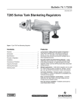
1
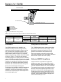
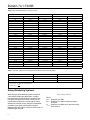
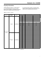
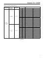
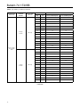
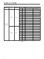
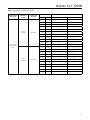
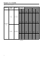
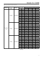
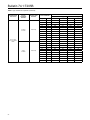
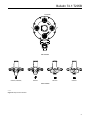
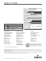
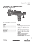
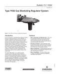
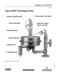
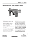
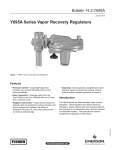
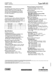
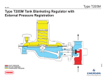
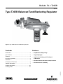
Bulletin 74.1:T205B
April 2014
Type T205B Balanced Tank Blanketing Regulator
Figure 1. Type T205B Balanced Tank Blanketing Regulator
Contents
Features
Introduction .................................................................. 2
• Fully Balanced Plug Design
Specifications .............................................................. 2
• Large Diaphragm
Features ..................................................................... 3
Principle of Operation ................................................. 3
• Low-Pressure Setting and Fast Speed
of Response
Installation .................................................................. 4
• Accurate Control and Small Lockup Pressure
Overpressure Protection.............................................. 4
Capacity Information ................................................... 7
• Sour Gas Service Capability
Ordering Information ................................................. 23
D103749X012
Ordering Guide ......................................................... 23
www.fisherregulators.com
Bulletin 74.1:T205B
Specifications
This section lists the specifications of the Type T205B Balanced Tank Blanketing Regulator. Factory specification,
such as maximum temperature, maximum inlet and outlet pressures, spring range and seat or orifice size are
stamped on the nameplate fastened on the regulator at the factory.
Body Sizes and End Connection Styles
See Table 1
Flow Capacities
See Table 9
Maximum Allowable Inlet Pressure(1)
See Table 1
Material Temperature Capabilities(1)(2)
Elastomer Parts
Nitrile (NBR):
-40 to 180°F / -40 to 82°C
Fluorinated Ethylene Propylene (FEP):
-20 to 180°F/ -29 to 82°C
Fluorocarbon (FKM):
40 to 300°F / 4 to 149°C
Ethylene Propylene Diene (EPDM):
-20 to 225°F / -29 to 107°C
Perfluoroelastomer (FFKM):
0 to 300°F / -18 to 149°C
Body Materials
Gray cast iron: -20 to 300°F / -29 to 149°C
WCC Carbon steel: -20 to 300°F / -29 to 149°C
CF8M/CF3M Stainless steel:
-40 to 300°F / -40 to 149°C
Maximum Operating Inlet Pressure(1)
Gray cast iron: 150 psig / 10.3 bar
WCC Carbon steel or CF8M/CF3M Stainless
steel: 200 psig / 13.8 bar
Maximum Outlet (Casing) Pressure(1)
Gray cast iron: 35 psig / 2.4 bar
WCC Carbon steel or CF8M/CF3M Stainless
steel: 75 psig / 5.2 bar
Maximum Emergency Outlet Pressure to Avoid
Internal Parts Damage(1)
With Nitrile (NBR) or Fluorocarbon (FKM)
diaphragm: 35 psig / 2.4 bar
With Fluorinated Ethylene Propylene (FEP)
diaphragm: 10 psig / 0.69 bar
Outlet (Control) Pressure Range(1)
See Table 2
Shutoff Classification per ANSI/FCI 70-3-2004
Class VI (Soft Seat)
Pressure Registration
External
Orifice Size
3/8 inch / 9.5 mm
Flow and Sizing Coefficients
See Table 4
Cv Coefficients
See Table 8
Body and Casing Materials
Gray cast iron, WCC Carbon steel and
CF8M/CF3M Stainless steel(3)
Trim Materials
See Table 3
Spring Case Vent Connection
1/4 NPT
Diaphragm Case Control Line Connection
1/2 NPT
Approximate Weight
17.7 pounds / 8 kg
1. The pressure/temperature limits in this Bulletin or any applicable standard limitation should not be exceeded.
2. See Table 3 for operating temperature ranges for available trim combinations.
3. Pipe nipples and flanges are 316 Stainless steel for flanged body assemblies.
Introduction
Tank blanketing is the process of covering the surface
of a liquid stored in a vessel with a gas, usually
nitrogen and of maintaining a slightly positive pressure
in an enclosed storage tank. Tank blanketing prevents
a stored liquid from vaporizing into the atmosphere,
reduces liquid combustibility and prevents oxidation
or contamination of the liquid by reducing its exposure
to air. This process is used in various products, such
as adhesives, pharmaceuticals, pesticides, fertilizers,
fuels, inks and food additives.
2
Type T205B balanced tank blanketing regulator
(Figure 1) is a direct-operated regulator with fully
balanced plug design to reduce inlet pressure
sensitivity and with a large diaphragm to accurately
control tank pressure at low pressure settings on tank
blanketing systems. It uses a control line to sense the
pressure in an enclosed storage tank. Type T205B
maintains a slightly positive pressure and thereby
reduces the possibility of tank wall collapse during
pump out operation.
Bulletin 74.1:T205B
Balanced trim
assembly
Lever
Pusher post
INLET PRESSURE
OUTLET PRESSURE
ATMOSPHERIC PRESSURE
MXXXX
Orifice
Pressure
registration
Diaphragm
Valve disk
Type Y602-1 Vent
Control Spring
INLET PRESSURE
OUTLET PRESSURE
ATMOSPHERIC PRESSURE
LOADING PRESSURE
Type T205B
Fully Balanced Plug Design — Eliminates setpoint
changes caused by varying inlet pressure. This design
provides smooth opening of the plug for stable flow
and greater regulating flow capacity.
Principle of Operation
November 2012
Features
Type T205B Tank Blanketing Regulator
Figure 2. Type T205B Operational Schematic
Large Diaphragm — Highly sensitive to changes in
tank pressure. Available in various materials to suit
different applications.
Refer to Figure 2. Type T205B tank blanketing
regulator controls the vapor space pressure over a
stored liquid. When liquid is pumped out of the tank or
vapors in the tank condense, the pressure in the tank
decreases. Tank pressure is sensed by the actuator
diaphragm. Spring force pushes the pusher post
assembly, the valve disk moves away from the orifice,
allowing the blanketing gas flow to increase.
Low-Pressure Setting and Fast Speed of
Response — Applicable for low pressure setting as
low as 1 inch water column / 2.5 mbar. Type T205B
reacts quickly in changing tank vapor pressure due to
direct-operated construction.
When pressure in the tank increases, the actuator
diaphragm is pushed. Through the action of the
pusher post assembly, lever and valve stem, the valve
disk moves closer to the orifice reducing blanketing
gas flow.
Accurate Control and Small Lockup Pressure —
Type T205B has a large effective diaphragm area that
detects small pressure change and provides accurate
control at low pressure setting. Type T205B is a lever
style regulator; this regulator style increases force
for lockup, thus, shut off can be attained with small
lockup pressure.
The regulator plug is balanced (inlet pressure
creates equal upward and downward forces on these
components), therefore, the outlet (control) pressure of
the unit is not affected by inlet pressure variation.
Sour Gas Service Capability — Available construction
to meet NACE MR0175-2002.
3
Bulletin 74.1:T205B
HORIZONTAL PIPELINE
VENT POINTED DOWN
DOWNSTREAM CONTROL LINE
INLET PRESSURE
OUTLET PRESSURE
ATMOSPHERIC PRESSURE
LOADING PRESSURE
Figure 3. Type T205B Actuator Casing Drainage
Table 1. Body Sizes, End Connection Styles and Maximum Allowable Inlet Pressures
Inch
Body Size
3/4 or 1
DN
20 or 25
BODY MATERIAL
End Connection
styles(1)
Maximum ALLOWABLE inlet pressure
psig
bar
Gray cast iron
NPT
150
10.3
WCC Carbon steel
CF8M/CF3M
Stainless steel(2)
NPT, CL150 RF,
CL300 RF or
PN 16/25/40 RF
200
13.8
1. All flanges are welded. Weld-on flange dimension is 14 inches / 356 mm face-to-face.
2. Pipe nipples and flanges are 316 Stainless steel for flanged body assemblies.
Installation
Overpressure Protection
Type T205B regulator may be installed in any
orientation as long as the flow through the body
matches the direction indicated by the arrow on the
body. To achieve the published capacities at low
setpoint, the spring case barrel should be installed
pointed down as shown in Figure 2. For complete
actuator casing drainage, regulator should be installed
as shown in Figure 3. To keep the vent assembly
from being plugged or the spring case from collecting
moisture, corrosive chemicals or other foreign material,
point the vent down or otherwise protect it. If an indoor
installation is required and if hazardous gas service
is used, the vent should be piped outside. External
dimensions and connections are shown in Figure 5.
Type T205B regulator has an outlet pressure ratings
that are lower than its inlet pressure ratings. Install
downstream overpressure protection if the inlet
pressure can exceed the outlet pressure rating.
Emerson Process Management Regulator
Technologies, Inc. provides an instruction manual with
every regulator shipped. Refer to this for complete
installation, operation and maintenance instructions.
Included is a complete listing of individual parts and
recommended spare parts.
4
Refer to the Capacity Information section and the
relief sizing coefficients in the Specification sections to
determine the required relief valve capacity.
Universal NACE Compliance
Optional materials are available for applications
handling sour gases. These constructions comply
with the recommendations of National Association of
Corrosion Engineers (NACE) sour service standards.
The manufacturing processes and materials used by
Emerson assure that all products specified for sour
gas service comply with the chemical, physical and
metallurgical requirements of NACE MR0175-2002.
Customers have the responsibility to specify correct
materials. Environmental limitations may apply and
shall be determined by the user.
Bulletin 74.1:T205B
Table 2. Outlet (Control) Pressure Ranges and Spring Information
Outlet (Control) Pressure Range
Inch w.c.
mbar
1.0 to 2.5(1)(2)
2.5 to 7.0(2)
7.0 to 16.0
0.5 to 1.2 psig
1.2 to 2.5 psig
2.5 to 4.5 psig
4.5 to 7 psig
2.5 to 6.2(1)(2)
6.2 to 17(2)
17 to 40
34 to 83
83 to 172
0.17 to 0.31 bar
0.31 to 0.48 bar
Spring Wire Diameter
Spring Color
Orange
Red
Unpainted
Yellow
Green
Light Blue
Black
Spring Free Length
Inch
mm
Inch
mm
0.072
0.085
0.105
0.114
0.156
0.187
0.218
1.8
2.2
2.7
2.9
4.0
4.8
5.5
3.25
3.63
3.75
4.31
4.06
3.94
3.98
82.6
92.2
95.2
109
103
100
101
1. Do not use Fluorocarbon (FKM) diaphragm with this spring at diaphragm temperatures lower than 60°F / 16°C.
2. To achieve the published outlet pressure range the spring case must be installed pointing down.
Table 3. Available Construction and Trim Materials
Available construction materials
Body and
Casing
Guide
Insert
Gray cast iron,
WCC Carbon
Steel,
or CF8M/
CF3M
Stainless
steel(1)
Diaphragm
Head
316
Stainless
steel
304
Stainless
steel
Lever
Assembly
and Bias
Spring
302
Stainless
steel
Available trim options
Stem
Trim Option
Diaphragm Material
Code
Disk and O-ring
Material
Operating Temperature
Ranges
Standard
Fluorinated Ethylene
Propylene (FEP)
Nitrile (NBR)
-20 to 180°F /
-29 to 82°C
NN
Nitrile (NBR)
Nitrile (NBR)
-40 to 180°F /
-40 to 82°C
VV
Fluorocarbon (FKM)
Fluorocarbon (FKM)
40 to 300°F /
4 to 149°C
TV
Fluorinated Ethylene
Propylene (FEP)
Fluorocarbon (FKM)
40 to 180°F /
4 to 82°C
TK
Fluorinated Ethylene
Propylene (FEP)
Perfluoroelastomer
(FFKM)
0 to 180°F /
-18 to 82°C
TE
Fluorinated Ethylene
Propylene (FEP)
Ethylene Propylene
Diene (EPDM)
-20 to 180°F /
-29 to 82°C
Nitronic 60
®
1. Pipe nipples and flanges are 316 Stainless steel for flanged body assemblies.
Nitronic® is a registered trademark of AK Steel Corporation.
Table 4. Type T205B Flow and Sizing Coefficients
ORIFICE SIZE
REGULATING
WIDE-OPEN
Inch
mm
Cg
Cv
C1
Cg
Cv
C1
3/8
9.5
98
2.8
34.6
101
2.9
34.6
Table 5. Flow Rate Conversion
Multiply Maximum Pump Rate In
BY
U.S. GPM
8.021
U.S. GPH
0.1337
Barrels/hour
5.615
Barrels/day
0.2340
TO OBTAIN
SCFH air required(1)
1. To convert to Nm3/h multiply SCFH by 0.0268.
5
Bulletin 74.1:T205B
Table 6. Flow Rate Required due to Thermal Cooling
VESSEL CAPACITY
Barrels
Gallons
AIR FLOW RATE REQUIRED(1)
Liters
SCFH
Nm3/h
1.6
60
2500
9500
60
100
4200
16,000
100
2.7
500
21,000
79,500
500
13.4
1000
42,000
159,000
1000
26.8
2000
84,000
318,000
2000
53.6
3000
126,000
477,000
3000
80.4
4000
168,000
636,000
4000
107
5000
210,000
795,000
5000
134
10,000
420,000
1,590,000
10,000
268
15,000
630,000
2,385,000
15,000
402
20,000
840,000
3,180,000
20,000
536
25,000
1,050,000
3,975,000
24,000
643
30,000
1,260,000
4,769,000
28,000
750
35,000
1,470,000
5,564,000
31,000
831
40,000
1,680,000
6,359,000
34,000
911
45,000
1,890,000
7,154,000
37,000
992
50,000
2,100,000
7,949,999
40,000
1072
60,000
2,520,000
9,539,000
44,000
1179
70,000
2,940,000
11,129,000
48,000
1286
80,000
3,360,000
12,718,000
52,000
1394
90,000
3,780,000
14,308,000
56,000
1501
100,000
4,200,000
15,898,000
60,000
1608
120,000
5,040,000
19,078,000
68,000
1822
140,000
5,880,000
22,257,000
75,000
2010
160,000
6,720,000
25,347,000
82,000
2198
180,000
7,560,000
28,616,000
90,000
2412
1. Flash point is below 100°F / 38°C or normal boiling point is below 300°F / 149°C.
Table 7. Correction Factors (For Converting Air Flow Rates to Other Gas Flow Rates)(1)
Blanket gas
Specific gravity
Correction factor
Natural Gas
0.60
1.291
Nitrogen
0.97
1.015
Dry CO2
1.52
0.811
1. For gases of other specific gravities, use equation below.
Correction Factor =
1.00
SG
Sizing Blanketing Systems
When sizing a gas blanketing regulator system for
a low-pressure blanketing application, consider
the replacement of blanketing gas required for the
liquid loss during pump out of the vessel plus the
condensation/contraction of vessel vapors during
atmospheric thermal cooling. Using the established
procedures from American Petroleum Institute
Standard 2000 (API 2000), determine the flow rate of
blanketing gas required.
6
Qtotal = Qpump + Qthermal
Where,
Qtotal: Required Flow Rate.
Qpump: Required Flow Rate to replace pumped
out liquid.
Qthermal: Required Flow Rate due to thermal cooling.
(See Table 6)
Bulletin 74.1:T205B
Capacity Information
Capacity tables are based on 1.0 specific gravity
air. If other blanketing gas is used, convert the
tabular values as follows. For blanketing (pad) gases
other than air, multiply the given air flow rate by
the correction factors in Table 6. For gases of other
specific gravities, divide the given air flow rate by the
square root of the appropriate specific gravity.
Table 8. Type T205B Cv Coefficient
Spring Range
and Color
Outlet
Pressure
Setting
1 inch w.c. /
2.5 mbar
Offset from
Setpoint
-1 to +2 inches w.c. /
-2.5 to +5.0 mbar
1.0 to 2.5 inches w.c. /
2.5 to 6.2 mbar
Orange
2.5 inches w.c. /
6.2 mbar
-1 to +2 inches w.c. /
-2.5 to +5.0 mbar
Cv coefficient
Inlet Pressure
psig
bar
3/4 Inch / DN 20 Body Size
1 Inch / DN 25 Body Size
1
0.07
1.9
2.7
2
0.14
2.2
2.7
4
0.28
2.3
2.6
6
0.41
2.3
2.8
8
0.55
2.3
2.8
10
0.69
2.4
2.8
15
1.0
2.4
2.8
20
1.4
2.4
2.7
40
2.8
2.5
2.7
60
4.1
2.5
2.6
80
5.5
2.4
2.2
100
6.9
1.8
1.6
125
8.6
1.3
1.3
150
10.3
1.0
1.2
175
12.1
0.9
1.1
200
13.8
0.8
0.8
1
0.07
2.1
2.6
2
0.14
2.3
2.7
4
0.28
2.5
2.6
6
0.41
2.5
2.6
8
0.55
2.5
2.7
10
0.69
2.5
2.8
15
1.0
2.5
2.7
20
1.4
2.5
2.7
40
2.8
2.6
2.6
60
4.1
2.5
2.6
80
5.5
2.5
2.6
100
6.9
2.5
1.9
125
8.6
1.5
1.4
150
10.3
1.0
1.2
175
12.1
0.9
1.1
200
13.8
0.8
0.9
- continued -
7
Bulletin 74.1:T205B
Table 8. Type T205B Cv Coefficient (continued)
Spring Range
and Color
Outlet
Pressure
Setting
2.5 inches w.c. /
6.2 mbar
2.5 to 7.0 inches w.c. /
6.2 to 17 mbar
Red
4 inches w.c. /
10 mbar
7 inches w.c. /
17 mbar
Offset from
Setpoint
-1 to +2 inches w.c. /
-2.5 to +5.0 mbar
-1 to +2 inches w.c. /
-2.5 to +5.0 mbar
-2 to +2 inches w.c. /
-5 to +5.0 mbar
Inlet Pressure
psig
bar
3/4 Inch / DN 20 Body Size
1 Inch / DN 25 Body Size
1
0.07
1.8
1.8
2
0.14
1.9
1.8
4
0.28
2.0
1.9
6
0.41
2.1
1.9
8
0.55
2.1
1.9
10
0.69
2.1
1.9
15
1.0
2.3
2.0
20
1.4
2.3
2.0
40
2.8
2.5
2.5
60
4.1
2.5
2.6
80
5.5
2.5
2.6
100
6.9
2.5
2.6
125
8.6
1.7
1.7
150
10.3
1.3
1.3
175
12.1
1.1
1.1
200
13.8
1.0
0.9
1
0.07
1.4
1.6
2
0.14
1.5
1.5
4
0.28
1.6
1.5
6
0.41
1.6
1.6
8
0.55
1.8
1.5
10
0.69
1.9
1.6
15
1.0
2.0
1.6
20
1.4
2.1
1.8
40
2.8
2.4
2.3
60
4.1
2.5
2.6
80
5.5
2.5
2.6
100
6.9
2.5
2.6
2.0
125
8.6
2.5
150
10.3
1.4
1.4
175
12.1
1.2
1.0
200
13.8
1.0
0.9
1
0.07
2.1
2.1
2
0.14
2.2
2.1
4
0.28
2.1
2.0
6
0.41
2.2
2.1
8
0.55
2.1
2.2
10
0.69
2.2
2.2
15
1.0
2.4
2.2
20
1.4
2.2
2.3
40
2.8
2.5
2.5
60
4.1
2.5
2.5
80
5.5
2.5
2.6
100
6.9
2.5
2.6
125
8.6
2.5
2.6
150
10.3
1.7
1.9
175
12.1
1.4
1.5
200
13.8
1.1
1.3
- continued 8
Cv coefficient
Bulletin 74.1:T205B
Table 8. Type T205B Cv Coefficient (continued)
Spring Range
and Color
Outlet
Pressure
Setting
11 inches w.c. /
27 mbar
Offset from
Setpoint
20% droop
7.0 to
16.0 inches w.c. /
17 to 40 mbar
Unpainted
15 inches w.c. /
37 mbar
20% droop
Cv coefficient
Inlet Pressure
psig
bar
3/4 Inch / DN 20 Body Size
1 Inch / DN 25 Body Size
1
0.07
1.5
1.9
2
0.14
1.6
1.6
4
0.28
1.5
1.6
6
0.41
1.6
1.7
8
0.55
1.7
1.6
10
0.69
1.7
1.7
15
1.0
1.8
1.7
20
1.4
1.8
1.7
40
2.8
2.1
1.9
60
4.1
2.3
2.2
80
5.5
2.4
2.3
100
6.9
2.4
2.4
125
8.6
2.5
2.6
150
10.3
2.4
2.4
175
12.1
2.5
2.1
200
13.8
1.9
1.9
2
0.14
1.9
1.9
4
0.28
1.7
1.8
6
0.41
1.8
1.9
8
0.55
1.9
1.8
10
0.69
1.8
1.9
15
1.0
1.9
1.9
20
1.4
2.0
1.9
40
2.8
2.2
2.1
60
4.1
2.3
2.3
80
5.5
2.4
2.4
100
6.9
2.4
2.5
125
8.6
2.5
2.5
150
10.3
2.5
2.4
175
12.1
2.5
2.5
200
13.8
2.5
2.5
- continued -
9
Bulletin 74.1:T205B
Table 8. Type T205B Cv Coefficient (continued)
Spring Range
and Color
Outlet
Pressure
Setting
0.5 psig /
34 mbar
Offset from
Setpoint
20% droop
0.5 to 1.2 psig /
34 to 83 mbar
Yellow
1.2 psig /
83 mbar
20% droop
Inlet Pressure
psig
bar
3/4 Inch / DN 20 Body Size
1 Inch / DN 25 Body Size
2
0.14
1.5
1.6
4
0.28
1.5
1.6
6
0.41
1.5
1.5
8
0.55
1.5
1.5
10
0.69
1.5
1.4
15
1.0
1.5
1.5
20
1.4
1.5
1.5
40
2.8
1.7
1.5
60
4.1
1.9
1.8
80
5.5
2.1
2.0
100
6.9
2.3
2.2
125
8.6
2.3
2.3
150
10.3
2.4
2.3
175
12.1
2.4
2.4
200
13.8
2.4
2.4
2
0.14
2.0
2.2
4
0.28
1.8
1.9
6
0.41
2.0
2.0
8
0.55
1.9
2.1
10
0.69
1.9
2.0
15
1.0
1.9
2.0
20
1.4
2.0
2.0
40
2.8
2.2
2.1
60
4.1
2.2
2.2
80
5.5
2.2
2.2
100
6.9
2.3
2.3
125
8.6
2.4
2.4
150
10.3
2.3
2.0
175
12.1
2.4
2.2
200
13.8
2.4
2.2
- continued -
10
Cv coefficient
Bulletin 74.1:T205B
Table 8. Type T205B Cv Coefficient (continued)
Spring Range
and Color
Outlet
Pressure
Setting
1.2 psig / 83 mbar
Offset from
Setpoint
20% droop
1.2 psig to 2.5 psig /
83 to 172 mbar
Green
2.5 psig / 172 mbar
20% droop
Inlet Pressure
Cv coefficient
psig
bar
3/4 Inch / DN 20 Body Size
1 Inch / DN 25 Body Size
2
0.14
1.4
1.5
4
0.28
1.2
1.3
6
0.41
1.2
1.2
8
0.55
1.2
1.2
10
0.69
1.2
1.1
15
1.0
1.1
1.1
20
1.4
1.2
1.1
40
2.8
1.1
1.1
60
4.1
1.1
1.1
80
5.5
1.2
1.1
100
6.9
1.2
1.2
125
8.6
1.3
1.2
150
10.3
1.4
1.4
175
12.1
1.4
1.3
200
13.8
1.4
1.2
4
0.28
1.9
1.9
6
0.41
1.5
1.8
8
0.55
1.6
1.7
10
0.69
1.8
1.7
15
1.0
1.7
1.8
20
1.4
1.7
1.8
40
2.8
1.8
1.7
60
4.1
1.8
1.8
80
5.5
1.9
1.8
100
6.9
1.9
1.8
125
8.6
1.9
1.9
150
10.3
2.0
1.6
175
12.1
1.9
1.8
200
13.8
2.0
1.9
- continued -
11
Bulletin 74.1:T205B
Table 8. Type T205B Cv Coefficient (continued)
Spring Range
and Color
Outlet
Pressure
Setting
2.5 psig /
0.17 bar
Offset from
Setpoint
20% droop
2.5 to 4.5 psig /
0.17 to 0.31 bar
Light Blue
4.5 psig /
0.31 bar
20% droop
Inlet Pressure
psig
bar
3/4 Inch / DN 20 Body Size
1 Inch / DN 25 Body Size
4
0.28
1.4
1.4
6
0.41
1.2
1.2
8
0.55
1.1
1.2
10
0.69
1.2
1.2
15
1.0
1.1
1.1
20
1.4
1.1
1.2
40
2.8
1.1
1.1
60
4.1
1.1
1.0
80
5.5
1.1
1.1
100
6.9
1.1
1.1
125
8.6
1.1
1.1
150
10.3
1.1
1.0
175
12.1
1.2
1.0
200
13.8
1.2
1.0
8
0.55
1.7
1.7
10
0.69
1.5
1.7
15
1.0
1.6
1.6
20
1.4
1.6
1.6
40
2.8
1.7
1.6
60
4.1
1.7
1.5
80
5.5
1.7
1.6
100
6.9
1.7
1.6
125
8.6
1.7
1.6
150
10.3
1.7
1.4
175
12.1
1.7
1.5
200
13.8
1.7
1.5
- continued -
12
Cv coefficient
Bulletin 74.1:T205B
Table 8. Type T205B Cv Coefficient (continued)
Spring Range
and Color
Outlet
Pressure
Setting
4.5 psig /
0.31 bar
Offset from
Setpoint
20% droop
4.5 to 7 psig /
0.31 to 0.48 bar
Black
7 psig /
0.48 bar
20% droop
Cv coefficient
Inlet Pressure
psig
bar
3/4 Inch / DN 20 Body Size
1 Inch / DN 25 Body Size
10
0.69
1.1
1.2
15
1.0
1.1
1.1
20
1.4
1.1
1.1
40
2.8
1.1
1.1
60
4.1
1.1
1.0
80
5.5
1.1
1.1
100
6.9
1.1
1.1
125
8.6
1.1
1.1
150
10.3
1.1
0.9
175
12.1
1.1
1.1
200
13.8
1.0
1.0
10
0.69
1.7
1.7
15
1.0
1.6
1.6
20
1.4
1.5
1.5
40
2.8
1.5
1.5
60
4.1
1.5
1.5
80
5.5
1.5
1.4
100
6.9
1.5
1.5
125
8.6
1.5
1.5
150
10.3
1.5
1.3
175
12.1
1.5
1.4
200
13.8
1.5
1.3
13
Bulletin 74.1:T205B
Table 9. Type T205B Flow Capacities
Spring Range
and Color
Outlet
Pressure
Setting
1 inch w.c. /
2.5 mbar
Offset from
Setpoint
-1 to +2 inches w.c. /
-2.5 to +5.0 mbar
1.0 to 2.5 inches w.c. /
2.5 to 6.2 mbar
Orange
2.5 inches w.c. /
6.2 mbar
-1 to +2 inches w.c. /
-2.5 to +5.0 mbar
Inlet Pressure
3/4 Inch / DN 20 Body Size
1 Inch / DN 25 Body Size
psig
bar
SCFH
Nm3h
SCFH
Nm3h
1
0.07
434
11.6
603
16.2
2
0.14
708
19.0
852
22.8
4
0.28
1056
28.3
1204
32.3
6
0.41
1328
35.6
1595
42.7
8
0.55
1563
41.9
1876
50.3
10
0.69
1840
49.3
2094
56.1
15
1.0
2304
61.7
2698
72.3
20
1.4
2729
73.1
3149
84.4
40
2.8
4678
125
5002
134.1
60
4.1
6353
170
6748
181
80
5.5
7957
213
8614
231
100
6.9
9801
263
10,473
281
125
8.6
9955
267
9463
254
150
10.3
8852
237
7015
188
175
12.1
8554
229
7675
206
200
13.8
9118
244
6628
178
1
0.07
455
12.2
563
15.1
2
0.14
711
19.1
838
22.5
4
0.28
1122
30.1
1201
32.2
6
0.41
1429
38.3
1485
39.8
8
0.55
1681
45.1
1820
48.8
10
0.69
1886
50.5
2086
55.9
15
1.0
2418
64.8
2638
70.7
20
1.4
2834
76.0
3081
82.6
40
2.8
4838
130
4958
133
60
4.1
6456
173
6729
180
80
5.5
8271
222
8531
229
100
6.9
10,044
269
10,396
279
125
8.6
11,997
322
12,662
339
150
10.3
9273
249
8001
214
175
12.1
9248
248
8034
215
200
13.8
9010
241
7029
188
- continued -
14
Capacities in SCFH / Nm3h of Air
Bulletin 74.1:T205B
Table 9. Type T205B Flow Capacities (continued)
Spring Range
and Color
Outlet
Pressure
Setting
2.5 inches w.c. /
6.2 mbar
2.5 to 7.0 inches w.c. /
6.2 to 17 mbar
Red
4 inches w.c. /
10 mbar
7 inches w.c. /
17 mbar
Offset from
Setpoint
-1 to +2 inches w.c. /
-2.5 to +5.0 mbar
-1 to +2 inches w.c. /
-2.5 to +5.0 mbar
-2 to +2 inches w.c. /
-5 to +5.0 mbar
Inlet Pressure
Capacities in SCFH / Nm3h of Air
3/4 Inch / DN 20 Body Size
1 Inch / DN 25 Body Size
psig
bar
SCFH
Nm3h
SCFH
Nm3h
1
0.07
391
10.5
402
10.8
2
0.14
594
15.9
580
15.5
4
0.28
923
24.7
850
22.8
6
0.41
1216
32.6
1058
28.4
8
0.55
1411
37.8
1249
33.5
10
0.69
1563
41.9
1463
39.2
15
1.0
2194
58.8
1922
51.5
20
1.4
2650
71.0
2340
62.7
40
2.8
4758
128
4730
127
60
4.1
6421
172
6676
179
80
5.5
8180
219
8534
229
100
6.9
10,000
268
10,340
277
125
8.6
12,193
327
12,658
339
150
10.3
14,498
389
11,300
303
175
12.1
11,208
300
10,474
281
200
13.8
11,341
304
9858
264
1
0.07
298
8.0
340
9.1
2
0.14
470
12.6
472
12.6
4
0.28
735
19.7
686
18.4
6
0.41
904
24.2
878
23.5
8
0.55
1183
31.7
983
26.3
10
0.69
1396
37.4
1212
32.5
15
1.0
1913
51.3
1520
40.7
20
1.4
2416
64.7
2036
54.6
40
2.8
4505
121
4390
118
60
4.1
6388
171
6598
177
80
5.5
8191
220
8385
225
100
6.9
10,032
269
10,222
274
125
8.6
12,171
326
12,576
337
150
10.3
14,540
390
14,402
386
175
12.1
13,210
354
12,087
324
200
13.8
11,877
318
10,424
279
1
0.07
417
11.2
417
11.2
2
0.14
673
18.0
626
16.8
4
0.28
963
25.8
916
24.5
6
0.41
1219
32.7
1199
32.1
8
0.55
1410
37.8
1468
39.3
10
0.69
1676
44.9
1666
44.6
15
1.0
2276
61.0
2100
56.3
20
1.4
2571
68.9
2639
70.7
40
2.8
4625
124.0
4641
124
60
4.1
6302
169
6535
175
80
5.5
8179
219
8412
225
100
6.9
9897
265
10,225
274
125
8.6
12,129
325
12,497
335
150
10.3
14,390
386
14,165
380
175
12.1
16,671
447
16,734
448
200
13.8
13,907
373
19,101
512
- continued -
15
Bulletin 74.1:T205B
Table 9. Type T205B Flow Capacities (continued)
Spring Range
and Color
Outlet
Pressure
Setting
11 inches w.c. /
27 mbar
Offset from
Setpoint
20% droop
7.0 to
16.0 inches w.c. /
17 to 40 mbar
Unpainted
15 inches w.c. /
37 mbar
20% droop
Inlet Pressure
3/4 Inch / DN 20 Body Size
1 Inch / DN 25 Body Size
psig
bar
SCFH
Nm3h
SCFH
Nm3h
1
0.07
272
7.3
340
9.1
2
0.14
453
12.1
458
12.3
4
0.28
679
18.2
696
18.7
6
0.41
879
23.6
920
24.7
8
0.55
1087
29.1
1080
28.9
10
0.69
1258
33.7
1266
33.9
15
1.0
1673
44.8
1639
43.9
20
1.4
2054
55.0
1938
51.9
40
2.8
3868
104
3595
96.3
60
4.1
5801
156
5764
154
80
5.5
7695
206
7616
204
100
6.9
9559
256
9636
258
125
8.6
11,986
321
12,258
329
150
10.3
13,813
370
13,781
369
175
12.1
16,389
439
15,565
417
200
13.8
18,695
501
18,494
496
2
0.14
537
14.4
534
14.3
4
0.28
752
20.2
776
20.8
6
0.41
994
26.6
1028
27.6
8
0.55
1224
32.8
1157
31.0
10
0.69
1336
35.8
1391
37.3
15
1.0
1831
49.1
1770
47.4
20
1.4
2248
60.2
2205
59.1
40
2.8
4063
109
3846
103
60
4.1
5892
158
5865
157
80
5.5
7718
207
7699
206
100
6.9
9562
256
9738
261
125
8.6
11,899
319
12,035
323
150
10.3
13,895
372
13,352
358
175
12.1
15,977
428
16,046
430
200
13.8
18,568
498
18,554
497
- continued -
16
Capacities in SCFH / Nm3h of Air
Bulletin 74.1:T205B
Table 9. Type T205B Flow Capacities (continued)
Spring Range
and Color
Outlet
Pressure
Setting
0.5 psig /
34 mbar
Offset from
Setpoint
20% droop
0.5 to 1.2 psig /
34 to 83 mbar
Yellow
1.2 psig /
83 mbar
20% droop
Inlet Pressure
Capacities in SCFH / Nm3h of Air
3/4 Inch / DN 20 Body Size
1 Inch / DN 25 Body Size
psig
bar
SCFH
Nm3h
SCFH
Nm3h
2
0.14
412
11.0
449
12.0
4
0.28
660
17.7
674
18.1
6
0.41
834
22.4
844
22.6
8
0.55
1007
27.0
950
25.5
10
0.69
1148
30.8
1067
28.6
15
1.0
1474
39.5
1386
37.1
20
1.4
1773
47.5
1719
46.1
40
2.8
3208
86.0
2886
77.3
60
4.1
5005
134
4731
127
80
5.5
6967
187
6590
177
100
6.9
8906
239
8858
237
125
8.6
11,231
301
11,100
298
150
10.3
13,636
365
12,946
347
175
12.1
15,861
425
15,565
417
200
13.8
17,949
481
17,585
471
2
0.14
422
11.3
466
12.5
4
0.28
725
19.4
769
20.6
6
0.41
1030
27.6
1074
28.8
8
0.55
1207
32.3
1311
35.1
10
0.69
1388
37.2
1489
39.9
15
1.0
1779
47.7
1912
51.2
20
1.4
2321
62.2
2330
62.4
40
2.8
4052
109
3858
103
60
4.1
5536
148
5711
153
80
5.5
7322
196
7228
194
100
6.9
9006
241
9023
242
125
8.6
11,329
304
11,471
307
150
10.3
13,188
353
11,316
303
175
12.1
15,494
415
14,402
386
200
13.8
17,694
474
16,532
443
- continued -
17
Bulletin 74.1:T205B
Table 9. Type T205B Flow Capacities (continued)
Spring Range
and Color
Outlet
Pressure
Setting
1.2 psig / 83 mbar
Offset from
Setpoint
20% droop
1.2 psig to 2.5 psig /
83 to 172 mbar
Green
2.5 psig / 172 mbar
20% droop
Inlet Pressure
3/4 Inch / DN 20 Body Size
1 Inch / DN 25 Body Size
psig
bar
SCFH
Nm3h
SCFH
Nm3h
2
0.14
296
7.9
313
8.4
4
0.28
474
12.7
497
13.3
6
0.41
619
16.6
621
16.6
8
0.55
748
20.0
730
19.6
10
0.69
893
23.9
831
22.3
15
1.0
1070
28.7
1073
28.8
20
1.4
1318
35.3
1266
33.9
40
2.8
2063
55.3
2004
53.7
60
4.1
2879
77.2
2864
76.8
80
5.5
3791
102
3526
94.5
100
6.9
4683
126
4843
130
125
8.6
6054
162
5956
160
150
10.3
7699
206
7844
210
175
12.1
9024
242
8195
220
200
13.8
10,650
285
8982
241
4
0.28
560
15.0
581
15.6
6
0.41
698
18.7
834
22.4
8
0.55
923
24.7
1023
27.4
10
0.69
1246
33.4
1192
31.9
15
1.0
1552
41.6
1638
43.9
20
1.4
1908
51.1
1996
53.5
40
2.8
3337
89.4
3217
86.2
60
4.1
4676
125
4564
122
80
5.5
6060
162
5922
159
100
6.9
7405
199
7209
193
125
8.6
9223
247
8995
241
150
10.3
11,164
299
9333
250
175
12.1
12,347
331
11,432
306
200
13.8
15,029
403
13,640
366
- continued -
18
Capacities in SCFH / Nm3h of Air
Bulletin 74.1:T205B
Table 9. Type T205B Flow Capacities (continued)
Spring RangE
and Color
Outlet
Pressure
Setting
2.5 psig /
0.17 bar
Offset from
Setpoint
20% droop
2.5 to 4.5 psig /
0.17 to 0.31 bar
Light Blue
4.5 psig /
0.31 bar
20% droop
Inlet Pressure
Capacities in SCFH / Nm3h of Air
3/4 Inch / DN 20 Body Size
1 Inch / DN 25 Body Size
psig
bar
SCFH
Nm3h
SCFH
Nm3h
4
0.28
407
10.9
418
11.2
6
0.41
555
14.9
557
14.9
8
0.55
645
17.3
679
18.2
10
0.69
800
21.4
804
21.5
15
1.0
1009
27.0
1039
27.8
20
1.4
1220
32.7
1291
34.6
40
2.8
2064
55.3
1964
52.6
60
4.1
2876
77.1
2674
71.7
80
5.5
3683
98.7
3545
95.0
100
6.9
4525
121
4319
116
125
8.6
5485
147
5293
142
150
10.3
6237
167
5739
154
175
12.1
7547
202
6810
183
200
13.8
8673
232
7427
199
8
0.55
823
22.1
854
22.9
10
0.69
949
25.4
1075
28.8
15
1.0
1412
37.8
1411
37.8
20
1.4
1723
46.2
1729
46.3
40
2.8
3067
82.2
2880
77.2
60
4.1
4252
114
3836
103
80
5.5
5513
148
5200
139
100
6.9
6682
179
6236
167
125
8.6
8249
221
7916
212
150
10.3
9787
262
8032
215
175
12.1
11,084
297
9703
260
200
13.8
12,748
342
11,264
302
- continued -
19
Bulletin 74.1:T205B
Table 9. Type T205B Flow Capacities (continued)
Spring Range
and Color
Outlet
Pressure
Setting
4.5 psig /
0.31 bar
Offset from
Setpoint
20% droop
4.5 to 7 psig /
0.31 to 0.48 bar
Black
7 psig /
0.48 bar
20
20% droop
Inlet Pressure
Capacities in SCFH / Nm3h of Air
3/4 Inch / DN 20 Body Size
1 Inch / DN 25 Body Size
psig
bar
SCFH
Nm3h
SCFH
Nm3h
10
0.69
706
18.9
741
19.9
15
1.0
978
26.2
1003
26.9
20
1.4
1161
31.1
1237
33.2
40
2.8
1993
53.4
2012
53.9
60
4.1
2776
74.4
2661
71.3
80
5.5
3477
93.2
3426
91.8
100
6.9
4265
114
4163
112
125
8.6
5233
140
5161
138
150
10.3
6206
166
5200
139
175
12.1
7053
189
7007
188
200
13.8
7705
207
7620
204
10
0.69
810
21.7
821
22.0
15
1.0
1289
34.5
1282
34.4
20
1.4
1576
42.2
1596
42.8
40
2.8
2836
76.0
2737
73.4
60
4.1
3870
104
3734
100
80
5.5
4923
132
4716
126
100
6.9
6001
161
5737
154
125
8.6
7307
196
7058
189
150
10.3
8380
225
7324
196
175
12.1
9560
256
9388
252
200
13.8
11,332
304
9637
258
POSITION 1 (STANDARD)
Bulletin 74.1:T205B
POSITION 2
POSITION 3
POSITION 4
BODY POSITION
A (STANDARD)
B
D
C
VENT POSITION
Vent position
POSITION 1 (STANDARD)
POSITION 2
POSITION 3
POSITION 4
BODY POSITION
Body position
A (STANDARD)
ERSA00746
Figure 4. Body and Vent Position
B
D
C
21
Bulletin 74.1:T205B
8.38 / 212.9
1/4 NPT VENT
NPT
5.58 /
141.6
FLANGED
4.12 /
104.6
2.25 /
57.2
1/2 NPT CONTROL
LINE CONNECTION
6.18 / 157
1.59 /
40.4
10.37 / 263.4
TYPE T205B WITH NPT END CONNECTION
14 /
355.6
8.07 / 205
MAXIMUM
7.19 /
182.6
TYPE T205B WITH
FLANGED END CONNECTION
SPRING ADJUSTMENT ASSEMBLY OPTION
ERSA02735
Figure 5. Dimensions
22
INCH / mm
Bulletin 74.1:T205B
Ordering Information
When ordering, complete the ordering guide on
this page. Refer to the Specifications section on
page 2. Review the description to the right of each
specification and the information in each referenced
table or figure. Specify your choice whenever a
selection is offered.
Ordering Guide
Body Size (Select One)
Adjusting Screw (Select One)
3/4 inch / DN 20***
1 inch / DN 25***
Internal Flat Circular (standard)***
E
xternal Square Head (Available for Green,
Light blue and Black springs only. Steel closing
cap is automatically supplied in this option)***
Body Material and End Connection Style (Select One)
Gray Cast Iron
NPT***
Closing Cap Material (Select One)
WCC Carbon Steel
NPT***
CL150 RF***
CL300 RF***
PN 16/25/40 RF*** specify rating _________
Plastic (standard) (not available for Green,
Light blue and Black springs)***
Steel (standard for Green, Light blue and
Black springs)***
Stainless steel***
CF8M/CF3M Stainless steel(1)
NPT***
CL150 RF***
CL300 RF***
PN 16/25/40 RF*** specify rating _________
Body Position (See Figure 4, Select One)
Outlet (Control) Pressure Range (Select One)
Spring Case Orientation/Vent Type (Select One)
1 to 2.5 inches w.c. / 2.5 to 6.2 mbar, Orange***
2.5 to 7 inches w.c. / 6.2 to 17 mbar, Red***
7 to 16 inches w.c. / 17 to 40 mbar, Unpainted***
0.5 to 1.2 psig / 34 to 83 mbar, Yellow***
1.2 to 2.5 psig / 83 to 172 mbar, Green***
2.5 to 4.5 psig / 0.17 to 0.31 bar, Light Blue***
4.5 to 7 psig / 0.31 to 0.48 bar, Black
Trim Material (See Table 3, Select One)
Standard***
NN***
VV***
TV***
TK***
TE***
Position 1 (standard)***
Position 2***
Position 3***
Position 4***
Spring Case Side (Type Y602-12) (standard)***
Spring Case Down (Type Y602-1)***
Spring Case Up (Type Y602-11)***
Vent Position (See Figure 4, Select One)
Position A (standard)***
Position B***
Position C***
Position D***
316 Stainless steel Trim Parts (Select One)
Yes
No
Replacement Parts Kit (Optional)
Yes, send one replacement parts kit to match
this order.
1. Pipe nipples and flanges are 316 Stainless steel for flanged body assemblies.
23
Bulletin 74.1:T205B
Specification Worksheet
Application (Please designate units):
Specifi c Use Line Size Fluid Type and Specifi c Gravity Fluid Temperature
Does the Application Require Overpressure Protection? Yes
No If yes, which is preferred: Relief Valve Monitor Regulator Shutoff Device
Is overpressure protection equipment selection assistance
desired? Pressure:
Maximum Inlet Pressure
Minimum Inlet Pressure
Differential Pressure
Set Pressure
Maximum Flow (Qmax)
Regulators Quick Order Guide
***
**
*
Readily Available for Shipment
Allow Additional Time for Shipment
Special Order, Constructed from Non-Stocked Parts. Consult your local Sales Offi ce for Availability.
Performance Required:
Accuracy Requirements?
Less than or Equal to:
5%
10%
20%
Wide Open
Other Requirements:
Availability of the product being ordered is determined by the component with the
longest shipping time for the requested construction.
Industrial Regulators
Natural Gas Technologies
TESCOM
Emerson Process Management
Regulator Technologies, Inc.
Emerson Process Management
Regulator Technologies, Inc.
Emerson Process Management
Tescom Corporation
USA - Headquarters
McKinney, Texas 75070 USA
Tel: +1 800 558 5853
Outside U.S. +1 972 548 3574
USA - Headquarters
McKinney, Texas 75070 USA
Tel: +1 800 558 5853
Outside U.S. +1 972 548 3574
USA - Headquarters
Elk River, Minnesota 55330-2445, USA
Tels: +1 763 241 3238
+1 800 447 1250
Asia-Pacifi c
Shanghai 201206, China
Tel: +86 21 2892 9000 Asia-Pacifi c
Singapore 128461, Singapore
Tel: +65 6770 8337
Europe
Selmsdorf 23923, Germany
Tel: +49 38823 31 287
Europe
Bologna 40013, Italy
Tel: +39 051 419 0611
Europe
Bologna 40013, Italy
Tel: +39 051 419 0611
Chartres 28008, France
Tel: +33 2 37 33 47 00
Asia-Pacifi c
Shanghai 201206, China
Tel: +86 21 2892 9499
Middle East and Africa
Dubai, United Arab Emirates
Tel: +011 971 4811 8100
Middle East and Africa
Dubai, United Arab Emirates
Tel: +011 971 4811 8100
The distinctive diamond shape cast into every spring
case uniquely identifies the regulator as part of the
Fisher® brand and assures you of the highest-quality
engineering, durability, performance, and support.
For further information visit www.fisherregulators.com
The Emerson logo is a trademark and service mark of Emerson Electric Co. All other marks are the property of their prospective owners. Fisher is a mark owned by Fisher Controls International LLC, a business of Emerson Process Management.
The contents of this publication are presented for informational purposes only, and while every effort has been made to ensure their accuracy, they are not to be construed as warranties or guarantees, express or implied, regarding the products or services described herein or their use or applicability. We reserve the right to modify or improve the designs or specifi cations of such products at any time without notice.
Emerson Process Management Regulator Technologies, Inc. does not assume responsibility for the selection, use or maintenance of any product. Responsibility for proper selection, use and maintenance of any Emerson Process Management Regulator Technologies, Inc. product remains solely with the purchaser.
©Emerson Process Management Regulator Technologies, Inc., 2013, 2014; All Rights Reserved