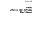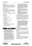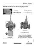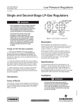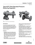
1
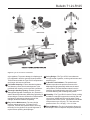
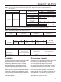
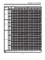
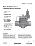
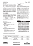
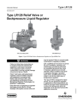
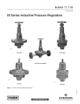
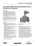
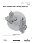
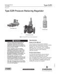
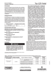
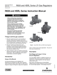
Bulletin 71.2:LR125
November 2014
Type LR125 Pressure Reducing Liquid Regulator
• Rugged design
• Reliable
• Thoroughly tested
• Internally actuated
• Compact
• 1, 2, 3, 4 in. body sizes
• Recommended for water
and oil applications
• Full SST construction
available for harsh
environments
• API 614 Compliant
Figure 1. Type LR125 Pressure Reducing Liquid Regulator
Features and Benefits
The Type LR125 pilot-operated, pressure reducing
regulator is designed for liquid industrial/commercial
applications. The Type LR125 provides smooth
operation, tight shutoff and long life. Its internally
actuated metal plug eliminates disadvantages
associated with flexible element style regulators, and
the specially engineered flow path deflects debris,
protecting the seat from damage and erosion. The
Type LR125 is used in conjunction with a Type MR95H
pilot and Type 112 restrictor. An internal inlet strainer
prevents large particles from entering the main valve,
limiting damage to internal parts.
1
Tight Shutoff—The Type LR125 uses a diaphragm
and metal plug, eliminating the disadvantages of
flexible element style regulators. When open, the
metal plug deflects particles and debris away from
the diaphragm. The result is enhanced resistance to
particle erosion, which provides excellent shutoff over
an extended life. When closed, loading pressure and
the main spring push the diaphragm onto the taperededged seat on the cage.
www.fisherregulators.com
D103575X012
Introduction
Bulletin 71.2:LR125
Specifications
The Specifications section lists the specifications for the Type LR125 regulator. Factory specification is stamped
on the nameplate fastened on the regulator at the factory.
Main Valve Body Sizes, End Connection Styles and
Structural Design Ratings(1)(2)
See Table 1
Maximum Inlet Pressures(1)
Type LR125 Main Valve: See Table 1
Type MR95H Pilot: See Table 2
Type 112 Restrictor: 1500 psig / 103 bar
Maximum Outlet Pressure
Type LR125 Main Valve: See Table 1
Type MR95H Pilot: See Table 2
Outlet (Control) Pressure Ranges
See Table 3
Main Valve Plug Travel
1 in. / DN 25: 0.37 in. / 9.4 mm
2 in. / DN 50: 0.68 in. / 17 mm
3 in. / DN 80: 0.98 in. / 25 mm
4 in. / DN 100: 1.19 in. / 30 mm
Main Valve Minimum Differential Pressures(1)
See Table 5
Temperature Capabilities(1)
See Table 4
Main Valve Flow Direction
Up through the center of the cage and down
through the cage slots
Main Valve Internal Inlet Strainer Sizes
1 in. / DN 25: 12 Mesh (0.0661 in. / 1.68 mm)(3)
2, 3 and 4 in. / DN 50, 80 and 100:
10 Mesh (0.0787 in. / 2 mm)(3)
Regulating Capacities
See Table 11
Flow and IEC Sizing Coefficients
Type LR125 Main Valve: See Table 6
Type MR95H Pilot: See Table 7
Type 112 Restrictor: See Table 8
Pressure Registration
External: 1/2 NPT
Spring Case Vent
Type Y602-12
Approximate Weights
See Table 9
Options
• Pre-piped Pilot Supply
• Travel Indicator
Construction Materials
Type LR125 Main Valve
Body: WCC Steel, CF8M or CF3M Stainless Steel
Bonnet: Steel or Stainless Steel
Bonnet Bushing: Steel or Stainless Steel
Cage: Stainless steel
Spring: Stainless steel
Top Plug: Stainless steel
Bottom Plug: Stainless steel
Internal Inlet Strainer: Stainless steel
Diaphragm: Nitrile (NBR) or Fluorocarbon (FKM)
O-rings: Nitrile (NBR) or Fluorocarbon (FKM)
Flanged Locknut: Stainless Steel
Backup Rings: Polytetrafluoroethylene (PTFE)
Upper Spring Seat: Stainless steel
Indicator Protector and Cover: Plastic
Indicator Stem: Stainless steel
Indicator Fitting: Stainless steel
Travel Indicator Plug: Stainless steel
Type MR95H Pilot
Body: WCC Steel or CF8M Stainless Steel
Spring Case: WCC Steel or CF8M Stainless Steel
Orifice: Stainless Steel
Diaphragm: Neoprene (CR) or Fluorocarbon (FKM)
Disk: Nitrile (NBR) or Fluorocarbon (FKM)
Mounting Parts
Pilot Mounting Pipe Nipple: Plated steel or
Stainless steel
Pipe Fittings: Plated steel or Stainless steel
Tubing: Stainless Steel
Type 112 Restrictor
Body: 15-5 Stainless Steel
Groove Valve: Stainless steel
Retainer: Stainless steel
Pipe Plug: Stainless steel
O-rings: Nitrile (NBR) or Fluorocarbon (FKM)
1. The pressure/temperature limits in this Bulletin and any applicable standard or code limitation should not be exceeded.
2. Ratings and end connections other than ASME standards can usually be provided; contact your local Sales Office.
3. Nominal sieve opening
2
3
Debris Protection—The specially engineered flow
path, along with the metal plug, allows flow through the
regulator without seat impingement. The addition of an
internal inlet strainer prevents large particles from entering
the regulator, minimizing damage to internal p arts.
High Accuracy—Multiple control pressure ranges
offered by Type MR95H pilot and lower accuracy class
2
inherent to pilot operated pressure regulator design
provide the Type LR125 with tight and accurate control.
4
Long Life—The robust design of the Type LR125 with
its metal plug and specially engineered flow path allows
flow through the regulator without seat impingement.
The diaphragm design eliminates the possibility of
taking a “set”, a common problem with flexible element
Bulletin 71.2:LR125
3
7
7
W5092
W7398
TYPE MR95H PILOT
8
TRIM PACKAGE
4
11
9
TYPE MR95H PILOT
10
1
5
6
12
2
W7345
W7344
TYPE LR125 PRESSURE REDUCING REGULATOR
Figure 2. Type LR125 Features and Benefits
style regulators. To prevent damage, the diaphragm is
fully supported in both the open and closed positions.
These features enable the Type LR125 components to
work longer with less wear and tear.
5
Full Usable Capacity—Fisher® branded regulators
are laboratory tested. One hundred percent of the
published flow capacity can be used with confidence.
6
Thorough Laboratory Testing—Emerson Process
Management Regulator Technologies, Inc. (Emerson™)
state-of-the-art flow laboratory allows thorough testing of
all new designs. Tests are conducted on Fisher branded
regulators for performance features such as flow,
strength, shutoff and material compatibility.
7
Easy In-Line Maintenance—Top-entry design
reduces maintenance time. Trim parts can be
inspected, cleaned and replaced without removing
the body from the pipeline. No special alignment is
required when replacing the diaphragm.
8
O-ring Design—The Type LR125 uses elastomer
O-rings instead of gaskets, reducing maintenance and
assembly time.
9
In-Service Travel Indicator—The optional travel
indicator responds to the precise movement of the
diaphragm and plug assembly and shows the actual
valve position. The travel indicator makes in-service
inspection and troubleshooting easy. Also, it can be used
for remote alarming and monitoring stem position.
10
Versatility—The Type LR125 uses the E-body, making
available the standard construction materials and end
connections (ASME and EN) used by other E-body
regulators and control valves. Type MR95H can handle
inlet pressures up to 300 psig / 20.7 bar and outlet
pressures from 15 to 150 psig / 1.0 to 10.3 bar.
11
Easy-to-Maintain—The pilot is designed to allow quick
and simple in-line trim inspection and parts replacement.
3
Bulletin 71.2:LR125
TYPE MR95H PILOT
TYPE 112 RESTRICTOR
CONTROL SPRING
DIAPHRAGM
SUPPLY LINE
VALVE PLUG
MAIN SPRING
DIAPHRAGM AND
PLUG ASSEMBLY
M1215
INLET PRESSURE
INTERNAL STRAINER
OUTLET PRESSURE
ATMOSPHERIC PRESSURE
LOADING PRESSURE
TYPE LR125 WITH TYPE MR95H PILOT AND TYPE 112 RESTRICTOR
Figure 3. Type LR125 Operational Schematic
12
Powder Paint Coating—Carbon steel body is powder
paint coated providing superior impact, abrasion and
corrosion resistance.
Pilot Type Description
Type MR95H—High-pressure pressure reducing pilot
for 15 to 150 psig / 1.0 to 10.3 bar outlet pressures.
Designed to handle inlet pressures up to 300 psig /
20.7 bar.
Principle of Operation
As long as the outlet (control) pressure is above the
outlet pressure setting, the pilot valve plug or disk
remains closed (Figure 3). Force from the main spring, in
addition to inlet pressure bleeding through the restrictor,
provide downward loading pressure to keep the main
valve diaphragm and plug assembly tightly shutoff.
4
When the outlet pressure decreases below the pilot
outlet pressure setting, the pilot plug or disk assembly
opens. Loading pressure bleeds downstream through
the pilot faster than it can be replaced through the
supply line. This reduces loading pressure on top of
the main valve diaphragm and plug assembly and
lets the unbalanced force between inlet and loading
pressure overcome the main spring force to open the
Type LR125 diaphragm and plug assembly.
As the outlet pressure rises toward the outlet pressure
setting, it compresses the pilot diaphragm against
the pilot control spring and lets the pilot valve plug
or disk close. Loading pressure begins to build up
on the Type LR125 diaphragm and plug assembly.
The loading pressure, along with force from the main
spring, pushes the diaphragm and plug assembly onto
the tapered-edge seat, producing tight shutoff.
Bulletin 71.2:LR125
Table 1. Type LR125 Main Valve Body Sizes, End Connection Styles, Structural Design Ratings and Maximum Operating
Inlet Pressures(1)
MAIN VALVE BODY SIZE
In.
MAIN VALVE
BODY MATERIAL
DN
psig
25, 50, 80 and 100
CF8M Stainless steel
MAXIMUM OPERATING
INLET PRESSURE(3)
bar
psig
bar
1500
103
300
20.7
290
20.0
290
20.0
CL300 RF
750
51.7
300
20.7
NPT or SWE
(1 and 2 in. only)
CL150 RF
WCC Steel
1, 2, 3 and 4
STRUCTURAL DESIGN
RATING(3)
END CONNECTION STYLE(2)
CL600 RF
1500
103
PN 16/25/40 RF(4)
NPT
(1 and 2 in. only)
CL150 RF
580
40.0
1440
99.2
300
20.7
275
19.0
275
19.0
CL300 RF
720
49.6
CL600 RF
1440
99.2
300
20.7
PN 16/25/40 RF(4)
580
40.0
1. The pressure/temperature limits in this Bulletin and any applicable standard or code limitation should not be exceeded.
2. Ratings and end connections for other than ASME standard can usually be provided. Contact your local Sales Office for assistance.
3. Maximum cold working pressure (CWP) per ASME B16.34 or product Bulletin limit, whichever is lowest. Temperature may decrease these maximum pressures.
4. Not available for 4 in. / DN 100 body size.
Table 2. Type MR95H Pilot Maximum Cold Working Pressure(1)(2)
BODY SIZE
BODY AND SPRING CASE MATERIAL
Steel
Stainless steel
1/2 NPT
MAXIMUM INLET PRESSURE
300 psig / 20.7 bar
300 psig / 20.7 bar
MAXIMUM OUTLET PRESSURE
300 psig / 20.7 bar
300 psig / 20.7 bar
1. The pressure/temperature limits in this Bulletin, and any applicable standard or code limitation should not be exceeded.
2. Temperature and/or the body end connection may decrease these maximum pressures.
Table 3. Outlet (Control) Pressure Ranges
PILOT
Type MR95H
OUTLET PRESSURE RANGE
SPRING WIRE DIAMETER
SPRING FREE LENGTH
psig
bar
In.
mm
In.
mm
SPRING PART NUMBER
AND COLOR
15 to 30
25 to 75
70 to 150
1.0 to 2.1
1.7 to 5.2
4.8 to 10.3
0.207
0.234
0.283
5.26
5.94
7.19
2.50
2.60
2.44
63.5
65.9
62.0
ERCA04288A0 Yellow
ERAA01910A0 Green
ERAA01911A0 Red
Table 4. Diaphragm Material Selection Information
Liquid Temperature
General Applications
17E68 NITRILE (NBR)
17E97 NITRILE (NBR)
17E88 FLUOROCARBON (FKM)
-20 to 150°F / -29 to 66°C
0 to 150°F / -18 to 66°C
0 to 250°F / -18 to 121°C(1)
Best for low pressure
differential and cold temperature
service applications.
Best for abrasive or
erosive service applications.
Best for high temperature
applications.
Fair
Excellent
Good
Heavy Particle Erosion
1. Fluorocarbon (FKM) is limited to 200°F / 93°C in hot water.
Installation
Overpressure Protection
The robust design of the Type LR125 allows this regulator
to be installed indoors or outdoors. This regulator
is designed to withstand the elements. The powder
paint coating protects regulator against minor impacts,
abrasions and c orrosion. When installed outdoors,
the Type LR125 does not require protective housing.
However, the Type MR95H pilot should be oriented so
that the pilot spring case vent is pointed down. Otherwise,
make sure the vent is protected so that rain, moisture,
insects or any debris will not accumulate inside or block
the vent assembly. When installed indoors, install remote
venting of the pilot spring case as required by applicable
codes and regulations.
Overpressuring any portion of a regulator or associated
equipment may cause personal injury, leakage
or property damage due to bursting of pressurecontaining parts. Provide appropriate pressure relieving
or pressure limiting devices to ensure that the limits in
the Specifications section are not exceeded. Common
methods of external overpressure protection include
relief valves, monitoring regulators, shutoff devices
and series regulation. Regulator operation within
ratings does not prevent the possibility of damage from
external sources or from debris in the pipeline. Install
additional strainer or filter upstream of the regulator for
applications with high levels of debris.
5
Bulletin 71.2:LR125
CAVITATION PREDICTION
150 /
10.3
135 /
9.3
120 /
8.3
OUTLET PRESSURE (P2)
psig / bar
105 /
7.2
90 /
6.2
75 /
5.2
60 /
4.1
45 /
3.1
30 /
2.1
15 /
1.0
0
30 /
2.1
60 /
4.1
90 /
6.2
120 /
8.3
150 /
10.3
180 /
12.4
210 /
14.5
240 /
16.5
270 /
18.6
300 /
20.7
INLET PRESSURE (P1)
psig / bar
CONTINUOUS SERVICE REGION
INTERMITTENT SERVICE REGION
FULL CAVITATION REGION
Figure 4. Cavitation Sizing for Water
Table 5. Main Valve Minimum Differential Pressures(1)
MAIN VALVE
BODY SIZE
In.
DN
1
25
2
50
3
80
4
100
MINIMUM DIFFERENTIAL, PERCENT OF CAPACITY
DIAPHRAGM
For 90% Capacity
For 100% Capacity
Diaphragm Code
Diaphragm Material
psid
bar d
psid
bar d
17E68 (standard)
Nitrile (NBR), Low Minimum Differential
30
2.1
30
2.1
17E97
Nitrile (NBR), High Erosion Resistance
35
2.5
35
2.5
17E88
Fluorocarbon (FKM), High Temperature Capability
30
2.1
30
2.1
17E68 (standard)
Nitrile (NBR), Low Minimum Differential
18
1.2
19
1.3
17E97
Nitrile (NBR), High Erosion Resistance
24
1.7
24
1.7
17E88
Fluorocarbon (FKM), High Temperature Capability
18
1.2
19
1.3
17E68 (standard)
Nitrile (NBR), Low Minimum Differential
21
1.5
28
1.9
17E97
Nitrile (NBR), High Erosion Resistance
23
1.6
23
1.6
17E88
Fluorocarbon (FKM), High Temperature Capability
21
1.5
28
1.9
17E68 (standard)
Nitrile (NBR), Low Minimum Differential
16
1.1
30
2.1
17E97
Nitrile (NBR), High Erosion Resistance
16
1.1
34
2.3
17E88
Fluorocarbon (FKM), High Temperature Capability
16
1.1
30
2.1
1. See Table 1 for structural design ratings and Table 2 for Type MR95H pilot rating.
Table 6. Flow and Sizing Coefficients for Type LR125 Main Valve at 100% Capacity
MAIN VALVE BODY SIZE
6
REGULATING COEFFICIENTS
WIDE-OPEN COEFFICIENTS
In.
DN
CV
C1
CV
C1
1
25
14.8
33.4
15.2
33.5
Km
0.88
IEC SIZING COEFFICIENTS
XT
FD
FL
0.706
0.06
0.94
2
50
50.8
37.2
52.4
37.2
0.92
0.875
0.09
0.96
3
80
91.4
38.8
94.1
38.8
0.94
0.952
0.09
0.97
4
100
147
38.7
151
38.7
0.85
0.947
0.09
0.92
Bulletin 71.2:LR125
Table 7. Flow and Sizing Coefficients for Type MR95H Pilot
BODY SIZE,
IN. / DN
WIDE-OPEN COEFFICIENT
1/2 / 15
2.9
IEC SIZING COEFFICIENTS
C1
Km
35.5
0.79
Cv
XT
FD
FL
0.797
0.70
0.89
Km = FL2
Table 8. Type 112 Restrictor Flow Coefficients
RESTRICTOR SETTING
Cv
Setting 2
0.03
Setting 4
0.07
Setting 6
0.14
Setting 8
0.17
C1
35
Table 9. Approximate Weights Including Type MR95H Pilot and Restrictor
MAIN VALVE BODY,
LBS / kg
BODY SIZE
In.
DN
NPT or SWE
CL150 RF
CL300 RF
CL600 RF
1
25
22 / 10
24 / 11
28 / 13
32 / 15
2
50
51 / 23
54 / 24
58 / 26
65 /29
3
80
103 / 47
107 / 49
110 / 50
123 / 56
4
100
139 / 63
145 / 66
159 / 72
192 / 87
Cavitation Sizing
Note
The cavitation sizing graph in Figure 4 applies to water only. For cavitation
sizing for other liquids, contact your
local Sales Office.
Use Figure 4 to determine cavitation sizing of
Type L
R125. The Cavitation Prediction Curve depicts
P1 and P2 combinations where cavitation is likely
to occur. The curve shape was determined through
analysis and lab confirmation on water. Determine the
desired inlet pressure and outlet pressure of the system
and find the intersection of those values on the graph.
No Cavitation Region—Cavitation is not expected
in this region. Damage to regulator components and
piping is highly unlikely as a result of cavitation.
Note
Emerson™
denies responsibility for
damage and voids the warranty if the
product is used within the Cavitation
Region (see Figure 4).
Cavitation Region—Cavitation may occur. Damage
to regulator components and piping is possible. The
risk of damage increases as P1 and P2 move down
and to the right on the table. Cavitation damage can
be avoided by dividing the total pressure drop into
stages so that the P1 and P2 combination falls into the
“No Cavitation Region” at every stage.
Capacity Information
Note
Flow capacities are laboratory verified;
therefore, regulators may be sized for
100% flow published capacities. It is not
necessary to reduce published capacities.
The capacity information on the following pages is based
on four % droop, 10%, 20%, 30% and 40%. Droop is
the negative control deviation or pressure offset below
the setpoint of the regulator.
Table 10 shows Cv values at different % droop and
selected inlet pressures and outlet pressure settings.
Table 11 shows the liquid regulating capacities of the
Type LR125 regulator at selected inlet pressures and outlet
pressure settings. Flows are in gallons per minute (GPM)
and liters per minute (L/min) of water.
7
Bulletin 71.2:LR125
Table 10. Cv(1) at % Droop (Pressure Offset Below Setpoint)(2)
SPRING
RANGE AND
COLOR
15 to 30 psig /
1.0 to 2.1 bar
Yellow
25 to 75 psig /
1.7 to 5.2 bar
Green
OUTLET
PRESSURE
psig bar
15
1.0
20
1.4
30
2.1
25
1.7
50
3.4
75
5.2
70
4.8
100
6.9
125
8.6
150
10.3
70 to 150 psig /
4.8 to 10.3 bar
Red
INLET
psig
45
50
60
65
50
60
70
75
60
75
90
100
55
75
80
90
80
100
125
150
110
125
150
175
200
100
125
150
175
190
200
130
150
175
200
250
275
155
175
200
250
275
300
180
200
225
250
275
300
bar
3.1
3.4
4.1
4.4
3.4
4.1
4.8
5.1
4.1
5.1
6.1
6.8
3.7
5.1
5.4
6.1
5.4
6.8
8.5
10.2
7.5
8.5
10.2
11.9
13.6
6.8
8.5
10.2
11.9
12.9
13.6
8.8
10.2
11.9
13.6
17.0
18.7
10.5
11.9
13.6
17.0
18.7
20.4
12.2
13.6
15.3
17.0
18.7
20.4
1 IN. / DN 25
10%
14.8
14.8
14.8
14.8
14.8
14.8
14.8
14.8
14.8
14.8
14.8
14.8
14.8
14.8
14.8
14.8
14.8
14.8
14.8
14.8
14.8
14.8
14.8
14.7
14.2
14.8
14.8
14.7
14.6
14.5
14.5
14.8
14.8
14.8
14.8
14.2
13.9
14.8
14.8
14.8
14.8
14.7
14.5
14.8
14.8
14.8
14.8
14.8
14.8
20%
14.8
14.8
14.8
14.8
14.8
14.8
14.8
14.8
14.8
14.8
14.8
14.8
14.8
14.8
14.8
14.8
14.8
14.8
14.8
14.8
14.8
14.8
14.8
14.8
14.5
14.8
14.8
14.8
14.8
14.8
14.8
14.8
14.8
14.8
14.8
14.2
13.7
14.8
14.8
14.8
14.8
14.6
14.3
14.8
14.8
14.8
14.8
14.8
14.8
30%
14.8
14.8
14.8
14.8
14.8
14.8
14.8
14.8
14.8
14.8
14.8
14.8
14.8
14.8
14.8
14.8
14.8
14.8
14.8
14.8
14.8
14.8
14.8
14.8
14.6
14.8
14.8
14.7
14.8
14.8
14.8
14.8
14.8
14.8
14.8
14.2
13.7
14.8
14.8
14.8
14.8
14.6
14.3
14.8
14.8
14.8
14.8
14.8
14.8
2 IN. / DN 50
40%
14.8
14.8
14.8
14.8
14.8
14.8
14.8
14.8
14.8
14.8
14.8
14.8
14.8
14.8
14.8
14.8
14.8
14.8
14.8
14.8
14.8
14.8
14.8
14.8
14.5
14.8
14.8
14.8
14.8
14.8
14.8
14.8
14.8
14.8
14.8
14.2
13.7
14.8
14.8
14.8
14.8
14.6
14.3
14.8
14.8
14.8
14.8
14.8
14.8
10%
39.7
39.2
38.3
37.8
50.8
48.5
46.1
44.9
50.8
50.8
50.8
47.6
50.8
50.8
50.8
50.8
49.0
49.1
49.2
49.3
50.8
50.8
49.8
45.3
40.7
50.5
46.1
41.6
44.6
46.4
47.7
50.8
50.1
48.4
46.7
43.2
41.5
50.8
50.8
45.9
43.6
42.5
41.4
45.4
45.0
44.5
44.0
43.5
43.1
20%
44.2
44.5
44.9
45.2
50.8
50.7
50.0
49.7
50.8
50.8
50.8
50.8
50.8
50.8
50.8
50.8
50.1
50.1
50.0
50.0
50.8
50.8
49.8
46.5
43.1
49.4
46.0
42.7
46.0
47.9
49.2
50.0
49.5
48.9
48.3
47.1
46.5
50.8
50.8
47.5
46.4
45.8
45.3
47.2
46.7
46.2
45.7
45.2
44.7
30%
48.3
48.4
48.5
48.6
50.8
50.7
50.5
50.3
50.8
50.8
50.8
50.6
50.8
50.8
50.8
50.8
49.9
50.0
50.1
50.2
50.8
50.8
49.5
46.4
43.3
49.3
46.6
43.8
46.0
47.3
48.2
49.6
49.2
48.7
48.2
47.3
46.8
50.8
50.8
48.3
46.9
46.3
45.6
49.0
48.3
47.5
46.6
45.8
44.9
3 IN. / DN 80
40%
50.8
50.6
50.0
49.8
50.8
50.4
49.9
49.7
50.8
50.7
50.2
49.8
50.8
50.6
50.5
50.3
49.7
49.8
50.1
50.3
50.8
50.8
49.9
47.1
44.2
49.9
47.5
45.0
46.7
47.7
48.4
49.7
49.3
48.8
48.4
47.4
46.9
50.8
50.6
48.4
47.0
46.3
45.6
49.0
48.3
47.5
46.6
45.7
44.9
10%
83.0
83.3
84.1
84.5
91.4
91.4
91.4
91.2
91.4
91.4
91.4
91.4
91.4
91.4
91.4
91.4
91.4
91.4
91.4
91.4
91.4
91.4
91.4
86.1
80.6
91.4
87.7
82.8
85.2
86.7
87.7
91.4
91.4
90.7
88.1
82.8
80.2
91.4
91.4
88.4
85.2
83.6
82.0
89.3
88.8
88.2
87.5
86.9
86.3
20%
89.2
89.6
90.4
90.8
91.4
91.4
91.4
91.4
91.4
91.4
91.4
91.4
91.4
91.4
91.4
91.4
91.4
91.4
91.4
91.4
91.4
91.4
91.4
87.9
83.4
91.4
88.6
84.0
87.0
88.8
90.0
91.4
91.4
91.4
90.3
86.2
84.1
91.4
91.4
90.5
87.7
86.3
85.0
91.3
90.7
90.0
89.3
88.5
87.8
30%
91.4
91.4
91.4
91.4
91.4
91.4
91.4
91.4
91.4
91.4
91.4
91.4
91.4
91.4
91.4
91.4
91.4
91.4
91.4
91.4
91.4
91.4
91.4
88.0
84.0
91.4
89.5
84.9
87.2
88.5
89.5
91.4
91.4
91.4
90.4
86.5
84.5
91.4
91.4
91.2
88.2
86.7
85.2
91.4
91.4
90.9
89.9
88.9
87.9
4 IN. / DN 100
40%
91.4
91.4
91.4
91.3
91.4
91.4
91.4
91.4
91.4
91.4
91.4
91.4
91.4
91.4
91.4
91.4
91.4
91.4
91.4
90.9
91.4
91.4
91.4
88.7
84.6
91.4
91.4
86.6
87.9
88.8
89.3
91.4
91.4
91.4
90.4
86.5
84.6
91.4
91.4
91.2
88.1
86.6
85.1
91.4
91.4
90.9
89.8
88.6
87.4
10%
133.4
134.0
135.2
135.9
147.0
147.0
147.0
146.7
147.0
147.0
147.0
147.0
147.0
147.0
147.0
147.0
147.0
147.0
147.0
147.0
147.0
147.0
147.0
138.5
129.6
147.0
141.1
133.1
137.1
139.4
141.0
147.0
147.0
145.9
141.6
133.2
129.0
147.0
147.0
142.2
137.0
134.4
131.8
143.5
142.8
141.8
140.8
139.8
138.8
1. Type LR125 on liquid service with 1/2 NPT Type MR95H Pilot, 100% Cage Capacity with internal inlet strainer and Type 112 Restrictor Setting of “4”.
2. Values published in this table are laboratory tested and are presented based on % droop (negative control deviation only) or pressure offset below setpoint.
Exceeds recommended maximum pressure drop ratio of 0.65.
8
20%
143.4
144.1
145.4
146.0
147.0
147.0
147.0
147.0
147.0
147.0
147.0
147.0
147.0
147.0
147.0
147.0
147.0
147.0
147.0
147.0
147.0
147.0
147.0
141.3
134.2
147.0
142.5
135.0
139.9
142.8
144.7
147.0
147.0
147.0
145.2
138.6
135.3
147.0
147.0
145.5
141.1
138.9
136.6
146.8
145.9
144.7
143.6
142.4
141.2
30%
147.0
147.0
147.0
147.0
147.0
147.0
147.0
147.0
147.0
147.0
147.0
147.0
147.0
147.0
147.0
147.0
147.0
147.0
147.0
147.0
147.0
147.0
147.0
141.6
135.1
147.0
144.0
136.5
140.2
142.4
143.9
147.0
147.0
147.0
145.4
139.1
135.9
147.0
147.0
146.6
141.9
139.5
137.1
147.0
147.0
146.3
144.7
143.0
141.4
40%
147.0
147.0
147.0
146.8
147.0
147.0
147.0
146.1
147.0
147.0
147.0
147.0
147.0
147.0
147.0
147.0
147.0
147.0
147.0
146.2
147.0
147.0
147.0
142.6
136.0
147.0
147.0
139.2
141.4
142.8
143.7
147.0
147.0
147.0
145.3
139.2
136.1
147.0
147.0
146.7
141.8
139.3
136.8
147.0
147.0
146.2
144.4
142.5
140.6
Bulletin 71.2:LR125
Table 11. Capacity(1), Water (GPM / L/min) for 1 and 2 in. / DN 25 and 50 Bodies at % Droop (Pressure Offset Below Setpoint)(2)
SPRING
RANGE AND
COLOR
OUTLET
PRESSURE
psig
15
15 to 30 psig /
1.0 to 2.1 bar
Yellow
20
30
25
25 to 75 psig /
1.7 to 5.2 bar
Green
50
75
70
100
bar
1.0
1.4
2.1
1.7
3.4
5.2
4.8
6.9
70 to 150 psig /
4.8 to 10.3 bar
Red
125
150
8.6
10.3
1 IN. / DN 25
INLET
10%
20%
2 IN. / DN 50
30%
40%
10%
20%
30%
40%
psig
bar
GPM L/min GPM L/min GPM L/min GPM L/min GPM L/min GPM L/min GPM L/min GPM L/min
45
3.1
83
314
85
322
87
329
89
336
223
843
254
961
284
1074
305
1154
50
3.4
89
338
91
345
93
352
95
359
237
897
274
1037
304
1151
324
1226
60
4.1
101
382
103
388
104
394
106
400
261
989
311
1178
341
1292
357
1353
65
4.4
106
402
108
408
109
414
111
419
272
1028
329
1245
359
1358
372
1409
50
3.4
84
317
86
327
89
336
91
345
287
1088
296
1121
305
1154
313
1185
60
4.1
96
363
98
372
100
380
103
388
314
1190
336
1272
344
1302
349
1323
70
4.8
107
404
109
412
111
419
113
427
333
1259
368
1392
378
1429
380
1440
75
5.1
112
423
114
430
116
438
117
445
339
1284
382
1446
393
1487
394
1493
60
4.1
85
322
89
336
92
350
96
363
292
1105
305
1154
317
1201
329
1246
75
5.1
103
388
106
400
109
412
112
423
352
1332
363
1373
373
1413
383
1449
90
6.1
117
445
120
455
123
465
126
475
403
1526
413
1562
422
1597
426
1611
100
6.8
126
479
129
488
132
498
134
507
407
1541
443
1676
450
1703
451
1707
55
3.7
84
319
88
331
91
343
94
354
290
1096
301
1138
311
1178
321
1216
75
5.1
107
406
110
415
112
425
115
434
368
1393
377
1426
385
1458
392
1484
80
5.4
112
425
115
434
117
443
119
452
385
1458
394
1490
402
1520
407
1541
90
6.1
122
460
124
469
126
477
128
485
417
1580
425
1609
433
1637
435
1648
80
5.4
88
331
94
354
99
376
105
396
290
1097
317
1200
335
1267
351
1329
100
6.8
110
415
115
434
119
452
124
469
364
1378
388
1469
403
1526
417
1579
125
8.5
132
501
136
517
140
532
144
546
440
1665
461
1746
475
1798
488
1847
150
10.2
152
574
155
588
159
601
162
613
505
1912
524
1984
538
2037
551
2086
110
7.5
96
365
105
396
112
425
119
452
331
1254
359
1360
385
1458
410
1550
125
8.5
112
425
119
452
126
477
132
501
385
1458
410
1550
433
1637
454
1720
150
10.2
134
509
140
532
146
553
152
574
452
1711
472
1787
489
1851
511
1934
175
11.9
153
577
159
601
164
620
169
639
469
1776
498
1885
514
1945
537
2031
200
13.6
164
620
171
647
177
670
180
683
469
1775
510
1932
526
1992
551
2085
100
6.8
90
341
98
372
106
400
113
427
307
1163
327
1240
352
1334
380
1438
125
8.5
117
441
123
465
129
488
135
510
363
1373
382
1447
406
1537
432
1637
150
10.2
137
519
143
541
148
560
154
582
388
1469
414
1567
440
1666
468
1772
175
11.9
154
585
161
610
166
629
171
646
472
1788
501
1898
516
1953
539
2039
190
12.9
164
620
171
648
176
665
180
682
523
1981
555
2100
562
2126
580
2196
200
13.6
170
643
178
672
182
688
186
704
558
2111
591
2236
592
2240
608
2301
130
8.8
94
354
105
396
115
434
124
469
321
1216
353
1337
384
1454
416
1575
150
10.2
115
434
124
469
132
501
140
532
388
1469
414
1567
440
1666
468
1772
175
11.9
136
517
144
546
152
574
159
601
446
1688
476
1804
499
1889
524
1983
200
13.6
155
588
162
614
169
639
175
663
489
1853
529
2002
550
2081
572
2166
250
17.0
180
681
185
700
191
723
196
742
547
2071
614
2324
634
2400
653
2472
275
18.7
189
715
191
724
197
745
202
763
565
2138
649
2458
670
2535
687
2602
155
10.5
96
365
110
415
122
460
132
501
331
1254
377
1426
417
1580
454
1720
175
11.9
117
443
128
485
138
524
148
560
402
1520
440
1665
475
1799
506
1917
200
13.6
138
524
148
560
157
594
165
626
429
1623
475
1798
512
1938
541
2046
250
17.0
174
657
181
686
189
714
196
741
512
1937
568
2151
598
2265
622
2353
275
18.7
187
708
193
731
200
757
206
779
542
2053
606
2295
633
2398
655
2479
300
20.4
198
750
203
767
209
790
214
810
567
2148
640
2424
665
2516
684
2591
180
12.2
99
376
115
434
128
485
140
532
305
1153
365
1383
424
1607
465
1761
200
13.6
119
452
132
501
144
546
155
588
363
1374
418
1582
471
1783
507
1919
225
15.3
140
532
152
574
162
614
172
651
422
1599
474
1793
520
1968
552
2088
250
17.0
159
601
169
639
178
675
187
709
472
1788
521
1972
561
2125
589
2231
275
18.7
175
663
184
697
193
730
201
762
515
1950
562
2129
597
2258
622
2354
300
20.4
190
720
199
752
207
782
214
812
553
2093
599
2267
627
2373
650
2461
1. Type LR125 on liquid service with 1/2 NPT Type MR95H Pilot, 100% Cage Capacity with internal inlet strainer and Type 112 Restrictor Setting of “4”.
2. Values published in this table are laboratory tested and are presented based on % droop (negative control deviation only) or pressure offset below setpoint.
Exceeds recommended maximum pressure drop ratio of 0.65.
- continued -
9
Bulletin 71.2:LR125
Table 11. C
apacity(1), Water (GPM / L/min) for 3 and 4 in. / DN 80 and 100 Bodies at % Droop (Pressure Offset Below
Setpoint)(2) (continued)
SPRING
RANGE AND
COLOR
OUTLET
PRESSURE
psig
15
15 to 30 psig /
1.0 to 2.1 bar
Yellow
20
30
25
25 to 75 psig /
1.7 to 5.2 bar
Green
50
75
70
100
bar
1.0
1.4
2.1
1.7
3.4
5.2
4.8
6.9
70 to 150 psig /
4.8 to 10.3 bar
Red
125
150
8.6
10.3
INLET
3 IN. / DN 80
10%
20%
4 IN. / DN 100
30%
40%
10%
20%
30%
bar
GPM L/min GPM L/min GPM L/min GPM L/min GPM L/min GPM L/min GPM L/min GPM L/min
45
3.1
466
1762
512
1939
537
2032
548
2076
749
2835
824
3119
863
3268
882
3339
50
3.4
503
1906
552
2090
574
2174
585
2215
810
3065
888
3362
924
3497
941
3563
60
4.1
573
2171
626
2370
643
2434
653
2471
922
3491
1007
3812
1034
3915
1050
3974
65
4.4
606
2295
661
2502
675
2554
683
2586
975
3690
1063
4024
1085
4108
1099
4159
50
3.4
517
1957
533
2017
548
2076
563
2133
832
3148
857
3245
882
3339
906
3430
60
4.1
592
2242
606
2295
620
2347
633
2397
953
3606
975
3691
997
3774
1018
3855
70
4.8
659
2495
672
2542
684
2589
696
2635
1060
4013
1080
4089
1100
4164
1120
4238
75
5.1
689
2606
702
2658
714
2702
725
2746
1107
4192
1129
4274
1148
4346
1160
4390
60
4.1
525
1988
548
2076
571
2161
592
2242
844
3197
882
3339
918
3475
953
3606
75
5.1
633
2397
653
2471
672
2542
690
2612
1018
3855
1050
3974
1080
4089
1110
4201
90
6.1
725
2746
743
2811
759
2874
776
2936
1167
4417
1194
4521
1221
4622
1247
4722
100
6.8
781
2956
797
3016
812
3075
828
3133
1256
4754
1282
4851
1307
4946
1331
5039
55
3.7
521
1972
541
2047
560
2119
578
2188
838
3172
870
3292
900
3408
930
3519
75
5.1
662
2507
678
2566
693
2624
708
2680
1065
4032
1090
4127
1115
4220
1139
4310
80
5.4
693
2624
708
2680
723
2735
737
2789
1115
4220
1139
4310
1162
4399
1185
4486
90
6.1
751
2843
765
2895
778
2946
792
2996
1208
4572
1230
4656
1252
4738
1273
4819
80
5.4
541
2047
578
2188
613
2321
646
2447
870
3292
930
3519
986
3733
1039
3935
100
6.8
678
2566
708
2680
737
2789
765
2895
1090
4127
1139
4310
1185
4486
1230
4656
125
8.5
818
3095
843
3190
867
3282
891
3372
1315
4977
1355
5130
1395
5279
1433
5424
150
10.2
937
3545
959
3629
980
3710
996
3770
1506
5702
1542
5836
1576
5967
1602
6063
110
7.5
596
2256
646
2447
693
2624
737
2789
958
3628
1039
3935
1115
4220
1185
4486
125
8.5
693
2624
737
2789
778
2946
818
3095
1115
4220
1185
4486
1252
4738
1315
4977
150
10.2
830
3143
867
3282
903
3416
937
3545
1335
5054
1395
5279
1452
5495
1506
5702
175
11.9
893
3380
942
3566
974
3688
1011
3827
1436
5437
1515
5736
1567
5931
1626
6155
200
13.6
927
3511
987
3737
1020
3860
1053
3985
1492
5646
1588
6010
1640
6209
1693
6409
100
6.8
556
2105
606
2295
653
2471
696
2635
894
3385
975
3691
1050
3974
1120
4238
125
8.5
691
2614
736
2786
780
2954
833
3152
1111
4205
1184
4481
1255
4750
1339
5070
150
10.2
772
2923
814
3081
853
3228
900
3405
1242
4701
1309
4956
1372
5192
1447
5477
175
11.9
902
3414
949
3591
978
3704
1014
3839
1450
5490
1526
5776
1574
5956
1631
6175
190
12.9
977
3698
1028
3890
1051
3980
1080
4088
1571
5947
1653
6257
1691
6401
1737
6575
200
13.6
1026
3884
1080
4087
1099
4161
1123
4250
1650
6246
1737
6574
1768
6693
1806
6836
130
8.8
578
2188
646
2447
708
2680
765
2895
930
3519
1039
3935
1139
4310
1230
4656
150
10.2
708
2680
765
2895
818
3095
867
3282
1139
4310
1230
4656
1315
4977
1395
5279
175
11.9
836
3165
891
3372
937
3545
980
3710
1345
5090
1433
5424
1506
5702
1576
5967
200
13.6
924
3497
989
3743
1031
3901
1069
4047
1486
5624
1590
6019
1658
6275
1719
6509
250
17.0
1048
3967
1124
4253
1160
4392
1193
4515
1685
6380
1807
6841
1866
7063
1918
7261
275
18.7
1091
4131
1175
4447
1210
4580
1241
4696
1755
6644
1890
7153
1946
7367
1995
7553
155
10.5
596
2256
678
2566
751
2843
818
3095
958
3628
1090
4127
1208
4572
1315
4977
175
11.9
723
2735
792
2996
855
3236
914
3460
1162
4399
1273
4819
1375
5205
1470
5565
200
13.6
827
3131
905
3425
967
3660
1020
3860
1330
5035
1455
5509
1555
5887
1640
6208
250
17.0
999
3782
1074
4067
1124
4256
1166
4414
1607
6082
1728
6541
1808
6845
1875
7099
275
18.7
1065
4033
1142
4323
1188
4495
1225
4636
1714
6487
1837
6953
1910
7230
1970
7457
300
20.4
1122
4249
1201
4548
1243
4704
1276
4830
1805
6834
1932
7314
1999
7565
2052
7769
180
12.2
599
2266
707
2677
792
2996
867
3282
963
3645
1137
4306
1273
4819
1395
5279
200
13.6
716
2709
811
3072
891
3372
959
3629
1151
4357
1305
4940
1433
5424
1542
5836
225
15.3
836
3166
922
3491
996
3771
1056
3998
1345
5091
1483
5614
1602
6065
1699
6431
250
17.0
939
3554
1018
3853
1083
4100
1135
4298
1510
5716
1637
6196
1742
6593
1826
6912
275
18.7
1029
3894
1102
4172
1160
4390
1205
4562
1654
6262
1773
6711
1865
7060
1938
7337
300
20.4
1109
4198
1178
4459
1228
4648
1267
4797
1783
6751
1895
7172
1975
7476
2038
7715
1. Type LR125 on liquid service with 1/2 NPT Type MR95H Pilot, 100% Cage Capacity with internal inlet strainer and Type 112 Restrictor Setting of “4”.
2. Values published in this table are laboratory tested and are presented based on % droop (negative control deviation only) or pressure offset below setpoint.
Exceeds recommended maximum pressure drop ratio of 0.65.
10
40%
psig
Bulletin 71.2:LR125
TYPE MR95H PILOT
M
OPTIONAL
INDICATOR COVER
1/4 NPT
VENT
TYPE 112
RESTRICTOR
T
TRAVEL INDICATOR
COVER REMOVAL
CLEARANCE
1/2 NPT
CONTROL
LINE
CONNECTION
1/4 NPT PILOT
SUPPLY CONNECTION
E
D
D1
V
VALVE TRIM
REMOVAL
CLEARANCE
G
A
B
ERAA00985_B
TYPE LR125 WITH TYPE MR95H PILOT
Figure 5. Type LR125 Dimensions
Table 12. Type LR125 Dimensions
DIMENSIONS, IN. / mm
BODY SIZE
In.
DN
1
25
2
50
3
80
4
100
A
CL150 RF
CL300 RF
3.62 /
91.9
5.0 /
127.0
5.9 /
149.3
6.9 /
176.3
3.88 /
98.6
5.3 /
133.4
6.3 /
158.8
7.3 /
184.2
B
CL600 RF
CL150 RF
CL300 RF
CL600 RF
4.13 / 104.9
7.25 / 184.2
7.75 / 196.9
8.25 / 209.6
10.00 / 254.0
10.50 / 266.7
11.25 / 286.0
11.75 / 298.5
12.50 / 317.5
13.25 / 336.6
13.88 / 352.6
14.50 / 368.3
15.50 / 393.7
5.6 /
143.0
6.6 /
168.3
7.8 /
196.9
Ordering Information
Carefully review each specification, then complete
the Ordering Guide on this page. If a pilot setpoint
is not requested, the regulator will be factory set at
the approximate midrange. Please complete the
specifications worksheet at the bottom of the ordering
guide on page 12.
Ordering Guide
Body Size (Select One)
1 in. / DN 25***
2 in. / DN 50***
3 in. / DN 80***
4 in. / DN 100***
Body Material and End Connection Style (Select One)
WCC Steel Body
NPT (Available in 1 and 2 in. bodies only)***
SWE (Available in 1 and 2 in. bodies only)***
CL150 RF***
CL300 RF***
CL600 RF***
PN 16/25/40 RF* (Not available in 4 in. body)
_____________ specify rating
D
D1
E
G
7.40 /
189.0
9.00 /
229.0
13.30 /
338.0
14.70 /
373.0
5.40 /
137.0
6.89 /
175.0
9.33 /
236.9
10.47 /
265.9
11.39 /
289.3
11.65 /
295.9
13.68 /
347.5
15.24 /
387.1
2.40 /
60.0
3.10 /
79.0
3.80 /
97.0
5.10 /
130.0
M
WCC
Steel
8.10 /
205.8
8.18 /
207.8
8.66 /
220.0
9.52 /
241.8
CF8M
SST
8.10 /
205.8
9.18 /
233.2
9.66 /
245.4
9.52 /
241.8
T
V
2.97 /
75.4
2.00 /
51.0
3.80 /
97.0
3.80 /
97.0
9.40 /
238.8
11.00 /
279.4
15.00 /
381.0
17.00 /
431.8
CF8M Stainless Steel Body
NPT (Available in 1 and 2 in. bodies only)***
CL150 RF***
CL300 RF***
CL600 RF***
PN 16/25/40 RF* (Not available in 4 in. body)
_____________ specify rating
Main Valve Diaphragm Material (Select One)
17E68 Nitrile (NBR) (low minimum differential
capability) (standard)***
17E97 Nitrile (NBR) (high erosion resistant)***
17E88 Fluorocarbon (FKM)
(high temperature capability)**
Main Valve O-ring Material (Select One)
Nitrile (NBR) (standard)***
Fluorocarbon (FKM)**
Travel Indicator (Select One)
No (standard)***
Yes***
Inlet Body Tap (Select One)
Inlet body tap only (standard)***
Inlet body tap with pre-piped pilot supply***
Inlet/outlet body taps only***
Inlet/outlet body taps with pre-piped pilot supply and
pilot bleed***
11
Bulletin 71.2:LR125
Ordering Guide (continued)
Pilot Diaphragm Material (Select One)
Neoprene (CR) (standard)***
Fluorocarbon (FKM)**
Pilot Valve Plug Material (Select One)
Nitrile (NBR) (standard)***
Fluorocarbon (FKM)***
Type MR95H Pilot Outlet Pressure Range (Select One)
15 to 30 psig / 1.0 to 2.1 bar, Yellow***
25 to 75 psig / 1.7 to 5.2 bar, Green***
70 to 150 psig / 4.8 to 10.3 bar, Red***
Main Valve Replacement Parts Kit (Optional)
Yes, send one diaphragm cartridge and O-rings kit to
match this order.
Pilot Replacement Parts Kit (Optional)
Yes, send one replacement kit to match this order.
Regulators Quick Order Guide
***
**
*
Readily Available for Shipment
Allow Additional Time for Shipment
Special Order, Constructed from Non-Stocked Parts.
Consult your local Sales Office for Availability.
Availability of the product being ordered is determined by the component with the
longest shipping time for the requested construction.
Specification Worksheet
Application:
Specific Use____________________________________
Line Size______________________________________
Fluid Type_____________________________________
Specific Gravity_________________________________
Temperature_ __________________________________
Does the Application Require Overpressure Protection? Yes No
Pressure:
Maximum Inlet Pressure__________________________
Minimum Inlet Pressure___________________________
Differential Pressure_ ____________________________
Set Pressure___________________________________
Maximum Flow_ ________________________________
Accuracy Requirements:
Less Than or Equal To:
5% 10% 20% 40%
Construction Material Requirements (if known):
_____________________________________________
_____________________________________________
Industrial Regulators
Natural Gas Technologies
TESCOM
Emerson Process Management
Regulator Technologies, Inc.
Emerson Process Management
Regulator Technologies, Inc.
Emerson Process Management
Tescom Corporation
USA - Headquarters
McKinney, Texas 75070 USA
Tel: +1 800 558 5853
Outside U.S. +1 972 548 3574
USA - Headquarters
McKinney, Texas 75070 USA
Tel: +1 800 558 5853
Outside U.S. +1 972 548 3574
USA - Headquarters
Elk River, Minnesota 55330-2445, USA
Tels: +1 763 241 3238
+1 800 447 1250
Asia-Pacific
Shanghai 201206, China
Tel: +86 21 2892 9000
Asia-Pacific
Singapore 128461, Singapore
Tel: +65 6770 8337
Europe
Selmsdorf 23923, Germany
Tel: +49 38823 31 287
Europe
Bologna 40013, Italy
Tel: +39 051 419 0611
Europe
Bologna 40013, Italy
Tel: +39 051 419 0611
Chartres 28008, France
Tel: +33 2 37 33 47 00
Asia-Pacific
Shanghai 201206, China
Tel: +86 21 2892 9499
Middle East and Africa
Dubai, United Arab Emirates
Tel: +971 4811 8100
Middle East and Africa
Dubai, United Arab Emirates
Tel: +971 4811 8100
For further information visit www.fisherregulators.com
The Emerson logo is a trademark and service mark of Emerson Electric Co. All other marks are the property of their prospective owners. Fisher is a mark owned by Fisher Controls International LLC,
a business of Emerson Process Management.
The contents of this publication are presented for informational purposes only, and while every effort has been made to ensure their accuracy, they are not to be construed as warranties or
guarantees, express or implied, regarding the products or services described herein or their use or applicability. We reserve the right to modify or improve the designs or specifications of such
products at any time without notice.
Emerson Process Management Regulator Technologies, Inc. does not assume responsibility for the selection, use or maintenance of any product. Responsibility for proper selection, use and
maintenance of any Emerson Process Management Regulator Technologies, Inc. product remains solely with the purchaser.
©Emerson Process Management Regulator Technologies, Inc., 2012, 2014; All Rights Reserved