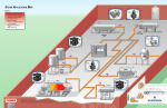
1
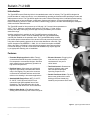
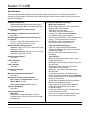
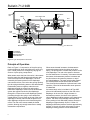
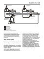
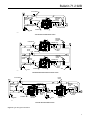
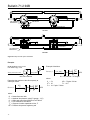
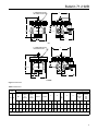
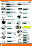
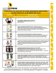
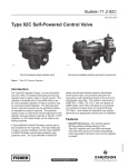
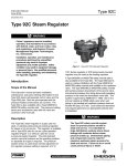
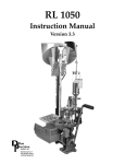
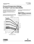
Bulletin 71.2:92B
September 2014
Type 92B Pressure Reducing Valve
• Extended Diaphragm Service Life
• Two-Path Control
• Elevated Actuator
• Resilient Seats
• Bellows Stem Guide
• Double Post Stem Guide
W8264
• Standard ANSI Face-to-Face Life
D101342X012
Figure 1. Type 92B Pressure Reducing Valve
www.fisherregulators.com
Bulletin 71.2:92B
Introduction
The Type 92B Pressure Reducing Valve is the standard steam valve for industry. The Type 92B is designed to
provide decades of continuous service. It can withstand dirty operating environments while providing accurate and
stable pressure control. The Type 92B is applied as a main Pressure Reducing Valve in industrial process heating
applications such as heat exchangers, evaporators, digesters and reactors. Commercial applications include
Pressure Reducing Valves for meter runs found in district energy systems, hot water heat exchangers, absorption
chillers and boiler deaerator tanks.
The Type 92B is rated for inlet pressure up to 300 psig / 20.7 bar and inlet temperatures to
600°F / 316°C. Maximum controlled outlet pressure is 250 psig / 17.2 bar. A large
actuator and heavy main spring ensures high accuracy and stability over its entire
steam flow range.
A safety override pilot is available for the Type 92B pressure reducing valve.
The Type 92B pilot is used in a series installation with the Type 6492HM safety
override pilot installed on the upstream valve. The Type 6492HM safety override
pilot senses pressure downstream of the second valve and prevents pressure from
rising above safe operating pressure in the event the downstream valve fails. This
system is approved by ASME B31.1-1989, 122.14.2.A and can replace an ASME
safety valve when vent piping is not practical and upstream steam pressure does
not exceed 400 psig / 27.6 bar. Local codes and standards may require approval
by an appropriate authority prior to installation.
Features
• Extended Diaphragm Service Life—Two-ply
construction and dual flex points increases cycle
life compared to conventional designs. Stainless
steel material ensures satisfactory operation at
high steam temperatures.
• Resilient Seats—Valve seats are individually
lapped for tight shutoff. Beveled seats ensure
easy in-line lapping. Plug and valve seats are
constructed of hardened stainless steel which
reduces wire drawing in wet steam applications.
• Standard ANSI Face-to-Face—NPT, CL125 FF,
CL150 RF, CL250 RF and CL300 RF end
connections are ANSI standard face-to-face
dimensions. The Type 92B main valve is also
available with PN 16/25/40 RF end connections.
• Bellows Stem Guide—Pilot bellows reduces
sticking from scale build-up due to boiler carryover.
• Elevated Actuator—Plugging from
scale and rust is reduced as
condensate will not pool in
critical areas.
• Two-Path Control—Downstream
pressure registers under main
valve and pilot diaphragms
improving response time.
• Double Post Stem Guide—Top and
bottom seat guides with Inconel®
bushings eliminate lateral plug
instability and premature stem wear.
W1322-3A
Figure 2. Typical Type 92B Construct
Inconel® is a mark owned by Special Metals Corporation.
2
Bulletin 71.2:92B
pipe plug or tube fitting directly over orifice for ease
of accessibility
bleed orifice - easily
cleaned with wire
diaphragms and
diaphragm plate
diaphragms case
guide bushing
pilot spring case
pilot pressure
setting spring
bellows and
bellows retainer
lower spring seat
orifice
check valve assembly
pilot valve stem
and plug
valve plug
and seat ring
bottom flange
valve stem guide
pilot valve spring
reducing valve spring
tion
3
Bulletin 71.2:92B
Specifications
This section lists the specifications for the Type 92B Pressure Reducing Valve. The following information is
stamped on the nameplate of Type 92B: Type Number, Maximum Outlet Pressure, Maximum Inlet Pressure and
Maximum Temperature.
Available Configurations
Pilot-operated globe-style pressure reducing valve
with post guiding and flow-to-close valve plug action.
Body Sizes and End Connection Styles
See Table 1
Body Ratings and Maximum Inlet Pressures(1)
See Table 3
Minimum Differential Pressures Required for
Full Stroke(1)
20 psig / 1.4 bar with Stainless steel spring;
10 psig / 0.69 bar with Inconel® spring
Maximum Outlet (Casing) Pressure
Cast iron: 150 psig / 10.3 bar or body rating limits,
whichever is lower
Steel/Stainless steel: 300 psig / 20.7 bar or body
rating limits, whichever is lower
Outlet Pressure Ranges(1)
See Table 2
Flow Coefficients
See Table 5
Flow Capacities
See Table 6
Pressure Registration
External
Maximum Temperature Capabilities(1)
See Table 3
Downstream Control Line Connections
NPS 1 and 1-1/2 / DN 25 and 40: 1/4 NPT
NPS 2 / DN 50: 3/8 NPT
NPS 3 and 4 / DN 80 and 100: 1/2 NPT
Approximate Weights
See Table 7
Construction Materials
Main Valve
Body, Bottom Flange, Diaphragm Case and
Diaphragm Plate: Cast iron, WCC Steel or CF8M
Stainless steel
Construction Materials (continued)
Main Valve (continued)
Bottom Flange Gasket: Cast iron: Composition;
Steel/Stainless steel: Graphite
Diaphragms: Stainless steel
Valve Plug: 410 or 416 Stainless steel
Seat Ring: 416 Stainless steel (standard),
316 Stainless steel (seal weld option)
Valve Plug Guide Bushing: 17-4PH Stainless steel
Spring: 17-7PH Stainless steel or Inconel®
Bleed Orifice Fitting: 416 Stainless steel
Pipe Fittings: Steel or Stainless steel
Type 92B Pilot Mounting Parts
Cast iron: Copper tubing and brass fittings
Steel Body: Stainless steel tubing and corrosion
resistant steel fittings
Stainless steel Body: Stainless steel tubing
and fittings
ype 92B Pilot
T
Body and Spring Case: Cast iron, WCC steel,
CF8M Stainless steel
Diaphragm Plate Assembly: Aluminum, Steel and
Stainless steel
Diaphragm Gasket: Cast iron: Composition;
Steel/Stainless steel: Graphite
Diaphragm, Valve Guide, and Valve Spring:
Stainless steel
Valve Stem and Orifice: 416 Stainless steel
Bellows and Bellows Retainer: Bronze (standard)
or 321 Stainless steel (high temperature/Stainless
steel pilot construction)
Spring: Steel for standard spring and Stainless
steel for high temperature spring
Upper Spring Seat: Plated steel for standard
construction and Stainless steel for high
temperature spring
Lower Spring Seat: Aluminum or Carbon steel
Screen: 304 Stainless steel
Check Valve Assembly: Stainless steel internal
with copper housing or all Stainless steel
1. The pressure/temperature limits in this Bulletin or any applicable standard limitation should not be exceeded.
Inconel® is a mark owned by Special Metals Corporation.
4
Bulletin 71.2:92B
Table 1. Body Sizes and End Connection Styles
END CONNECTION STYLES
BODY SIZES, NPS / DN
1 / 25
Cast iron Body
NPT
1-1/2 and 2 / 40 and 50
NPT, CL125 FF and CL250 RF
NPT, SWE(1), CL150 RF, CL300 RF
and PN 16/25/40 RF
Steel and Stainless steel Body
3 and 4 / 80 and 100
CL125 FF and CL250 RF
CL150 RF, CL300 RF, PN 16 RF and PN 25/40 RF
1. Available in steel bodies only.
Table 2. Outlet Pressure Ranges
PILOT TYPE
OUTLET PRESSURE
SPRING WIRE DIAMETER
SPRING FREE LENGTH
PART NUMBER
COLOR CODE
63.5
66.5
62.0
1E395627022
1D7455T0012
1E395727192
Yellow
Green
Black
2.50
2.62
2.44
63.5
66.5
62.0
1E395627022
1D7455T0012
1E395727192
Yellow
Green
Black
2.50
2.50
63.5
63.5
14B9943X012
14B9942X022
Unpainted
Unpainted
psig
bar
In.
mm
In.
mm
Low-Pressure
2 to 6
5 to 15
13 to 25
0.14 to 0.41
0.34 to 1.0
0.90 to 1.7
0.207
0.234
0.283
5.26
5.94
7.19
2.50
2.62
2.44
High-Pressure
15 to 30
25 to 75
70 to 150
1.0 to 2.1
1.7 to 5.2
4.8 to 10.3
0.207
0.234
0.281
5.26
5.94
7.14
High Temperature
15 to 100
80 to 250
1.0 to 6.9
5.5 to 17.2
0.282
0.375
7.16
9.53
Table 3. Maximum Inlet Pressures and Temperatures
BODY MATERIAL
MAXIMUM
TEMPERATURE
psig
bar
°F
°C
NPT
250
17.2
406
208
CL125 FF
125
8.6
353
178
CL250 RF
250
17.2
406
208
NPT
300
20.7
450
232
SWE
300
20.7
450
232
CL150 RF
185
12.8
450
232
CL300 RF
300
20.7
600
316(1)
PN 16/25/40 RF (NPS 1, 1-1/2, 2 and 3 / DN 25, 40, 50 and 80)
300
20.7
600
316(1)
PN 16 RF (NPS 4 / DN 100)
185
12.8
450
232
PN 25/40 RF (NPS 4 / DN 100)
300
20.7
600
316(1)
232
Cast iron
Steel
Stainless steel
MAXIMUM INLET PRESSURE
END CONNECTION
NPT
300
20.7
450
CL150 RF
175
12.1
450
232
CL300 RF
300
20.7
600
316(1)
PN 16/25/40 RF (NPS 1, 1-1/2, 2 and 3 / DN 25, 40, 50 and 80)
300
20.7
600
316(1)
PN 16 RF (NPS 4 / DN 100)
175
12.1
450
232
PN 25/40 RF (NPS 4 / DN 100)
300
20.7
600
316(1)
1. 450°F / 232°C with standard seat ring, 600°F / 316°C with seal weld option.
Table 4. Minimum Differential Pressures for Safety Override System
TYPE
6492HM
6492HTM
SPRING RANGE
SPRING COLOR
MINIMUM PRESSURE AT WHICH
MONITORING PILOT CAN BE SET
psig
bar
10 to 30
0.69 to 2.1
Yellow
10 psig / 0.69 bar over normal downstream pressure
25 to 75
1.7 to 5.2
Green
10 psig / 0.69 bar over normal downstream pressure
70 to 150
4.8 to 10.3
Black
15 psig / 1.0 bar over normal downstream pressure
15 to 100
1.0 to 6.9
Unpainted
10 psig / 0.69 bar over normal downstream pressure
80 to 250
5.5 to 17.2
Unpainted
25 psig / 1.7 bar over normal downstream pressure
5
Bulletin 71.2:92B
CONTROL
LINE
PILOT SPRING
ORIFICE
PILOT CONTROL LINE
MAIN VALVE
DIAPHRAGM
PILOT
DIAPHRAGM
PILOT
VALVE
PLUG
VALVE
PLUG
MAIN VALVE SPRING
PILOT SUPPLY LINE
E0672
INLET PRESSURE
OUTLET PRESSURE
ATMOSPHERIC PRESSURE
LOADING PRESSURE
Figure 3. Type 92B Operational Schematic
Principle of Operation
Refer to Figure 3. Compression of the pilot spring
pushes diaphragm down and holds pilot valve plug
open. Outlet pressure is changed by varying the
amount of pilot spring compression.
When steam enters the inlet of the valve, it also enters
the pilot supply line and flows through the open pilot
valve to the top of the main diaphragm. The force
created by this steam pressure on the diaphragm
overcomes the force of the main valve spring opening
the valve plug and allowing steam to flow downstream.
Downstream pressure registers under the main
diaphragm through the control line and tends to
balance the diaphragm. Steam from the downstream
system also registers under the pilot diaphragm
through line. Pressure forces the diaphragm upward,
permitting the pilot valve plug to move toward the
closed position. Flow of steam to the top of the main
diaphragm is thereby reduced and the pressure on
main diaphragm drops due to the bleed through the
orifice. The main valve moves toward the closed
position, allowing only enough steam flow to satisfy
downstream requirements.
6
When steam demand increases, the downstream
pressure decreases below the setting of the pilot
spring. The pilot opens to increase the pressure on the
main diaphragm. The main valve opens to increase
the flow downstream. Conversely, if the steam demand
decreases, the downstream pressure increases and
the pilot reacts to decrease the pressure on top of
the main diaphragm. The main valve throttles toward
the closed position and the steam flow decreases.
Thus, through the combination of pilot and main valve
operation, control of the downstream steam pressure
is maintained.
An internal check valve is included in all Type 92B
pilots to limit differential pressure on the main valve
diaphragm. In the event of a large decrease in
downstream pressure, the check valve opens to
relieve diaphragm loading pressure to the downstream
system. The check valve cartridge assembly has a
factory setting to limit differential pressure across the
diaphragm to approximately 40 psid / 2.8 bar d. If
diaphragm differential pressure reaches approximately
40 psid / 2.8 bar d, the check valve opens to relieve
diaphragm loading pressure into the downstream
Bulletin 71.2:92B
TYPE 92B PILOT (B)
TYPE 92B MAIN VALVE
TYPE 92B PILOT (C)
TYPE 92B MAIN VALVE
TYPE 6492HM SAFETY OVERRIDE PILOT (A)
E0794
INLET PRESSURE
OUTLET PRESSURE
ATMOSPHERIC PRESSURE
LOADING PRESSURE
INTERMEDIATE PRESSURE
Figure 4. Safety Override System Schematic
system, thereby preventing a high differential
across the diaphragm which might otherwise cause
diaphragm damage. The check valve closes and
normal operation resumes when the differential
pressure across the diaphragm is reduced to the
proper level.
Safety Override System
Refer to Figure 4. Once placed in operation, the upstream
Type 92B pilot (B) senses the intermediate pressure
between both valves and the Type 6492HM (A) pilot
senses pressure downstream of the second valve. As
demand for flow increases, intermediate pressure will
fall causing the Type 92B pilot to open. As the Type 92B
pilot opens, loading pressure to the main valve increases,
opening the main valve.
The Type 6492HM (A) safety override pilot remains
open because its setpoint is above the setpoint of
the downstream valve. In the unlikely event that the
downstream valve fails open, downstream pressure
will rise above the downstream valve’s setpoint. This
pressure is sensed by the Type 6492HM (A) safety
override pilot. As downstream pressure increases
the Type 6492HM (A) safety override pilot closes,
reducing loading pressure to the upstream main valve,
which positions the main valve to maintain desired
downstream override pressure.
In the event that the upstream valve fails, the
downstream valve will prevent downstream pressure
from rising above safe operating levels.
It is recommended to install some type of warning
system, such as a sentinel relief valve, to warn the
operator that a valve has failed in the system. This
will prevent prolonged operation with one valve, which
could cause valve trim wear and noise associated with
operation at high differential pressures.
7
Bulletin 71.2:92B
Installation
Installation of the Type 92B is dependent on the
application. As a minimum, a typical steam pressure
reducing station must include a 3-valve bypass, inlet drip
leg, inlet strainer (and steam separator if required) and
relief valve per ASME Section VIII code. A safety override
pressure reducing station can be installed in the event
a relief valve is not practical as per ASME B16.122.14
standards, subject to local codes and regulations.
Positioning and Mounting
The Type 92B regulators are intended to be installed
with their diaphragm case above the pipeline so that
condensate will not collect in the cases. In order to
obtain the performance given in this bulletin, connect
the downstream end of the control line into a straight
run of pipe. The connection should be located at
least 6 pipe diameters from the valve body outlet in
an unswaged pipeline or 10 pipe diameters from the
swage in a swaged pipeline.
The Type 92B pilot should also be installed with the
adjusting screw pointing up and the control line should
be sloped with a downward pitch to ensure drainage of
condensate. The body should be installed so the flow
is in the same direction as the arrow on the body.
Note that the Type 92B pilot may be installed on either
side of the body.
Overpressure Protection and
Relief Valve Sizing
Overpressure protection is required when piping
and components downstream of a steam regulating
valve have a maximum allowable working pressure
(MAWP) that is lower than the upstream supply
pressure to the regulating valve. In some cases,
the regulating valve itself may have a lower outlet
pressure rating than its inlet pressure rating, which
will require overpressure protection.
8
Governing codes and standards define the type
and design of overpressure protection. When full
flow relief valves are specified, they must relieve a
maximum specified flow at a pressure not to exceed
that specified by applicable codes. In North America,
the governing code for most steam regulating valve
installations is ASME Boiler Code, Section VIII, which
may be amended by local codes or variances.
The issue in sizing stream relief valves is quantifying
its maximum flow rate. Maximum flow conditions may
occur under many conditions, so the entire steam
system must be analyzed to make sure the maximum
relief valve flow is accurate. Failure to do so may
cause overpressure.
In applications where it is determined that the steam
regulating valve creates maximum flow to the relief
valve, several issues must be resolved prior to
quantifying the flow to the relief valve.
1. There must be general agreement on the failure
mode of the regulating valve. The Emerson
Process Management Regulator Technologies,
Inc. (Emerson™) provides wide-open regulating
coefficients to assist with sizing steam relief
valves. The coefficients assume that the valve
plug is at maximum travel and still in its normal
orientation. Contact your local Sales Office prior
to relief valve sizing in the event that there is
disagreement with the mode of failure.
2. Maximum steam flow must be calculated at the
pressure obtained at the relief valve’s full-open
condition. This pressure is typically larger than a
relief valve’s set pressure. This pressure must be
used as the outlet pressure of the steam regulating
valve when calculating the maximum flow through
the regulating valve.
3. Maximum steam flow should be calculated from
the manufacturer’s recommended procedure. The
Emerson recommends using either the Fisher®
steam sizing equation or IEC sizing procedure.
Bulletin 71.2:92B
BLOCK VALVE
INITIAL
PRESSURE
GAUGE
REDUCED
PRESSURE
GAUGE
SENSING LINE
BLOCK VALVE
BLOCK VALVE
TYPE 92B
STRAINER
TRAP
E0706
TYPE 92B SINGLE-STAGE INSTALLATION
REDUCED
PRESSURE
GAUGE
BLOCK VALVE
BLOCK VALVE
INITIAL
PRESSURE
GAUGE
SENSING LINE
STRAINER
REDUCED
PRESSURE
GAUGE
BLOCK VALVE
TRAP
BLOCK VALVE
TYPE 92B
SENSING LINE
STRAINER
BLOCK VALVE
TYPE 92B
TRAP
E0707
TYPE 92B SINGLE-STAGE PARALLEL INSTALLATION
BLOCK VALVE
INITIAL
PRESSURE
GAUGE
BLOCK VALVE
INTERMEDIATE
PRESSURE
GAUGE
BLOCK VALVE
REDUCED
PRESSURE
GAUGE
SENSING LINE
SENSING LINE
BLOCK VALVE
TRAP
STRAINER
PRIMARY TYPE 92B
BLOCK VALVE
TRAP
SECONDARY TYPE 92B
E0708
TYPE 92B TWO-STAGE INSTALLATION
Figure 5. Type 92B Typical Installations
9
Bulletin 71.2:92B
TYPE 92B MAIN VALVE
TYPE 6492HM SAFETY OVERRIDE PILOT
TYPE 92B MAIN VALVE
TYPE 92B PILOT
TYPE 92B PILOT
Top View
TYPE 92B
MAIN VALVE
TYPE 92B MAIN VALVE
TYPE 92B PILOT
TYPE 92B PILOT
TYPE 6492HM SAFETY OVERRIDE PILOT
Side View
Figure 6. Safety Override System Installation
Example:
Example Calculation:
RELIEF VALVE SET: 15 psig / 1.0 bar
FULL OPEN: 25 psig / 1.7 bar
Qmax(lb/hr) =
10 psig / 0.69 bar
100 psig / 6.9 bar, 338°F / 170°C
relief valve
where:
Determine the maximum valve flow capacity at
wide-open failure.
CSP1
1 + 0.00065 Tsh
SIN
3417
ΔP
C1
P1
CS = 74
ΔP = 75 psia / 5.2 bar
C1 = 35
Tsh = 0°F
P1 = 114.7 psia / 7.9 bar
DEG
where:
Q = Steam flow rate, lb/hr
P1 = Absolute inlet pressure, psia (P1 gauge + 14.7)
Cs = Wide-open gas sizing coefficient, see Table 5
C1 = Flow coefficient, see Table 5
Tsh = Degrees of steam superheat at inlet, °F
ΔP = Pressure drop across regulator, psia
10
75
DEG
114.7
Qmax = 8,330 lb/hr / 3778 kg/hr
NPS 2 / DN 50 TYPE 92B
Qmax(lb/hr) =
74 x 114.7
3417
SIN
1 + 0.00065 x 0
35
Bulletin 71.2:92B
Table 5. Main Valve Coefficients
FLOW COEFFICIENTS
BODY SIZE
Regulating Coefficients
IEC SIZING COEFFICIENTS
Wide-Open Coefficients
C1
Km
NPS
DN
Cg
Cs
Cv
Cg
Cs
Cv
1
1-1/2
25
40
330
560
16.5
28
9.4
16
480
921
24
46
13.7
26.3
35
35
2
3
4
50
80
100
960
2000
2700
48
100
135
27.4
57.1
77.1
1481
3042
4515
74
152
225
42.3
86.9
129
35
35
35
FL
XT
FD
0.80
0.80
0.89
0.89
0.78
0.78
0.24
0.25
0.80
0.80
0.80
0.89
0.89
0.89
0.78
0.78
0.78
0.28
0.26
0.20
Table 6. Capacities(1)
INLET
PRESSURE
OUTLET
PRESSURE
psig
bar
psig
bar
25
1.7
5
10
15
0.34
0.69
1.0
660
600
525
299
272
238
1060
1080
935
481
490
424
2060
2080
1860
934
943
844
3800
3850
3260
1724
1746
1479
4940
5000
4520
2241
2268
2050
3.4
5
10
20
30
40
0.34
0.69
1.4
2.1
2.8
1080
1080
1080
928
710
490
490
490
421
322
1830
1890
1860
1760
1660
830
857
844
798
753
3300
3390
3290
2940
2590
1497
1538
1492
1334
1175
6500
6650
6500
5740
4980
2948
3016
2948
2604
2259
8960
9110
8810
7730
6650
4064
4132
3996
3506
3016
5
10
20
0.34
0.69
1.4
1500
1500
1500
680
680
680
2510
2620
2720
1138
1188
1234
4610
4700
4770
2091
2132
2164
9080
9180
9290
4119
4164
4214
10,900
11,200
11,300
4944
5080
5126
30
40
50
60
2.1
2.8
3.4
4.1
1470
1380
1240
1020
667
626
562
463
2680
2640
2380
2120
1216
1198
1080
962
4680
4590
4370
4160
2123
2082
1982
1887
8880
8470
7680
6900
4028
3842
3484
3130
10,800
10,200
9240
8280
4899
4627
4191
3756
5
10
20
0.34
0.69
1.4
1900
1920
1920
862
871
871
3400
3440
3460
1542
1560
1569
5710
5870
5900
2590
2663
2676
11,500
11,700
11,800
5216
5307
5352
16,100
16,400
16,400
7303
7439
7439
40
60
80
2.8
4.1
5.5
1920
1700
1330
871
771
603
3500
3330
2860
1588
1510
1297
5930
5650
4960
2690
2563
2250
11,800
11,000
9670
5352
4990
4386
16,500
15,200
13,000
7484
6895
5897
5
10
20
0.34
0.69
1.4
2310
2340
2340
1048
1061
1061
4140
4170
4230
1878
1892
1919
6950
7010
7080
3152
3180
3211
13,900
14,100
14,100
6305
6396
6396
19,600
19,800
19,800
8890
8981
8981
40
60
80
100
2.8
4.1
5.5
6.9
2340
2340
2100
1630
1061
1061
952
739
4280
4400
4100
3250
1941
1996
1860
1474
7080
7250
6750
5400
3211
3289
3062
2449
14,200
14,400
13,700
11,300
6441
6532
6214
5126
19,800
19,800
18,500
15,600
8981
8981
8392
7076
20
40
60
1.4
2.8
4.1
2770
2770
2770
1256
1256
1256
5000
5070
5110
2268
2300
2318
8220
8260
8300
3728
3747
3765
16,700
16,700
16,800
7575
7575
7620
23,600
23,700
23,800
10,705
10,750
10,796
80
100
120
5.5
6.9
8.3
2770
2360
1950
1256
1070
884
4980
4600
4090
2259
2086
1855
8130
7740
7070
3688
3511
3207
15,900
15,200
13,700
7212
6895
6214
23,500
21,700
18,600
10,660
9843
8437
20
40
60
1.4
2.8
4.1
3610
3610
3610
1637
1637
1637
6480
6500
6520
2939
2948
2957
10,700
10,800
10,900
4854
4899
4944
21,900
21,900
22,000
9934
9934
9979
29,500
31,000
31,200
13,381
14,062
14,152
80
100
120
150
5.5
6.9
8.3
10.3
3610
3610
3280
2790
1637
1637
1488
1266
6550
6250
6300
6070
2971
2835
2858
2753
11,000
10,700
10,500
10,200
4990
4854
4763
4628
22,500
21,700
20,700
19,700
10,206
9843
9390
8936
31,300
30,700
29,700
28,300
14,198
13,926
13,472
12,837
50
75
100
125
150
200
5.2
6.9
8.6
10.3
13.8
CAPACITIES IN lb/h / kg/h OF SATURATED STEAM (BASED ON 10 PERCENT DROOP)
Body Size
NPS 1 / DN 25
NPS 1-1/2 / DN 40
NPS 2 / DN 50
NPS 3 / DN 80
NPS 4 / DN 100
1. Printed capacities are for the Type 92B with electropneumatic loading system.
11
Bulletin 71.2:92B
Table 6. Capacities(1) (continued)
INLET
PRESSURE
OUTLET
PRESSURE
psig
psig
bar
20
40
60
1.4
2.8
4.1
4460
4460
4460
2023
2023
2023
7850
7920
8100
3561
3592
3674
13,000
13,200
13,300
5897
5988
6033
27,200
27,300
27,300
12,338
12,383
12,383
37,300
37,800
38,500
16,919
17,146
17,464
80
100
120
150
5.5
6.9
8.3
10.3
4460
4460
4160
4050
2023
2023
1887
1837
8130
8150
7860
6780
3688
3697
3565
3075
13,400
13,400
12,700
11,500
6078
6078
5761
5216
27,400
27,500
26,300
23,000
12,429
12,474
11,930
10,433
38,700
38,800
37,000
31,000
17,554
17,600
16,783
14,062
20
40
60
1.4
2.8
4.1
5190
5190
5180
2354
2354
2350
8810
8810
8790
3996
3996
3987
15,100
15,100
15,000
6849
6849
6804
31,400
31,400
31,400
14,243
14,243
14,243
42,400
42,400
42,300
19,234
19,234
19,187
80
100
120
150
5.5
6.9
8.3
10.3
5150
5110
5040
4900
2336
2318
2286
2223
8740
8670
8550
8310
3964
3933
3878
3769
14,900
14,800
14,600
14,200
6759
6713
6623
6441
31,200
30,900
30,500
29,700
14,152
14,016
13,835
13,472
42,100
41,800
41,200
40,000
19,096
18,960
18,688
18,144
175
200
250
12.1
13.8
17.2
4730
4510
3830
2146
2046
1737
8030
7650
6510
3642
3470
2953
13,700
13,100
11,100
6214
5942
5035
28,600
27,300
23,200
12,973
12,383
10,524
38,700
36,800
31,400
17,554
16,692
14,243
250
300
bar
17.2
21.0
CAPACITIES IN lb/h / kg/h OF SATURATED STEAM (BASED ON 10 PERCENT DROOP)
Body Size
NPS 1 / DN 25
NPS 1-1/2 / DN 40
NPS 2 / DN 50
NPS 3 / DN 80
NPS 4 / DN 100
1. Printed capacities are for the Type 92B with electropneumatic loading system.
Table 7. Approximate Weights
BODY MATERIAL
Cast iron
Steel or Stainless steel
1. Add 5 lbs / 2 kg for low-pressure pilot.
12
APPROXIMATE WEIGHTS WITH HIGH-PRESSURE PILOT(1)
BODY SIZE
END CONNECTION STYLES
NPS
DN
lbs
kg
NPT
1
1-1/2
2
25
40
50
55
73
105
25
33
48
CL125 FF
1-1/2
2
3
4
40
50
80
100
77
110
175
243
35
50
79
110
CL250 RF
1-1/2
2
3
4
40
50
80
100
83
115
190
263
38
52
86
119
NPT
1
1-1/2
2
25
40
50
65
89
122
29
40
55
CL150 RF, PN 16 RF
1
1-1/2
2
3
4
25
40
50
80
100
77
95
132
220
285
35
43
60
100
129
CL300 RF, PN 16/25/40 RF,
PN 25/40 RF
1
1-1/2
2
3
4
25
40
50
80
100
82
102
137
225
305
37
46
62
102
138
Bulletin 71.2:92B
F - DOWNSTREAM CONTROL
LINE CONNECTION, NPT
c
e
n
g
l
1/2 A
A
npt
F - DOWNSTREAM CONTROL
LINE CONNECTION, NPT
c
E
n
g
l
b
A
flanged
Figure 7. Dimensions
Table 8. Dimensions
DIMENSIONS
BODY
SIZE
A
NPT
NPS
DN
L
CL125 FF(1)
and
CL150 RF
CL250 RF(1)
and
CL300 RF
PN 16 RF
C
PN 25/40 RF
E
G
F
NPT
In.
mm
In.
mm
In.
mm
In.
mm
In.
mm
In.
mm
In.
mm
N
In.
mm
In.
1
1-1/2
2
25
40
50
6.50
8.00
9.25
165
203
235
7.25
8.75
10.00
184
222
254
7.75
9.25
10.50
197
235
267
7.75
9.06
10.25
197
230
260
7.75
9.06
10.25
197
230
260
9.25
10.38
11.88
235
264
302
6.81
7.00
7.75
173
178
197
1/4
1/4
3/8
3.25
3.81
4.12
82.6
96.8
105
2.81
3.94
3.91
3
4
80
100
-------
-------
11.75
13.88
298
353
12.50
14.50
317
368
11.81
13.56
300
344
12.21
13.88
310
353
13.88
14.88
353
378
8.94
10.12
227
257
1/2
1/2
5.19
6.44
132
164
5.50
6.38
mm
LowPressure
Pilot
HighPressure/
High
Temp
Pilot
In.
mm
In.
mm
260
272
286
8.38
8.81
9.38
213
224
238
308
333
10.25
11.25
260
286
71.4 10.25
100(2) 10.69
99.3 11.25
140
162
12.12
13.12
1. Cast iron flanges are not available for the NPS 1 / DN 25 body.
2. 3.44 in. / 87 mm NPT bodies.
13
Bulletin 71.2:92B
Ordering Guide
Inlet Steam Conditions (Select One)
Steel
≤ 125 psig / 8.6 bar; 353°F / 178°C
≤ 175 psig / 12.1 bar; 450°F / 232°C
CL150 RF Flanged
≤ 185 psig / 12.8 bar; 450°F / 232°C
CL300 RF Flanged
≤ 250 psig / 17.2 bar; 406°F / 208°C
≤ 300 psig / 20.7 bar; 450°F / 232°C
≤ 300 psig / 20.7 bar; 600°F / 316°C
Main Valve Body Size and Material (Select One)
Cast Iron
NPS 1 / DN 25
NPT (NPS 1, 1-1/2 and 2)
PN 16/25/40 RF (NPS 1, 1-1/2, 2 and 3 /
DN 25, 40, 50 and 80)
PN 16 RF (NPS 4 / DN 100)
PN 25/40 RF (NPS 4 / DN 100)
Stainless steel
NPT (NPS 1, 1-1/2 and 2)
CL150 RF Flanged
NPS 1-1/2 / DN 40
CL300 RF Flanged
NPS 2 / DN 50
NPS 3 / DN 80
NPS 4 / DN 100
Steel
NPS 1 / DN 25
PN 16/25/40 RF (NPS 1, 1-1/2, 2 and 3 /
DN 25, 40, 50 and 80)
PN 16 RF (NPS 4 / DN 100)
PN 25/40 RF (NPS 4 / DN 100)
Main Valve Spring (Select One)
17-7PH Stainless steel (standard)***
NPS 1-1/2 / DN 40
NPS 2 / DN 50
Inconel® (optional)**
NPS 3 / DN 80
Pilot Material (Select One)
NPS 4 / DN 100
Stainless steel
NPS 1 / DN 25
NPS 1-1/2 / DN 40
NPS 2 / DN 50
NPS 3 / DN 80
NPS 4 / DN 100
Cast iron
Steel
Stainless steel
Pilot Type and Spring Range (Select One)
High-Pressure
15 to 30 psig / 1.0 to 2.1 bar, Yellow
25 to 75 psig / 1.7 to 5.2 bar, Green
End Connection Style (Select One)
70 to 150 psig / 4.8 to 10.3 bar, Black
Cast Iron
Low-Pressure
NPT (NPS 1, 1-1/2 and 2)
CL125 FF Flanged (NPS 1-1/2, 2, 3 and /
DN 40, 50, 80 and 100)
2 to 6 psig / 0.14 to 0.41 bar, Yellow
5 to 15 psig / 0.34 to 1.0 bar, Green
13 to 25 psig / 0.90 to 1.7 bar, Black
CL250 RF Flanged (NPS 1-1/2, 2, 3 and 4 /
DN 40, 50, 80 and 100)
- continued Inconel is a mark owned by Special Metals Corporation.
®
14
Bulletin 71.2:92B
Ordering Guide (continued)
High Temperature
Type 6492HTM Pilot Spring Range
15
to 100 psig / 1.0 to 6.9 bar, Unpainted
15
to 100 psig / 1.0 to 6.9 bar, Unpainted
80 to 250 psig / 5.5 to 17.2 bar, Unpainted
80 to 250 psig / 5.5 to 17.2 bar, Unpainted
Pilot Mounting Position (Select One)
Main Valve Replacement Parts Kit (Optional)
Facing inlet side of main valve with diaphragm
case up, pilot is mounted:
On left side with pilot adjusting screw pointed up
Yes, send one main valve replacement parts kit to
match this order.
Replacement Pilot (Optional)
On right side with pilot adjusting screw pointed up
Yes, send one replacement pilot to match this order.
Options (Select One)
Pilot Replacement Parts Kit (Optional)
Standard Adjusting Screw
Sealed Adjusting Screw
Yes, send one pilot replacement parts kit to match
this order.
Handwheel
Safety Override System (Optional)
Type 6492HM Pilot Spring Range
10 to 30 psig / 0.69 to 2.1 bar, Yellow
25 to 75 psig / 1.7 to 5.2 bar, Green
70 to 150 psig / 4.8 to 10.3 bar, Black
Steam Specification Worksheet
Application:
Tag Number:
Valve Type: Direct-Operated Pilot-Operated
Pressure Loaded Differential
Iron Stainless steel
Body Material: Steel
Inlet/Outlet End Connection Style:
CL150 RF Flange
CL125 FF Flange
CL250 RF Flange
CL300 RF Flange PN 16/25/40 RF
NPT
Inlet/Outlet Pipe Size:
Regulators Quick Order Guide
***
**
*
Readily Available for Shipment
Allow Additional Time for Shipment
Special Order, Constructed from Non-Stocked Parts.
Consult your local Sales Office for Availability.
Availability of the product being ordered is determined by the component with the
longest shipping time for the requested construction.
Steam Conditions:
Inlet Pressure (psig / bar)
Inlet Temperature (°F / °C)
Outlet Pressure (psig / bar)
Maximum
In. / mm
Normal
Minimum
Flow (lb/h or kg/h)
Performance Required:
Accuracy Requirements:
≤ 10% ≤ 20%
≤ 30% ≤ 40%
15
Bulletin 71.2:92B
Industrial Regulators
Natural Gas Technologies
TESCOM
Emerson Process Management
Regulator Technologies, Inc.
Emerson Process Management
Regulator Technologies, Inc.
Emerson Process Management
Tescom Corporation
USA - Headquarters
McKinney, Texas 75070 USA
Tel: +1 800 558 5853
Outside U.S. +1 972 548 3574
USA - Headquarters
McKinney, Texas 75070 USA
Tel: +1 800 558 5853
Outside U.S. +1 972 548 3574
USA - Headquarters
Elk River, Minnesota 55330-2445, USA
Tels: +1 763 241 3238
+1 800 447 1250
Asia-Pacific
Shanghai 201206, China
Tel: +86 21 2892 9000
Asia-Pacific
Singapore 128461, Singapore
Tel: +65 6770 8337
Europe
Selmsdorf 23923, Germany
Tel: +49 38823 31 287
Europe
Bologna 40013, Italy
Tel: +39 051 419 0611
Europe
Bologna 40013, Italy
Tel: +39 051 419 0611
Chartres 28008, France
Tel: +33 2 37 33 47 00
Asia-Pacific
Shanghai 201206, China
Tel: +86 21 2892 9499
Middle East and Africa
Dubai, United Arab Emirates
Tel: +971 4811 8100
Middle East and Africa
Dubai, United Arab Emirates
Tel: +971 4811 8100
For further information visit www.fisherregulators.com
The Emerson logo is a trademark and service mark of Emerson Electric Co. All other marks are the property of their prospective owners. Fisher is a mark owned by Fisher Controls International LLC,
a business of Emerson Process Management.
The contents of this publication are presented for informational purposes only, and while every effort has been made to ensure their accuracy, they are not to be construed as warranties or
guarantees, express or implied, regarding the products or services described herein or their use or applicability. We reserve the right to modify or improve the designs or specifications of such
products at any time without notice.
Emerson Process Management Regulator Technologies, Inc. does not assume responsibility for the selection, use or maintenance of any product. Responsibility for proper selection, use and
maintenance of any Emerson Process Management Regulator Technologies, Inc. product remains solely with the purchaser.
©Emerson Process Management Regulator Technologies, Inc., 1980, 2014; All Rights Reserved