1
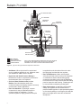
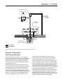
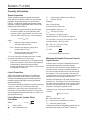
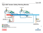
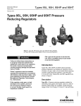
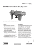
Bulletin 71.2:92C
November 2009
Type 92C Self-Powered Control Valve
W3111-2
W3110
Type 92C Pressure-Loaded Control Valve
Type 92C Self-Powered Control Valve with Type 6392 Pilot
Figure 1. Type 92C Pressure Regulator
Introduction
The Type 92C regulator (Figure 1) is an economical
cast iron, steel, or stainless steel pressure-reducing
regulator used in steam, liquid or hot air service. This
regulator is available with a Type 6392 pilot for use
as a pilot-operated regulator or without a pilot for use
as a pressure-loaded regulator. The pilot-operated
version uses inlet pressure as the operating medium;
no separate air supply is required. The pressureloaded version is used where remote adjustment of the
regulator pressure setting is required; a Type 67, 1301F
regulator, or a 670 panel loader can be used as the
loading regulator.
Features
• Shutoff Performance—The machine-lapped, flat-face seating surfaces featured in the
Type 92C regulator and Type 6392 pilot design
have been time-proven to minimize seat leakage when downstream demand is zero and the regulator is shutoff.
D100137X012
A Type 6492HM or 6492HTM safety override pilot is
also available for the Type 92C. The Type 6392 pilot
is used in a series installation with the Type 6492HM
or 6492HTM safety override pilot installed on the
upstream valve. The Type 6492HM or 6492HTM
safety override pilot senses pressure downstream
of the second valve, and prevents pressure from
rising above safe operating pressure in the event the
downstream valve fails. This system is approved by
ASME B31.1-1989, 122.14.2.A, and can replace an
ASME safety valve when vent piping is not practical
and upstream pressure does not exceed 400 psig
(27,6 bar). Local codes and standards may require
approval by an appropriate authority prior to installation.
www.fisherregulators.com
Bulletin 71.2:92C
Specifications
Body Sizes and End Connection Styles
Cast Iron: 1/2, 3/4, 1 NPT
Steel or Stainless Steel: NPS 1/2, 3/4, or 1
(DN 15, 20, or 25) NPT; CL150 RF; CL300 RF;
or PN 16/25/40
Maximum Allowable Inlet and
Pilot Supply Pressures(1)
Cast Iron Construction: 250 psig (17,2 bar)
Steel and Stainless steel Construction:
300 psig (20,7 bar)
Regulator Pressure Drops(1)
Minimum: 15 psi (1,0 bar)
Maximum Operating: Do not exceed the
pressure drops in the capacity tables
Maximum Emergency(2)
Cast Iron Construction: 250 psi (17,2 bar)
Steel and Stainless steel Construction:
300 psi (20,7 bar)
Outlet Pressure Range
See Table 1
Maximum Outlet Pressures(2)
Maximum Operating Outlet Pressure:
150 psig (10,3 bar)
Maximum Emergency Outlet (Casing) Pressure
Cast Iron Construction: 250 psig (17,2 bar)
Steel and Stainless steel Construction: 300 psig (20,7 bar)
Loading Pressure For Pressure-Loaded Regulator(2)
See Figure 5 to determine loading pressure. Maximum allowable loading pressure(2) is 250 psig (17,2 bar) for cast iron construction and 300 psig (20,7 bar) for steel and stainless steel construction; the maximum allowable diaphragm differential pressure of 150 psi (10,3 bar) for cast iron,
steel, and stainless steel constructions must not be exceeded
Orifice Sizes
NPS 1/2 (DN 15) Main Valve: 9/16-inch (14 mm)
NPS 3/4 and 1 (DN 20 and 25) Main Valves:
3/4-inch (19 mm) is standard; 9/16-inch
(14 mm) is optional
Flow Capacity
See Capacity Information section
Flow and Sizing Coefficients
See Tables 2 and 3
Proportional Band
10%
Construction Materials
Type 92C Self-Powered Control Valve
Main Valve Body and Diaphragm Flange: Cast iron, Steel, or Stainless steel
Orifice and Valve Stem: Heat-treated 416
Stainless steel
Main Valve Plug (Metal Seat Construction):
Heat-treated 416 Stainless steel
Main Valve Disk and Disk Holder (Elastomeric Seat Construction) Disk: Ethylenepropylene (EPR)
Disk Holder: Heat-treated 416 Stainless steel
Main Valve Diaphragms and Valve Plug Springs: Stainless steel
Stem Guides: Heat-treated 416 Stainless steel
Main Valve Plug Guides
Cast Iron Construction: Brass
Steel Construction: Heat-treated 416 Stainless steel
Type 6392 Pilot
Pilot Body and Pilot Spring Case: Cast iron, Steel, or Stainless steel
Pilot Valve Plug (Metal Seat Construction):
Heat-treated 416 Stainless steel
Pilot Valve Disk and Disk Holder (Elastomeric Seat Construction) Disk: Ethylenepropylene (EPR)
Disk Holder: Heat-treated 416 Stainless steel
Pilot Diaphragms: Stainless steel
Pilot Stem Guides: Heat-treated 416 Stainless steel
Pilot Valve Plug Guides
Cast Iron Construction: Brass
Steel Construction: Heat-treated 416 Stainless steel
Pilot Control Spring: 416 or 17-7PH Stainless steel
Pilot Inlet Screen: Stainless steel
Loading Pressure Tubing: Copper (used for pilot operated regulator only) or Stainless steel
Pilot Fittings: Brass or Stainless steel
Pilot Supply Line: Steel pipe nipple
Types 6492HM and 6492HTM Safety
Override Pilots
Pilot Valve Body: WCC steel and CF8M
Stainless steel
Valve Guide
For Steel Body: 416 Stainless steel
For Stainless steel Body: 316 Stainless steel
Valve Spring: 302 Stainless steel
Orifice
For Steel Body: 416 Stainless steel
For Stainless steel Body: 316 Stainless steel
Valve Stem
For Steel Body: 410/416 Stainless steel
For Stainless steel Body: 316 Stainless steel
- continued 2
Bulletin 71.2:92C
Specifications (continued)
Pressure Registration
With Pilot: External
Without Pilot: Internal
Diaphragm: 302 Stainless steel
Lower Spring Seat
For Type 6492HM: Aluminum
For Type 6492HTM: Steel or Stainless steel
Spring
For Type 6492HM: Steel
For Type 6492HTM: Stainless steel
Upper Spring Seat: Steel
Spring Case: Steel or Stainless steel
Pipe Plug: Steel or Stainless steel
Downstream Control Line Connection
1/4 NPT (internal) in pilot body (downstream control line not required for pressure-loaded regulator)
Loading Pressure Connection
1/4 NPT (internal) in main valve diaphragm flange (this connection is factory-piped to the pilot on pilot-operated regulator)
Maximum Material Temperature Capabilities(2)
Metal Diaphragm and Seat
Cast Iron Construction: -40° to 406°F (-40° to 208°C)
Steel Construction: -20° to 500°F (-29° to 260°C)
Ethylenepropylene (EPR) Seat: -40° to 275°F
(-40° to 135°C)
Optional High-Temperature Steel or Stainless Steel Body: 650°F (343°C)
Pilot Spring Case Vent
3/32-inch (2,4 mm) drilled hole
1. Also see Installation section
2. Pressure/temperature limits in this Bulletin and any application codes must not be exceeded.
Approximate Weights
Cast iron, Steel, or Stainless steel Body
with Pilot: 20 pounds (9 kg)
Cast iron, Steel, or Stainless steel Body
without Pilot: 16 pounds (7 kg)
Table 1. Outlet Pressure Ranges
outlet pressure range
psig, (bar)
spring usage
spring part number
and color
5 to 70 (0,34 to 4,8)
Standard use up to 500°F (260°C)
High-Pressure and/or High
Temperature over 500°F (260°C)
spring wire
diameter,
inches (mm)
spring free
length,
inches (mm)
1E392627012 Green
0.170 (4,3)
2.00 (50,8)
20 to 150 (1,4 to 10,3)
1E392727142 Red
0.207 (5,3)
1.94 (49,3)
15 to 100 (1,0 to 6,9)
14B9941X012 Unpainted
0.192 (4,9)
80 to 250 (5,5 to 17,2)
14B9940X012 Unpainted
0.282 (7,2)
1.96 (49,8)
Table 2. Flow Coefficients(1)
wide-open for relief sizing
orifice size,
inches (mm)
cg
Cs
cv
9/16 (14)
170
8.5
5
3/4 (19)
240
12
7.1
c1
km
34
0.67
1. Cv = Cs x 20 ÷ C1
Table 3. IEC Sizing Coefficients
body size,
NPS (DN)
1/2 (15)
3/4 or 1 (20 or 25)
orifice size, inches (mm)
9/16 (14)
xT
0.73
FD
0.38
0.44
3/4 (19)
Fl
0.82
xT
FD
Fl
---0.73
0.38
0.82
3
Bulletin 71.2:92C
PILOT REGULATOR SPRING
PILOT DIAPHRAGM
PILOT
SUPPLY
DOWNSTREAM
BLEED HOLE
PILOT
VALVE
PLUG
PILOT
VALVE
SPRING
DOWNTREAM
CONTROL LINE
MAIN VALVE
DIAPHARGM
PITOT TUBE
MAIN VALVE PLUG
MAIN VALVE SPRING
A6618
inlet pressure
outlet pressure
atmospheric pressure
loading pressure
Note: Pilot is shown here above the main valve body for illustration
purposes only. See figures 1 and 8 for actual pilot position and
appearance of pilot supply line and loading-pressure tubing.
Figure 2. Type 92C with Type 6392 Pilot Operational Schematic
• Soft Seats—When tight shutoff is required and service conditions permit their use, elastomer seats are available for ASME Class VI shutoff.
• Equal Inlet and Outlet Pressure Ratings—
Eliminate the need for overpressure protection for the downstream side of the regulator.
• Choice of Steel, Stainless steel, or Iron Bodies—Steel and stainless steel valve
construction helps resist piping stresses commonly encountered in steam applications.
• Ease of Installation—Lightweight, compact construction is easy to install and requires a
minimum space for installation. For pilot-
operated regulators, supply pressure to the pilot 4
is supplied from the inlet side of the main valve
through piping furnished with the regulator.
• Ease of Maintenance—Main valve and pilot valve plug and seat can be removed for inspection or maintenance without disassembling piping connections and without removing the diaphragm. Pilot-inlet screen is easily removed with the seating parts for inspection and cleaning. Diaphragms can be removed without disturbing seating parts.
• Ease of Conversion—If application requirements change, the regulator can be converted from a pressure-loaded regulator to a pilot-operated regulator or vice-versa by adding or removing the pilot and pilot piping; no changes to the main valve construction
are required.
Bulletin 71.2:92C
bleed restriction
loading regulator
optional
piping
for steam
loading
main valve
diaphragm
pitot tube
MAIN VALVE PLUG
36A1546-B
A2946
MAIN VALVE SPRING
inlet pressure
outlet pressure
loading pressure
Figure 3. Type 92C Pressure-Loaded Control Valve Operational Schematic
Principle of Operation
Pilot-Operated Regulator
Refer to the schematic in Figure 2. Pilot supply
pressure is piped from the inlet side of the main valve
to the pilot inlet connection. Downstream pressure
registers under the main valve diaphragm through
the pitot tube under the pilot diaphragm through the
downstream control line.
When downstream pressure decreases to a value
below the setting of the pilot regulator spring, the pilot
spring forces the pilot valve plug open, increasing
the loading pressure on the top of the main valve
diaphragm. The increased loading pressure on top of
the main valve diaphragm and decreased downstream
pressure under the main valve diaphragm force the
main valve diaphragm and stem downward. This
opens the main valve plug, and increases flow to
the downstream system thus restoring downstream
pressure to the setting of the pilot regulator spring.
When downstream pressure increases, it registers under
the pilot diaphragm and overcomes the force of the pilot
spring. This allows the pilot valve spring to close the pilot
valve plug and causes excess loading pressure to bleed
to the downstream system through the pilot bleed hole. At
the same time, increased downstream pressure registers
under the main valve diaphragm. The decreased
loading pressure on top of the main valve diaphragm and
increased downstream pressure under the main valve
diaphragm force the main valve diaphragm upward. This
allows the main valve plug spring close to the main valve
plug, reducing flow to the downstream system.
5
Bulletin 71.2:92C
type 6492HM safety
override pilot
type 6392 pilot
type 6392 pilot
type 92c main valve
type 92C main valve
EO557
inlet pressure
outlet pressure
atmospheric pressure
loading pressure
intermediate pressure
Figure 4. Type 92C with Type 6492HM Safety Override Pilot Operational Schematic
Table 4. Type 6492 Safety Override Pilot Spring Ranges and Minimum Differential Pressures
type
6492hm
6492htm
spring color
minimum pressure at which
monitoring pilot can be set, psig (bar)
10 to 30 (0,69 to 2,1)
Yellow
5 (0,34) over normal distribution pressure
25 to 75 (1,7 to 5,2)
Green
70 to 150 (4,8 to 10,3)
Red
spring ranges, psig (bar)
80 to 250 (5,5 to 17,2)
15 to 100 (1,0 to 6,9)
10 (0,69) over normal distribution pressure
Unpainted
----
Pressure-Loaded Regulator
Safety Override Pilot
Refer to the schematic in Figure 3. With a pressureloaded regulator, a remote, adjustable loading regulator
provides loading pressure to the top of the main valve
diaphragm. Downstream pressure registers under the
main valve diaphragm through the pilot tube.
Refer to the schematic in Figure 4. Once placed in
operation, the upstream Type 6392 pilot senses the
intermediate pressure between both valves, and the
Type 6492HM or 6492HTM pilot senses downstream
pressure of the second valve. As demand for flow
increases, intermediate pressure will fall causing the
Type 6392 pilot to open. As the Type 6392 pilot valve
opens, loading pressure to the main valve increases,
opening the main valve.
When downstream pressure decreases, it registers
under the diaphragm and allows the stem and plug to
move downward, thereby opening the valve to increase
downstream pressure.
When downstream pressure increases, it registers
under the diaphragm and forces the stem and plug
to move upward. The upward force of the spring
causes the valve to close, which decreases flow to
the downstream system thus decreasing downstream
pressure. In hot air service, supply air above the
diaphragm becomes compressed and is vented to the
atmosphere. If a steam supply is used, the steam is
vented downstream.
6
The Type 6492HM or 6492HTM safety override
pilot remains open because its setpoint is above the
setpoint of the downstream valve. In the unlikely event
that the downstream valve fails open, downstream
pressure will rise above the downstream valve’s
setpoint. This pressure is sensed by the
Type 6492HM or 6492HTM safety override pilot. As
downstream pressure increases the safety override
pilot closes, reducing loading pressure to the main
Bulletin 71.2:92C
pressure drop across valve (bar)
2,00
4,00
10,0
8,00
6,00
12,0
3/4-inch
(19 mm)
orifice
size
diaphragm differential (PSI)
15
1,00
10
0,50
9/16-inch
(14 mm)
orifice
size
5
0
100
50
150
diaphragm differential (bar)
20
200
pressure drop across valve (PSI)
26A3808-A
A2508-2
note:
to determine required loading pressure, add the
diaphragm differential pressure to the desired
outlet pressure setting
Figure 5. Diaphragm Differential Pressure for Pressure-Loaded Regulator
valve, which positions the main valve to maintain
downstream pressure as specified per ASME Boiler
and Pressure Vessel Code, Section VIII.
In the event that the upstream valve fails, the
downstream regulator will prevent downstream
pressure from rising above safe operating levels.
It is recommended to install some type of warning system,
such as a sentinel relief valve, to warn the operator that a
valve has failed in the system. This will prevent prolonged
operation with one valve, which could cause valve
trim wear and noise associated with operation at high
differential pressures.
When operating in most steam systems, valve setpoints
should be in strict accordance to ASME Boiler and
Pressure Vessel Code, Section VIII. The Type 6492HM
or 6492HTM safety override pilot should be set at
10 psig (0,69 bar) or 10% above maximum downstream
operating pressure of the second valve, whichever
pressure is greater. For example, most HVAC systems
operate at 15 psig (1,0 bar), so the safety override pilot
should be set no higher than 25 psig (1,7 bar).
Installation
The Type 92C regulator should be installed and used
in accordance with federal, state, and local codes and
regulations. Downstream overpressure protection should
be provided by the user if the maximum inlet pressure
exceeds the downstream pressure of the system. The
pressure and temperature limitations in the Specifications
section must be observed.
The Type 92C regulator may be installed in any
orientation. However, on steam service the regulator
should not be installed at the bottom of a tall vertical
pipeline where condensate could collect and create a
pressure head affecting regular performance.
A downstream control line is required for pilot-operated
regulators; the control line is not furnished with the
regulator. An adjustable loading pressure regulator
and loading pressure piping are required for pressureloaded regulators.
7
Bulletin 71.2:92C
Capacity Information
Steam Capacities
Typical regulating capacities in pounds of saturated
steam per hour are shown in Table 5 for pilot-operated
regulators. A typical performance curve is shown in
Figure 6. To determine capacities for pressure-loaded
regulators, multiply the appropriate Table 5 value by the
capacity factor listed in Table 7.
Cv = Valve sizing coefficient (see Table 6)
G = Specific Gravity
1. If the steam is saturated and the pressure drop across the regulator is critical (absolute outlet pressure equal to approximately one-half or less of the absolute inlet pressure), use the equation:
Q = (P1abs) (Cs)
where,
Glycol (Specific Gravity) = 1.11
Example,
NPS 1 (DN 25) body
3/4-inch (19 mm) orifice size
= Maximum flow capacity, pounds of saturated steam per hour
P1abs = Absolute inlet pressure (gauge inlet
pressure plus 14.7 psi)
Q
= Wide-open steam sizing coefficient
(see Specifications section)
Cs
To convert capacity to kilograms per hours, multiply
the capacity pounds per hour by 0.4536.
2. If the steam is superheated or if the pressure drop across the regulator is lower than critical (absolute outlet pressure greater than approximately
one-half the absolute inlet pressure), use the sizing
nomographs in Catalog 10.
Liquid Capacities
Table 6 gives regulating capacities in U.S. gallons per
minute of water and in cubic meters per hour of water.
To determine capacities for pressure-loaded regulators,
multiply the approximate Table 6 value by the capacity
factor listed in Table 7.
To determine regulating capacities at pressure settings
not given in Table 6, or to determine wide-open
capacities for relief sizing at any inlet pressure, use
the Catalog 10 liquid sizing procedures in conjunction
with the appropriate liquid coefficients (Cv and Km, see
Specifications section).
Liquid Sizing for Liquids Other
than Water
Where,
Q P
8
Q = Cv
= Flow in GPM
= Valve differential in psi
P
G
Pinlet = 150 psig (10,3 bar)
Pout (setpoint) = 50 psig (3,4 bar)
Capacity based on 10% Droop from setpoint
Pout at full flow = 50 psi (3,4 bar) setpoint - 5 psi
(0,35 bar) Droop = 45 psi (3,1 bar)
P = 150 - 45 = 105 psi (7,2 bar)
Cv = 6.89 from Table 6
Q = 6.89
105
1.11
= 67.0 GPM (253,60 l/min) Glycol
Maximum Allowable Pressure Drop for
Liquid Service
Pressure drops in excess of allowable will result in
choked flow and possible cavitation damage.
Choked flow is the formation of vapor bubbles in the
liquid flow stream causing a crowding condition at
the vena contracta which tends to limit flow through
the regulator. The vena contracta is the minimum
cross-sectional area of the flow stream occurring just
downstream of the actual physical restriction.
Cavitation and flashing are physical changes in the
process fluid. The change is from the liquid state to
the vapor state and results from the increase in fluid
velocity at or just downstream of the greatest flow
restriction, normally the regulator orifice.
To determine the maximum allowable pressure drop
for water:
P(allow) = Km (P1)
Where,
P = Valve differential — psi
Km = Valve recovery coefficient from Table 7
P1 = Valve inlet pressure psia
To determine maximum allowable pressure drop for
fluids other than water, see Fisher® Catalog 10.
Bulletin 71.2:92C
Table 5. Steam Flow Capacities for Pilot-Operated Type 92C Regulator(1) (Based on 10 Percent Proportional Band)
outlet
pressure
setting
Psig
5(3)
10(3)
15(3)
20(3)
30(3)
40(3)
50
60
80
inlet
pressure
capacity (pounds per hour(2) (Kg/h) of saturated steam)
NPS 1/2 (DN 15)
Main Valve
9/16-Inch
(14 mm)
Orifice Size
NPS 3/4 (DN 20)
Main Valve
Standard
3/4-Inch (19 mm)
Orifice Size
NPS 1 (DN 25)
Main Valve
Optional
9/16-Inch
(14 mm)
Orifice Size
Standard
3/4-Inch (19 mm)
Orifice Size
Optional
9/16-Inch
(14 mm)
Orifice Size
Bar
Psig
Bar
0,34(3)
20
25
30
50
1,4
1,7
2,1
3,4
170
200
240
250
75
100
150
5,2
6,9
10,3
370 (168)
370 (168)
400 (181)
590 (268)
710 (322)
740 (336)
450 (204)
500 (227)
560 (254)
880 (399)
980 (445)
1000 (454)
500 (227)
600 (272)
660 (299)
25
30
50
1,7
2,1
3,4
210 (95,3)
240 (109)
360 (163)
300 (136)
390 (177)
600 (272)
220 (99,8)
280 (127)
410 (186)
360 (163)
430 (195)
680 (308)
250 (113)
300 (136)
450 (204)
75
100
150
5,2
6,9
10,3
400 (181)
550 (249)
600 (272)
680 (308)
830 (376)
880 (399)
500 (227)
680 (308)
710 (322)
900 (408)
1100 (499)
1150 (522)
580 (263)
770 (349)
800 (363)
1,0(3)
30
50
75
100
150
2,1
3,4
5,2
6,9
10,3
220
380
480
620
650
(99,8)
(172)
(218)
(281)
(295)
350
610
800
960
1100
(159)
(277)
(363)
(435)
(499)
260
430
570
750
780
(118)
(195)
(259)
(340)
(354)
410
720
930
1250
1300
(186)
(327)
(422)
(567)
(590)
280
480
620
830
880
(127)
(218)
(281)
(376)
(399)
1,4(3)
35
50
75
100
150
200
2,4
3,4
5,2
6,9
10,3
13,8
240
380
550
700
800
1000
(109)
(172)
(249)
(318)
(363)
(454)
370
630
870
1150
1200
(168)
(286)
(395)
(522)
(544)
270
430
630
800
900
1150
(122)
(195)
(286)
(363)
(408)
(522)
420
720
950
1300
1400
(191)
(327)
(431)
(590)
(635)
290
480
670
900
1000
1300
(132)
(218)
(304)
(408)
(454)
(590)
2,1(3)
50
75
100
150
200
3,4
5,2
6,9
10,3
13,8
330
550
700
950
1000
(150)
(249)
(318)
(431)
(454)
550
880
1150
1400
400
630
800
1100
1200
(181)
(286)
(363)
(499)
(544)
570
950
1300
1600
450
670
900
1200
1400
(204)
(304)
(408)
(544)
(635)
55
60
75
3,8
4,1
5,2
100
150
200
250
6,9
10,3
13,8
17,2
700
1000
1100
1300
(318)
(454)
(499)
(590)
3,4
65
75
100
150
200
250(4)
4,5
5,2
6,9
10,3
13,8
17,2
370
480
700
1000
1200
1400
(168)
(218)
(318)
(454)
(544)
(635)
4,1
75
80
100
150
200
250(4)
5,2
5,5
6,9
10,3
13,8
17,2
360
430
640
1000
1200
1500
(163)
(195)
(290)
(454)
(544)
(680)
630
700
1000
1500
2000
5,5
100
150
200
250
6,9
10,3
13,8
17,2
500
1000
1300
1500
(227)
(454)
(590)
(680)
900 (408)
1500 (680)
2000 (907)
0,69(3)
2,8(3)
(77,1)
(90,7)
(109)
(113)
330 (150)
390 (177)
480 (218)
230
280
340
440
(104)
(127)
(154)
(200)
---(249)
(399)
(522)
(635)
---560 (254)
610 (277)
870 (395)
1150 (522)
1400 (635)
------600 (272)
740 (336)
1100 (499)
1500 (680)
1800 (816)
---(286)
(318)
(454)
(680)
(907)
----
----
180
210
270
310
(81,7)
(95,3)
(122)
(141)
400 (181)
450 (204)
600 (272)
300
380
410
680
(136)
(172)
(186)
(308)
---(259)
(431)
(590)
(726)
---580 (263)
670 (304)
930 (422)
800
1150
1300
1550
(363)
(522)
(590)
(703)
1300 (590)
1700 (771)
440
550
800
1200
1350
1700
(200)
(249)
(363)
(544)
(612)
(771)
650
820
1250
1900
2300
400
500
700
1200
1500
1800
(181)
(227)
(318)
(544)
(680)
(816)
740
850
1200
1900
2600
620
1200
1500
1800
(281)
(544)
(680)
(816)
950 (431)
1800 (816)
2500 (1134)
------(295)
(372)
(567)
(862)
(1043)
---(336)
(386)
(544)
(862)
(1179)
----
----
200
230
280
410
(90,7)
(104)
(127)
(186)
430 (195)
480 (218)
660 (299)
900
1250
1500
1700
(408)
(567)
(680)
(771)
470
600
850
1300
1600
1850
(213)
(272)
(386)
(590)
(726)
(839)
450
550
800
1300
1700
2000
(204)
(249)
(363)
(590)
(771)
(907)
730
1200
1700
2000
(331)
(544)
(771)
(907)
1. To determine capacities for pressure-loaded Type 92C regulators, multiply the printed value by the appropriate value shown in Table 7.
2. To convert capacity to kg/hr, multiply by 0.4536.
3. Capacities for outlet pressure settings lower than 50 psig (3,4 bar) are based on a 2 to 1 ratio of outlet pipe size to main valve body size.
4. 20 to 150 psig (1,4 to 10,3 bar) pilot control spring only (red spring 1E392727142).
- continued -
9
Bulletin 71.2:92C
Table 5. Steam Flow Capacities for Pilot-Operated Type 92C Regulator(1) (Based on 10 Percent Proportional Band) (continued)
outlet
pressure
setting
Psig
capacity (pounds per hour(2) (Kg/h) of saturated steam)
inlet
pressure
NPS 1/2 (DN 15)
Main Valve
9/16-Inch (14 mm)
Orifice Size
NPS 3/4 (DN 20)
Main Valve
Standard
3/4-Inch (19 mm)
Orifice Size
Bar
Psig
Bar
6,9
125
150
200
250
300
8,6
10,3
13,8
17,2
20,7
600
850
1300
1600
2000
(272)
(386)
(590)
(726)
(907)
1000
1500
2200
2400
125
8,6
150
200
250
300
10,3
13,8
17,2
20,7
700
1200
1600
2000
(318)
(544)
(726)
(907)
1000
2100
2400
3000
150
10,3
175
200
250
300
12,1
13,8
17,2
20,7
800
1000
1500
2000
(363)
(454)
(680)
(907)
1100
2000
2300
3000
100
(454)
(680)
(998)
(1089)
NPS 1 (DN 25)
Main Valve
Optional
9/16-Inch (14 mm)
Orifice Size
Standard
3/4-Inch (19 mm)
Orifice Size
750
1000
1600
2000
2400
(340)
(454)
(726)
(907)
(1089)
1100
1600
2400
3000
(454)
(953)
(1089)
(1361)
800
1400
2000
2400
(363)
(635)
(907)
(1089)
1200
2200
3000
3600
(499)
(907)
(1043)
(1361)
900
1100
1800
2400
(408)
(499)
(816)
(1089)
1400
2000
2800
3600
----
Optional
9/16-Inch (14 mm)
Orifice Size
(499)
(726)
(1089)
(1361)
850
1200
1700
2100
2500
(386)
(544)
(771)
(953)
(1134)
(544)
(998)
(1361)
(1633)
850
1500
2100
2500
(386)
(680)
(953)
(1134)
(635)
(907)
(1270)
(1633)
950
1300
1900
2500
(431)
(590)
(862)
(1134)
----
1. To determine capacities for pressure-loaded Type 92C regulators, multiply the printed value by the appropriate value shown in Table 7.
2. To convert capacity to kg/hr, multiply by 0.4536.
Table 6. Water Flow Capacities and Regulating Cv Values for Type 92C Regulator(1) (Based on 10 Percent Proportional Band)
outlet
pressure
setting
inlet
pressure
Psig
Bar
Psig
Bar
gpm
m3/h
Cv
gpm
m3/h
Cv
gpm
m3/h
Cv
gpm
m3/h
Cv
gpm
m3/h
Cv
0,34
20
25
30
50
1,4
1,7
2,1
3,4
12
14
16
15
2,73
3,18
3,63
3,41
3.13
3.11
3.26
2.28
17
20
23
27
3,86
4,54
5,22
6,13
4.23
4.36
4.61
4.02
13
15
19
19
2,95
3,40
4,32
4,32
3.31
3.27
3.66
2.83
22
27
28
42
5,00
6,13
6,36
9,54
5.62
5.91
5.56
6.21
14
16
19
25
3,18
3,63
4,32
5,68
3.68
3.58
3.80
3.75
75
100
150
5,2
6,9
10,3
20
19
17
4,54
4,32
3,86
2.43
1.90
1.43
32
36
32
7,27
8,18
7,27
3.87
3.64
2.64
25
25
24
5,68
5,68
5,45
2.95
2.56
2.00
48
49
43
10,90
11,14
9,77
5.77
5.03
3.57
28
30
28
6,36
6,81
6,36
3.28
3.08
2.36
25
30
50
1,7
2,1
3,4
14
16
21
3,18
3,63
4,77
3.47
3.39
3.32
20
25
35
4,54
5,68
7,95
4.95
5.50
5.54
15
18
24
3,40
4,10
5,45
3.63
3.95
3.79
24
28
40
5,45
6,36
9,10
5.94
6.07
6.28
17
19
27
3,86
4,32
6,13
4.13
4.23
4.15
75
100
150
5,2
6,9
10,3
21
27
25
4,77
6,13
5,68
2.63
2.82
2.14
36
41
37
8,18
9,31
8,40
4.47
4.26
3.14
27
33
30
6,13
7,50
6,81
3.29
3.49
2.54
48
54
49
11,00
12,27
11,14
5.91
5.64
4.11
31
38
34
7,04
8,63
7,72
3.81
3.95
2.86
1,0
30
50
75
100
150
2,1
3,4
5,2
6,9
10,3
13
22
25
30
27
2,95
5,00
5,68
6,81
6,13
3.31
3.57
3.17
3.18
2.32
21
35
41
46
46
4,77
7,95
9,31
10,50
10,50
5.26
5.73
5.28
4.93
3.93
16
24
30
36
33
3,63
5,45
6,81
8,18
7,50
3.91
4.04
3.76
3.85
2.79
25
41
48
60
54
5,68
9,31
10,91
13,64
12,27
6.17
6.76
6.14
6.42
4.64
17
27
32
40
37
3,86
6,13
7,27
9,10
8,40
4.21
4.51
4.09
4.26
3.14
1,4
35
50
75
100
150
200
2,4
3,4
5,2
6,9
10,3
13,8
14
21
28
33
33
37
3,18
4,77
6,36
7,50
7,50
8,40
3.32
3.66
3.66
3.60
2.86
2.74
21
34
44
54
49
----
4,77
7,72
10,00
12,27
11,14
----
5.12
6.07
5.79
5.92
4.29
----
15
23
32
37
37
43
3,41
5,22
7,27
8,40
8,40
9,77
3.74
4.14
4.19
4.12
3.21
3.15
24
39
48
61
57
----
5,45
8,86
10,91
13,87
12,96
----
5.81
6.94
6.32
6.69
5.00
----
17
26
34
42
41
48
3,86
5,91
7,72
9,54
9,31
10,91
4.01
4.62
4.46
4.63
3.57
3.56
5(2)
10(2)
15(2)
20(2)
0,69
NPS 1/2 (DN 15)
main valve
9/16-Inch (14 mm)
Orifice Size
NPS 3/4 (DN 20)
main valve
Standard
3/4-Inch (19,3 mm)
Orifice Size
NPS 1 (DN 25)
main valve
Optional
9/16-Inch (14 mm)
Orifice Size
Standard
3/4-Inch (19,1mm)
Orifice Size
1. To determine capacities for pressure-loaded Type 92C regulators, multiply the printed value by the appropriate value shown Table 7.
2. Capacities for outlet pressure settings lower than 50 psig (3,4 bar) are based on a 2 to 1 ratio of outlet pipe size to main valve body size.
- continued -
10
Optional
9/16-Inch (14 mm)
Orifice Size
Bulletin 71.2:92C
Table 6. Water Flow Capacities and Regulating Cv Values for Type 92C Regulator(1) (Based on 10 Percent Proportional Band) (continued)
outlet
pressure
setting
Psig
inlet
pressure
NPS 1/2 (DN 15)
main valve
9/16-Inch (14 mm)
Orifice Size
NPS 3/4 (DN 20)
main valve
Standard
3/4-Inch (19 mm)
Orifice Size
NPS 1 (DN 25)
main valve
Optional
9/16-Inch (14 mm)
Orifice Size
Standard
3/4-Inch (19 mm)
Orifice Size
Optional
9/16-Inch (14 mm)
Orifice Size
Bar
Psig
Bar
gpm
m3/h
Cv
gpm
m3/h
Cv
gpm
m3/h
Cv
gpm
m3/h
Cv
gpm
m3/h
Cv
30(2)
2,1
50
75
100
150
200
3,4
5,2
6,9
10,3
13,8
17
26
31
38
36
3,86
6,00
7,04
8,63
8,18
3.47
3.78
3.66
3.40
2.74
28
42
51
56
----
6,36
9,54
11,59
12,73
----
5.78
6.02
5.99
5.01
----
20
30
36
44
43
4,54
6,81
8,18
10,00
9,77
4.20
4.31
4.16
3.93
3.29
29
45
58
63
----
6,59
10,23
13,18
14,32
----
5.99
6.50
6.77
5.72
----
23
32
40
48
50
5,22
7,27
9,09
10,91
11,36
4.73
4.58
4.68
4.29
3.84
40(2)
2,8
55
60
75
3,8
4,1
5,2
15
18
21
3,41
4,09
4,77
3.51
3.66
3.44
26
28
39
5,91
6,36
8,86
5.96
6.73
6.23
19
21
27
4,32
4,77
6,13
4.26
4.23
4.30
27
31
42
6,13
7,04
9,54
6.17
6.29
6.66
20
22
30
4,54
5,00
6,81
4.58
4.51
4.73
2,8
100
150
200
250
6,9
10,3
13,8
17,2
30
38
39
42
6,81
8,63
8,86
9,54
3.72
3.59
3.02
2.89
49
54
-------
11,14
12,27
-------
6.10
5.03
-------
34
44
46
50
7,72
10,00
10,46
11,36
4.25
4.13
3.58
3.44
55
65
-------
12,50
14,77
-------
6.90
6.11
-------
38
48
53
55
8,63
10,91
12,05
12,50
4.78
4.49
4.11
3.78
3,4
65
75
100
150
200
250(3)
4,5
5,2
6,9
10,3
13,8
17,2
16
20
28
37
41
45
3,63
4,54
6,36
8,40
9,31
10,23
3.55
3.71
3.83
3.62
3.30
3.11
26
31
45
56
62
----
5,91
7,04
10,23
12,73
14,09
----
5.75
5.71
6.02
5.44
4.95
----
19
23
32
45
46
54
4,32
5,22
7,27
10,23
10,46
12,27
4.22
4.25
4.38
4.35
3.71
3.78
28
35
51
71
79
----
6,36
7,95
11,59
16,14
17,96
----
6.23
6.33
6.84
6.89
6.32
----
20
25
34
48
55
59
4,54
5,68
7,72
10,91
12,50
13,41
4.51
4.63
4.65
4.71
4.40
4.11
60
4,1
75
80
100
150
200
250(3)
5,2
5,5
6,9
10,3
13,8
17,2
14
17
25
36
40
47
3,18
3,86
5,68
8,18
9,09
10,68
3.15
3.36
3.66
3.67
3.31
3.34
25
28
39
54
67
----
5,68
6,36
8,86
12,27
15,23
----
5.51
5.47
5.72
5.50
5.52
----
16
20
27
43
50
56
3,63
4,54
6,13
9,77
11,36
12,73
3.50
3.91
4.01
4.40
4.14
4.01
30
34
47
68
87
----
6,81
7,72
10,68
15,46
19,78
----
6.47
6.64
6.87
6.97
7.18
----
18
22
31
47
57
62
4,10
5,00
7,04
10,68
12,96
14,09
3.93
4.30
4.58
4.77
4.69
4.45
80
5,5
100
150
200
250
6,9
10,3
13,8
17,2
18
34
41
45
4,09
7,72
9,31
10,23
3.36
3.82
3.65
3.36
32
51
63
----
7,27
11,59
14,32
----
6.06
5.73
5.61
----
22
41
48
54
5,00
9,31
10,91
12,27
4.17
4.59
4.21
4.04
36
61
79
----
8,18
13,86
17,96
----
6.39
6.88
7.01
----
26
41
54
60
6,00
9,31
12,27
13,64
4.91
4.59
4.77
4.48
100
6,9
125
150
200
250
300
8,6
10,3
13,8
17,2
20,7
19
27
39
46
55
4,32
6,13
8,86
10,46
12,50
3.28
3.48
3.75
3.63
3.77
32
48
67
69
----
7,27
10,91
15,23
15,68
----
5.47
6.15
6.34
5.45
----
24
32
48
57
66
5,45
7,27
10,91
12,96
15,00
4.10
4.10
4.61
4.54
4.53
38
51
73
86
----
8,64
11,59
16,59
19,55
----
6.02
6.56
6.92
6.81
----
28
38
51
60
68
6,36
8,63
11,59
13,64
15,46
4.65
4.92
4.90
4.77
4.72
125
8,6
150
200
250
300
10,3
13,8
17,2
20,7
21
34
44
52
4,77
7,72
10,00
11,82
3.37
3.65
3.73
3.83
29
60
66
79
6,59
13,64
15,00
17,96
4.81
6.39
5.59
5.74
24
40
55
63
5,45
9,10
12,50
14,32
3.85
4.26
4.66
4.59
35
63
82
94
7,95
14,32
18,64
21,37
5.77
6.70
6.99
6.89
25
43
57
66
5,68
9,77
12,96
15,00
4.09
4.57
4.90
4.79
150
10,3
175
200
250
300
12,1
13,8
17,2
20,7
22
27
39
50
5,00
6,13
8,86
11,36
3.44
3.33
3.64
3.91
30
54
60
75
6,81
12,27
13,64
17,05
4.73
6.67
5.58
5.87
24
30
47
60
5,45
6,81
10,68
13,64
3.87
3.67
4.37
4.70
38
54
73
91
8,63
12,27
16,59
20,68
6.02
6.67
6.80
7.05
26
35
49
63
6,00
7,95
11,14
14,32
4.08
4.33
4.61
4.89
40(2)
50
1. To determine capacities for pressure-loaded Type 92C regulators, multiply the printed value by the appropriate value shown Table 7.
2. Capacities for outlet pressure settings lower than 50 psig (3,4 bar) are based on a 2 to 1 ratio of outlet pipe size to main valve body size.
3. 20 to 150 psig (1,4 to 10,3 bar) pilot control spring only (red spring 1E392727142).
11
Bulletin 71.2:92C
190
13,0
typical performance
NPS 1 (DN 25) type 92C
3/4-inch (19 mm)
orifice size
outlet pressure (Psi)
170
12,0
160
11,0
150
10,0
140
130
120
9,00
250 psig
(17,2 bar)
200 psig
(13,8 bar)
300 psig
(20,7 bar)
8,00
175 psig
(12,1 bar)
110
outlet pressure (bar)
180
7,00
100
0
500
(227)
1000
(454)
1500
(680)
2000
(907)
2500
(1134)
3000
(1361)
3500
(1588)
4000
(1814)
26A3807-A
A2509-2
flow rate (Pounds PER HOUR saturated steam) (Kg/h)
notes:
1. inlet pressure is noted on each curve.
2. to convert flow to kg/h, multiply by 0.4536.
Figure 6. Typical Performance Curve for Pilot-Operated Regulator
Table 7. Capacity Factors for Pressure-Loaded Type 92C Regulators with 3 to 5 psi (0,21 to 0,35 bar) Droop
main valve size,
NPS (DN)
1/2 (15)
3/4 (20)
1 (25)
12
Orifice Size
Inch
mm
capacity factor
for pressure
loaded regulators
9/16
14
0.50
9/16
14
0.65
3/4
19
0.60
9/16
14
0.80
3/4
19
0.75
Bulletin 71.2:92C
7.81
(198)
1/2, 3/4, 1 npt
6.06
(154)
diameter
4.56
(116)
0.25
(6,4)
1/4 npt
downstream
control line
connection
2.25
(57,2)
4.88
(124)
inches
(mm)
16A3176-D
A2512-2
Figure 7. Dimensions
13
Bulletin 71.2:92C
Ordering Information
Regulator
When ordering, specify:
Refer to the Specifications section on pages 2 and 3.
Review the descriptions to the right of each specification
and indicate the desired choice wherever there is a
selection to be made.
Application
1. Range of temperatures
2. Range of inlet pressures (maximum,
normal, minimum)
3. Outlet pressure setting
4. Range of flow rates (maximum, normal,
minimum controlled)
5. Body size
6. Alternate materials offered in Specification section.
Be sure to specify the type of regulator desired
(pilot-operated Type 92C regulator with Type 6392
pilot or pressure-loaded Type 92C regulator without
pilot). Refer to separate bulletins for information
on loading regulators for use with pressure-loaded
Type 92C regulators.
Ordering Guide
Type (Select One)
Orifice Size (Select One)
92C Pilot-operated
9/16-inch (14 mm)***
92C Pressure loaded
3/4-inch (19 mm) [not available for NPS 1/2
92C with Safety Override Pilot
Body Size (Select One)
(DN 15) body size]***
Seat Construction (Select One)
416 Stainless steel metal seat***
NPS 1/2 (DN 15)***
NPS 3/4 (DN 20)***
Ethylenepropylene (EPR) seat**
NPS 1 (DN 25)***
Gaskets (Select One)
Body Material and End Connection Style
(Select One)
Composition [up to 500°F (260°C)]***
Cast iron
Tubing and Fittings (Select One)
NPT***
Copper tubing and brass fittings***
WCC Steel
Stainless steel tubing and fittings**
NPT***
Outlet Pressure Range (Select One)
CL150 RF**
Standard Spring
CL300 RF**
PN 16/25/40*
Stainless steel
NPT**
CL150 RF**
CL300 RF**
Graphite [over 500°F (260°C)]**
5 to 70 psig (0,34 to 4,8 bar)***
20 to 150 psig (1,4 to 10,3 bar)***
Spring for Use Over 500°F (260°C)
15 to 100 psig (1,0 to 6,9 bar)***
80 to 250 psig (5,5 to 17,2 bar)***
PN 16/25/40*
- continued -
14
Bulletin 71.2:92C
Ordering Guide (continued)
Override Pilot Spring Ranges
(if applicable) (Select One)
Type 6492HM
10 to 30 psig (0,69 to 2,1 bar)
25 to 75 psig (1,7 to 5,2 bar)
70 to 150 psig (4,83 to 10,3 bar)
Type 6492HTM
15 to 100 psig (1,0 to 6,9 bar)
80 to 250 psig (5,5 to 17,2 bar)
Pressure Loading Supply (Optional)
Yes (Type 670 panel loader)**
Main Valve Replacement Parts Kit (Optional)
Yes, send one replacement parts kit to match
this order.
Pilot Replacement Parts Kit (Optional)
Yes, send one replacement parts kit to match
this order.
Steam Specification Worksheet
Application:
Tag Number:
Valve Type:
Direct-Operated Pilot-Operated
Pressure loaded Differential
Body Material: Steel Iron Stainless steel
Inlet/Outlet End Connection Style: NPT CL150 RF Flange CL250 RF Flange CL300 RF Flange CL600 RF Flange PN 16/25/40
Inlet/Outlet Pipe Size:
Inches (mm)
Regulators Quick Order Guide
***
**
*
Standard - Readily Available for Shipment
Non-Standard - Allow Additional Time for Shipment
Special Order, Constructed from Non-Stocked Parts.
Consult your local Sales Office for Availability.
Steam Conditions:
Inlet Pressure (psig/bar)
Inlet Temperature (°F/°C)
Outlet Pressure (psig/bar)
Maximum
Normal
Minimum
Flow (pounds/h or kg/h)
Performance Required:
Accuracy Requirements: ≤10%
≤20% ≤30% ≤40%
Availability of the product being ordered is determined by the component with the
longest shipping time for the requested construction.
15
Bulletin 71.2:92C
Industrial Regulators
Natural Gas Technologies
TESCOM
Emerson Process Management
Regulator Technologies, Inc.
Emerson Process Management
Regulator Technologies, Inc.
Emerson Process Management
Tescom Corporation
USA - Headquarters
McKinney, Texas 75069-1872 USA
Tel: 1-800-558-5853
Outside U.S. 1-972-548-3574
USA - Headquarters
McKinney, Texas 75069-1872 USA
Tel: 1-800-558-5853
Outside U.S. 1-972-548-3574
USA - Headquarters
Elk River, Minnesota 55330-2445 USA
Tel: 1-763-241-3238
Asia-Pacific
Shanghai, China 201206
Tel: +86 21 2892 9000
Asia-Pacific
Singapore, Singapore 128461
Tel: +65 6777 8211
Europe
Bologna, Italy 40013
Tel: +39 051 4190611
Europe
Bologna, Italy 40013
Tel: +39 051 4190611
Gallardon, France 28320
Tel: +33 (0)2 37 33 47 00
Middle East and Africa
Dubai, United Arab Emirates
Tel: +971 4811 8100
Europe
Selmsdorf, Germany 23923
Tel: +49 (0) 38823 31 0
For further information visit www.fisherregulators.com
The Emerson logo is a trademark and service mark of Emerson Electric Co. All other marks are the property of their prospective owners. Fisher is a mark owned by Fisher Controls, Inc., a
business of Emerson Process Management.
The contents of this publication are presented for informational purposes only, and while every effort has been made to ensure their accuracy, they are not to be construed as warranties or
guarantees, express or implied, regarding the products or services described herein or their use or applicability. We reserve the right to modify or improve the designs or specifications of such
products at any time without notice.
Emerson Process Management does not assume responsibility for the selection, use or maintenance of any product. Responsibility for proper selection, use and maintenance of any Emerson
Process Management product remains solely with the purchaser.
©Emerson Process Management Regulator Technologies, Inc., 1995, 2009; All Rights Reserved