1
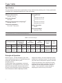
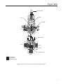
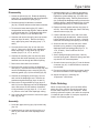
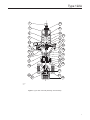
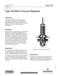
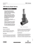
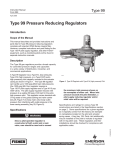
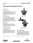
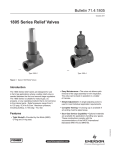
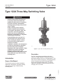
Type 122A
Instruction Manual
Form 2279
March 2013
Type 122A Three-Way Switching Valve
!
WARNING
Failure to follow these instructions or
to properly install and maintain this
equipment could result in an explosion,
fire and/or chemical contamination
causing property damage and personal
injury or death.
Fisher® switching valves must be
installed, operated, and maintained
in accordance with federal, state, and
local codes, rules and regulations,
and Emerson Process Management
Regulator Technologies, Inc. (Regulator
Technologies) instructions.
If the switching valve vents gas or a
leak develops in the system, service
to the unit may be required. Failure
to correct trouble could result in a
hazardous condition.
Installation, operation, and maintenance
procedures performed by unqualified
personnel may result in improper
adjustment and unsafe operation. Either
condition may result in equipment
damage or personal injury. Only
qualified personnel shall install, operate,
and maintain the Type 122A three-way
switching valve.
Introduction
Scope of the Manual
Figure 1. Type 122A Three-Way Switching Valve
Description
The Type 122A three-way switching valve (see
Figure 1) is a high-capacity, economical three-way
pneumatic switching valve for on-off applications. This
valve can be used for diverging or converging gaseous
service, diverging liquid service with gas-loaded
liquids, and converging liquid service. Six spring
ranges are available for control pressures from 3 to
150 psig / 0.21 to 10.3 bar.
D100263X012
This instruction manual includes installation,
adjustment, maintenance, and parts ordering
information for the Type 122A three-way
switching valve.
W3141-1
www.fisherregulators.com
Type 122A
Specifications
The Specifications section lists the specifications for Type 122A three-way switching valve. Factory specification
is stamped on the nameplate fastened on the valve at the factory.
Maximum Inlet Pressure(1)
150 psig / 10.3 bar
Flow Coefficients
Cg(2)
Connection A to B: 138
Connection A to C: 131
Set Pressure Ranges(1)
See Table 1
Maximum Control Pressure to Diaphragm(1)
150 psig / 10.3 bar
C1
Connection A to B: 28.0
Connection A to C: 32.5
Temperature Capabilities(1)
-20 to 150°F / -29 to 66°C
Control Connection
1/4 NPT
Approximate Weight
5 pounds / 2.3 kg
1. The pressure/temperature limits in this Instruction Manual and any applicable standard or code limitation should not be exceeded.
2. At an inlet pressure of 25 psig / 1.7 bar and with full pressure drop across the body.
Table 1. Set Pressure Ranges
SET PRESSURE RANGES
PRESSURE BUILD-UP
ABOVE SETPOINT
REQUIRED FOR
FULL STROKE
SPRING
WIRE DIAMETER
SPRING
FREE LENGTH
SPRING PART
NUMBER
SPRING
COLOR
psig
bar
psi
bar
Inches
mm
Inches
mm
3 to 15
5 to 20
5 to 35
0.21 to 1.0
0.35 to 1.4
0.35 to 2.4
10
13.5
22
0.69
0.93
1.5
0.168
0.187
0.218
4.27
4.75
5.54
2.94
2.81
2.50
74.6
71.4
63.5
1D892327022
1D751527022
1D665927022
Red
Cadmium
Blue
30 to 60
40 to 100
60 to 150
2.1 to 4.1
2.8 to 6.9
4.1 to 10.3
30
54
66
2.1
3.7
4.6
0.234
0.283
0.240
5.94
7.19
6.10
2.57
2.31
2.63
65.2
58.7
66.8
1D7455T0012
1E543627142
1P901327142
Green
Yellow
Brown
Principle of Operation
Refer to Figure 2. The flow through the Type 122A
valve is normally from port A to C, with the spring force
holding the valve plug down on port B
(diverging service).
As the pressure under the diaphragm is increased
through port D, it acts against the force of the spring.
When the control pressure overcomes the force of
the spring, the valve begins to stroke, opening port B.
Once the pressure under the diaphragm reaches
2
setpoint plus build-up, the valve completes its stroke
and the port C seat ring is closed. The valve will only
fully stroke when build-up above setpoint is achieved.
The point at which the valve completes its stroke
and the pressure change necessary to do this are
dependent on the spring rate and the set point
chosen. The set pressure is easily changed by
adjusting the screw at the top of the valve.
Type 122A
ADJUSTING SCREW
SPRING
STEM
DIAPHRAGM
PORT D
UPPER VALVE SEAT
PORT A
PORT C
VALVE
LOWER VAVE SEAT
W0157
INLET PRESSURE
OUTLET PRESSURE
ATMOSPHERIC PRESSURE
INLET
PRESSURE
INLET
PRESSURE
PORT B
OUTLET
PRESSURE
OUTLET
PRESSURE
ATMOSPHERIC
PRESSURE
ATMOSPHERIC
PRESSURE
Figure 2. Type 122A Three-Way Switching Valve Operational Schematic
3
Type 122A
Installation
!
!
WARNING
To avoid personal injury or equipment
damage caused by bursting of
pressure-retaining parts or explosion
of accumulated gas, do not exceed
the pressure or temperature limits
in Specifications, and do not use the
Type 122A valve for installations where
water hammer can be experienced.
1. The switching valve may be installed in any
position. Position the vent (key 29, Figure 3) so
that the vent opening is facing downward. Protect
the vent opening against the entrance of moisture
or any other material that could plug the vent.
2. Apply pipe compound to external pipeline threads.
Connect piping to the body connections.
3. Connect the control pressure line to the 1/4 NPT
connection in the lower diaphragm case.
Overpressure Protection
Type 122A three-way switching valves have
maximum outlet pressure ratings that are lower than
their maximum inlet pressure ratings. A pressurerelieving or pressure-limiting device is needed if
inlet pressure can exceed the maximum outlet
pressure rating. Overpressuring any portion of a
switching valve or associated equipment may cause
leakage, parts damage, or personal injury due to
bursting of pressure-containing parts or explosion of
accumulated gas. Switching valve operation within
ratings does not preclude the possibility of damage
from external sources or from debris in the pipeline.
A switching valve should be inspected for damage
periodically and after any overpressure condition.
Startup and Adjustment
Key numbers is referenced in Figure 3.
1. With proper installation completed and
downstream equipment properly adjusted, slowly
open the upstream and downstream shutoff valve
(when used) while using pressure gauges to
monitor pressure.
4
WARNING
To avoid personal injury, property
damage, or equipment damage caused
by bursting of pressure containing
parts or explosion of accumulated
gas, never adjust the control spring to
produce an outlet pressure higher
than the upper limit of the outlet
pressure range for that particular
spring. If the desired outlet pressure
is not within the range of the control
spring, install a spring of the proper
range according to the diaphragm parts
maintenance procedure.
2. Refer to the nameplate (key 25, Figure 3) for
the spring range. To change the spring setting,
loosen the locknut (key 30, Figure 3), and rotate
the adjusting screw (key 7, Figure 3). Rotating
the adjusting screw clockwise into the spring
case (key 1, Figure 3) increases the control
pressure at which the valve switches. Rotating
the adjusting screw counterclockwise decreases
the switching pressure.
Maintenance
Parts are subject to normal wear and must be
inspected and replaced periodically. The frequency of
parts inspection and replacement depends upon the
severity of service conditions.
Instructions are given below for complete disassembly
and assembly. Disassemble the valve only as far as
needed. Then, begin the “Assembly” procedure at the
appropriate step.
Key numbers used in these procedures are shown
in Figure 3.
!
WARNING
To avoid personal injury and equipment
damage caused by sudden release
of process pressure or uncontrolled
process fluid, isolate the valve from all
pressure, and release all pressure from
the valve body and diaphragm casing
before attempting maintenance.
Type 122A
Disassembly
1. Loosen the locknut (key 30). Rotate the adjusting
screw (key 7) counterclockwise until all compression
has been relieved from the spring (key 3).
2. Disconnect piping from the bottom connector
(key 36). Unscrew and remove the bottom connector.
3. To remove the lower seat ring (key 37), insert a
hexagonal bar into the seat ring hole, and use the bar
to unscrew the seat ring. The hexagonal hole in the
seat ring is 7/16-inch / 11 mm across the flats.
4. Unscrew and remove the spring case cap screws
and nuts (keys 26 and 4). Remove the spring
case, upper spring seat, and spring (keys 1, 31,
and 3).
3. Install the washer (key 17) and three felt washers
(key 18) into the valve end of the diaphragm case.
Replace the guide bushings (key 15) in each end
of the diaphragm casing. Carefully insert the stem
(key 5) through the diaphragm casing to be sure the
parts are aligned. Attach the washers (key 14) with
self-tapping screws (key 16). Remove the stem.
4. Replace the body gasket and snap ring (keys 21
and 20). Secure the diaphragm case to the body
with the union nut (key 19).
5. Coat the threads on the valve end of the stem
with high strength threadlocker. Attach the disk
holder assembly (key 22) to the stem. Carefully
install the stem through the opening of the body.
5. Unscrew the hex nuts (key 4) from the stem
(key 5). Remove the spring guide, diaphragm
head, diaphragm, O-ring, back-up ring, and
washer (keys 6, 8, 9, 12, 13, and 10).
6. Screw two hex lock nuts onto the stem. Install
the back-up ring, washer, O-ring, diaphragm,
diaphragm head, and spring guide (keys 13, 10,
12, 9, 8, and 6). Secure with two hex lock
nuts (key 4).
6. Unscrew the remaining hex nuts from the stem,
and pull the disk holder assembly (key 22) and
attached stem out through the bottom opening.
7. Set the spring and spring seat (keys 3 and 31)
onto the spring guide. Attach the spring case with
cap screws in a crisscross pattern.
7. Remove the disk holder from the stem.
8. Screw the lower seat ring (key 37) into the bottom
connector (key 36). Install the bottom connector
into the body.
8. Disconnect the control line from the diaphragm
case (key 2). Unscrew the union nut (key 19), and
remove the diaphragm case, snap ring (key 20),
and body gasket (key 21) from the body (key 23).
9. Unscrew the self-tapping screws (key 16) from
each end of the diaphragm case. Remove the
washers and guide bushings (keys 14 and 15).
10. Remove the O-ring and back-up rings (keys 12
and 13) from the diaphragm end of the diaphragm
case, and remove the felt washers, flat washer,
O-ring, and back-up rings (keys 18, 17, 12, and
13) from the valve end of the diaphragm casing.
11. Use a thin-wall socket wrench to remove the upper
seat ring (key 24).
9. Re-connect piping to the bottom connector and to
the control connection in the diaphragm casing.
10.Adjust the spring by following the
“Adjustment” instructions.
Parts Ordering
When corresponding with your local Sales Office
about this valve, mention the serial number and
all other data stamped on the nameplate. When
ordering replacement parts, also state the complete
11-character part number of each part required as
found in the following parts list.
Assembly
1. Screw the upper seat ring (key 24) into the body
(key 23).
2. Install the back-up rings and O-rings (keys 13
and 12) into each end of the diaphragm case
(key 2).
5
Type 122A
Parts List
Key
Description
Part Number
1
Spring Case,
Aluminum
2P901508012
2
Lower Diaphragm Case,
Cast iron
2L918419012
3
Spring
See Table 1
4
Hex Nut, Plated steel
(12 required)
1A3915X0022
5*
1R177435162
Stem, 316 Stainless steel
6
Spring Guide,
Plated steel
1D666625072
7 Adjusting Screw,
Plated steel 1D995448702
8 Diaphragm Plate,
Plated steel 1D666428982
9* Diaphragm,
Neoprene (CR)
1D666302102
10
Key
20
Description
Snap Ring, Plated steel
1A832504032
22* Disk Holder Assembly
Aluminum/Nitrile (NBR)
Stainless steel/Nitrile (NBR)
Stainless steel/Fluorocarbon (FKM) 1R1772000A2
1R1772X00A2
1R1772X0032
23 Body, Cast iron
3/4 NPT
1 NPT
WCC Steel
3/4 NPT 1 NPT 25
1E472706992
13* Back-up Ring, Leather
(5 required)
28 Drive Screw, Plated steel
(4 required)
14B0155X012
14 Retaining Washer, Stainless steel
(2 required)
1K786935022
15* Guide Bushing, Iron
(2 required)
1K787021052
16 Self-Tapping Screw, Plated steel
(4 required)
1J336928982
17
1K787135022
1K787206992
19 Union Nut,
Ductile iron
1E471119062
*Recommended spare parts
6
1E162622012
1K886222012
1B810309012
1B8103X0012
Name Plate
1D716228982
Washer, Stainless steel
1D3124X0022
1D3125X0022 24* Upper Valve Seat
Aluminum
Stainless steel
12* O-Ring, Nitrile (NBR)
(3 required)
18* Washer, Neoprene (CR)/Felt
(3 required)
1A832648722
21 Body Gasket,
Asbestos
26 Cap Screw, Plated steel
(8 required)
Washer, Plated steel
Part Number
----------1B720924052
1E501728982
29
Vent Assembly
30
Locknut, Zinc-plated steel
1D667728982
31
Upper Spring Seat, Plated steel
1D667125072
36
Bottom Flange, Plated steel
1
R177524092
37* Lower Valve Seat
Aluminum
Stainless steel
WCC Steel
3/4 NPT
1 NPT
EMY602X1-A12
1R177309012
1R1773X00A2
1E162622012
1K886222012
Type 122A
7
30
1
31
3
28
5
4
29
8
9
4
10
15
12
14
13
13
2
20
19
21
A
24
C
6
26
16
12
17
18
22
23
37
25
36
B
20A9801-A
A2606
Figure 3. Type 122A Three-Way Switching Valve Assembly
7
Type 122A
Industrial Regulators
Natural Gas Technologies
TESCOM
Emerson Process Management
Regulator Technologies, Inc.
Emerson Process Management
Regulator Technologies, Inc.
Emerson Process Management
Tescom Corporation
USA - Headquarters
McKinney, Texas 75069-1872, USA
Tel: +1 800 558 5853
Outside U.S. +1 972 548 3574
USA - Headquarters
McKinney, Texas 75069-1872, USA
Tel: +1 800 558 5853
Outside U.S. +1 972 548 3574
USA - Headquarters
Elk River, Minnesota 55330-2445, USA
Tels: +1 763 241 3238
+1 800 447 1250
Asia-Pacific
Shanghai 201206, China
Tel: +86 21 2892 9000
Asia-Pacific
Singapore 128461, Singapore
Tel: +65 6770 8337
Europe
Selmsdorf 23923, Germany
Tel: +49 38823 31 287
Europe
Bologna 40013, Italy
Tel: +39 051 419 0611
Europe
Bologna 40013, Italy
Tel: +39 051 419 0611
Chartres 28008, France
Tel: +33 2 37 33 47 00
Asia-Pacific
Shanghai 201206, China
Tel: +86 21 2892 9499
Middle East and Africa
Dubai, United Arab Emirates
Tel: +971 4811 8100
For further information visit www.fisherregulators.com
The Emerson logo is a trademark and service mark of Emerson Electric Co. All other marks are the property of their prospective owners. Fisher is a mark owned by Fisher Controls International LLC,
a business of Emerson Process Management.
The contents of this publication are presented for informational purposes only, and while every effort has been made to ensure their accuracy, they are not to be construed as warranties or
guarantees, express or implied, regarding the products or services described herein or their use or applicability. We reserve the right to modify or improve the designs or specifications of such
products at any time without notice.
Emerson Process Management Regulator Technologies, Inc. does not assume responsibility for the selection, use or maintenance of any product. Responsibility for proper selection, use and
maintenance of any Emerson Process Management Regulator Technologies, Inc. product remains solely with the purchaser.
©Emerson Process Management Regulator Technologies, Inc., 1980, 2013; All Rights Reserved