1
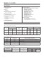
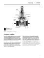
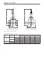
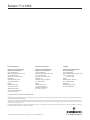
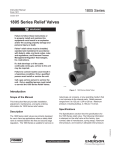
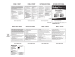
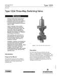
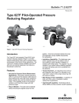
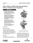
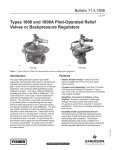
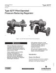
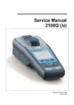
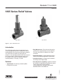
Bulletin 71.4:1805
October 2011
1805 Series Relief Valves
P1026
1805G
Type 1805-2
Type 1805-4
Figure 1. Typical 1805 Relief Valves
Introduction
The 1805 Series relief valves are designed for use
in farm tap applications where a safety relief valve is
needed between the first and second stage regulators.
The 1805 Series is suitable for natural gas, air,
propane, or any operating medium that is not corrosive
to the internal parts. Relief pressures range from 5
to 125 psig / 0,34 to 8,6 bar. Maximum pressure, including buildup, is 150 psig / 10,3 bar.
• Easy Maintenance—The union nut allows quick
removal of the cage assembly for trim inspection.
The valve can be back in operation in a matter
of minutes.
Features
• Sour Gas Service Capability—Optional materials
are available for applications handling sour gases.
These constructions comply with the
recommendations of the NACE International
Standards MR0175 and MR0103.
• Complete Venting—A closing cap is available if
all venting must be piped away.
D100160X012
• Tight Shutoff—Provided by the Nitrile (NBR)
O-ring and O-ring seat.
• Simple Adjustment—A single adjusting screw is
used to meet individual application requirements.
www.fisherregulators.com
Bulletin 71.4:1805
Specifications
Available Constructions
See Table 2
Construction Materials
Body: Cast Iron (all sizes) and Ductile Iron (NACE)
(3/4 and 1 NPT body sizes)
Diaphragm: Nitrile (NBR)
Valve Guide Orifice: Aluminum
O-Ring Washer: Stainless steel
O-Rings: Nitrile (NBR)
O-Ring Holder: Aluminum
Diaphragm Plate: Brass
Upper Spring Seat: Plated steel
Union Nut: Ductile Iron
Vent Screen: Stainless steel
Body Style
Globe body
Body Sizes and End Connection Style
3/4, 1, 1-1/2, or 2 NPT
Maximum Inlet Pressure(1)
150 psig / 10,3 bar including buildup
Relief Valve Set Pressure Ranges
See Table 1
Approximate Weights
3/4 to 1 NPT bodies: 5 pounds / 2 kg
1-1/2 to 2 NPT bodies: 13 pounds / 6 kg
Flow and IEC Sizing Coefficients
See Table 3
Temperature Capabilities(1)
-20° to 150°F / -29° to 66°C
1. The pressure/temperature limits in this Bulletin or any applicable standard limitation should not be exceeded.
Table 1. Relief Valve Set Pressure Ranges
RELIEF PRESSURE RANGE
BODY SIZE, NPT
SPRING PART
NUMBER
SPRING COLOR
CODE
psig
bar
3/4 or 1
5 to 35
10 to 60
20 to 125
0,34 to 2,4
0,69 to 4,1
1,4 to 8,6
1B986027212
1B788327022
1B788427022
1-1/2 or 2
5 to 20
10 to 50
35 to 125
0,34 to 1,4
0,69 to 3,4
2,4 to 8,6
1D892327022
1D665927022
1E543627142
SPRING FREE LENGTH
SPRING WIRE DIAMETER
Inches
mm
Inches
mm
Green
Silver
Blue
2.25
2.13
1.94
57,2
54,1
49,3
0.12
0.14
0.18
3,05
3,56
4,57
Red
Blue
Yellow
2.94
2.50
2.31
74,7
63,5
58,7
0.17
0.22
0.28
4,32
5,59
7,11
Table 2. Available Constructions
TYPE NUMBER
BODY SIZE AND END
CONNECTION, NPT
DISTINCTIVE CONSTRUCTION FEATURES
1805-2
3/4 or 1
Cast iron spring case, closing cap with 1/4 NPT vent placed over the adjusting screw
1805-3
1-1/2 or 2
Cast iron spring case, closing cap with 1/4 NPT vent placed over the adjusting screw
1805-4
3/4 or 1
Cast iron spring case
1805-5
1-1/2 or 2
Cast iron spring case
1805-7
3/4 or 1
Cast iron spring case, closing cap with 1/4 NPT vent placed over the adjusting
screw, and screen in outlet
Table 3. Flow and IEC Sizing Coefficients
BODY SIZE, NPT
3/4 to 1
1-1/2 to 2
2
C1
35
Km
0.79
IEC SIZING COEFFICIENTS
XT
FD
0.73
0.39
0.94
0.44
FL
0.89
Bulletin 71.4:1805
Type XXXX
Month Year
Type XXXX
UPPER
SPRING
SEAT
DIAPHRAGM
HEAD
DIAPHRAGM
VALVE GUIDE
ORIFICE
UNION NUT
O-RING
O-RING
HOLDER
BODY
MXXXX
VALVE
SEAT
SURE
INLET PRESSURE
OUTLET PRESSURE
ATMOSPHERIC PRESSURE
A6671
O-RING WASHER
INLET
PRESSURE
INLET
PRESSURE
O-RING
OUTLET/EXHAUST
PRESSURE
OUTLET PRESSURE
ATMOSPHERIC
PRESSURE
ATMOSPHERIC
PRESSURE
Figure 2. 1805 Series Operational Schematic
Principle PILOT
of Operation
SUPPLY PRESSURE
INTERMEDIATE BLEED PRESSURE
PRESSURE
See Figure 2. PRE-EXPANSION
ReliefPRESSURE
valves
respond to changes in
VACUUM
BYPASS PRESSURE
upstream pressure.
If
upstream
pressure increases
PUMP PRESSURE
BACKrelief
PRESSURE
and exceeds the
valve setting, the valve will
open and allow gas to vent to the atmosphere. When
upstream pressure returns to normal level (below the
setting of the relief valve), the relief valve automatically
closes and normal system operation resumes.
PILOTSeries
SUPPLY
PRESSURE
In the 1805
relief
valves, the upstream pressure
INTERMEDIATE
BLEED
PRESSURE
registers
underneath the
diaphragm.
Gas reaches
PRE-EXPANSION PRESSURE
the diaphragm
through the space between the O-ring
VACUUM PRESSURE
holder BYPASS
and the valve
guide orifice in 3/4 and 1 NPT
PRESSURE
bodies PUMP
or through
registration
holes in the valve guide
PRESSURE
orifice in
1-1/2PRESSURE
and 2 NPT bodies.
BACK
When the upstream pressure increases beyond the
spring setting, the force underneath the diaphragm
overcomes spring compression. The O-ring holder
moves upward, carrying the O-ring away from the
valve seat. This opens the flow line, allows gas to
flow to the atmosphere, and relieves the overpressure
condition. When upstream pressure registered on
the diaphragm decreases to a level below that of
the spring setting of the relief valve, the spring force
pushes the diaphragm plate and O-ring holder toward
the valve seat. Contact between O-ring and valve
seat prevents further flow to atmosphere.
3
Bulletin 71.4:1805
1-1/2 AND 2 NPT BODIES
3/4 AND 1 NPT BODIES
150
/ 10,3
125
/ 8,6
125
/ 8,6
75 / 5,2
75
50
/ 3,4
25
/ 1,7
/ 10,3
125
/ 8,6
50 / 3,4
/ 6,9
100
75
/ 5,2
50
/ 3,4
40 / 2,8
/ 1,7
25
25 / 1,7 SETPOINT (1)
INLET PRESSURE (SETPOINT PLUS BUILDUP), psig / bar
/ 5,2
50 / 3,4 SETPOINT(1)
SPRING 1D665927022
/ 6,9
100
60 / 4,1
/ 8,6
/ 6,9
100
20 / 1,4
75
/ 5,2
10 / 0,69
50
/ 3,4
25
/ 1,7
5 / 0,34 SETPOINT (1)
0/
0
5/
0,13
10 /
0,27
15 /
0,40
20 /
0,54
25 /
0,67
30 /
0,80
35 /
0,94
40 /
1,07
B0812
50 / 3,4 SETPOINT
(1)
50
/ 3,4
25
/ 1,7
150
/ 10,3
/ 8,6
125
50 / 3,4
100
Figure 3. Relief Capacity Curves
/ 6,9
40 / 2,8
/ 5,2
75
/ 3,4
50
/ 1,7
150
/ 10,3
125
/ 8,6
/ 6,9
100
20 / 1,4
/ 5,2
75
10 / 0,69
/ 3,4
50
/ 1,7
25
5 / 0,34 SETPOINT(1)
0/
0
20 /
0,54
40 /
1,07
60 /
1,61
CAPACITY IN THOUSAND SCFH, AT 60°F AND 14.7 psia /
Nm3/h, AT 0°C AND 1,01325 bar OF 0.6 SPECIFIC GRAVITY
NATURAL GAS
1. SETPOINT IS TO BE INTERPRETED AS BUBBLE POINT
*MAXIMUM PRESSURE INCLUDING BUILDUP - 150 psig / 10,3 bar AT 150°F / 66°C.
/ 5,2
75
20 / 1,4 SETPOINT(1)
/ 10,3
25 / 1,7
60 / 4,1
25
35 / 2,4
125
/ 6,9
100
30 / 2,1
SPRING 1D892327022
SPRING 1B986027212
SPRING 1E543627142
/ 10,3
150
4
75 / 5,2
100 / 6,9
125 / 8,6
100 / 6,9
150
SPRING 1B788327022
INLET PRESSURE (SETPOINT PLUS BUILDUP), psig / bar
SPRING 1B788427022
125 / 8,6
150
80 /
2,14
100 /
2,68
120 /
3,22
140 /
3,75
160 /
4,29
180 /
4,82
200 /
5,36
Bulletin 71.4:1805
W1258
Figure 4. Type 1805-3 Closing Cap Sectional View
Installation
Overpressure
The 1805 Series relief valves may be installed in any
position. However, the outlet connection and vents
must be protected against the entrance of rain, snow,
insects, or any other foreign material that may plug the
outlet or affect the opening and closing of the valve. If it
is necessary to pipe away the outlet, remove the outlet
screen (if one is present).
Relief pressure ratings are from 5 to 125 psig /
0,34 to 8,6 bar. The maximum inlet pressure,
including buildup, is 150 psig / 10,3 bar. System
operation within these limitations does not eliminate
the possibility of damage from external sources or
from debris in the gas line. The relief valve should
be inspected for damage regularly and after any
overpressure condition.
Flow through the valve must be as indicated by the flow
direction arrow on the body. For dimensional information,
see Figure 5.
Capacity Information
Natural gas relieving capacities at selected inlet
pressures (setpoint plus buildup) are given in
Figure 3. Flows are in thousands SCFH (60°F and
14.7 psia) of 0.6 specific gravity natural gas. To
determine the equivalent capacities for other gases,
multiply the capacity obtained from the curves by the
following appropriate conversion factor: 0.775 for air,
0.789 for nitrogen, 0.625 for propane, or 0.548 for
butane. For gases of other specific gravities, multiply
the given capacity by 0.775, and divide by the square
root of the appropriate specific gravity.
Universal NACE Compliance
Optional materials are available for applications
handling sour gases. These constructions comply
with the recommendations of NACE International sour
service standards.
The manufacturing processes and materials used by
Emerson assure that all products specified for sour
gas service comply with the chemical, physical, and
metallurgical requirements of NACE MR0175 and/or
NACE MR0103. Customers have the responsibility to
specify correct materials. Environmental limitations
may apply and shall be determined by the user.
Then, if capacity is desired in normal cubic meters per
hour (Nm3/h) at 0°C and 1,01325 bar, multiply values
obtained from Figure 3 by 0.0268.
5
Bulletin 71.4:1805
1/4 NPT
D
D
C
C
B
B
A
AF2211
AH6967
TYPE 1805-2, 1805-3, OR 1805-7 WITH CLOSING CAP
A
TYPE 1805-4 OR 1805-5 WITHOUT CLOSING CAP
Figure 5. 1805 Series Dimensional Drawings
Table 4. 1805 Series Dimensions
TYPES
1805-2/ 1
1805-4
1805-7/ 1
1805-3/ 1
1805-5
1. With closing cap.
6
BODY SIZE AND
END CONNECTION
STYLE, NPT
MATERIAL
DIMENSION, INCHES / mm
A
B
C
D / max
Cast iron
3.62 / 92
1.81 / 46
1.00 / 25
6.44 / 164
Ductile iron / NACE
3.88 / 99
1.94 / 49
1.38 / 35
6.44 / 164
Cast iron
3.62 / 92
1.81 / 46
1.00 / 25
6.44 / 164
Ductile iron / NACE
3.88 / 99
1.94 / 49
1.38 / 35
6.44 / 164
1-1/2
Cast iron
5.88 / 149
2.94 / 75
1.69 / 43
9.12 / 232
2
Cast iron
5.88 / 149
2.94 / 75
1.69 / 43
9.12 / 232
3/4
1
Bulletin 71.4:1805
Ordering Information
Please give the following information when ordering
any of the 1805 Series relief valves:
1. Type Number
2. Body Size and Material
3. Desired Relief Pressure Range
Ordering Guide
Type (Refer to Table 2 for Construction Features)
(Select One)
1805-2***
1805-3***
1805-4**
1805-5***
1805-7***
Body Size and End Connection Style (Select One)
3/4 NPT***
1 NPT***
1-1/2 NPT**
2 NPT***
Relief Set Pressure Range (Select One)
3/4 or 1 NPT Body Size:
5 to 35 psig / 0,34 to 2,4 bar, Green***
10 to 60 psig / 0,69 to 4,1 bar, Silver***
20 to 125 psig / 1,4 to 8,6 bar, Blue***
1-1/2 or 2 NPT Body Size:
5 to 20 psig / 0,34 to 1,4 bar, Red***
10 to 50 psig / 0,69 to 3,4 bar, Blue***
35 to 125 psig / 2,4 to 8,6 bar, Yellow***
Replacement Parts Kit (Optional)
Yes, send one replacement parts kit to match this order
Body Material (Select One)
Cast Iron (All sizes)**
Ductile Iron (NACE) (3/4 or 1 NPT body size only)**
Specification Worksheet
Application:
Specific Use
Line Size
Gas Type and Specific Gravity
Gas Temperature
Regulators Quick Order Guide
***
**
*
Readily Available for Shipment
Allow Additional Time for Shipment
Special Order, Constructed from Non-Stocked Parts. Consult your local
Sales Office for Availability.
Relief Valve Size:
Brand of upstream regulator?
Orifice size of the upstream regulator?
Wide-open coefficient of the upstream regulator?
Pressure:
Maximum Inlet Pressure (P1max)
Minimum Inlet Pressure (P1min)
Downstream Pressure Setting(s) (P2)
Maximum Flow (Qmax)
Performance Required:
Accuracy Requirements?
Need for Extremely Fast Response?
Other Requirements:
Availability of the product being ordered is determined by the component with the
longest shipping time for the requested construction.
7
Bulletin 71.4:1805
Industrial Regulators
Natural Gas Technologies
TESCOM
Emerson Process Management
Regulator Technologies, Inc.
Emerson Process Management
Regulator Technologies, Inc.
Emerson Process Management
Tescom Corporation
USA - Headquarters
McKinney, Texas 75069-1872, USA
Tel: +1 800 558 5853
Outside U.S. +1 972 548 3574
USA - Headquarters
McKinney, Texas 75069-1872, USA
Tel: +1 800 558 5853
Outside U.S. +1 972 548 3574
USA - Headquarters
Elk River, Minnesota 55330-2445, USA
Tels: +1 763 241 3238
+1 800 447 1250
Asia-Pacific
Shanghai 201206, China
Tel: +86 21 2892 9000
Asia-Pacific
Singapore 128461, Singapore
Tel: +65 6770 8337
Europe
Selmsdorf 23923, Germany
Tel: +49 38823 31 287
Europe
Bologna 40013, Italy
Tel: +39 051 419 0611
Europe
Bologna 40013, Italy
Tel: +39 051 419 0611
Gallardon 28320, France
Tel: +33 2 37 33 47 00
Asia-Pacific
Shanghai 201206, China
Tel: +86 21 2892 9499
Middle East and Africa
Dubai, United Arab Emirates
Tel: +971 4811 8100
For further information visit www.fisherregulators.com
The Emerson logo is a trademark and service mark of Emerson Electric Co. All other marks are the property of their prospective owners. Fisher is a mark owned by Fisher Controls International LLC,
a business of Emerson Process Management.
The contents of this publication are presented for informational purposes only, and while every effort has been made to ensure their accuracy, they are not to be construed as warranties or
guarantees, express or implied, regarding the products or services described herein or their use or applicability. We reserve the right to modify or improve the designs or specifications of such
products at any time without notice.
Emerson Process Management does not assume responsibility for the selection, use or maintenance of any product. Responsibility for proper selection, use and maintenance of any Emerson
Process Management product remains solely with the purchaser.
©Emerson Process Management Regulator Technologies, Inc., 2011; All Rights Reserved