1
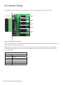
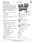
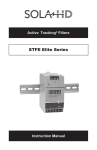
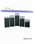
IntelliSlot® Relay Card
User Manual
Contents
1.0 Introduction
3
1.1 Inspecting Shipment on Receipt. . . . . . . . . . . . . . . . . . . . . . . . . . . . . . . . . . . . . . . . . . 3
2.0 Installation
4
2.1 Required Parts & Tools. . . . . . . . . . . . . . . . . . . . . . . . . . . . . . . . . . . . . . . . . . . . . . . 4
2.2 Installation Instructions. . . . . . . . . . . . . . . . . . . . . . . . . . . . . . . . . . . . . . . . . . . . . . 4
3.0 PIN Configuration
5
Table 1: IntelliSlot Relay Card PIN Configuration . . . . . . . . . . . . . . . . . . . . . . . . . . . . . . . . . . . . 5
4.0 Jumper Setup
6
Table 2: Jumper Connections . . . . . . . . . . . . . . . . . . . . . . . . . . . . . . . . . . . . . . . . . . . . . 6
5.0 Technical Support
7
5.1 Contact Information. . . . . . . . . . . . . . . . . . . . . . . . . . . . . . . . . . . . . . . . . . . . . . . . 7
While every precaution has been taken to ensure accuracy and completeness in this manual, EGS Electrical Group, LLC. assumes no responsibility, and disclaims all
liability for damages resulting from use of this information or for any errors or omissions.
The SolaHD and Emerson logos are registered in the U.S. Patent and Trademark Office. All other product or service names are the property of their registered owners.
©2011 EGS Electrical Group, LLC. All rights reserved. Specifications are subject to change without notice.
1.0 Introduction
The IntelliSlot relay card (IS-RELAY) provides contact closure for remote monitoring of alarm conditions in your SolaHD UPS.
The IntelliSlot relay card is easy to install and integrates with other relay contact monitoring systems.
This advanced power management device is designed to function in units with a IntelliSlot port, such as:
•
S4KC Series
•
S5K Series
Please visit our Web site at www.solahd.com for the current list of supported products.
On supported units, the inverter shut-off command can be controlled from the computer directly connected to the UPS (via
the factory-installed DB9 connector) and will conserve battery power after the workstation shutdown is complete.
The IntelliSlot relay card is rated for 24 V ac/V dc at 1 A.
1.1 Inspecting Shipment on Receipt
Upon accepting shipment, inspect the packaging and product for any damaged or missing parts. If any damage is observed,
report it to the shipping company and your local SolaHD representative immediately. If any components are missing, contact
your local SolaHD representative for replacement.
Items included with the shipment are:
•
IntelliSlot relay card protected by an anti-static bag
•
User manual
intellislot relay card User Manual | 3
2.0 Installation
2.1 Required Parts & Tools
NOTE: Make sure you have the following parts and tools before you begin the installation.
•
IntelliSlot relay card (provided)
•
#2 (medium) Phillips or small flathead screwdriver
2.2 Installation Instructions
1. Turning off the UPS prior to installation is suggested, although not required.
2. Locate the IntelliSlot port. (See examples in Figure 1.) Refer to the UPS user manual for port location and orientation.
3. Remove the two retaining screws from the IntelliSlot port cover plate (see Figure 1). Save the screws for reassembly in
Step 5.
4. Insert the IntelliSlot relay card. Make sure the holes are aligned with those on the UPS. Initially, the card should slide in
freely as you carefully align the screw holes. As you feel it click into place, press firmly to ensure solid seating in the slot.
5. Use the screwdriver to secure the IntelliSlot relay card to the UPS chassis with the two retaining screws removed in Step 3.
Make sure the screws are snug, not tight, to avoid damage to the device.
IntelliSlot
Relay Card
Remove screws
Figure 1: Installation
6. Use these guidelines for terminal block specifications:
Acceptable wire size: 24–16 AWG
Wire strip length: 0.24–0.28 in. (6–7 mm)
Please proceed to Sections “3.0 Pin Configuration” and “4.0 Jumper Setup” to configure the terminal blocks and jumpers.
intellislot relay card User Manual | 4
3.0 PIN Configuration
The IntelliSolt relay card has two terminals blocks, TB1 (green, numbered 1–9) and TB2 (black, numbered 10–18), as shown in
Figure 2.
1
10
TB1
green
TB2
black
9
18
Figure 2: PIN location & numbering
Please refer to the UPS User manual for the UPS terminal block configuration. The PIN functions in Table 1 apply only to the
SolaHD units listed in Section “1.0 Introduction”.
Table 1: IntelliSlot Relay Card PIN Configuration
PIN
Function
Operation
1
Common — Low Battery
2
Low Battery
Closed if Low Battery point occurs
Closed if battery is OK
3
Low Battery
4
Common — UPS Fault
5
UPS Fault
Closed if UPS Fault occurs
6
UPS Fault
Closed if no UPS failure
7
Common — On Battery
8
On Battery
Closed if On Battery power (utility failure)
9
On Battery
Closed if not On Battery power (utility OK)
10
Signal Ground
Use for UPS Any-Mode Shutdown
11
Signal Ground
Use for UPS Any-Mode Shutdown
12
UPS Any-Mode Shutdown
Turn UPS output off when shorted to PIN 10 or 11
13
Summary Alarm
Closed if no alarm conditions are present
14
Summary Alarm
Closed if Summary Alarm occurs
15
Common — Summary Alarm
16
On UPS
Closed if ON UPS (inverter) power
17
On Bypass
Closed if On Bypass
18
Common — On Bypass
intellislot relay card User Manual | 5
4.0 Jumper Setup
The IntelliSlot relay card has five jumpers, P3 through P7, as shown in Figure 2. Each jumper connects two PINs.
Front of card
Jumper
P6
Jumper
P5
Jumper
P4
Jumper
P3
Jumper
P7
Figure 3: Jumper location & numbering
By default, all five jumpers have shunts installed. The two PINs are shunted together to provide the functions shown in Table 2,
allowing relay commons to be tied together.
NOTE: The jumpers should be removed if there are any external voltage sources that may intentionally or inadvertently be
connected to the relay. Removing the shunt from any two PINs breaks the connection between the relay commons so they
are not tied together.
Table 2: Jumper Connections
Jumper
Relay
P6
On Battery
P5
UPS Fault
P4
Low Battery
P3
On Bypass
P7
Summary Alarm
intellislot relay card User Manual | 6
5.0 Technical Support
5.1 Contact Information
To contact SolaHD technical support, please use one of the following methods:
•
Phone: 1.800.377.4384 (US) or 1.847.268.6651 (International)
•
E-mail: [email protected]
•
Web site: www.solahd.com
intellislot relay card User Manual | 7
SolaHD • 1.800. 377.4384 (US) • 1.847.268.6651 (International) • www.solahd.com
P/N: A272-240 Rev 0
May 2011