1
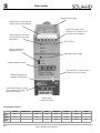
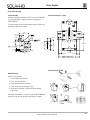
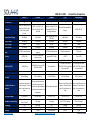
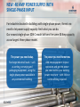
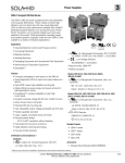
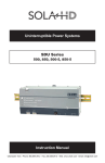
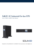
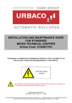
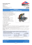
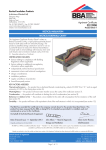
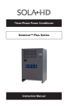
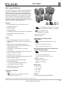
3
Power Supplies
SDN-C Compact DIN Rail Series
The SDN-C DIN rail power supplies are the next generation
of the popular SDN series. These models combine high
efficiency and compact size with new visual diagnostic
LEDs to offer the most performance available from SolaHD.
Essential industrial features such as Sag Immunity, Power
Factor Correction, and universal voltage input have been
retained in this series. Wide temperature operating range
and parallel operation capability make the new SDN-C units
suitable to a variety of industrial applications.
Applications
• Industrial Machine Control and Process Control
• Conveying Equipment
•
• Material Handling
• Vending Machines
• Packaging Equipment and Amusement Park Equipment
• Semiconductor Fabrication Equipment
• DeviceNetTM
UL 60950
EMC and
ULE61379
508 Listed E137632
E137632
Low Volt.
IND. CONT. EQ. E234790
CUL/CSA-C22.2 Directive
E61379
No. 234-M90
UL Recognized Component, ITE, E137632
UL 60950
E137632
- UL
60950-1/CSA C22.2 No. 60950-1, 2nd Edition
CUL/CSA-C22.2
No. 234-M90
•
- Low Voltage Directive
EMC and
Low Volt.
Directive
- IEC/EN60950-1, 2nd Edition
• Sag Immunity: SEMI F47
• RoHS Compliant
Features
• Compact packaging to save space on the DIN rail
• Visual diagnostic LEDs for input and output status at a
glance
Models SDN 20-24-100C, SDN 20-24-480CC,
SDN 40-24-480C
•
UL Recognized Component, Haz. Loc.,
UL 60950
E137632
E234790
CUL/CSA-C22.2
No. 234-M90
• High MTBF means high reliability and long life
- ISA 12.12.01, CSA C22.2 No. 213
• Higher efficiency saves energy and lowers amount of
heat generated in panel
- Class I, Division 2, Groups A, B, C, D
• PowerBoostTM overload capability to start high
inrush loads
Models SDN 5-24-100C, SDN 10-24-100C, SDN 40-24-100C,
SDN 5-24-480C, SDN 10-24-480C
• Accepts Universal voltage 85-264 Vac, 50/60 Hz input
•
• Active Power Factor Correction
UL Recognized Component, Haz. Loc.,
UL 60950
E137632
E234790
• Patented DIN rail mounting clip
- UL 60079-15/CSA E60079-15
CUL/CSA-C22.2
No. 234-M90
• User Adjustable output voltage accessible via front face
- Class I, Zone 2, AEx nC IIC, Ex nC IIC
• Parallel capability standard
•
• Large, rugged, accessible screw terminals
• Industrial grade design
- -25oC to 60oC operation without derating
• Fully tested and burned-in at factory
- EN60079-0, EN60079-15
ATEX Directive
-
II 3 G, Ex nC IIC Gc
Related Products
• Highly efficient switching technology
• SDN-P series
• Five year limited warranty
• SDPTM series
• SCP series
Certifications and Compliances *
• SDU UPS
All Models
•
Listed, Ind. Control Equipment, E61379
UL 508 Listed
IND. CONT. EQ.
E61379
- UL 508, CSA C22.2 No. 107.1
Accessories
• Chassis Mount Bracket (SDN-PMBRK2)
* Refer to user manual for installation requirements when used in hazardous locations.
Contact Technical Services at (800) 377-4384 with any questions.
Visit our website at www.solahd.com.
117
3
Power Supplies
The SolaHD Difference
Rugged metal housing
Multiple output connections for
ease of wiring multiple devices
Large, IP20-rated, screw
terminals for #10 AWG/6 mm2,
for quick, easy installation
Visual diagnostic LEDs show
input and output status (see
table below)
DC OK Relay
Single or parallel use
selectable by user
Adjustable output voltage
Clearly labeled front panel
No internal fan, no extra cooling
required in any power level
Multiple certifications for
versatility in applications
Automatically adjusts for global
Input voltages. No manual
intervention required.
Narrow width
saves panel space
LED Light Status Conditions
Normal
AC Power Loss
AC Input Low
No DC
High Load
Overload
Hot
Too Hot
Input
Green
-
Yellow
Green
Green
Green
Green
Green
Output
Green
-
Green
-
Yellow
Yellow
Green
-
Alarm
-
-
-
Red
Yellow
Red
Yellow
Yellow
118
Contact Technical Services at (800) 377-4384 with any questions.
Visit our website at www.solahd.com.
3
Power Supplies
SDN-C Specifications (Single Phase)
Description
Catalog Number
SDN 5-24-100C
SDN 10-24-100C
Input
115 - 230 Vac
Nominal Voltage
85 - 264 Vac
-AC Range
-DC Range
90 - 375 Vdc
1
43 - 67 Hz
-Frequency
1.65 - 0.55 A
3.2 - 1.0 A
-Inrush current max.
Typ. < 15 A
Typ.< 30 A
Efficiency (Losses 3)
> 88% typ. (14 W)
Nominal Current 2
> 90% typ. (24 W)
Active power factor correction to better than 0.92
Power Factor Correction
Output
Nominal Voltage
24 V (23.5~28.5 Vdc Adj.)
4
< ±2 % overall (combination Line, load, time and temperature related changes)
-Tolerance
24.5 V ± 1%
Initial Voltage Setting
-Ripple
< 50 mVpp
5
PARD (Periodic and Random Deviation) = 100 mV peak-peak max
PARD
> 30.5 but < 33 Vdc, auto recovery
Overvoltage Protection
< 35 V
Power Back Immunity
Nominal Current
-Peak Current
6
5 A (120 W)
10 A (240 W)
1.5 × Nominal Current for 4 seconds minimum while holding voltage > 20 Vdc
1.5 x Nominal Current at near zero volts at short circuit condition
-Short Circuit Current
PowerBoost™
-Current Limit
Parallel Operation
Holdup Time
Switch selectable single unit or parallel unit operation. Units will not be damaged by parallel operation (regardless of switch position setting).
>20 ms (Full load, 100 Vac Input @ Tamb=+25°C) to 95% output voltage
<150 mS from 95% to 10% rated voltage @ full load (Tamb=+25°C)
Voltage Fall Time
< 0.5%
Line and Load Regulation
General
EMC:
-Emissions
-Immunity
Temperature 7
EN61000-6-2:2001, EN61000-6-3:2001, Class B EN55011, EN55022 Radiated and Conducted including Annex. A, EN61000-3-2
EN61000-6-1:2001, EN61000-6-2:2001, EN61000-4-2 Level 4, EN61000-4-3 Level 3, EN61000-4-6 Level 3, EN61000-4-4 Level 4 input and
level 3 output. EN61000-4-5 Isolation class 4, EN61000-4-11, IEC 61000-4-34 voltage dip immunity standard
Storage: -40oC to + 85oC, Operation -25oC to +60oC full power, with linear derating to half power from 60 to 70oC (Convection cooling, no
forced air required).
Operation up to 50% load permissible with sideways or front side up mounting orientation.
> 550,000 hrs
MTBF 8
5 Year Limited Warranty
Warranty
General Protection/
Safety
Protected against continuous short -circuit, continuous overload, continuous open circuit.
Protection Class 1 (IEC536), degree of protection IP20 (IEC60529) Safe low voltage: SELV (acc. IEC60950-1)
Visual: 3 status LEDs (Input, Output, Alarm)
Relay: N.O. contact rated 200ma/50 Vdc
Status Indicators
Installation
Fusing -Input
-Output
Mounting
Connections
Case
Internally fused
Outputs are capable of providing high currents for short periods of time for inductive load startup or switching. Fusing may be required for
wire/loads if 2x Nominal O/P current rating cannot be tolerated. Continuous current overload allows for reliable fuse tripping.
Simple snap-on to DIN TS35/7.5 or TS35/15 rail system.
Input: Screw terminals, connector size range: 16-10 AWG (1.5-6 mm2) for solid conductors. Screw torque: 4.4 lb-inch (~ 50 N-cm).
Output: Two terminals per output, connector size range: 16-10 AWG (1.5-6 mm2) for solid conductors. Screw torque: 7 lb-inch (~ 80 N-cm).
Fully enclosed metal housing with fine ventilation grid to keep out small parts.
25 mm above and below, 10 mm left and right, 15 mm in front
-Free Space
H x W x D inches in (mm)
Weight lbs (kg)
4.85 × 1.97 × 4.36
(123.0 × 50.0 × 110.0)
4.85 × 2.36 × 4.36
(123.0 × 60.0 × 110.0)
1.1 (0.50)
1.7 (0.80)
1. Not UL listed for DC input.
2. Input current ratings are conservatively specified with low input, worst case
efficiency and power factor.
3. Losses are heat dissipation in watts at full load, nominal input line.
4. 24-28 Vdc adjustable guaranteed at full load.
5. Ripple/noise is stated as typical values when measured with a 20 MHz, bandwidth
scope and 50 Ohm resistor.
6. Peak current is calculated at 24 Volt levels.
7. Contact tech support for operation at -25oC.
8. Demonstrated through extended life test.
Contact Technical Services at (800) 377-4384 with any questions.
Visit our website at www.solahd.com.
119
3
Power Supplies
SDN-C Specifications (Single Phase)
Description
Catalog Number
SDN 20-24-100C
SDN 40-24-100C
Input
115 - 230 Vac
Nominal Voltage
-AC Range
85 - 264 Vac
-DC Range 1
90 - 375 Vdc
43 - 67 Hz
-Frequency
Nominal Current 2
6 -3A
12 - 4 A
-Inrush current max.
< 40 A
Typ. <60 A
Efficiency (Losses 3)
> 92% (38 W)
> 93 % (67 W)
Active power factor correction to better than 0.92
Power Factor Correction
Output
-Ripple 5
24 V (23.5~28.5 Vdc Adj.)
< ±2 % overall (combination Line, load, time and temperature related changes)
24.5 V ± 1%
<100 mVpp
< 100 mVpp
PARD
Overvoltage Protection
Power Back Immunity
Nominal Current
PARD (Periodic and Random Deviation) = 100 mV peak-peak max
> 30.5 but < 33 Vdc, auto recovery
< 35 V
20 A (480 W)
40 A (960 W)
Nominal Voltage 4
-Tolerance
Initial Voltage Setting
-Peak Current 6
-Short Circuit Current
1.5 × Nominal Current for 4 seconds minimum while holding voltage > 20 Vdc
1.5 x Nominal Current at near zero volts at short circuit condition
1.8 x Nominal Current at or near zero volts at short circuit condition
Holdup Time
Voltage Fall Time
Line and Load Regulation
PowerBoost™
Switch selectable single unit or parallel unit operation. Units will not be
Active Paralleling
damaged by parallel operation (regardless of switch position setting).
>20 mS (Full load, 100 Vac Input @ Tamb=+25°C) to 95% output voltage
<150 mS from 95% to 10% rated voltage @ full load (Tamb=+25°C)
< 0.5%
EMC:
-Emissions
EN61000-6-2:2001, EN61000-6-3:2001, Class B EN55011, EN55022
Radiated and Conducted including Annex. A, EN61000-3-2
-Current Limit
Parallel Operation 7
General
-Immunity
Temperature 8
EN61000-6-3, EN61000-6-4, Class B EN55011, EN55022
Radiated and Conducted including Annex A, EN61000-3-2, EN61000-3-3
EN61000-6-1, EN61000-6-2, EN61000-4-2 Level 4, EN610004-3 Level 3, EN61000-4-4 Level 4 input and Level 3 output,
EN61000-4-5 Installation Class 4, EN61000-4-6 Level 3,
EN61000-4-8, EN61000-4-11, SEMI F47 Sag Immunity, Transient
protection according to VDE 0160/W2 over entire load range.
Storage: -40oC to + 85oC, Operation -25oC to +60oC full power, with linear derating to half power from 60 to 70oC (Convection cooling,
no forced air required). Operation up to 50% load permissible with sideways or front side up mounting orientation.
EN61000-6-1:2001, EN61000-6-2:2001, EN61000-4-2 Level 4,
EN61000-4-3 Level 3, EN61000-4-6 Level 3, EN61000-4-4 Level 4
input and level 3 output. EN61000-4-5 Isolation class 4, EN61000-411, IEC 61000-4-34 voltage dip immunity standard
> 450,000 hrs
MTBF 9
> 500,000 hours demonstrated
5 Year Limited Warranty
Warranty
General Protection/Safety
Protected against continuous short -circuit, continuous overload, continuous open circuit. Protection Class 1 (IEC536), degree of protection IP20
(IEC60529) Safe low voltage: SELV (acc. IEC60950-1)
Visual: 3 status LEDs (Input, Output, Alarm)
Relay: N.O. contact rated 200ma/50 Vdc
Status Indicators
Installation
Fusing -Input
-Output
Mounting
Connections 10
Case
Internally fused
Outputs are capable of providing high currents for short periods of time for inductive load startup or switching. Fusing may be required for wire/loads
if 2x Nominal O/P current rating cannot be tolerated. Continuous current overload allows for reliable fuse tripping.
Simple snap-on to DIN TS35/7.5 or TS35/15 rail system.
Input: Screw terminals, connector size range: 16-10 AWG
Input: Screw terminals, connector size range: 16-10 AWG (1.5-6 mm2)
for solid conductors. Screw Torque: 4.4 lb-in (~ 50 N-cm).
(1.5-6 mm2) for solid conductors. Screw Torque: 4.4 lb-inch (~ 50 N-cm).
Output: Two terminals per output, connector size range: 16-10 AWG
Output: Two terminals per output, connector size range: 10-6 AWG
(1.5-6 mm2) for solid conductors. Screw Torque: 7 lb-inch (~ 80 N-cm)
(6-14 mm2) for solid conductors. Screw Torque: 15.6 lb-inch (~ 176 N-cm)
Fully enclosed metal housing with fine ventilation grid to keep out small parts.
25 - 40 mm above and below, 10 mm left and right, 15 mm in front
-Free Space
H x W x D inches in (mm)
4.85 x 3.42 x 4.98 (123.0 x 87.0 x 127.0)
4.85 x 7.09 x 4.81 (123.0 x 180.0 x 122.0)
2.6 (1.20)
Weight lbs (kg)
1. Not UL listed for DC input.
2. Input current ratings are conservatively specified with low input, worst case
efficiency and power factor.
3. Losses are heat dissipation in watts at full load, nominal input line.
4. 24-28 Vdc adjustable guaranteed at full load.
5. Ripple/noise is stated as typical values when measured with a 20 MHz, bandwidth
scope and 50 Ohm resistor.
120
6.0 (2.75)
6. Peak current is calculated at 24 Volt levels.
7. All models except the 40amp unit are capable of parallel operation by use of a
jumper pin, accessible by the end user. 40 amp unit will have active current sharing
signal.
8. Contact tech support for operation at -25oC.
9. Demonstrated through extended life test.
10. SDN 40-24-100C only = Output signaling terminal block features (Shut down,
Power Good, Current Monitor, Current Balance, signal GND).
Contact Technical Services at (800) 377-4384 with any questions.
Visit our website at www.solahd.com.
3
Power Supplies
SDN-C Specifications (Three Phase)
Description
Catalog Number
SDN 5-24-480C
SDN 10-24-480C
Nominal Voltage
Two - phase input
-AC Range 2
-DC Range
-Frequency
Nominal Current 3
-Inrush current max.
Efficiency (Losses 4)
Power Factor Correction
450 - 760 Vdc
450 - 760 Vdc
3 x 0.5 or 2 x 0.7 A
3 x 0.8 or 2 x 1.2 A
-Peak Current 7
-Current Limit
Derating
Holdup Time
Voltage Fall Time
Parallel Operation 8
Case
Min. Required
Free Space
H×W×D inches (mm)
Weight lbs (kg)
EMC: -Emissions
-Immunity
Temperature
Humidity
Altitude
Vibration
Shock
Warranty
MTBF
General Protection/Safety
Over-temperature protection
Status Indicators
Fusing: -Input
-Output
Mounting
450 - 760 Vdc 10
N/A
3 x 0.9 or 2 x 1.3 A
3 x 1.6 A
Negligible
Negligible
93% (42 W)
94% (78 W)
Active Power Factor Correction
Typ. <25 A
> 85% (18 W)
91.2% (23.6 W)
Power factor correction to meet EN61000-3-2 Class A
Output
Typ. 1s
<100 ms full resistive load (Tamb =+25°C )
ca. 5-20 ms
<35 V
>30.5 but <33 Vdc auto recovery
24 V (23.5~28.5 Vdc Adj.)
< ±2 % overall
24.5 V ± 1%
<100 mVpp
Nominal Voltage 5
Voltage Regulation
Initial Voltage Setting
Nominal Current
SDN 40-24-480C
50/60 Hz
Turn on time
Voltage Rise Time
Power Back Immunity
Overvoltage Protection
-Ripple 6
PARD
SDN 20-24-480CC
Input
380 - 480 Vac
Yes 1
320 - 540 Vac
PARD = 100 mV peak-peak max
PARD = 200 mV peak-peak max
20 A (480 W) (constant power, not
40 A (960 W)
constant current)
6A, 2×Nominal Current <2sec
12A, 2×Nominal Current <2sec
1.5×Nominal Current for 4 sec minimum while holding voltage > 20Vdc
PowerBoost™
typ. 6 W/oC
typ. 12 W/oC
typ. 24 W/oC
typ. 48 W/oC
>20 ms
>15 ms
<50 ms from 95% to 10% rated voltage @ full load (Tamb=+25°C)
<150 ms from 95% to 10% rated voltage @ full load (Tamb=+25°C)
Single or Parallel operation selectable via front switch. For redundant
Active Paralleling
operation, use of external diode module is preferred
General
Fully enclosed metal housing with fine ventilation grid to keep out small parts.
5 A (120 W)
10 A (240 W)
25mm above and below or
15mm in front
25mm above and below or
10mm in front
70mm above and below or
70mm above and below, 15mm in
25mm in front and 25mm left & right
front, 25mm left & right
4.85 × 1.97 × 4.36
4.85 × 2.36 × 4.36
4.85 x 3.35 x 4.68
4.85 x 7.09 x 4.66
(123.0 × 50.0 × 111.0)
(123.0 × 60.0 × 111.0)
(123.0 x 85.0 x 119.0)
(123.0 x 180.0 x 119.0)
1.2 (.52)
1.5 (0.70)
2.9 (1.30)
5.3 (2.40)
EN61000-6-3:2001, Class B EN55011, EN55022 Radiated and Conducted including Annex. A, EN61000-3-2
EN61000-6-1:2001, EN61000-6-2:2001, EN61000-4-2 Level 4, EN61000-4-3 Level 3, EN61000-4-6 Level 3,
EN61000-4-4 Level 4 input and level 3 output. EN61000-4-5 Isolation class 4, EN61000-4-11
Storage : -40 to + 85oC, Operation -25 to +60oC full power, with linear derating to half power from 60 to 70oC (Convection cooling, no forced air
required). Operation up to 50% load permissible with sideways or front side up mounting orientation.
< 90% RH, noncondensing; IEC 60068-2-2, 68-2-3
0 to 3000 meters (0 to 10,000 feet)
2.5(g) RMS, 10-2000 Hz (random); three axes for 20 minutes each - IEC 60068-2-6
3(g) peak, three axes, 11mseconds for each axis - IEC 60068-2-27
5 Year Limited Warranty
>500,000 hrs MTBF (Nominal voltage, full load, Tamb = 25oC)
Protected against short -circuit, overload, open circuit. Protection class 1 (IEC536), degree of protection IP20 (IEC 529)
Safe low voltage: SELV (acc. EN60950)
LED Alarm, Output shutdown with automatic restart
Visual: 3 status LEDs (Input, Output, Alarm) Relay: SSR or dry relay contact, signal active when Vout = 18.5 Vdc = +/-5%
Installation
Externally fused
Not fused. Output is capable of providing high currents (PowerBoost) for motor load startup.
Simple snap-on to DIN TS35/7.5 or TS35/15 rail system.
Unit should handle normal shock and vibration of industrial use and transportation without falling off the rail.
1.SDN 20 will operate at 75% load; SDN 40 will operate at 50% load under loss of 1
phase; SDN 5 and SDN 10 will operate with single phase input power at 100% of load.
Unit will shut down if thermal threshold is exceeded under this condition.
2.Unit passed input voltage overstress test at 600 Vac without failure.
3.Input current ratings are specified with low input, line conditions, worst case efficiency values and power factor spikes. Input current at nominal input settings will
typically be half these values.
4.Losses are heat dissipation in watts at full load, nominal line.
5.24-28 Vdc adjustable guaranteed at full load.
6. Ripple/noise is stated as typical values when measured with a 20 MHZ, bandwidth
scope and 50 Ohm resistor.
7.SDN 20 and 40 unit will go to HICCUP mode. SDN 5 and 10 will maintain min 4
secs to deliver 150% load then drops to almost zero Vout. The output voltage will immediately drop to almost zero when load rises above 150%.
8.All models except the 40amp unit are capable of parallel operation by use of a
jumper pin, accessible by the end user. 40 amp unit will have active current sharing
signal.
9.SDN 40-24-100C only = Output signaling terminal block features (Shut down,
Power Good, Current Monitor, Current Balance, signal GND).
10. 70% maximum rated load.
Contact Technical Services at (800) 377-4384 with any questions.
Visit our website at www.solahd.com.
121
3
Power Supplies
SDN-C Series Dimensions
D
W
Dimensions - inches (mm)
Catalog
Number
+ +
-
-
OK
24 VDC / 2.5 A
OK
NEC Class 2
Power Supply
24-28 V
H
W
D
SDN 5-24-100C
4.85 (123.0)
1.97 (50.0)
4.36 (111.0)
SDN 10-24-100C
4.85 (123.0)
2.36 (60.0)
4.36 (111.0)
SDN 20-24-100C
4.85 (123.0)
3.42 (87.0)
4.98 (127.0)
SDN 5-24-480C
4.85 (123.0)
1.97 (50.0)
4.36 (111.0)
SDN 10-24-480C
4.85 (123.0)
2.36 (60.0)
4.36 (111.0)
SDN 20-24-480CC
4.85 (123.0)
3.35 (85.0)
4.68 (119.0)
Single
Parallel
H
S O LA
Power Supply
SDN 2.5-24-100P
SDN5-24-100C
C
U
L
���� ���� ��
����
US LISTED
115/230 VAC 1.3-0.7 A 50/60 HZ
N
L
SDN 40-24-100C and SDN 40-24-480C Dimensions
D
Power Supply
H
5.51 in. (139.96 mm)
W
Signal
Connector 1
Catalog
Number
D + 0.54 in (13.80 mm)
Dimensions - inches (mm)
H
W
D
SDN 40-24-100C
4.85 (123.0)
7.09 (180.0)
4.66 (118.0)
SDN 40-24-480C
4.85 (123.0)
7.09 (180.0)
4.81 (122.0)
1. SDN 40-24-100C and SDN 40-24-480C output signaling terminal block features: Shut Down, Power Good, Current Monitor, Current Balance, GND, and
active current sharing through I_SHARE connectors (See Signals Manual for connection information).
122
Contact Technical Services at (800) 377-4384 with any questions.
Visit our website at www.solahd.com.
3
Power Supplies
SDN-C Series Mounting
Chassis Mounting
Dimensional Diagram - in (mm)
Instead of snapping a SolaHD SDN™ unit on the DIN Rail,
you can also attach it using the screw mounting set
SDN-PMBRK2.
This set consists of two metal brackets, which replace the
existing two aluminum profiles.
1.59
(40.4)
.70 (17.8)
.43 (10.9)
.60 (15.2)
.23 (5.8)
.51 (13.0)
.18
.86 (4.6)
(21.8)
.60
(15.2)
1.30
(33.0)
2.16 (54.9)
1.80
(45.7)
.35
(8.9)
.08 (2.0)
.23 (5.8)
.40
(10.2)
.25 (6.4)
.26 (6.6)
.52 (13.2)
.52 (13.2)
Detachment from DIN Rail:
DIN Rail Mounting
Snap on the DIN Rail:
1.Tilt unit slightly backwards
2.Put it onto the DIN Rail
3. Push downwards until stopped
4. Push at the lower front edge to lock
5. Shake the unit slightly to ensure that the retainer
has locked
Alternative Panel Mount: Using the optional SDN-PMBRK2
accessory, the unit can be screw mounted to a panel.
Contact Technical Services at (800) 377-4384 with any questions.
Visit our website at www.solahd.com.
123
SDN 40-24-100C
Competitive Comparison
Allen Bradley
SolaHD
Phoenix
Siemens
PULS
SDN 40-24-100C
8
QUINT-PS/ 1AC/24DC/40
4
6EP1 337-3BA00
3
QS40.241
3
Normal, AC Power Loss, AC
Input Law, No DC, High
Load, Overload, Hot,
Too Hot
IOUT < IN, IOUT > IN,
VOUT < 0.9x VN, VOUT
>0.9x VN
Normal, Yellow LED, for
Overload, RED LED for
latching shutdown
Normal, Overload, No DC
output
DC ON, DC OFF
Nominal Input Voltage
100-240Vac
100-240Vac
100-240Vac
200-240Vac
AC Input Range
Output Voltage
Ouptut Current
Output Voltage Adjustment
Range
85-264Vac
24 Vdc
@ 40amps
85-264Vac
24 Vdc
@ 40amps
18-29.5 Vdc (> 24V constant
capacity)
>92 % (for 230Vac and
nominal values)
45 – 65 Hz
90-264Vac
24Vdc
@ 40Amps
90-264Vac
24Vdc
@ 40Amps
24-28.8 Vdc adjustable
24-28 Vdc adjustable
24-28 Vdc
approx 88% (131 W)
> 93.2%
Typ. 94.6%
47 – 63 Hz
50 – 60 Hz +/-6%
50 – 60 Hz +/-6%
Part Number
# of Conditions
Diagnostics
Efficiency
23.5-28.5 Vdc adjustable
> 93% (67 W)
set by jumpers 85-132V/
176-264V
90-264Vac
24 Vdc
@ 40amps
1606-XLS960EE
2
Mains Frequency
50 – 60 Hz
Reliability (MTBF)
> 500,000 hrs
> 500 000 h in acc. with IEC
61709 (SN 29500)
Not published
2712.1
5050.8
3750.3
1968.5
1968.5
7.09in (180mm)
7.09 in (180mm)
9.45 in (240mm)
4.92 in (125mm)
4.92 in (125mm)
Size (cm3 )
Width along the DIN rail
inch (mm)
Installation Clearance
Required
Full Power Ambient
Hazardous Location Rating
ATEX Rating
Weight lb/kg
Warranty
www.solahd.com
50 mm verticaly to ensure
25 mm above and below, 25
sufficient convection; 15
mm left and right, 15 mm in
mm laterally required when
front. Do not obstruct air
installed next to other active
flow
compoents.
-25°C to +60°C
Class I, Division 2
Class I, Zone 2
Yes
6.0lb (2.75kg)
5 years
50 mm above and below
> 274,000 hr acc. to SN
> 274,000 hr acc. to SN
29500, IEC 61709 at full load 29500, IEC 61709 at full load
current and 40°C
current and 40°C
40mm on top, 20mm on the 40mm on top, 20mm on the
bottom, 15 mm left and
bottom, 15 mm left and
right, Do not obstruct air
right, Do not obstruct air
flow
flow
-25°C to + 60°C
0°C to + 70°C
-25°C to + 70°C
-25°C to + 70°C
No rating
No rating
Class 1, Div 2 Pending
Class I, Division 2
No rating
7.2lb (3.3kg)
5 years
Yes
6.33lb (2.9kg)
Not published
Pending
4.2lb (1.9kg)
3 years
No rating
4.2lb (1.9kg)
1 year
[email protected]
1-800-377-4384
SolaHD SDN-C Series
DIN Rail Power Supplies
Reliable delivery of power in a compact footprint
for single- or three-phase input
SDN-C SERIES:
SINGLE- AND THREE-PHASE POWER SUPPLIES
Maximize uptime and lower energy costs.
The SolaHD SDN-C Series delivers:
Higher efficiency.
Improved visual diagnostics.
Greater reliability.
Compact size.
Meet all your bulk power supply needs
with a complete product line:
24 Vdc, DIN rail-mounted power supplies.
Single- and three-phase models.
New 40 Amp single-phase model.
2
HIGHER EFFICIENCY
Advanced SolaHD technology eliminates the need for an input
inductor and provides more efficient AC/DC conversion.
Lower energy consumption. A more efficient design helps reduce energy costs.
Lower cooling costs. With no input inductor, less energy is wasted in the form of
dissipated heat – with no need for additional cooling fans in the panel.
Longer life. Less heat inside the panel enclosure means SDN-C power supplies
and other components perform longer and more reliably.
3
IMPROVED VISUAL DIAGNOSTICS
Multicolored LEDs show the status of input power, output power
and alarm conditions at a glance.
Normal
AC Power Loss
AC Input Loss
NO DC
High Load
Overload
Hot*
Too Hot*
Input
Green
-----
Yellow
Green
Green
Green
Green
Green
Output
Green
-----
Green
-----
Yellow
Yellow
Green
-----
Alarm
-----
-----
-----
Red
Yellow
Red
Yellow
Yellow
* Hot and Too Hot indicate the unit is about to shut down due to high temperature or has shut down. Not intended to be used as a thermostat or
to monitor temperature.
• Reduce downtime. Troubleshoot power supply problems quickly and confidently.
• Diagonstic key. Affix the included sticker to the power supply or panel door to provide a
handy diagnostic reference.
4
GREATER RELIABILITY
Count on an improved design and
SolaHD manufacturing quality for
dependable performance.
• Reduced parts count. Fewer
components provide lower failure
rates compared to more complex
power supplies.
• Less heat. With no input inductor,
the SDN-C Series is less prone to heat
buildup that can damage components.
• Smarter component layout.
Heat-sensitive components are
placed near cool air intakes and away
from heat-producing components.
5
COMPACT SIZE
SDN-C Series power supplies are
smaller and more compact, so they
are easier to work with and let you
do more in the available space.
• More room to work. SDN-C power
supplies save space on the DIN rail and
in the electrical enclosure, so it’s easier to
terminate wires and configure components.
• Better heat dissipation. With more space
around individual components, air circulates
more freely.
• Increased enclosure capacity. Add more
components to increase the capacity and
efficiency of your operations, while avoiding
the need to add a new enclosure.
6
NEW: 40 AMP POWER SUPPLY WITH
SINGLE-PHASE INPUT
For industries located in buildings with single-phase power, there is no
need to let power supply capacity limit what you can do.
Our newest single-phase SDN-C model delivers the same 40 Amp capacity
as our largest three-phase model.
The power you need today.
The power you need tomorrow.
Run large industrial loads – such
as sorting, conveying and
packaging equipment, using the
single-phase power available in
any commercial building.
Add new equipment to your
operation and get the power
you need within your existing
power structure – with little or
no retrofitting required.
7
NEW: 40 AMP POWER SUPPLY WITH
SINGLE-PHASE INPUT
Single-phase power is by far the most commonly available. Even when
industries require three-phase service to run large industrial motors, many
branch circuits are likely to be on a single phase.
Our new 40 Amp, single-phase SDN-C transformer is a perfect fit for
powering large DC loads on a standard, single-phase AC circuit.
8
SPECIFICATIONS/CERTIFICATIONS
Listed, Industrial Control Equipment, E61379
• UL508, CSA C22.2 No. 107.1
UL Recognized Component, ITE, E137632
• UL 60950-1/CSA C22.2 No. 60950-1, 2nd Edition
UL Recognized Component, Haz. Loc., E234790
• UL 60079-15/CSA E60079-15
• Class I, Zone 2, AEx nC IIC, Ex nC IIC
Low Voltage Directive
• IEC/ EN60950-1, 2nd Edition
Directive
• EN60079-0, EN60079-15
• II 3 G, Ex nC IIC Gc
Sag Immunity: SEMI F47
9
CATALOG INFORMATION
Product offering
Three-Phase
Single-Phase
Catalog Number
Watts
Amps
SDN 5-24-480C
120
5
10
SDN 10-24-480C
240
10
480
20
SDN 20-24-480CC
480
20
960
40
SDN 40-24-480C
960
40
Watts
Amps
SDN 5-24-100C
120
5
SDN 10-24-100C
240
SDN 20-24-100C
SDN 40-24-100C
Catalog Number
For more information and to order your SDN-C power supply,
contact your SolaHD representative.
10
WHY SOLAHD?
Since 1915 in the most
demanding environments,
SolaHD has supplied total
power-quality solutions to
keep production lines
moving and people,
equipment and
information safe.
Turn to SolaHD for
industrial-grade power
conversion and power
quality products to ensure
reliable operation across
your entire production
environment.
11