1
Reference Manual
00809-0100-4102, Rev AA
May 2013
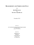
Rosemount 2051 Wireless Pressure Transmitters
Pressure, Level, and Flow Solutions with WirelessHART™
Protocol
Reference Manual
00809-0100-4102, Rev AA
Rosemount 2051 Wireless Pressure, Flow,
and Level Solutions
Read this manual before working with the product. For personal and system safety, and for
optimum product performance, make sure you thoroughly understand the contents before
installing, using, or maintaining this product.
For technical assistance, contacts are listed below:
Customer Central
Technical support, quoting, and order-related questions.
United States - 1-800-999-9307 (7:00 am to 7:00 pm CST)
Asia Pacific- 65 777 8211
Europe/ Middle East/ Africa - 49 (8153) 9390
North American Response Center
Equipment service needs.
1-800-654-7768 (24 hours—includes Canada)
Outside of these areas, contact your local Emerson Process Management representative.
The products described in this document are NOT designed for nuclear-qualified
applications. Using non-nuclear qualified products in applications that require
nuclear-qualified hardware or products may cause inaccurate readings.
For information on Emerson Process Management nuclear-qualified products, contact your
local Rosemount Sales Representative.
i
Reference Manual
00809-0100-4102, Rev AA
Explosions could result in death or serious injury:
Installation of this transmitter in an explosive environment must be in accordance with the
appropriate local, national, and international standards, codes, and practices. Please review
the approvals section of the 2051 reference manual for any restrictions associated with a
safe installation.
Before connecting a HART-based communicator in an explosive atmosphere, make
sure the instruments in the loop are installed in accordance with intrinsically safe or
non-incendive field wiring practices.
This device complies with Part 15 of the FCC Rules. Operation is subject to the following
conditions.
This device may not cause harmful interference. This device must accept any interference
received, including interference that may cause undesired operation.
This device must be installed to ensure a minimum antenna separation distance of 8 in.
(20cm) from all persons.
Process leaks may cause harm or result in death.
To avoid process leaks, only use the o-ring designed to seal with the corresponding
flange adapter.
Electrical shock can result in death or serious injury.
Avoid contact with the leads and the terminals. High voltage that may be present on
leads can cause electrical shock.
The Rosemount 2051 and all other wireless devices should be installed only after the Smart
Wireless Gateway has been installed and is functioning properly. Wireless devices should
also be powered up in order of proximity from the Smart Wireless Gateway, beginning with
the closest. This will result in a simpler and faster network installation.
ii
Reference Manual
00809-0100-4102, Rev AA
Shipping considerations for wireless products (Lithium Batteries: Green Power Module,
model number 701PGNKF):
The unit was shipped to you without the Power Module installed. Please remove the
Power Module from the unit prior to shipping.
Each power module contains one “D” size primary lithium-thionyl chloride battery.
Primary lithium batteries are regulated in transportation by the U.S. Department of
Transportation, and are also covered by IATA (International Air Transport Association),
ICAO (International Civil Aviation Organization), and ARD (European Ground
Transportation of Dangerous Goods). It is the responsibility of the shipper to ensure
compliance with these or any other local requirements. Please consult current
regulations and requirements before shipping.
The power module with the wireless unit contains one “D” size primary lithium-thionyl
chloride battery (Green Power Module, model number 701PGNKF). Each battery contains
approximately 5.0 grams of lithium. Under normal conditions, the battery materials are
self-contained and are not reactive as long as the battery and the pack integrity are
maintained. Care should be taken to prevent thermal, electrical or mechanical damage.
Contacts should be protected to prevent premature discharge.
Battery hazards remain when cells are discharged.
Power modules should be stored in a clean and dry area. For maximum battery life, storage
temperature should not exceed 30 °C (86 °F).
The Power Module may be replaced in a hazardous area. The Power Module has surface
resistivity greater than one gigaohm and must be properly installed in the wireless device
enclosure. Care must be taken during transportation to and from the point of installation to
prevent electrostatic charge build-up.
Using the Rosemount 2051 Wireless Pressure Transmitter in a manner other than what is
specified by the manufacturer may impair the protection provided by the equipment.
iii
Reference Manual
00809-0100-4102, Rev AA
iv
Reference Manual
Table of Contents
00809-0100-4102, Rev AA
May 2013
Contents
1Section 1: Introduction
1.1 Using this manual. . . . . . . . . . . . . . . . . . . . . . . . . . . . . . . . . . . . . . . . . . . . . . . . . . . . . . . 1
1.2 Models covered . . . . . . . . . . . . . . . . . . . . . . . . . . . . . . . . . . . . . . . . . . . . . . . . . . . . . . . . 1
1.2.1 Rosemount 2051C Coplanar™ Pressure Transmitter . . . . . . . . . . . . . . . . . . . 1
1.2.2 Rosemount 2051T in-line Pressure Transmitter . . . . . . . . . . . . . . . . . . . . . . . 1
1.2.3 Rosemount 2051L Level Transmitter . . . . . . . . . . . . . . . . . . . . . . . . . . . . . . . . 2
1.2.4 Rosemount 2051CF Flowmeters . . . . . . . . . . . . . . . . . . . . . . . . . . . . . . . . . . . . 2
1.3 WirelessHART installation flowchart . . . . . . . . . . . . . . . . . . . . . . . . . . . . . . . . . . . . . . 3
1.4 Transmitter overview . . . . . . . . . . . . . . . . . . . . . . . . . . . . . . . . . . . . . . . . . . . . . . . . . . . 4
1.5 Considerations before transmitter installation. . . . . . . . . . . . . . . . . . . . . . . . . . . . . . 5
1.5.1 Wireless considerations. . . . . . . . . . . . . . . . . . . . . . . . . . . . . . . . . . . . . . . . . . . . 5
1.5.2 Mechanical . . . . . . . . . . . . . . . . . . . . . . . . . . . . . . . . . . . . . . . . . . . . . . . . . . . . . . . 6
1.5.3 Electrical . . . . . . . . . . . . . . . . . . . . . . . . . . . . . . . . . . . . . . . . . . . . . . . . . . . . . . . . . 6
1.5.4 Environmental . . . . . . . . . . . . . . . . . . . . . . . . . . . . . . . . . . . . . . . . . . . . . . . . . . . . 7
1.6 Service support. . . . . . . . . . . . . . . . . . . . . . . . . . . . . . . . . . . . . . . . . . . . . . . . . . . . . . . . . 7
1.7 Product Recycling/Disposal . . . . . . . . . . . . . . . . . . . . . . . . . . . . . . . . . . . . . . . . . . . . . . 8
2Section 2: Configuration
2.1 Overview . . . . . . . . . . . . . . . . . . . . . . . . . . . . . . . . . . . . . . . . . . . . . . . . . . . . . . . . . . . . . . 9
2.2 Safety messages . . . . . . . . . . . . . . . . . . . . . . . . . . . . . . . . . . . . . . . . . . . . . . . . . . . . . . . . 9
2.3 Required bench top configuration . . . . . . . . . . . . . . . . . . . . . . . . . . . . . . . . . . . . . . .10
2.3.1 Connection diagrams. . . . . . . . . . . . . . . . . . . . . . . . . . . . . . . . . . . . . . . . . . . . .11
2.4 Basic setup. . . . . . . . . . . . . . . . . . . . . . . . . . . . . . . . . . . . . . . . . . . . . . . . . . . . . . . . . . . .11
2.4.1 Set device tag . . . . . . . . . . . . . . . . . . . . . . . . . . . . . . . . . . . . . . . . . . . . . . . . . . .11
2.4.2 Join device to network . . . . . . . . . . . . . . . . . . . . . . . . . . . . . . . . . . . . . . . . . . . .12
2.4.3 Configure update rate . . . . . . . . . . . . . . . . . . . . . . . . . . . . . . . . . . . . . . . . . . . .12
2.4.4 Set process variable units . . . . . . . . . . . . . . . . . . . . . . . . . . . . . . . . . . . . . . . . .13
2.4.5 Remove Power Module . . . . . . . . . . . . . . . . . . . . . . . . . . . . . . . . . . . . . . . . . . .13
2.5 Configure for Pressure. . . . . . . . . . . . . . . . . . . . . . . . . . . . . . . . . . . . . . . . . . . . . . . . . .13
2.5.1 Re-Mapping device variables . . . . . . . . . . . . . . . . . . . . . . . . . . . . . . . . . . . . . .13
2.5.2 Set range points . . . . . . . . . . . . . . . . . . . . . . . . . . . . . . . . . . . . . . . . . . . . . . . . .14
2.5.3 Set transmitter percent of range (transfer function) . . . . . . . . . . . . . . . . . .15
2.6 Configure for Level and Flow . . . . . . . . . . . . . . . . . . . . . . . . . . . . . . . . . . . . . . . . . . . .16
2.6.1 Configuring scaled variable. . . . . . . . . . . . . . . . . . . . . . . . . . . . . . . . . . . . . . . .16
Table of Contents
i
Reference Manual
Table of Contents
00809-0100-4102, Rev AA
May 2013
2.6.2 Re-Mapping device variables . . . . . . . . . . . . . . . . . . . . . . . . . . . . . . . . . . . . . .18
2.6.3 Set range points . . . . . . . . . . . . . . . . . . . . . . . . . . . . . . . . . . . . . . . . . . . . . . . . .19
2.7 Review configuration data . . . . . . . . . . . . . . . . . . . . . . . . . . . . . . . . . . . . . . . . . . . . . .20
2.7.1 Review pressure information . . . . . . . . . . . . . . . . . . . . . . . . . . . . . . . . . . . . . .20
2.7.2 Review device information . . . . . . . . . . . . . . . . . . . . . . . . . . . . . . . . . . . . . . . .20
2.7.3 Review radio information . . . . . . . . . . . . . . . . . . . . . . . . . . . . . . . . . . . . . . . . .21
2.7.4 Review operating parameters . . . . . . . . . . . . . . . . . . . . . . . . . . . . . . . . . . . . .21
2.8 Configuring the LCD display. . . . . . . . . . . . . . . . . . . . . . . . . . . . . . . . . . . . . . . . . . . . .22
2.9 Detailed transmitter setup . . . . . . . . . . . . . . . . . . . . . . . . . . . . . . . . . . . . . . . . . . . . . .23
2.9.1 Configure process alerts . . . . . . . . . . . . . . . . . . . . . . . . . . . . . . . . . . . . . . . . . .23
2.9.2 Damping. . . . . . . . . . . . . . . . . . . . . . . . . . . . . . . . . . . . . . . . . . . . . . . . . . . . . . . .23
2.9.3 Write protect . . . . . . . . . . . . . . . . . . . . . . . . . . . . . . . . . . . . . . . . . . . . . . . . . . . .24
2.10Diagnostics and service . . . . . . . . . . . . . . . . . . . . . . . . . . . . . . . . . . . . . . . . . . . . . . . .24
2.10.1Device reset . . . . . . . . . . . . . . . . . . . . . . . . . . . . . . . . . . . . . . . . . . . . . . . . . . . . .25
2.10.2Join status. . . . . . . . . . . . . . . . . . . . . . . . . . . . . . . . . . . . . . . . . . . . . . . . . . . . . . .25
2.10.3Number of available neighbors . . . . . . . . . . . . . . . . . . . . . . . . . . . . . . . . . . . .26
2.11Advanced Functions for HART Protocol. . . . . . . . . . . . . . . . . . . . . . . . . . . . . . . . . . .27
2.11.1Saving, Recalling, and Cloning Configuration Data . . . . . . . . . . . . . . . . . . .27
3Section 3: Installation
3.1 Overview . . . . . . . . . . . . . . . . . . . . . . . . . . . . . . . . . . . . . . . . . . . . . . . . . . . . . . . . . . . . .29
3.2 Safety messages . . . . . . . . . . . . . . . . . . . . . . . . . . . . . . . . . . . . . . . . . . . . . . . . . . . . . . .29
3.2.1 Warnings (). . . . . . . . . . . . . . . . . . . . . . . . . . . . . . . . . . . . . . . . . . . . . . . . . . . . . .30
3.3 Considerations . . . . . . . . . . . . . . . . . . . . . . . . . . . . . . . . . . . . . . . . . . . . . . . . . . . . . . . .31
3.3.1 Installation considerations . . . . . . . . . . . . . . . . . . . . . . . . . . . . . . . . . . . . . . . .31
3.3.2 Wireless considerations. . . . . . . . . . . . . . . . . . . . . . . . . . . . . . . . . . . . . . . . . . .31
3.3.3 Mechanical considerations . . . . . . . . . . . . . . . . . . . . . . . . . . . . . . . . . . . . . . . .32
3.3.4 Environmental considerations . . . . . . . . . . . . . . . . . . . . . . . . . . . . . . . . . . . . .32
3.3.5 Draft range considerations . . . . . . . . . . . . . . . . . . . . . . . . . . . . . . . . . . . . . . . .33
3.4 Installation procedures . . . . . . . . . . . . . . . . . . . . . . . . . . . . . . . . . . . . . . . . . . . . . . . . .35
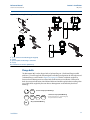
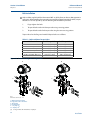
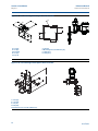
3.4.1 Mount the transmitter . . . . . . . . . . . . . . . . . . . . . . . . . . . . . . . . . . . . . . . . . . . .36
3.4.2 Impulse piping. . . . . . . . . . . . . . . . . . . . . . . . . . . . . . . . . . . . . . . . . . . . . . . . . . .41
3.4.3 Process connections. . . . . . . . . . . . . . . . . . . . . . . . . . . . . . . . . . . . . . . . . . . . . .43
3.4.4 Inline process connection . . . . . . . . . . . . . . . . . . . . . . . . . . . . . . . . . . . . . . . . .44
3.4.5 Power Module installation. . . . . . . . . . . . . . . . . . . . . . . . . . . . . . . . . . . . . . . . .45
3.4.6 Installing the LCD display . . . . . . . . . . . . . . . . . . . . . . . . . . . . . . . . . . . . . . . . .46
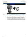
3.5 Rosemount 304, 305 and 306 integral manifolds . . . . . . . . . . . . . . . . . . . . . . . . . .47
ii
Table of Contents
Reference Manual
Table of Contents
00809-0100-4102, Rev AA
May 2013
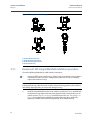
3.5.1 Rosemount 305 Integral Manifold installation procedure . . . . . . . . . . . . .48
3.5.2 Rosemount 306 Integral Manifold installation procedure . . . . . . . . . . . . .49
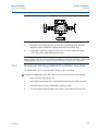
3.5.3 Rosemount 304 Conventional Manifold installation procedure . . . . . . . .50
3.5.4 Manifold operation. . . . . . . . . . . . . . . . . . . . . . . . . . . . . . . . . . . . . . . . . . . . . . .50
4Section 4: Commissioning
4.1 Overview . . . . . . . . . . . . . . . . . . . . . . . . . . . . . . . . . . . . . . . . . . . . . . . . . . . . . . . . . . . . .55
4.2 Safety messages . . . . . . . . . . . . . . . . . . . . . . . . . . . . . . . . . . . . . . . . . . . . . . . . . . . . . . .55
4.2.1 Warnings (). . . . . . . . . . . . . . . . . . . . . . . . . . . . . . . . . . . . . . . . . . . . . . . . . . . . . .56
4.3 Viewing network status . . . . . . . . . . . . . . . . . . . . . . . . . . . . . . . . . . . . . . . . . . . . . . . .57
4.4 Verifying operation . . . . . . . . . . . . . . . . . . . . . . . . . . . . . . . . . . . . . . . . . . . . . . . . . . . .57
4.4.1 Using the Field Communicator. . . . . . . . . . . . . . . . . . . . . . . . . . . . . . . . . . . . .60
4.5 Configuring transmitter security. . . . . . . . . . . . . . . . . . . . . . . . . . . . . . . . . . . . . . . . .61
5Section 5: Operation and maintenance
5.1 Overview . . . . . . . . . . . . . . . . . . . . . . . . . . . . . . . . . . . . . . . . . . . . . . . . . . . . . . . . . . . . .63
5.2 Safety messages . . . . . . . . . . . . . . . . . . . . . . . . . . . . . . . . . . . . . . . . . . . . . . . . . . . . . . .63
5.3 Calibration overview . . . . . . . . . . . . . . . . . . . . . . . . . . . . . . . . . . . . . . . . . . . . . . . . . . .63
5.3.1 Determining necessary Sensor Trims . . . . . . . . . . . . . . . . . . . . . . . . . . . . . . .64
5.3.2 Determining calibration frequency . . . . . . . . . . . . . . . . . . . . . . . . . . . . . . . . .65
5.3.3 Compensating for Span line pressure effects (range 4 and range 5). . . . .66
5.4 Trim the pressure signal . . . . . . . . . . . . . . . . . . . . . . . . . . . . . . . . . . . . . . . . . . . . . . . .67
5.4.1 Sensor Trim Overview . . . . . . . . . . . . . . . . . . . . . . . . . . . . . . . . . . . . . . . . . . . .67
5.4.2 Sensor Trim . . . . . . . . . . . . . . . . . . . . . . . . . . . . . . . . . . . . . . . . . . . . . . . . . . . . .68
5.4.3 Recall Factory Trim—Sensor Trim. . . . . . . . . . . . . . . . . . . . . . . . . . . . . . . . . . .70
5.4.4 Line Pressure Effect (Range 2 and Range 3) . . . . . . . . . . . . . . . . . . . . . . . . . .70
5.4.5 Compensating for Line Pressure (Range 4 and Range 5) . . . . . . . . . . . . . . .70
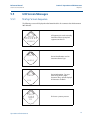
5.5 LCD Screen Messages . . . . . . . . . . . . . . . . . . . . . . . . . . . . . . . . . . . . . . . . . . . . . . . . . .73
5.5.1 Startup Screen Sequence . . . . . . . . . . . . . . . . . . . . . . . . . . . . . . . . . . . . . . . . .73
5.5.2 Diagnostic Button Screen Sequence . . . . . . . . . . . . . . . . . . . . . . . . . . . . . . . .75
5.5.3 Network Diagnostic Status Screens. . . . . . . . . . . . . . . . . . . . . . . . . . . . . . . . .76
5.5.4 Device Diagnostic Screens . . . . . . . . . . . . . . . . . . . . . . . . . . . . . . . . . . . . . . . .79
6Section 6: Troubleshooting
6.1 Overview . . . . . . . . . . . . . . . . . . . . . . . . . . . . . . . . . . . . . . . . . . . . . . . . . . . . . . . . . . . . .83
6.2 Safety messages . . . . . . . . . . . . . . . . . . . . . . . . . . . . . . . . . . . . . . . . . . . . . . . . . . . . . . .83
6.2.1 Warnings (). . . . . . . . . . . . . . . . . . . . . . . . . . . . . . . . . . . . . . . . . . . . . . . . . . . . . .84
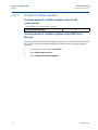
6.3 Removing from service . . . . . . . . . . . . . . . . . . . . . . . . . . . . . . . . . . . . . . . . . . . . . . . . .88
Table of Contents
iii
Reference Manual
Table of Contents
00809-0100-4102, Rev AA
May 2013
AAppendix A: Specifications and
Reference Data
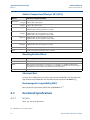
A.1 Performance Specifications . . . . . . . . . . . . . . . . . . . . . . . . . . . . . . . . . . . . . . . . . . . . .89
A.1.1 Conformance to specification (±3s (Sigma)) . . . . . . . . . . . . . . . . . . . . . . . . .89
A.1.2 Digital output . . . . . . . . . . . . . . . . . . . . . . . . . . . . . . . . . . . . . . . . . . . . . . . . . . .89
A.2 Functional Specifications . . . . . . . . . . . . . . . . . . . . . . . . . . . . . . . . . . . . . . . . . . . . . . .92
A.2.1 Service. . . . . . . . . . . . . . . . . . . . . . . . . . . . . . . . . . . . . . . . . . . . . . . . . . . . . . . . . .92
A.2.2 Range and Sensor Limits . . . . . . . . . . . . . . . . . . . . . . . . . . . . . . . . . . . . . . . . . .93
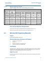
A.3 Wireless Self-Organizing Networks. . . . . . . . . . . . . . . . . . . . . . . . . . . . . . . . . . . . . . .93
A.3.1 Overpressure limits . . . . . . . . . . . . . . . . . . . . . . . . . . . . . . . . . . . . . . . . . . . . . .94
A.3.2 Static pressure limit . . . . . . . . . . . . . . . . . . . . . . . . . . . . . . . . . . . . . . . . . . . . . .95
A.3.3 Burst pressure limits. . . . . . . . . . . . . . . . . . . . . . . . . . . . . . . . . . . . . . . . . . . . . .95
A.3.4 Temperature limits. . . . . . . . . . . . . . . . . . . . . . . . . . . . . . . . . . . . . . . . . . . . . . .95
A.3.5 Humidity Limits. . . . . . . . . . . . . . . . . . . . . . . . . . . . . . . . . . . . . . . . . . . . . . . . . .96
A.3.6 Volumetric Displacement . . . . . . . . . . . . . . . . . . . . . . . . . . . . . . . . . . . . . . . . .96
A.3.7 Damping. . . . . . . . . . . . . . . . . . . . . . . . . . . . . . . . . . . . . . . . . . . . . . . . . . . . . . . .96
A.4 Physical specifications . . . . . . . . . . . . . . . . . . . . . . . . . . . . . . . . . . . . . . . . . . . . . . . . . .97
A.4.1 Electrical connections . . . . . . . . . . . . . . . . . . . . . . . . . . . . . . . . . . . . . . . . . . . .97
A.4.2 Process connections. . . . . . . . . . . . . . . . . . . . . . . . . . . . . . . . . . . . . . . . . . . . . .97
A.4.3 Process-Wetted parts. . . . . . . . . . . . . . . . . . . . . . . . . . . . . . . . . . . . . . . . . . . . .97
A.4.4 Rosemount 2051L Process Wetted Parts . . . . . . . . . . . . . . . . . . . . . . . . . . . .98
A.4.5 Non-Wetted Parts. . . . . . . . . . . . . . . . . . . . . . . . . . . . . . . . . . . . . . . . . . . . . . . .98
A.4.6 Shipping Weights for 2051 Wireless Pressure Transmitter. . . . . . . . . . . 100
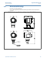
A.5 Dimensional Drawings . . . . . . . . . . . . . . . . . . . . . . . . . . . . . . . . . . . . . . . . . . . . . . . 101
A.6 Ordering Information . . . . . . . . . . . . . . . . . . . . . . . . . . . . . . . . . . . . . . . . . . . . . . . . 103
A.7 Options . . . . . . . . . . . . . . . . . . . . . . . . . . . . . . . . . . . . . . . . . . . . . . . . . . . . . . . . . . . . 127
A.8 Spare parts. . . . . . . . . . . . . . . . . . . . . . . . . . . . . . . . . . . . . . . . . . . . . . . . . . . . . . . . . . 130
BAppendix B: Product Certifications
B.1 Wireless Certifications. . . . . . . . . . . . . . . . . . . . . . . . . . . . . . . . . . . . . . . . . . . . . . . . 131
B.1.1 Approved manufacturing locations. . . . . . . . . . . . . . . . . . . . . . . . . . . . . . . 131
B.1.2 European directive information . . . . . . . . . . . . . . . . . . . . . . . . . . . . . . . . . . 131
B.1.3 Telecommunication compliance . . . . . . . . . . . . . . . . . . . . . . . . . . . . . . . . . 131
B.1.4 FCC and IC . . . . . . . . . . . . . . . . . . . . . . . . . . . . . . . . . . . . . . . . . . . . . . . . . . . . 131
B.1.5 Ordinary location certification for FM . . . . . . . . . . . . . . . . . . . . . . . . . . . . . 132
B.1.6 North American certifications . . . . . . . . . . . . . . . . . . . . . . . . . . . . . . . . . . . 132
B.1.7 CSA - Canadian Standards Association . . . . . . . . . . . . . . . . . . . . . . . . . . . . 132
B.1.8 European certifications . . . . . . . . . . . . . . . . . . . . . . . . . . . . . . . . . . . . . . . . . 132
iv
Table of Contents
Reference Manual
Table of Contents
00809-0100-4102, Rev AA
May 2013
CAppendix C: Field Communicator Menu Trees and Fast Keys
C.1 Field Communicator menu trees. . . . . . . . . . . . . . . . . . . . . . . . . . . . . . . . . . . . . . . 135
DAppendix D: Network design best practices
D.1 Effective range . . . . . . . . . . . . . . . . . . . . . . . . . . . . . . . . . . . . . . . . . . . . . . . . . . . . . . 139
Table of Contents
v
Table of Contents
May 2013
vi
Reference Manual
00809-0100-4102, Rev AA
Table of Contents
Reference Manual
Section 1: Introduction
00809-0100-4102, Rev AA
Section 1
May 2013
Introduction
Using this manual . . . . . . . . . . . . . . . . . . . . . . . . . . . . . . . . . . . . . . . . . . . . . . . . . . . . . . . . page 1
Models covered . . . . . . . . . . . . . . . . . . . . . . . . . . . . . . . . . . . . . . . . . . . . . . . . . . . . . . . . . . page 1
Service support . . . . . . . . . . . . . . . . . . . . . . . . . . . . . . . . . . . . . . . . . . . . . . . . . . . . . . . . . . page 7
Product Recycling/Disposal . . . . . . . . . . . . . . . . . . . . . . . . . . . . . . . . . . . . . . . . . . . . . . . page 8
1.1
Using this manual
The sections in this manual provide information on installing, operating, and maintaining the
Rosemount 2051 Wireless pressure transmitter with WirelessHART™ protocol. The sections are
organized as follows:
1.2
Section 2: Configuration provides instruction on commissioning and operating 2051
Wireless transmitters. Information on software functions, configuration parameters,
and online variables is also included.
Section 3: Installation contains mechanical and electrical installation instructions.
Section 4: Commissioning contains techniques for properly commissioning the device.
Section 5: Operation and maintenance contains operation and maintenance
techniques.
Section 6: Troubleshooting provides troubleshooting techniques for the most common
operating problems.
Appendix A: Specifications and Reference Data supplies reference and specification
data, as well as ordering information.
Appendix B: Product Certifications contains approval information.
Appendix C: Field Communicator Menu Trees and Fast Keys provides full menu trees
and abbreviated fast key sequences for commissioning tasks.
Appendix D: Network design best practices provides information on how to optimize
network reliability and performance.
Models covered
The following Rosemount 2051 Pressure Transmitters are covered by this manual:
1.2.1
1.2.2
Rosemount 2051C Coplanar™ Pressure Transmitter
Measures differential and gage pressure up to 2000 psi (137,9 bar).
Measures absolute pressure up to 4000 psi (275,8 bar)
Rosemount 2051T in-line Pressure Transmitter
Introduction
Measures gage/absolute pressure up to 10000 psi (689,5 bar).
1
Reference Manual
Section 1: Introduction
00809-0100-4102, Rev AA
May 2013
1.2.3
Rosemount 2051L Level Transmitter
1.2.4
Rosemount 2051CF Flowmeters
2
Measures level and specific gravity up to 300 psi (20,7 bar)
Measures flow in line sizes from 1/2 in. (15 mm) to 96 in. (2400 mm)
Introduction
Reference Manual
Section 1: Introduction
00809-0100-4102, Rev AA
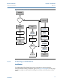
1.3
May 2013
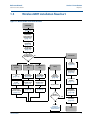
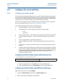
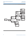
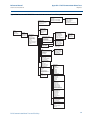
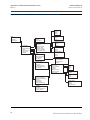
WirelessHART installation flowchart
Figure 1-1. WirelessHART installation flowchart
START HERE
Set Device Tag
(page 11)
Join Device to
Network by
Setting Network
ID and Join Key
(page 12)
Configure
Update Rate
(page 12)
Set Process
Variable Units
(page 13)
Bench
Configuration
and Calibration
Field Install
No
Yes
Configure for
Pressure
Configure for
Level
Configure for
Flow
Mount
Transmitter
(page 36)
Verify
Check Process
Connection
(page 43)
Set Pressure to
PV
(page 13)
Configure
Scaled Variable
(page 16)
Configure
Scaled Variable
(page 16)
Set Range
Points
(page 14)
Set Scaled
Variable to PV
(page 13)
Set Scaled
Variable to PV
(page 13)
Select Transfer
Function for
Percent of Range
(page 15)
Set Range Points
(page 14)
Review
Transmitter
Configuration
(page 20)
Install Power
Module
(page 13)
Apply Pressure
Set Range Points
(page 14)
Confirm
Transmitter
Configuration
(page 20)
Within
Specifications?
Yes
Trim the
Transmitter
(page 67)
No
Refer to
Section 5:
Operation and
maintenance
Introduction
Done
3
Reference Manual
Section 1: Introduction
00809-0100-4102, Rev AA
May 2013
1.4
Transmitter overview
The Rosemount 2051C Coplanar design is offered for Differential Pressure (DP), Gage Pressure
(GP) and Absolute Pressure (AP) measurements. The Rosemount 2051C utilizes capacitance
sensor technology for DP and GP measurements. The Rosemount 2051T and 2051CA utilize
piezo-resistive sensor technology for AP and GP measurements.
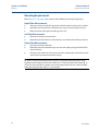
The major components of the Rosemount 2051 Wireless transmitter are the sensor module and
the electronics housing. The sensor module contains the oil filled sensor system (isolating
diaphragms, oil fill system, and sensor) and the sensor electronics. The sensor electronics are
installed within the sensor module and include a temperature sensor, a memory module, and
the analog to digital signal converter (A/D converter). The electrical signals from the sensor
module are transmitted to the output electronics in the electronics housing. The electronics
housing contains the output electronics board, the antenna, and the battery. The basic block
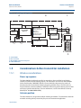
diagram of the Rosemount 2051CD Wireless device is illustrated in Figure 1-3 on page 5.
For the Rosemount 2051, pressure is applied to the isolating diaphragm(s). The oil deflects the
sensor which then changes its capacitance or voltage signal. This signal is then changed to a
digital signal by the Signal Processing Module. The microprocessor then takes the signals from
the Signal Processing Module and calculates the correct output of the transmitter. This signal is
then sent via wireless communication to the Gateway.
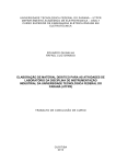
An optional LCD can be ordered that connects directly to the output electronics board which
maintains direct access to the signal terminals. The display indicates output and abbreviated
diagnostic messages. A clear display cover is provided. For WirelessHART output, the LCD
Display features a three-line display. The first line describes the process variable measured, the
second line displays the measured value, and the third line displays engineering units. The LCD
can also display diagnostics messages.
Note
LCD Display utilizes a 3-line, 7-digit character display and can display output and diagnostic
messages. See Figure 1-2.
Figure 1-2. LCD Display
LCD Display
4
Introduction
Reference Manual
Section 1: Introduction
00809-0100-4102, Rev AA
May 2013
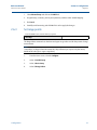
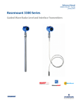
Figure 1-3. Block diagram of operation
A
B
C
Signal Processing
Microprocessor
Temp.
Sensor
Sensor Module
Memory
Sensor linearization
Rerange
Diagnostics
Engineering units
Communication
Local HART
Handheld
Communicator
WirelessHART
Communication
Memory
Configuration
D
A. Sensor Module
B. Electronics Board
C. WirelessHART Signal to Control System
D. Field Communicator
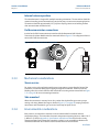
1.5
Considerations before transmitter installation
1.5.1
Wireless considerations
Power up sequence
The Power Module should not be installed on any wireless device until the Smart Wireless
Gateway is installed and functioning properly. This transmitter uses the Green Power Module
(order model number 701PGNKF). Wireless devices should also be powered up in order of
proximity from the Smart Wireless Gateway, beginning with the closest. This will result in a
simpler and faster network installation. Enable Active Advertising on the Gateway to ensure that
new devices join the network faster. For more information, see the Smart Wireless Gateway
Manual (Doc. No. 00809-0200-4420).
Antenna position
The internal antenna is designed for multiple mounting orientations. The transmitter should be
mounted according to best practices for your pressure measurement application.
Introduction
5
Section 1: Introduction
Reference Manual
00809-0100-4102, Rev AA
May 2013
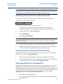
Network design best practices
When mounting the device, recommended practices should be considered to achieve the best
wireless performance. See Appendix D: Network design best practices for more information on
recommended practices.
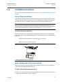
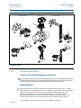
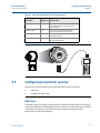
Field communicator connections
The Power Module needs to be installed in the device for the Field Communicator to interface
with the Rosemount 2051. The Field Communicator connections are located on the Power
Module. To communicate to the transmitter, connect the Field Communicator to the COMM
port connections on the Power Module. This transmitter uses the Green Power Module; please
order model number 701PGNKF. Field communication with this device requires a HART-based
Field Communicator using the correct Rosemount 2051 Wireless DD. The Power Module is
keyed and can only be inserted in one orientation. Refer to Figure 1-4 for instructions on
connecting the Field Communicator to the 2051.
Figure 1-4. Field Communicator Connections
1.5.2
Mechanical
Location
When choosing an installation location and position, take into account access to the power
module compartment for easy power module replacement.
Electronics cover
The electronics cover is tightened so that polymer contacts polymer. When removing the
electronics cover, ensure that there is no damage done to the o-ring. If damaged replace before
reattaching cover, ensuring polymer contacts polymer (i.e. no o-ring visible).
1.5.3
Electrical
Power module
The Rosemount 2051 Wireless Pressure Transmitter is self-powered. The Power Module
contains a primary lithium-thionyl chloride battery (Green Power Module, model number
6
Introduction
Reference Manual
Section 1: Introduction
00809-0100-4102, Rev AA
May 2013
701PGNKF). Each battery contains approximately 5 grams of lithium. Under normal conditions,
the battery materials are self-contained and are not reactive as long as the battery and the
Power Module are maintained. Care should be taken to prevent thermal, electrical, or
mechanical damage. Contacts should be protected to prevent premature discharge.
Use caution when handling the Power Module, it may be damaged if dropped from heights in
excess of 6.10 m (20 ft).
1.5.4
Environmental
Verify that the operating atmosphere of the transmitter is consistent with the appropriate
hazardous locations certifications.
Temperature effects
The transmitter will operate within specifications for ambient temperatures between -40 and 85
°C (-40 and 185 °F).
Heat from the process is transferred to the transmitter housing. If the process temperature is
high, the ambient temperature will need to be lower to account for heat transferred to the
transmitter housing. See “Process Temperature Limits” on page 96 for process temperature
derating.
1.6
Service support
Within the United States, call the Emerson Process Management Instrument and Valve
Response Center using the 1-800-654-RSMT (7768) toll-free number. This center, available 24
hours a day, will assist you with any needed information or materials.
The center will ask for product model and serial numbers, and will provide a Return Material
Authorization (RMA) number. The center will also ask for the process material to which the
product was last exposed.
For inquiries outside of the United States, contact the nearest Emerson Process Management
representative for RMA instructions.
To expedite the return process outside of the United States, contact the nearest Emerson
Process Management representative.
Individuals who handle products exposed to a hazardous substance can avoid injury if they
are informed of and understand the hazard. The product being returned will require a copy
of the required Material Safety Data Sheet (MSDS) for each substance must be included
with the returned goods.
Introduction
7
Section 1: Introduction
Reference Manual
00809-0100-4102, Rev AA
May 2013
Shipping considerations for wireless products (Lithium Batteries: Green Power Module,
model number 701PGNKF):
The unit was shipped to you without the Power Module installed. Please remove the Power
Module from the unit prior to shipping.
Each power module contains a primary lithium-thionyl chloride battery. Primary lithium
batteries are regulated in transportation by the U.S. Department of Transportation, and are
also covered by IATA (International Air Transport Association), ICAO (International Civil
Aviation Organization), and ARD (European Ground Transportation of Dangerous Goods). It
is the responsibility of the shipper to ensure compliance with these or any other local
requirements. Please consult current regulations and requirements before shipping.
The Power Module contains a primary lithium-thionyl chloride battery (Green Power Module,
model number 701PGNKF). Each Power Module contains approximately 5 grams of lithium.
Under normal conditions, the Power Module materials are self-contained and are not reactive as
long as the batteries and the module integrity are maintained. Care should be taken to prevent
thermal, electrical or mechanical damage. Contacts should be protected to prevent premature
discharge. Power Module hazards remain when cells are discharged.
Power Module should be stored in a clean and dry area. For maximum battery life, storage
temperature should not exceed 86 °F (30 °C).
Emerson Process Management Instrument and Valve Response Center representatives will
explain the additional information and procedures necessary to return goods exposed to
hazardous substances.
1.7
Product Recycling/Disposal
Recycling of equipment and packaging should be taken into consideration and disposed of in
accordance with local and national legislation/regulations.
8
Introduction
Section 2: Configuration
Reference Manual
May 2013
00809-0100-4102, Rev AA
Section 2
Configuration
Overview . . . . . . . . . . . . . . . . . . . . . . . . . . . . . . . . . . . . . . . . . . . . . . . . . . . . . . . . . . . . . . . page 9
Safety messages . . . . . . . . . . . . . . . . . . . . . . . . . . . . . . . . . . . . . . . . . . . . . . . . . . . . . . . . . page 9
Required bench top configuration . . . . . . . . . . . . . . . . . . . . . . . . . . . . . . . . . . . . . . . . . page 10
Basic setup . . . . . . . . . . . . . . . . . . . . . . . . . . . . . . . . . . . . . . . . . . . . . . . . . . . . . . . . . . . . . . page 11
Review configuration data . . . . . . . . . . . . . . . . . . . . . . . . . . . . . . . . . . . . . . . . . . . . . . . . page 20
Review operating parameters . . . . . . . . . . . . . . . . . . . . . . . . . . . . . . . . . . . . . . . . . . . . . page 21
Review operating parameters . . . . . . . . . . . . . . . . . . . . . . . . . . . . . . . . . . . . . . . . . . . . . page 21
Configuring the LCD display . . . . . . . . . . . . . . . . . . . . . . . . . . . . . . . . . . . . . . . . . . . . . . . page 22
Configuring the LCD display . . . . . . . . . . . . . . . . . . . . . . . . . . . . . . . . . . . . . . . . . . . . . . . page 22
Detailed transmitter setup . . . . . . . . . . . . . . . . . . . . . . . . . . . . . . . . . . . . . . . . . . . . . . . . page 23
Diagnostics and service . . . . . . . . . . . . . . . . . . . . . . . . . . . . . . . . . . . . . . . . . . . . . . . . . . . page 24
Advanced Functions for HART Protocol . . . . . . . . . . . . . . . . . . . . . . . . . . . . . . . . . . . . . page 27
2.1
Overview
This section contains information on commissioning and tasks that should be performed on the
bench prior to installation.
Field Communicator and AMS Device Manager instructions are given to perform configuration
functions. For convenience, Field Communicator fast key sequences are labeled “Fast Keys” for
each software function below the appropriate headings.
Full Field Communicator menu trees and fast key sequences are available in Appendix C: Field
Communicator Menu Trees and Fast Keys.
2.2
Safety messages
Procedures and instructions in this section may require special precautions to ensure the safety
of the personnel performing the operations. Information that raises potential safety issues is
indicated by a warning symbol ( ). Refer to the following safety messages before performing
an operation preceded by this symbol.
Configuration
9
Reference Manual
Section 2: Configuration
00809-0100-4102, Rev AA
May 2013
Warnings ( )
Failure to follow these installation guidelines could result in death or
serious injury.
Make sure only qualified personnel perform the installation.
Explosions could result in death or serious injury:
Installation of this transmitter in an explosive environment must be in accordance with the
appropriate local, national, and international standards, codes, and practices. Please review
the approvals section of the 2051 Wireless reference manual for any restrictions associated
with a safe installation.
Before connecting a Field Communicator in an explosive atmosphere, make sure the
instruments are installed in accordance with intrinsically safe or non-incendive field
wiring practices.
Verify that the operating atmosphere of the transmitter is consistent with the
appropriate hazardous locations certifications
Process leaks could result in death or serious injury.
Install and tighten process connectors before applying pressure.
Electrical shock could cause death or serious injury.
Avoid contact with the leads and terminals. High voltage that may be present on leads
can cause electrical shock.
This device complies with Part 15 of the FCC Rules. Operation is subject to the following
conditions: This device may not cause harmful interference. This device must accept any
interference received, including interference that may cause undesired operation.
2.3
This device must be installed to ensure a minimum antenna separation distance of
20cm (8 in.) from all persons.
Required bench top configuration
Bench top configuration requires a Field Communicator, AMS, or any WirelessHART
Communicator. Connect the Field Communicator leads to the terminals labeled “COMM” on the
Power Module. See Figure 2-1 on page 11.
Bench top configuration consists of testing the transmitter and verifying transmitter
configuration data. 2051 Wireless transmitters must be configured before installation.
Configuring the transmitter on the bench before installation using a Field Communicator, AMS,
or any WirelessHART Communicator ensures that all network settings are working correctly.
When using a Field Communicator, any configuration changes made must be sent to the
transmitter by using the “Send” key (F2). AMS configuration changes are implemented when
the “Apply” button is clicked.
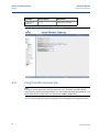
AMS Wireless Configurator
AMS is capable of connecting to devices either directly, using a HART modem, or wirelessly via
the Smart Wireless Gateway. When configuring the device, double click the device icon or right
click and select Configure.
10
Configuration
Reference Manual
Section 2: Configuration
00809-0100-4102, Rev AA
2.3.1
May 2013
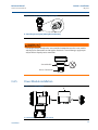
Connection diagrams
Bench hook-up
Connect the bench equipment as shown in Figure 2-1 on page 11, and turn on the Field
Communicator by pressing the ON/OFF key or log into AMS. The Field Communicator or AMS
will search for a HART-compatible device and indicate when the connection is made. If the Field
Communicator or AMS fail to connect, it indicates that no device was found. If this occurs, refer
to Section 6: Troubleshooting.
Field hook-up
Figure 2-1 on page 11 illustrates the wiring for a field hook-up with a Field Communicator or
AMS. The Field Communicator or AMS may be connected at “COMM” on the transmitter Power
Module.
Figure 2-1. Field Communicator Connection
For HART communication, a 2051 WirelessHART DD is required.
2.4
Basic setup
2.4.1
Set device tag
Fast Keys
2, 2, 9, 1, 1
The tag is used to identify the device. You can use an 8 to 32 character tag.
Configuration
1.
From the Home screen, select 2: Configure
2.
Select 2: Manual Setup
3.
Select 9: Device Information
4.
Select 1: Identification
5.
Select 1: Tag
11
Reference Manual
Section 2: Configuration
00809-0100-4102, Rev AA
May 2013
2.4.2
Join device to network
Fast Keys
2, 1, 3
In order to communicate with the Smart Wireless Gateway, and ultimately the Host System, the
transmitter must be configured to communicate over the wireless network. This step is the
wireless equivalent of connecting wires from a transmitter to the host system.
1.
From the Home screen, select 2: Configure.
2.
Select 1: Guided Setup.
3.
Select 3: Join Device to Network.
Using a Field Communicator or AMS, enter the Network ID and Join Key so that they match the
Network ID and Join Key of the Smart Wireless Gateway and other devices in the network. If the
Network ID and Join Key are not identical to those set in the Gateway, the transmitter will not
communicate with the network. The Network ID and Join Key may be obtained from the Smart
Wireless Gateway on the Setup>Network>Settings page on the web server.
2.4.3
Configure update rate
Fast Keys
2, 1, 4
The Update Rate is the frequency at which a new measurement is taken and transmitted over
the wireless network. This by default is 1 minute. This may be changed at commissioning, or at
any time via AMS Wireless Configurator. The Update Rate is user selectable from 1 second to 60
minutes.
12
1.
From the Home screen, select 2: Configure.
2.
Select 1: Guided Setup.
3.
Select 4: Configure Update Rate.
Configuration
Reference Manual
Section 2: Configuration
00809-0100-4102, Rev AA
2.4.4
May 2013
Set process variable units
Fast Keys
2, 2, 2, 3
The PV Unit command sets the process variable units to allow you to monitor your process using
the appropriate units of measure.
To select a unit of measure for the PV:
1.
From the Home screen, select 2: Configure.
2.
Select 2: Manual Setup.
3.
Select 2: Pressure.
4.
Select 3: Unit to select from the following engineering units:
2.4.5
inH2O at 4 °C
inH2O at 60 °F
inH2O at 68 °F
ftH2O at 4 °C
ftH2O at 60 °F
ftH2O at 68 °F
mmH2O at 4 °C
mmH2O at 68 °F
cmH2O at 4 °C
mH2O at 4 °C
inHg at 0 °C
mmHg at 0 °C
cmHg at 0 °C
mHg at 0 °C
mmHg
Psi
Atm
Torr
Pascals
hectoPascals
Kilopascals
Mpa
Bar
Mbar
g/cm2
kg/cm2
kg/m2
Remove Power Module
After the sensor and network have been configured, remove the Power Module and replace the
housing cover. The Power Module should be inserted only when the device is ready to be
commissioned.
Use caution when handling the Power Module. The Power Module may be damaged if dropped
from heights in excess of 6.10 m (20 ft).
2.5
Configure for Pressure
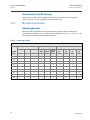
2.5.1
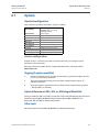
Re-Mapping device variables
The re-mapping function allows the transmitter primary, secondary, tertiary, and quaternary
variables (PV, SV, TV, and QV) to be configured in one of two configurations. The user may select
either the option of Classic mapping or Scaled Variable Mapping, see Table 2-1 for what is
mapped to each variable. All variables can be remapped with a Field Communicator or AMS
Device Manager.
Configuration
13
Reference Manual
Section 2: Configuration
00809-0100-4102, Rev AA
May 2013
Table 2-1. Variable Mapping
Classic Mapping
Scaled Variable Mapping
PV
Pressure
Scaled Variable
SV
Sensor Temperature
Pressure
TV
Electronics Temperature
Sensor Temperature
QV
Supply Voltage
Supply Voltage
Note
The variable assigned to the primary variable drives the output. This value can be selected as
Pressure or Scaled Variable.
Re-mapping using a Field Communicator
From the HOME screen, enter the fast key sequence
Fast Keys
2, 2, 6, 1
Re-mapping using AMS Device Manager
Right click on the device and select Configure.
1.
Select Manual Setup and click on the HART tab.
2. Assign Primary, secondary, tertiary and quaternary variables under Variable Mapping.
3. Click Send.
4. Carefully read the warning and click Yes if it is safe to apply the changes.
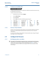
2.5.2
Set range points
From the HOME screen, enter the fast key sequence
Fast Keys
2, 1, 1, 5
The Range Values command sets the lower and upper range values used for the percent of range
measurement.
Note
Transmitters are shipped from Rosemount Inc. fully calibrated per request or by the factory
default of full scale (span = upper range limit).
14
1.
From the Home screen, select 2: Configure
2.
Select 1: Guided Setup
3.
Select 1: Basic Setup
4.
Select 5: Range Values
Configuration
Reference Manual
Section 2: Configuration
00809-0100-4102, Rev AA
2.5.3
May 2013
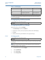
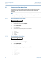
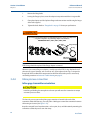
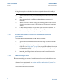
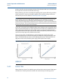
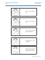
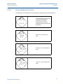
Set transmitter percent of range (transfer function)
The Rosemount 2051 Wireless transmitter has two transfer functions for pressure applications:
Linear and Square Root. As shown in Figure 2-2 on page 15, activating the square root options
the transmitter analog output proportional to flow.
However, for DP Flow and DP Level applications it is recommended to use Scaled Variable. Refer
to “Diagnostics and service” on page 24 for setup instructions.
From 0 to 0.6 percent of the ranged pressure input, the slope of the curve is unity (y = x). This
allows accurate calibration near zero. Greater slopes would cause large changes in output (for
small changes at input). From 0.6 percent to 0.8 percent, curve slope equals 42 (y = 42x) to
achieve continuous transition from linear to square root at the transition point.
Setting transmitter output with a Field Communicator
From the HOME screen, enter the fast key sequence
2, 2, 4, 2
Fast Keys
Setting transmitter output with AMS Device Manager
Right click on the device and select Configure.
1.
Click Manual Setup and choose output type from Transfer Function and click Send.
2.
Carefully read the warning and click Yes if it is safe to apply the changes.
Figure 2-2. Square Root Output Transition Point
Full Scale
Flow (%)
Sq. Root
Curve
Sq. Root Curve
Transition Point
Transition Point
Linear Section
Slope=42
Slope=1
Configuration
15
Reference Manual
Section 2: Configuration
00809-0100-4102, Rev AA
May 2013
2.6
Configure for Level and Flow
2.6.1
Configuring scaled variable
The Scaled Variable configuration allows the user to create a relationship/conversion between
the pressure units and user-defined/custom units. There are two use cases for Scaled Variable.
The first use case is to allow custom units to be displayed on the transmitter's LCD Display. The
second use case is to allow custom units to drive the transmitter's PV output.
If the user desires custom units to drive the PV output, Scaled Variable must be re-mapped as
the primary variable. Refer to “Re-Mapping device variables” on page 18.
The Scaled Variable configuration defines the following items:
Scaled Variable units - Custom units to be displayed.
Scaled data options - Defines the transfer function for the application
–
Linear
–
Square root
Pressure value position 1 - Lower known value point with consideration of linear offset.
Scaled Variable value position 1 - Custom unit equivalent to the lower known value
point.
Pressure value position 2 - Upper known value point
Scaled Variable value position 2 - Custom unit equivalent to the upper known value
point
Linear offset - The value required to zero out pressures affecting the desired pressure
reading.
Low flow cutoff - Point at which output is driven to zero to prevent problems caused by
process noise. It is highly recommended to use the low flow cutoff function in order to
have a stable output and avoid problems due to process noise at a low flow or no flow
condition. A low flow cutoff value that is practical for the flow element in the
application should be entered.
Configuring Scaled Variable using a Field Communicator
From the HOME screen, enter the fast key sequence
Device Dashboard Fast Keys
1.
2, 1, 7
Follow the screen prompts to configure Scaled Variable.
a.
When configuring for level, select Linear under Select Scaled data options.
b. When configuring for flow, select Square Root under Select Scaled data options.
Configuring Scaled Variable using AMS Device Manager
Right click on the device and, select Configure.
1.
Select the Scaled Variable tab and click the Scaled Variable button.
2. Follow screen prompts to configure Scaled Variable
16
Configuration
Reference Manual
Section 2: Configuration
00809-0100-4102, Rev AA
May 2013
a.
When configuring for level applications, select Linear under Select Scaled data options.
b. When configuring for flow applications, select Square Root under Select Scaled data
options.
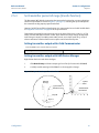
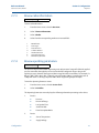
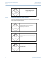
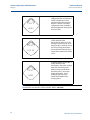
DP Level Example
Figure 2-3. Example tank
A
D
B
H
L
C
A. 230 in.
B. 200 in.
C. 12 in.
D. 0.94 sg
A differential transmitter is used in a level application. Once installed on an empty tank and taps
vented, the process variable reading is -209.4 inH2O. The process variable reading is the head
pressure created by fill fluid in the capillary. Based on Table 2-2 on page 2-17, the Scaled
Variable configuration would be as follows:
Table 2-2. Scaled Variable Configuration for Tank Application
Scaled Variable units:
inch
Scaled data options:
linear
Pressure value position 1:
0 inH2O
Scaled Variable position 1:
12 in.
Pressure value position 2:
188 inH2O
Scaled Variable position 2:
212 in.
Linear offset:
-209.4 inH2O
DP Flow example
Configuration
A differential pressure transmitter is used in conjunction with an orifice plate in a flow
application where the differential pressure at full scale flow is 125 inH2O. In this particular
application, the flow rate at full scale flow is 20,000 gallons of water per hour. It is highly
17
Reference Manual
Section 2: Configuration
00809-0100-4102, Rev AA
May 2013
recommended to use the low flow cutoff function in order to have a stable output and avoid
problems due to process noise at a low flow or no flow condition. A low flow cutoff value that is
practical for the flow element in the application should be entered. In this particular example,
the low flow cutoff value is 1000 gallons of water per hour. Based on this information, the Scaled
Variable configuration would be as follows:
Table 2-3. Scaled Variable Configuration for Flow Application
Scaled Variable units:
gal/h
Scaled data options:
square root
Pressure value position 2:
125 inH2O
Scaled Variable position 2:
20,000 gal/h
Low Flow Cutoff:
1000 gal/h
Note
Pressure value position 1 and Scaled Variable position 1 are always set to zero for a flow
application. No configuration of these values is required.
2.6.2
Re-Mapping device variables
The re-mapping function allows the transmitter primary, secondary, tertiary, and quaternary
variables (PV, SV, TV, and QV) to be configured in one of two configurations. The user may select
either the option of Classic Mapping or Scaled Variable Mapping, see Table 2-4 for what is
mapped to each variable. All variables can be remapped with a Field Communicator or AMS
Device Manager.
Table 2-4. Variable Mapping
Classic Mapping
Scaled Variable Mapping
PV
Pressure
Scaled Variable
SV
Sensor Temperature
Pressure
TV
Electronics Temperature
Sensor Temperature
QV
Supply Voltage
Supply Voltage
Note
The variable assigned to the primary variable drives the output. This value can be selected as
Pressure or Scaled Variable.
Re-mapping using a Field Communicator
From the HOME screen, enter the fast key sequence
Fast Keys
2, 2, 6, 1, 1
Re-mapping using AMS Device Manager
Right click on the device and select Configure.
18
Configuration
Reference Manual
Section 2: Configuration
00809-0100-4102, Rev AA
1.
May 2013
Select Manual Setup and click on the HART tab.
2. Assign Primary, secondary, tertiary and quaternary variables under Variable Mapping.
3. Click Send.
4. Carefully read the warning and click Yes if it is safe to apply the changes.
2.6.3
Set range points
From the HOME screen, enter the fast key sequence
Fast Keys
2, 1, 1, 5
The Range Values command sets the lower and upper range values used for the percent of range
measurement.
Note
Transmitters are shipped from Rosemount Inc. fully calibrated per request or by the factory
default of full scale (span = upper range limit).
Configuration
1.
From the Home screen, select 2: Configure
2.
Select 1: Guided Setup
3.
Select 1: Basic Setup
4.
Select 5: Range Values
19
Reference Manual
Section 2: Configuration
00809-0100-4102, Rev AA
May 2013
2.7
Review configuration data
The following is a list of factory default configurations that can be viewed by using the Field
Communicator or AMS. Follow the steps below to review the transmitter configuration
information.
Note
Information and procedures in this section that make use of Field Communicator fast key
sequences and AMS assume that the transmitter and communication equipment are
connected, powered, and operating correctly.
2.7.1
Review pressure information
Fast Keys
2, 2, 2
To view pressure information:
1.
From the Home screen, select 2: Configure.
2.
Select 2: Manual Setup.
3.
Select 2: Pressure.
4.
Select from the corresponding number to view each field:
1
2
3
4
2.7.2
Pressure
Pressure Status
Units
Damping
Review device information
Fast Keys
2, 2, 9
To view device information:
1.
From the Home screen, select 2: Configure.
2.
Select 2: Manual Setup.
3.
Select 9: Device Information.
4.
Select from the corresponding number to view each field:
1
2
3
4
5
6
20
Identification
Revisions
Radio
Sensor Information
Flange Information
Remote Seal
Configuration
Reference Manual
Section 2: Configuration
00809-0100-4102, Rev AA
2.7.3
May 2013
Review radio information
Fast Keys
1, 7, 3
To view radio information:
1.
From the Home screen, select 1: Overview.
2.
Select 7: Device Information.
3.
Select 3: Radio.
4.
Select from the corresponding number to view each field:
1
2
3
4
5
6
7
2.7.4
Manufacturer
Device Type
Device Revision
Software Revision
Hardware Revision
Transmit Power Level
Minimum Update Rate
Review operating parameters
Fast Keys
3, 2
The pressure output value in both engineering units and percent of range will reflect the applied
pressure even when the applied pressure is outside of the configured range as long as the
applied pressure is between the upper and lower range limit of the transmitter. For example, if a
Range 2 2051T (LRL = 0 psi, URL = 150 psi) is ranged from 0 to 100 psi, an applied pressure of
150 psi will return a % of range output of 150% and an engineering output of 150 psi.
To view the Operating Parameters menu:
1.
From the Home screen, select 3: Service Tools.
2.
Select 2: Variables.
The Operating Parameters menu displays the following information pertaining to the device:
1.
2.
Configuration
Process
Pressure
Percent of Range
Last Update Time
Scaled Variable
Enter Fast Update Mode
Device
Sensor Temperature
Supply Voltage
21
Reference Manual
Section 2: Configuration
00809-0100-4102, Rev AA
May 2013
2.8
Configuring the LCD display
The LCD Display configuration command allows customization of the LCD to suit application
requirements. The LCD will alternate between the selected items.
Pressure Units
Sensor Temperature
% of Range
Supply Voltage
Scaled Variable
In the following instructions, the LCD can also be configured to display configuration
information during the device startup. Select Review Parameters at Startup to enable or
disable this functionality.
Reference Figure 1-2 on page 4 LCD with Local Operator Interface for image of LCD screen.
Configuring LCD display with a Field Communicator
From the HOME screen, enter the fast key sequence
Device Dashboard Fast Keys
2, 2, 5
Configuring LCD display with AMS Device Manager
Right click on the device and select Configure.
1.
Click Manual Setup, select the Display tab.
2. Select desired display options and click Send.
22
Configuration
Reference Manual
Section 2: Configuration
00809-0100-4102, Rev AA
May 2013
2.9
Detailed transmitter setup
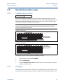
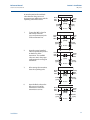
2.9.1
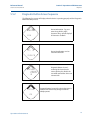
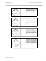
Configure process alerts
Fast Keys
2, 1, 6
Process alerts allow the transmitter to indicate when the configured data point is exceeded.
Process alerts can be set for pressure, temperature, or both. An alert will be displayed on a Field
Communicator, AMS Device Manager status screen or in the error section of the LCD Display.
The alert will reset once the value returns within range.
Note
HI alert value must be higher than the LO alert value. Both alert values must be within the
pressure or temperature sensor limits.
Units of Measurement
Example 1: Rising Alert
Alert “OFF”
Alert “ON”
Alert “OFF”
Alert Set Point
Deadband
Assigned Value
Time
Units of Measurement
Example 2: Falling Alert
Alert “OFF”
Alert “ON”
Alert “OFF”
Assigned Value
Alert Set Point
Deadband
Time
To configure the process alerts, perform the following procedure:
2.9.2
1.
From the Home screen, select 2: Configure.
2.
Select 1: Guided Setup.
3.
Select 6: Configure Process Alerts and follow the on-screen instructions to complete
configure of process alarms.
Damping
The Damping command introduces a delay in processing which increases the response time of
the transmitter; smoothing variations in output readings caused by rapid input changes. In the
Configuration
23
Reference Manual
Section 2: Configuration
00809-0100-4102, Rev AA
May 2013
2051 Wireless pressure transmitter, damping only takes effect when the device is placed in high
power refresh mode and during calibration. In normal power mode, the effective damping is 0.
Note that when the device is in high power refresh mode, battery power will be depleted rapidly.
Determine the appropriate damp setting based on the necessary response time, signal stability,
and other requirements of the loop dynamics of your system. The damping value of your device
is user selectable from 0 to 60 seconds.
Damping with a Field Communicator
From the HOME screen, enter the fast key sequence
Device Dashboard Fast Keys
2, 2, 2, 4
Enter desired Damping Value and select APPLY.
Damping with AMS Device Manager
Right click on the device and select Configure.
2.9.3
1.
Select Manual Setup.
2.
Within the Pressure Setup box, enter desired damping value and click Send.
3.
Carefully read the warning and click Yes if it is safe to apply the changes.
Write protect
The Rosemount 2051 Wireless pressure transmitter has a software write protect security
feature.
Enabling write protect with a Field Communicator
From the HOME screen, enter the fast key sequence
Device Dashboard Fast Keys
2, 2, 7, 1
Select Write Protect to enable.
Enabling write protect with AMS Device Manager
Right click on device and select Configure.
2.10
1.
Select Manual Setup.
2.
Select the tab labeled Device Information.
3.
Select Write Protect to enable this feature.
Diagnostics and service
Diagnostics and service functions listed below are primarily for use after field installation. The
Transmitter Test feature is designed to verify that the transmitter is operating properly, and can
be performed either on the bench or in the field.
24
Configuration
Reference Manual
Section 2: Configuration
00809-0100-4102, Rev AA
2.10.1
May 2013
Device reset
The master reset function will reset the device electronics. To perform a device reset:
Performing master reset using a Field Communicator
From the HOME screen, enter the fast key sequence
Device Dashboard Fast Keys
3, 5, 5
Performing master reset using AMS Device Manager
2.10.2
1.
From the Home screen, select 3: Service Tools.
2.
Select 5: Maintenance
3.
Select 5: Device Reset
Join status
Viewing join status using a Field Communicator
From the HOME screen, enter the fast key sequence
Device Dashboard Fast Keys
3, 4, 1
Viewing join status using AMS Device Manager
To view the join status of the device, perform the following procedure:
1.
From the Home screen, select 3: Service Tools.
2.
Select 4: Communications.
3.
Select 1: Join Status.
Wireless devices join the secure network through a four step process:
Configuration
Step 1. Network Found
Step 2. Network Security Clearance Granted
Step 3. Network Bandwidth Allocated
Step 4. Network Join Complete
25
Reference Manual
Section 2: Configuration
00809-0100-4102, Rev AA
May 2013
2.10.3
Number of available neighbors
Viewing number of available neighbors using a Field
Communicator
From the HOME screen, enter the fast key sequence
Device Dashboard Fast Keys
3, 4, 3
Viewing number of available neighbors using AMS Device
Manager
In a self-organizing network, the more neighbors a device has, the more robust the network will
be. To view the number of available neighbors for the wireless device, perform the following
procedure:
26
1.
From the Home screen, select 3: Service Tools.
2.
Select 4: Routine Maintenance.
3.
Select 3: Number of Available Neighbors.
Configuration
Reference Manual
Section 2: Configuration
00809-0100-4102, Rev AA
May 2013
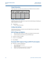
2.11
Advanced Functions for HART Protocol
2.11.1
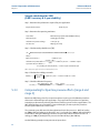
Saving, Recalling, and Cloning Configuration Data
Fast Keys
left arrow, 1, 2
Use the cloning feature of the Field Communicator or the AMS “User Configuration” feature to
configure several 2051 Wireless transmitters similarly. Cloning involves configuring a
transmitter, saving the configuration data, then sending a copy of the data to a separate
transmitter. Several possible procedures exist when saving, recalling, and cloning configuration
data. For complete instructions refer to the Field Communicator manual (publication no.
00809-0100-4276) or AMS Books Online. One common method is as follows:
Field Communicator
1.
Completely configure the first transmitter.
2.
Save the configuration data:
a.
Select F2 SAVE from the Field Communicator HOME/ONLINE screen.
b. Ensure that the location to which the data will be saved is set to MODULE. If it is not,
select 1: Location to set the save location to MODULE.
c.
Select 2: Name, to name the configuration data. The default is the transmitter tag
number.
d. Ensure that the data type is set to STANDARD. If the data type is NOT STANDARD,
select 3: Data Type to set the data type to STANDARD.
e.
Configuration
Select F2 SAVE.
3.
Connect and power the receiving transmitter and Field Communicator.
4.
Select the back arrow from the HOME/ONLINE screen. The Field Communicator menu
appears.
5.
Select 1: Offline, 2: Saved Configuration, 1: Module Contents to reach the MODULE
CONTENTS menu.
6.
Use the DOWN ARROW to scroll through the list of configurations in the memory
module, and use the RIGHT ARROW to select and retrieve the required configuration.
7.
Select 1: Edit.
8.
Select 1: Mark All.
9.
Select F2 SAVE.
10.
Use the DOWN ARROW to scroll through the list of configurations in the memory
module, and use the RIGHT ARROW to select the configuration again.
11.
Select 3: Send to download the configuration to the transmitter.
12.
Select OK after the control loop is set to manual.
13.
After the configuration has been sent, select OK.
27
Reference Manual
Section 2: Configuration
00809-0100-4102, Rev AA
May 2013
When finished, the Field Communicator informs you of the status. Repeat Steps 3 through 13 to
configure another transmitter.
Note
The transmitter receiving cloned data must have the same software version (or later) as the
original transmitter.
AMS creating a Reusable Copy
To create a reusable copy of a configuration perform the following procedure:
1.
Completely configure the first transmitter.
2.
Select View then User Configuration View from the menu bar (or click the toolbar
button).
3.
In the User Configuration window, right click and select New from the context menu.
4.
In the New window, select a device from the list of templates shown, and click OK.
5.
The template is copied into the User Configurations window, with the tag name
highlighted; rename it as appropriate and press Enter.
Note
A device icon can also be copied by dragging and dropping a device template or any other
device icon from AMS Explorer or Device Connection View into the User Configurations window.
The “Compare Configurations” window appears, showing the Current values of the copied
device on one side and mostly blank fields on the other (User Configuration) side.
6.
Transfer values from the current configuration to the user configuration as appropriate
or enter values by typing them into the available fields.
7.
Click Apply to apply the values, or click OK to apply the values and close the window.
AMS Applying a User Configuration
Any amount of user configurations can be created for the application. They can also be saved,
and applied to connected devices or to devices in the Device List or Plant Database.
To apply a user configuration perform the following procedure:
28
1.
Select the desired user configuration in the User Configurations window.
2.
Drag the icon onto a like device in AMS Explorer or Device Connection View. The
Compare Configurations window opens, showing the parameters of the target device
on one side and the parameters of the user configuration on the other.
3.
Transfer parameters from the user configuration to the target device as desired, Click
OK to apply the configuration and close the window.
Configuration
Section 3: Installation
Reference Manual
May 2013
00809-0100-4102, Rev AA
Section 3
Installation
Overview . . . . . . . . . . . . . . . . . . . . . . . . . . . . . . . . . . . . . . . . . . . . . . . . . . . . . . . . . . . . . . . page 29
Safety messages . . . . . . . . . . . . . . . . . . . . . . . . . . . . . . . . . . . . . . . . . . . . . . . . . . . . . . . . . page 29
Considerations . . . . . . . . . . . . . . . . . . . . . . . . . . . . . . . . . . . . . . . . . . . . . . . . . . . . . . . . . . page 31
Installation procedures . . . . . . . . . . . . . . . . . . . . . . . . . . . . . . . . . . . . . . . . . . . . . . . . . . . page 35
Installing the LCD display . . . . . . . . . . . . . . . . . . . . . . . . . . . . . . . . . . . . . . . . . . . . . . . . . page 46
Rosemount 304, 305 and 306 integral manifolds . . . . . . . . . . . . . . . . . . . . . . . . . . . . page 47
3.1
Overview
The information in this section covers installation considerations. A Quick Installation Guide
(document number 00825-0100-4102) is shipped with every transmitter to describe basic
installation and startup procedures. Dimensional drawings for each Rosemount 2051 Wireless
variation and mounting configuration are included in Appendix A: Specifications and Reference
Data.
Note
For transmitter disassembly refer to 6.3: Removing from service on page 88.
3.2
Safety messages
Procedures and instructions in this section may require special precautions to ensure the safety
of the personnel performing the operation. Information that raises potential safety issues is
indicated with a warning symbol (
). Refer to the following safety messages before
performing an operation preceded by this symbol.
Installation
29
Reference Manual
Section 3: Installation
00809-0100-4102, Rev AA
May 2013
3.2.1
Warnings ( )
Failure to follow these installation guidelines could result in death or
serious injury.
Make sure only qualified personnel perform the installation.
Explosions could result in death or serious injury:
Installation of this transmitter in an explosive environment must be in accordance with the
appropriate local, national, and international standards, codes, and practices. Please review
the approvals section of the 2051 Wireless reference manual for any restrictions associated
with a safe installation.
Before connecting a Field Communicator in an explosive atmosphere, make sure the
instruments are installed in accordance with intrinsically safe or non-incendive field
wiring practices.
Verify that the operating atmosphere of the transmitter is consistent with the
appropriate hazardous locations certifications
Process leaks could result in death or serious injury.
Install and tighten process connectors before applying pressure.
Electrical shock could cause death or serious injury.
Avoid contact with the leads and terminals. High voltage that may be present on leads
can cause electrical shock.
This device complies with Part 15 of the FCC Rules. Operation is subject to the following
conditions: This device may not cause harmful interference. This device must accept any
interference received, including interference that may cause undesired operation.
30
This device must be installed to ensure a minimum antenna separation distance of 20
cm (8 in.) from all persons.
Installation
Reference Manual
Section 3: Installation
00809-0100-4102, Rev AA
May 2013
Electrical shock can result in death or serious injury.
Avoid contact with the leads and terminals.
Process leaks could result in death or serious injury.
Install and tighten all four flange bolts before applying pressure.
Do not attempt to loosen or remove flange bolts while the transmitter is in service.
Replacement equipment or spare parts not approved by Emerson Process Management for
use as spare parts could reduce the pressure retaining capabilities of the transmitter and
may render the instrument dangerous.
Use only bolts supplied or sold by Emerson Process Management as spare parts.
Improper assembly of manifolds to traditional flange can damage sensor module.
For safe assembly of manifold to traditional flange, bolts must break back plane of
flange web (i.e., bolt hole) but must not contact sensor module housing.
The Power Module with the wireless unit contains a primary lithium-thionyl chloride
battery. Each Power Module contains approximately 5.0 grams of lithium. Under normal
conditions, the Power Module materials are self-contained and are not reactive as long as
the batteries and the pack integrity are maintained. Care should be taken to prevent
thermal, electrical or mechanical damage. Contacts should be protected to prevent
premature discharge.
3.3
Considerations
3.3.1
Installation considerations
Measurement performance depends upon proper installation of the transmitter and impulse
piping. Mount the transmitter close to the process and use a minimum of piping to achieve best
performance. Also, consider the need for easy access, personnel safety, practical field
calibration, and a suitable transmitter environment. Install the transmitter to minimize
vibration, shock, and temperature fluctuation.
3.3.2
Wireless considerations
Power up sequence
The Power Module should not be installed on any wireless device until the Smart Wireless
Gateway is installed and functioning properly. This transmitter uses the Green Power Module
(order model number 701PGNKF). Wireless devices should also be powered up in order of
proximity from the Smart Wireless Gateway, beginning with the closest. This will result in a
simpler and faster network installation. Enable Active Advertising on the Gateway to ensure that
new devices join the network faster. For more information, see the Smart Wireless Gateway
Manual (Doc. No. 00809-0200-4420).
Installation
31
Section 3: Installation
Reference Manual
00809-0100-4102, Rev AA
May 2013
Internal antenna position
The internal antenna is designed for multiple mounting orientations. The transmitter should be
mounted according to measurement best practices for your pressure measurement application.
The antenna should be approximately 3 ft (1 m) from any large structure or building to allow
clear communication to other devices.
Field communicator connections
In order for the Field Communicator to interface with the Rosemount 2051 Wireless
Transmitter, the Power Module must be connected. Refer to Figure 3-1 for a diagram on how to
connect the Field Communicator.
Figure 3-1. Field Communicator Connections
3.3.3
Mechanical considerations
Steam service
For steam service or for applications with process temperatures greater than the limits of the
transmitter, do not blow down impulse piping through the transmitter. Flush lines with the
blocking valves closed and refill lines with water before resuming measurement. Refer to Figure
3-11 on page 43 for correct mounting orientation.
Side mounted
When the transmitter is mounted on its side, position the Coplanar flange to ensure proper
venting or draining. Mount the flange as shown in Figure 3-11 on page 43, keeping drain/vent
connections on the bottom for gas service and on the top for liquid service.
3.3.4
Environmental considerations
32
Best practice is to mount the transmitter in an environment that has minimal ambient
temperature change. The transmitter electronics temperature operating limits are –40 to 185 °F
(–40 to 85 °C). Refer to Appendix A: Specifications and Reference Data that lists the sensing
element operating limits. Mount the transmitter so that it is not susceptible to vibration and
mechanical shock and does not have external contact with corrosive materials.
Installation
Reference Manual
Section 3: Installation
00809-0100-4102, Rev AA
May 2013
Figure 3-2. Installation Flowchart
START HERE
Configuration
No
Field Install
Yes
Configure
(Section 2)
Set Units
Verify
Mount
Transmitter
(page 36)
Review
Transmitter
Configuration
(page 20)
Install Power
Module
(page 45)
Check Process
Connection
(page 43)
Set Range
Points
Apply Pressure
Confirm
Transmitter
Configuration
(page 20)
Set Network ID
and Join Key
Within
Specifications?
No
Refer to
Section 4
Operation and
Maintenance
3.3.5
Yes
Trim Transmitter
for Mounting
Effects
(page 67)
Done
Draft range considerations
Installation
For the Rosemount 2051CD0 draft range pressure transmitter, it is best to mount the
transmitter with the isolators parallel to the ground. See Figure 3-3 on page 34 for a draft range
installation example on a 304 manifold. Installing the transmitter in this way reduces oil head
effect.
Installation
33
Reference Manual
Section 3: Installation
00809-0100-4102, Rev AA
May 2013
Tilting of the transmitter may cause a zero shift in the transmitter output, but can be eliminated
by performing a trim procedure.
Figure 3-3. Draft range installation example
A
A. Isolators
Reducing process noise
Rosemount 2051CD0 draft transmitters are sensitive to small pressure changes. Increasing the
damping will decrease output noise, but will further reduce response time. In gage applications,
it is important to minimize pressure fluctuations to the low side isolator.
Output damping
The Damping command introduces a delay in processing which increases the response time of
the transmitter; smoothing variations in output readings caused by rapid input changes. In the
Rosemount 2051 Wireless pressure transmitter, damping only takes effect when the device is
placed in high power refresh mode and during calibration. In normal power mode, the effective
damping is 0. Note that when the device is in high power refresh mode, battery power will be
depleted rapidly. Determine the appropriate damp setting based on the necessary response
time, signal stability, and other requirements of the loop dynamics of your system. The damping
value of your device is user selectable from 0 to 60 seconds.
Reference side filtering
In gage applications it is important to minimize fluctuations in atmospheric pressure to which
the low side isolator is exposed.
One method of reducing fluctuations in atmospheric pressure is to attach a length of tubing to
the reference side of the transmitter to act as a pressure buffer.
34
Installation
Reference Manual
Section 3: Installation
00809-0100-4102, Rev AA
3.4
May 2013
Installation procedures
For dimensional drawing information refer to Appendix A: Specifications and Reference Data on
page 89.
Process flange orientation
Mount the process flanges with sufficient clearance for process connections. For safety reasons,
place the drain/vent valves so the process fluid is directed away from possible human contact
when the vents are used. In addition, consider the need for a testing or calibration input.
Note
Most transmitters are calibrated in the horizontal position. Mounting the transmitter in any
other position will shift the zero point to the equivalent amount of liquid head pressure caused
by the varied mounting position. To reset zero point, refer to “Sensor Trim” on page 68.
Consider housing rotation
The electronics housing can be rotated up to 180 degrees in either direction to improve field
access, or to better view the optional LCD Display. To rotate the housing, perform the following
procedure:
1.
5
- -in. hex wrench.
Loosen the housing rotation set screw using a -----
2.
Retighten the housing rotation set screw.
64
Figure 3-4. Housing rotation
A
A. Housing Rotation Set Screw (5/64-in.)
Power Module side of electronics housing
Mount the transmitter so the Power Module side is accessible. Clearance of 3.5-in. (89 mm) is
required for cover and Power Module removal.
Circuit side of electronics housing
Provide 1.75 in. (45 mm) of clearance for units without an LCD display. Three inches of clearance
is required for cover removal if a meter is installed.
Installation
35
Reference Manual
Section 3: Installation
00809-0100-4102, Rev AA
May 2013
Environmental seal for housing
Always ensure a proper seal by installing the electronics housing cover(s) so that polymer
contacts polymer (i.e. no o-ring visible). Use Rosemount O-rings.
3.4.1
Mount the transmitter
Mounting brackets
Rosemount 2051 transmitters may be panel-mounted or pipe-mounted via an optional
mounting bracket. Refer to Table 3-1 for the complete offering and see Figure 3-5 on page 37 for
dimensional and mounting configuration information.
Table 3-1. Mounting brackets
2051 brackets
Process connections
Option
code
B4
36
Mounting
Materials
Flat
Pipe
Panel panel
Coplanar In-line Traditional mount mount mount
X
X
X
B1
X
B2
X
B3
X
B7
X
B8
X
B9
X
BA
X
BC
X
X
CS
SST
bracket bracket
X
X
X
X
X
X
X
X
X
CS
bolts
X
SST
bolts
X
X
X
X
X
X
X
X
X
X
X
X
X
X
X
X
X
Installation
Reference Manual
Section 3: Installation
00809-0100-4102, Rev AA
May 2013
Figure 3-5. Mounting bracket option code B4
A.
D.
C.
B.
A. 5/16 x 11/2 Bolts for Panel Mounting (Not Supplied)
B. 3.4 (85)
C. 3/8-16 x 11/4 Bolts for Mounting to Transmitter
D. 2.8 (71)
Note: Dimensions are in inches (millimeters).
Flange bolts
The Rosemount 2051 can be shipped with a Coplanar flange or a Traditional flange installed
with four 1.75-inch flange bolts. Mounting bolts and bolting configurations for the Coplanar and
Traditional flanges can be found in Figure 3-6 on page 38. Stainless steel bolts supplied by
Emerson Process Management are coated with a lubricant to ease installation. Carbon steel
bolts do not require lubrication. No additional lubricant should be applied when installing either
type of bolt. Bolts supplied by Emerson Process Management are identified by their head
markings:
B7M
Carbon Steel (CS) Head Markings
Stainless Steel (SST) Head Markings
Installation
660
CL A
316
B8M
KM
Alloy K-500 Head Marking
F593_
* The last digit in the F593_ head marking may
be any letter between A and M.
37
Reference Manual
Section 3: Installation
00809-0100-4102, Rev AA
May 2013
Bolt installation
Only use bolts supplied with the Rosemount 2051 or sold by Emerson Process Management as
spare parts. When installing the transmitter to one of the optional mounting brackets, torque
the bolts to 125 in-lb. (0,9 N-m). Use the following bolt installation procedure:
1.
Finger-tighten the bolts.
2.
Torque the bolts to the initial torque value using a crossing pattern.
3.
Torque the bolts to the final torque value using the same crossing pattern.
Torque values for the flange and manifold adapter bolts are as follows:
Table 3-2. Bolt Installation Torque Values
Bolt Material
Initial Torque Value
Final Torque Value
CS-ASTM-A445 Standard
300 in.-lb (34 N-m)
650 in.-lb (73 N-m)
316 SST—Option L4
150 in.-lb (17 N-m)
300 in.-lb (34 N-m)
ASTM-A-193-B7M—Option L5
300 in.-lb (34 N-m)
650 in.-lb (73 N-m)
Alloy K-500—Option L6
300 in.-lb (34 N-m)
650 in.-lb (73 N-m)
ASTM-A-453-660—Option L7
150 in.-lb (17 N-m)
300 in.-lb (34 N-m)
ASTM-A-193-B8M—Option L8
150 in.-lb (17 N-m)
300 in.-lb (34 N-m)
Figure 3-6. Traditional flange bolt configurations
A
B
C
D
C
C
Note
Dimensions are in inches
E
F
E
F
A. Differential Transmitter
B. Gage/Absolute Transmitter
C. Drain/Vent
D. Vented fitting
E. 1.75 (44) × 4
F. 1.50 (38) × 4(1)
(1)
38
For Gage and Absolute Transmitters: 150 (38) x 2
Installation
Reference Manual
Section 3: Installation
00809-0100-4102, Rev AA
May 2013
Figure 3-7. Mounting bolts and bolt configurations for coplanar flange
A
B
Description
Qty
Size
in.
(mm)
Differential Pressure
Flange Bolts
4
1.75
(44)
Flange/Adapter Bolts
4
2.88
(73)
Flange Bolts
4
1.75
(44)
Flange/Adapter Bolts
2
2.88
(73)
Gage/Absolute Pressure (1)
C
D
(1) Rosemount 2051T transmitters are direct mount and do
not require bolts for process connection.
A. Transmitter with flange bolts
B.Transmitter with flange adapters and flange/adapter bolts
C. 1.75 (44) × 4
D. 2.88 (73) × 4
Note: Dimensions are in inches (millimeters).
Figure 3-8. Mounting bracket option codes B1, B7, and BA
A
C
B
D
E
A. 3.75 (95)
B. 1.63 (41)
C. 4.09 (104)
D. 2.73 (69)
E. 4.97 (126)
Installation
39
Reference Manual
Section 3: Installation
00809-0100-4102, Rev AA
May 2013
Figure 3-9. Panel mounting bracket option codes B2 and B8
A
B
C
B
C
A
D
E
D
A. 3.75 (95)
B. 1.63 (41)
C. 4.09 (104)
D. 2.81 (71)
E. 4.5 (114)
A. 1.40 (36)
B. Mounting Holes 0.375 Diameter (10)
C. 1.405 (35,7)
D. 1.405 (35,7)
Figure 3-10. Flat mounting bracket option codes B3 and BC
B
A
D
C
A. 1.625 (41)
B. 2.125 (54)
C. 2.81 (71)
D. 8.00 (203)
Note: Dimensions are in inches (millimeters).
40
Installation
Reference Manual
Section 3: Installation
00809-0100-4102, Rev AA
3.4.2
May 2013
Impulse piping
Best practices
The piping between the process and the transmitter must accurately transfer the pressure to
obtain accurate measurements. There are five possible sources of error: leaks, friction loss
(particularly if purging is used), trapped gas in a liquid line, liquid in a gas line, and density
variations between the legs.
The best location for the transmitter in relation to the process pipe depends on the process
itself. Use the following guidelines to determine transmitter location and placement of impulse
piping:
Installation
Keep impulse piping as short as possible.
For liquid service, slope the impulse piping at least 1 inch per foot (8 cm per m) upward
from the transmitter toward the process connection.
For gas service, slope the impulse piping at least 1 inch per foot (8 cm per m) downward
from the transmitter toward the process connection.
Avoid high points in liquid lines and low points in gas lines.
Make sure both impulse legs are the same temperature.
Use impulse piping large enough to avoid friction effects and blockage.
Vent all gas from liquid piping legs.
When using a sealing fluid, fill both piping legs to the same level.
When purging, make the purge connection close to the process taps and purge
through equal lengths of the same size pipe. Avoid purging through the transmitter.
Keep corrosive or hot (above 250 °F [121 °C]) process material out of direct contact
with the sensor module and flanges.
Prevent sediment deposits in the impulse piping.
Keep the liquid head balanced on both legs of the impulse piping.
Avoid conditions that might allow process fluid to freeze within the process flange.
41
Reference Manual
Section 3: Installation
00809-0100-4102, Rev AA
May 2013
Mounting Requirements
Refer to Figure 3-11 on page 43 for examples of the following mounting configurations:
Liquid Flow Measurement
Place taps to the side of the line to prevent sediment deposits on the process isolators.
Mount the transmitter beside or below the taps so gases vent into the process line.
Mount drain/vent valve upward to allow gases to vent.
Gas Flow Measurement
Place taps in the top or side of the line.
Mount the transmitter beside or above the taps so to drain liquid into the process line.
Steam Flow Measurement
Place taps to the side of the line.
Mount the transmitter below the taps to ensure that impulse piping will remain filled
with condensate.
Fill impulse lines with water to prevent steam from contacting the transmitter directly
and to ensure accurate measurement start-up.
Note
For steam or other elevated temperature services, it is important that temperatures at the
Coplanar process flanges must not exceed 250 °F (121 °C) for transmitters with silicone fill, or
185 °F (85 °C) for inert fill. For vacuum service, these temperature limits are reduced to 220 °F
(104 °C) for silicone fill and 160 °F (71 °C) for inert fill.
42
Installation
Reference Manual
Section 3: Installation
00809-0100-4102, Rev AA
May 2013
Figure 3-11. Installation examples
Liquid Service
Gas Service
Steam Service
A
A
A
A. Drain/vent valves
3.4.3
Process connections
Coplanar or traditional process connection
Install and tighten all four flange bolts before applying pressure to avoid leakage. When properly
installed, the flange bolts will protrude through the top of the sensor module housing. Do not
attempt to loosen or remove the flange bolts while the transmitter is in service.
Flange adapters
Rosemount 2051DP and GP process connections on the transmitter flanges are 1/4–18 NPT.
Flange adapters are available with standard 1/2–14 NPT Class 2 connections. The flange adapters
allow users to disconnect from the process by removing the flange adapter bolts. Use
plant-approved lubricant or sealant when making the process connections. Refer to
Dimensional Drawings on page 101 for the distance between pressure connections. This
distance may be varied ±1/4 in. (6.4 mm) by rotating one or both of the flange adapters.
To install adapters to a Coplanar flange, perform the following procedure:
Installation
43
Reference Manual
Section 3: Installation
00809-0100-4102, Rev AA
May 2013
1.
Remove the flange bolts.
2.
Leaving the flange in place, move the adapters into position with the O-ring installed.
3.
Clamp the adapters and the Coplanar flange to the transmitter module using the longer
of the bolts supplied.
4.
Tighten the bolts. Refer to “Flange bolts” on page 37 for torque specifications.
Failure to install proper flange adapter o-rings may cause process leaks, which can result in death or
serious injury. The two flange adapters are distinguished by unique o-ring grooves. Only use the
o-ring that is designed for its specific flange adapter, as shown below.
ROSEMOUNT 2051S / 2051 / 2051 / 3001 / 3095
Flange Adapter
O-ring
PTFE Based
Elastomer
Note
PTFE O-rings should be replaced if the flange adapter is removed.
Whenever you remove flanges or adapters, visually inspect the PTFE O-rings. Replace them if
there are any signs of damage, such as nicks or cuts. If you replace the O-rings, re-torque the
flange bolts after installation to compensate for cold flow. Refer to the process sensor body
reassembly procedure in Section 6: Troubleshooting on page 83.
3.4.4
Inline process connection
Inline gage transmitter orientation
Interfering or blocking the atmospheric reference port will cause the transmitter to output
erroneous pressure values.
The low side pressure port on the inline gage transmitter is located in the neck of the
transmitter, behind the housing. The vent path is 360 degrees around the transmitter between
the housing and sensor (See Figure 3-12).
Keep the vent path free of any obstruction, such as paint, dust, and lubrication by mounting the
transmitter so that the process can drain away.
44
Installation
Reference Manual
Section 3: Installation
00809-0100-4102, Rev AA
May 2013
Figure 3-12. Inline gage low side pressure port
A
A. Low side pressure port (atmospheric reference)
a
Do not apply torque directly to the sensor module. Rotation between the sensor module
and the process connection can damage the electronics. To avoid damage, apply torque
only to the hex-shaped process connection.
Sensor Module
Process Connection
3.4.5
Power Module installation
Figure 3-13. Power Module
A
A. Power Module (5/64-inch hex wrench required)
Installation
45
Reference Manual
Section 3: Installation
00809-0100-4102, Rev AA
May 2013
To make connections, perform the following procedure:
3.4.6
1.
Remove the housing cover on the Power Module compartment side. The Power Module
supplies all power to the transmitter.
2.
Connect Power Module 701PGNKF.
3.
Replace the Power Module cover and tighten to safety specification (polymer to
polymer).
Installing the LCD display
Transmitters ordered with the LCD display will be shipped with the display installed.
Note
Only use Rosemount Wireless LCD Part Number: 00753-9004-0002
Note
An LCD from a wired device will not function in a wireless device.
In addition to housing rotation, the optional LCD display can be rotated in 90-degree increments
by squeezing the two tabs, pulling out, rotating and snapping back into place.
If LCD pins are inadvertently removed from the interface board, carefully re-insert the pins
before snapping the LCD display back into place.
Use the following procedure and Figure 3-14 to install the LCD display:
1.
Remove the back cover and Power Module.
2.
Remove the transmitter cover opposite the field terminal side. Do not remove the
instrument covers in explosive environments when the circuit is live.
3.
Engage the four-pin connector into the LCD display and snap into place.
Note the following LCD temperature limits:
Operating:–40 to 175 °F (–40 to 80 °C)
Storage:–40 to 185 °F (–40 to 85 °C)
46
Installation
Reference Manual
00809-0100-4102, Rev AA
Section 3: Installation
May 2013
Figure 3-14. Optional LCD Display
3.5
Rosemount 304, 305 and 306 integral manifolds
The Rosemount 305 Integral Manifold mounts directly to the transmitter and is available in two
designs: Traditional and Coplanar. The traditional 305 Integral Manifold can be mounted to
most primary elements with mounting adapters in the market today. The Rosemount 306
Integral Manifold is used with Rosemount 2051T In-line transmitters to provide block-and-bleed
valve capabilities of up to 10000 psi (690 bar). The Rosemount 304 comes in two basic styles:
traditional (flange x flange and flange x pipe) and wafer. The 304 traditional manifold comes in
2, 3, and 5-valve configurations. The 304 wafer manifold comes in 3 and 5 valve configurations.
Installation
47
Reference Manual
Section 3: Installation
00809-0100-4102, Rev AA
May 2013
Figure 3-15. Integral Manifold Designs
A
C
B
D
A. 2051C and 304 Conventional
B. 2051C and 305 Integral Coplanar
C. 2051C and 305 Integral Traditional
D. 2051T and 306 In-Line
3.5.1
Rosemount 305 Integral Manifold installation procedure
To install a 305 Integral Manifold to a 2051 Wireless transmitter:
1.
Inspect the PTFE sensor module O-rings. If the O-rings are undamaged, reusing them is
recommended. If the O-rings are damaged (if they have nicks or cuts, for example),
replace them with new O-rings.
Important
If replacing the O-rings, take care not to scratch or deface the O-ring grooves or the surface of
the isolating diaphragm while you remove the damaged O-rings.
2.
48
Install the Integral Manifold on the sensor module. Use the four 2.25-in. manifold bolts
for alignment. Finger tighten the bolts, then tighten the bolts incrementally in a cross
pattern as seen in Figure 3-16 on page 49 to final torque value. See “Flange bolts” on
page 37 for complete bolt installation information and torque values. When fully
tightened, the bolts should extend through the top of the module housing.
Installation
Reference Manual
Section 3: Installation
00809-0100-4102, Rev AA
May 2013
Figure 3-16. Bolt tightening pattern
3.
If the PTFE sensor module O-rings have been replaced, the flange bolts should be
re-tightened after installation to compensate for cold flow of the O-rings.
4.
If applicable, install flange adapters on the process end of the manifold using the
1.75-in. flange bolts supplied with the transmitter.
Note
Always perform a zero trim on the transmitter/manifold assembly after installation to eliminate
mounting effects. See Section 5: Operation and maintenance, “Sensor Trim” on page 68.
3.5.2
Rosemount 306 Integral Manifold installation procedure
The 306 Manifold is for use only with a 2051T Wireless In-line transmitter.
Assemble the 306 Manifold to the 2051T Wireless In-line transmitter with a thread sealant.
Installation
1.
Place transmitter into holding fixture.
2.
Apply appropriate thread paste or tape to threaded instrument end of the manifold.
3.
Count total threads on the manifold before starting assembly.
4.
Start turning the manifold by hand into the process connection on the transmitter.
49
Reference Manual
Section 3: Installation
00809-0100-4102, Rev AA
May 2013
Note
If using thread tape, be sure the thread tape does not strip when the manifold assembly is
started.
3.5.3
5.
Wrench tighten manifold into process connection. (Note: Minimum toque value is 425
in-lbs)
6.
Count how many threads are still showing. (Note: Minimum engagement is 3
revolutions)
7.
Subtract the number of threads showing (after tightening) from the total threads to
calculate the revolutions engaged. Further tighten until a minimum of 3 rotations is
achieved.
8.
For block and bleed manifold, verify the bleed screw is installed and tightened. For
two-valve manifold, verify the vent plug is installed and tightened.
9.
Leak-check assembly to maximum pressure range of transmitter.
Rosemount 304 Conventional Manifold installation
procedure
To install a 304 Conventional Manifold to a 2051 Wireless transmitter:
3.5.4
1.
Align the Conventional Manifold with the transmitter flange. Use the four manifold
bolts for alignment.
2.
Finger tighten the bolts, then tighten the bolts incrementally in a cross pattern to final
torque value. See “Flange bolts” on page 37 for complete bolt installation information
and torque values. When fully tightened, the bolts should extend through the top of
the sensor module housing.
3.
If applicable, install flange adapters on the process end of the manifold using the
1.75-in. flange bolts supplied with the transmitter.
Manifold operation
Improper installation or operation of manifolds may result in process leaks, which may cause
death or serious injury.
Always perform a zero trim on the transmitter/manifold assembly after installation to eliminate
any shift due to mounting effects. See Section 5: Operation and maintenance, “Sensor Trim
Overview” on page 67.
Three and five-valve configurations shown:
50
Installation
Reference Manual
Section 3: Installation
00809-0100-4102, Rev AA
May 2013
In normal operation the two block
valves between the process and
instrument ports will be open and the
equalizing valve will be closed.
L
H
Drain/
Vent
Valve
Drain/
Vent
Valve
Equalize
(closed)
Isolate
(open)
Isolate
(open)
Process
1.
To zero the 2051, close the
block valve to the low
pressure (downstream) side
of the transmitter first.
L
H
Drain/
Vent
Valve
Drain/
Vent
Valve
Equalize
(closed)
Isolate
(open)
Isolate
(closed)
Process
2.
Open the center (equalize)
valve to equalize the pressure
on both sides of the
transmitter. The manifold
valves are now in the proper
configuration for zeroing the
transmitter.
L
H
Drain/
Vent
Valve
Drain/
Vent
Valve
Equalize
(open)
Isolate
(closed)
Isolate
(open)
Process
3.
After zeroing the transmitter,
close the equalizing valve.
L
H
Drain/
Vent
Valve
Drain/
Vent
Valve
Equalize
(closed)
Isolate
(closed)
Isolate
(open)
Process
4.
Open the block valve on the
low pressure side of the
transmitter to return the
transmitter to service.
L
H
Drain/
Vent
Valve
Equalize
(closed)
Isolate
(open)
Drain/
Vent
Valve
Isolate
(open)
Process
Installation
51
Reference Manual
Section 3: Installation
00809-0100-4102, Rev AA
May 2013
Five-valve Natural Gas configurations shown:
In normal operation, the two block
valves between the process and
instrument ports will be open, and the
equalizing valves will be closed.
L
H
Test
(Plugged)
Test
(Plugged)
Equalize
(closed)
Equalize
(closed)
Isolate
(open)
Isolate
(open)
Process
1.
To zero the 2051, first close
the block valve on the low
pressure (downstream) side
of the transmitter.
Drain
Vent
Process
L
H
Test
(Plugged)
Test
(Plugged)
Equalize
(closed)
Equalize
(closed)
Isolate
(open)
Isolate
(closed)
Process
Drain
Vent
Process
Note
Do not open the low side equalize valve before the high side equalize valve. Doing so will
overpressure the transmitter.
2.
Open the equalize valve on
the high pressure (upstream)
side of the transmitter.
L
H
Test
(Plugged)
Test
(Plugged)
Equalize
(open)
Equalize
(closed)
Isolate
(open)
Process
52
Isolate
(closed)
Drain Vent
(closed)
Process
Installation
Reference Manual
Section 3: Installation
00809-0100-4102, Rev AA
May 2013
3.
Open the equalize valve on
the low pressure
(downstream) side of the
transmitter. The manifold is
now in the proper
configuration for zeroing the
transmitter.
L
H
Test
(Plugged)
Test
(Plugged)
Equalize
(open)
Isolate
(open)
Isolate
(closed)
Process
4.
After zeroing the transmitter,
close the equalize valve on
the low pressure
(downstream) side of the
transmitter.
Equalize
(open)
Drain Vent
(closed)
Process
L
H
Test
(Plugged)
Test
(Plugged)
Equalize
(open)
Equalize
(closed)
Isolate
(open)
Isolate
(closed)
Process
5.
Close the equalize valve on
the high pressure (upstream)
side.
Drain Vent
(closed)
Process
L
H
Test
(Plugged)
Test
(Plugged)
Equalize
(closed)
Equalize
(closed)
Isolate
(open)
Isolate
(closed)
Process
6.
Finally, to return the
transmitter to service, open
the low side isolation valve.
Drain Vent
(closed)
Process
L
H
Test
(Plugged)
Test
(Plugged)
Equalize
(closed)
Equalize
(closed)
Isolate
(open)
Process
Installation
Isolate
(open)
Drain Vent
(closed)
Process
53
Section 3: Installation
May 2013
54
Reference Manual
00809-0100-4102, Rev AA
Installation
Section 4: Commissioning
Reference Manual
May 2013
00809-0100-4102, Rev AA
Section 4
Commissioning
Safety messages . . . . . . . . . . . . . . . . . . . . . . . . . . . . . . . . . . . . . . . . . . . . . . . . . . . . . . . . . page 55
Viewing network status . . . . . . . . . . . . . . . . . . . . . . . . . . . . . . . . . . . . . . . . . . . . . . . . . . page 57
Verifying operation . . . . . . . . . . . . . . . . . . . . . . . . . . . . . . . . . . . . . . . . . . . . . . . . . . . . . . page 57
4.1
Overview
The information in this section covers installation considerations for the Rosemount 2051
Wireless Pressure Transmitter. A Quick Installation Guide is shipped with every transmitter to
describe pipe-fitting, wiring procedures and basic configuration for initial installation.
Note
For transmitter disassembly refer to sections 6.3: Removing from service on page 88.
4.2
Safety messages
Instructions and procedures in this section may require special precautions to ensure the safety
of the personnel performing the operations. Information that potentially raises safety issues is
indicated by a warning symbol ( ). Please refer to the following safety messages before
performing an operation preceded by this symbol.
Commissioning
55
Section 4: Commissioning
4.2.1
Reference Manual
00809-0100-4102, Rev AA
May 2013
Warnings ( )
Failure to follow these installation guidelines could result in death or
serious injury.
Make sure only qualified personnel perform the installation.
Explosions could result in death or serious injury:
Installation of this transmitter in an explosive environment must be in accordance with the
appropriate local, national, and international standards, codes, and practices. Please review
the approvals section of the 2051 Wireless reference manual for any restrictions associated
with a safe installation.
Before connecting a Field Communicator in an explosive atmosphere, make sure the
instruments are installed in accordance with intrinsically safe or non-incendive field
wiring practices.
Verify that the operating atmosphere of the transmitter is consistent with the
appropriate hazardous locations certifications
Process leaks could result in death or serious injury.
Install and tighten process connectors before applying pressure.
Electrical shock could cause death or serious injury.
Avoid contact with the leads and terminals. High voltage that may be present on leads
can cause electrical shock.
This device complies with Part 15 of the FCC Rules. Operation is subject to the following
conditions: This device may not cause harmful interference. This device must accept any
interference received, including interference that may cause undesired operation.
56
This device must be installed to ensure a minimum antenna separation distance of 20
cm (8 in.) from all persons.
Commissioning
Reference Manual
00809-0100-4102, Rev AA
4.3
Section 4: Commissioning
May 2013
Viewing network status
If the Rosemount 2051 Wireless was configured with the Network ID and Join Key and sufficient
time for network polling has passed, the transmitter should be connected to the network. To
verify connectivity, open the Smart Wireless Gateway’s integral web interface and navigate to
the Explorer page.
This page will display the transmitter’s HART tag, PV, SV, TV, QV, and Update Rate. A green
status indicator means that the device is working properly. A red indicator means that there is a
problem with either the device or its communication path. For more detail on a specific device,
click on the tag name.
4.4
Verifying operation
Operation can be verified in four locations, at the device via the Local Display, using the Field
Communicator, at the Smart Wireless Gateway’s integrated web interface, or by using AMS
Suite Wireless Configurator or AMS Device Manager.
Local Display
The LCD will display the PV value at the same rate as the configured update rate. Press the
Diagnostic button to display the TAG, Device ID, Network ID, Network Join Status and Device
Status screens.
For Device Status screens, see “LCD Screen Messages” on page 73.
Commissioning
57
Reference Manual
Section 4: Commissioning
00809-0100-4102, Rev AA
May 2013
Figure 4-1. Diagnostic Screen Sequence
Tag
Device ID
Network ID
Abcde
id - 12
netwk
Network Join
Status
Device Status
fgh
345678
netwk
Suply
OK
volts
3. 6 0
13 0 5
ID
Figure 4-2. Network Join Status Screens
Searching for
Network
Joining Network
Connected with
Limited
Bandwidth
Connected
NETwK
netwk
netwk
netwk
SRCHNG
NEGOT
LIM-OP
OK
Field Communicator
For HART Wireless transmitter communication, a Rosemount 2051 Wireless DD is required. To
obtain the latest DD, visit the Emerson Process Management Easy Upgrade site at:
http://www2.emersonprocess.com/en-US/documentation/deviceinstallkits.
The communication status may be verified in the wireless device using the following Fast Key
sequence.
Function
Communications
Key Sequence
3, 4
Menu Items
Join Status, Join Mode, Number of
Available Neighbors, Number of
Advertisements Heard, Number of
Join Attempts
Smart Wireless Gateway
Using the Gateway’s web interface, navigate to the Explorer page as shown in Figure 4-3 on
page 59. Locate the device in question and verify all status indicators are good (green).
58
Commissioning
Reference Manual
00809-0100-4102, Rev AA
Section 4: Commissioning
May 2013
Figure 4-3. Smart Wireless Gateway Explorer page.
AMS Suite Wireless Configurator
When the device has joined the network, it will appear in the Device Manager as illustrated in
Figure 4-4. For HART Wireless transmitter communication, a Rosemount 2051 Wireless DD is
required. To obtain the latest DD, visit the Emerson Process Management Easy Upgrade site at:
http://www2.emersonprocess.com/en-US/documentation/deviceinstallkits.
Figure 4-4. Device Manager
Troubleshooting
If the device is not joined to the network after power up, verify the correct configuration of the
Network ID and Join Key, and that Active Advertising has been enabled on the Gateway. The
Network ID and Join Key in the device must match the Network ID and Join Key of the Gateway.
The Network ID and Join Key may be obtained from the Gateway on the Setup>Network>Settings page of the web server (see Figure 4-5 on page 60). The Network ID and Join Key may be
changed in the wireless device by following the Fast Key sequence shown below.
Commissioning
59
Reference Manual
Section 4: Commissioning
00809-0100-4102, Rev AA
May 2013
Function
Key Sequence
Menu Items
Join Device to
Network
2, 1, 3
Network ID, Set Join Key
Figure 4-5. Smart Wireless Gateway Network Settings
4.4.1
Using the Field Communicator
Note
In order to communicate with a Field Communicator, power the Rosemount 2051 Wireless
Transmitter by connecting the Power Module. For more information on the Power Module, refer
to the Power Module product data sheet (Document No 00813-0100-4701).
Table 4-1 includes Fast Key sequences frequently used to interrogate and configure the device.
60
Commissioning
Reference Manual
Section 4: Commissioning
00809-0100-4102, Rev AA
May 2013
Table 4-1. Rosemount 2051 Wireless Fast Key Sequence
Function
Key
Sequence
Device Information
2, 2, 9
Identification, Model Numbers, Flange
Information, Remote Seal Information,
Serial Number
Guided Setup
2, 1
Basic Setup, Join Device to Network,
Configure Update Rates, Alert Setup
Manual Setup
2, 2
Wireless, Sensor, HART, Security, Device
Information, Power
Wireless
2, 2, 1
Network ID, Join Device to Network,
Broadcast Information
Menu Items
Figure 4-6. Field Communicator Connections
4.5
Configuring transmitter security
There are two security methods with the Rosemount 2051 Wireless transmitter.
HART Lock
Configuration Buttons lock
HART lock
The HART Lock prevents changes to the transmitter configuration from all sources; all changes
requested via HART and local configuration buttons will be rejected. The HART Lock can only be
set via HART communication. The HART Lock can be enabled or disabled with a Field
Communicator or AMS Device Manager.
Commissioning
61
Reference Manual
Section 4: Commissioning
00809-0100-4102, Rev AA
May 2013
Configuring HART Lock using Field Communicator
From the HOME screen, enter the fast key sequence
Device Dashboard Fast Keys
2, 2, 7, 2
Configuring HART Lock using AMS Device Manager
1.
Right click on the device and select Configure.
2.
Under Manual Setup select the Security tab.
3.
Click Lock/Unlock button under HART Lock (Software) and follow the screen prompts.
Configuration Button lock
The configuration button lock disables all local button functionality. Changes to the transmitter
configuration from the local buttons will be rejected. Local external keys can be locked via HART
communication only.
Configuring configuration button lock using a Field
Communicator
From the HOME screen, enter the fast key sequence
Device Dashboard Fast Keys
2, 2, 7, 4
Configuring configuration button lock using AMS device
Manager
62
1.
Right click on the device and select Configure.
2.
Under Manual Setup select the Security tab.
3.
Within the Configuration Buttons dropdown menu select Disabled to lock external
local keys.
4.
Click Send.
5.
Confirm service reason and click Yes.
Commissioning
Reference Manual
Section 5: Operation and Maintenance
00809-0100-4102, Rev AA
May 2013
Section 5
Operation and maintenance
Overview . . . . . . . . . . . . . . . . . . . . . . . . . . . . . . . . . . . . . . . . . . . . . . . . . . . . . . . . . . . . . . . page 63
Calibration overview . . . . . . . . . . . . . . . . . . . . . . . . . . . . . . . . . . . . . . . . . . . . . . . . . . . . . page 63
LCD Screen Messages . . . . . . . . . . . . . . . . . . . . . . . . . . . . . . . . . . . . . . . . . . . . . . . . . . . . . page 73
5.1
Overview
This section contains information on commissioning and operating 2051 Wireless Pressure
Transmitters.
Field Communicator and AMS instructions are given to perform configuration functions. For
convenience, Field Communicator fast key sequences are labeled “Fast Keys” for each software
function below the appropriate headings.
5.2
Safety messages
Instructions and procedures in this section may require special precautions to ensure the safety
of the personnel performing the operations. Information that potentially raises safety issues is
indicated by a warning symbol ( ). Please refer to the following safety messages before
performing an operation preceded by this symbol.
5.3
Calibration overview
Calibrating a 2051 Wireless transmitter may include the following procedures:
Sensor Trim: Adjusts the position of the factory sensor characterization curve to
optimize performance over a specified pressure range, or to adjust for mounting
effects.
The Rosemount 2051 sensor module contains information about the sensor’s specific characteristics in response to pressure and temperature inputs. A smart transmitter compensates for
these sensor variations. The process of generating the sensor performance profile is called
factory sensor characterization.
Sensor trimming requires an accurate pressure input and adds additional compensation that
adjusts the position of the factory sensor characterization curve to optimize performance over a
specific pressure range.
Note
Sensor trimming adjusts the position of the factory sensor characterization curve. It is possible
to degrade performance of the transmitter if the trim is done improperly or with inaccurate
equipment.
Operation and maintenance
63
Reference Manual
Section 5: Operation and Maintenance
00809-0100-4102, Rev AA
May 2013
Absolute pressure transmitters (2051CA and 2051TA) are calibrated at the factory.
Trimming adjusts the position of the factory characterization curve. It is possible to
degrade performance of the transmitter if any trim is done improperly or with inaccurate
equipment.
Table 5-1. Recommended Calibration Tasks
Transmitter
2051CD
2051CG
2051L
2051TG, Range
1-4
Bench Calibration Tasks
1.
Set output configuration parameters:
a.
Set the range points.
b.
Set the output units.
c.
Set the output type.
2.
2051CA
2051TA
2051TG, Range 5
Optional: Perform a sensor trim.
(Accurate pressure source required.)
Set output configuration parameters:
1.
2.
a.
Set the range points.
b.
Set the output units.
c.
Set the output type.
Field Calibration Tasks
1.
Reconfigure parameters if
necessary.
2.
Zero trim the transmitter to
compensate for mounting effects
or static pressure effects.
1.
Reconfigure parameters if
necessary.
2.
Perform low trim value section of
the sensor trim procedure to
correct for mounting position
effects.
Optional: Perform a sensor trim if
equipment available (accurate
absolute pressure source required),
otherwise perform the low trim value
section of the sensor trim procedure.
Note:
For 2051CA, 2051TA range 0 and range 5 devices, an accurate absolute pressure source is
required.
5.3.1
Determining necessary Sensor Trims
Bench calibrations allow for calibrating the instrument for its desired range of operation.
Straight forward connections to pressure source allow for a full calibration at the planned
operating points. Exercising the Transmitter over the desired pressure range allows for
verification of the output value. “Sensor Trim” on page 68 discusses how the trim operations
change the calibration. It is possible to degrade the performance of the transmitter if a trim is
done improperly or with inaccurate equipment. The transmitter can be set back to factory
settings using the Recall Factory Trim command in “Recall Factory Trim—Sensor Trim” on
page 70.
64
Operation and maintenance
Reference Manual
Section 5: Operation and Maintenance
00809-0100-4102, Rev AA
May 2013
For transmitters that are field installed, the manifolds discussed in “Rosemount 304, 305 and
306 integral manifolds” on page 47 allow the differential transmitter to be zeroed using the zero
trim function. Both 3-valve and 5-valve manifolds are discussed. This field calibration will
eliminate any pressure offsets caused by mounting effects (head effect of the oil fill) and static
pressure effects of the process.
Determine the necessary trims with the following steps.
1.
Apply Pressure
2.
Check digital pressure, if the digital pressure does not match the applied pressure,
perform a digital zero trim. See “Sensor Trim” on page 68.
Trimming with configuration buttons
Local configuration buttons are buttons located inside the housing of the transmitter. To access
the buttons, remove the housing cover.
Digital Zero Trim (DZ): Used for performing a sensor zero trim. See “Recommended
Calibration Tasks” on page 64 for trim instructions.
Figure 5-1 shows the location of the digital zero button.
D
ero
lZ
ita m
ig Tri
Figure 5-1. Digital zero button location
A
A. Digital zero button
5.3.2
Determining calibration frequency
Calibration frequency can vary greatly depending on the application, performance
requirements, and process conditions. Use the following procedure to determine calibration
frequency that meets the needs of your application.
1.
Determine the performance required for your application.
2.
Determine the operating conditions.
3.
Calculate the Total Probable Error (TPE).
4.
Calculate the stability per month.
5.
Calculate the calibration frequency.
Operation and maintenance
65
Reference Manual
Section 5: Operation and Maintenance
00809-0100-4102, Rev AA
May 2013
Sample calculation for 2051
(0.04% accuracy & 5-year stability)
Step 1: Determine the performance required for your application.
Required Performance:
0.20% of span
Step 2: Determine the operating conditions.
Transmitter:
2051CD, Range 2 [URL=250 inH2O(623 mbar)]
Calibrated Span:
150 inH2O (374 mbar)
Ambient Temperature Change:
± 50 °F (28 °C)
Line Pressure:
500 psig (34,5 bar)
Step 3: Calculate total probable error (TPE).
TPE =
2
2
2
ReferenceAccuracy + TemperatureEffect + StaticPressureEffect = 0.105% of span
Where:
Reference Accuracy =
± 0.04% of span
0.0125 URL
Ambient Temperature Effect = ----------------------------------------- + 0.0625 % per 50 °F = 0.0833% of span
Span
Span Static Pressure Effect(1) =
0.1% reading per 1000 psi (69 bar) = 0.05% of span at maximum span
(1)Zero static pressure effect removed by zero trimming at line pressure.
Step 4: Calculate the stability per month.
0.125 URL
Stability = --------------------------------------- % of span for 5 years = 0.0021% of URL for 1 month
Span
Step 5: Calculate calibration frequency.
Req. Performance – TPE
0.2% – 0.105%
Cal. Freq. = ----------------------------------------------------------------------- = --------------------------------------------- = 45xmonths
Stability per Month
0.0021%
5.3.3
Compensating for Span line pressure effects (range 4 and
range 5)
Rosemount 2051 Range 4 and 5 pressure transmitters require a special calibration procedure
when used in differential pressure applications. The purpose of this procedure is to optimize
transmitter performance by reducing the effect of static line pressure in these applications. The
2051 differential pressure transmitters (ranges 0 through 3) do not require this procedure
because optimization occurs at the sensor.
The systematic span shift caused by the application of static line pressure is -0.95% of reading
per 1000psi (69 bar) for Range 4 transmitters, and -1% of reading per 1000psi (69 bar) for Range
5 transmitters. Using the following procedure, the span effect can be corrected to ±0.2% of
reading per 1000 psi (69 bar) for line pressures from 0 to 3626 psi (0 to 250 bar).
Use the following example to compute correct input values.
66
Operation and maintenance
Reference Manual
Section 5: Operation and Maintenance
00809-0100-4102, Rev AA
May 2013
Example
A range 4 differential pressure HART transmitter (2051CD4...) will be used in an application with
a static line pressure of 1200 psi (83 bar). The transmitter output is ranged with the Lower
Range Value at 500 inH20 (1, 2 bar) and the Upper Range Value at 1500 inH20 (3, 7 bar). To
correct for systematic error caused by high static line pressure, first use the following formulas
to determine the corrected values for the high trim value.
High Trim Value:
HT = (URV - (S/100 x P/1000 x LRV))
Where:
HT =
Corrected High Trim Value
URV =
Upper Range Value
S=
Span shift per specification (as a percent of reading)
P=
Static Line Pressure in psi
URV =
1500 inH2O (3.74 bar)
S=
-0.95%
P=
1200 psi
LT =
1500 - (-0.95%/100 x 1200 psi/1000 psi x 1500 inH2O)
LT =
1517.1 inH20
In this example:
Complete the Upper Sensor Trim procedure as described in “Sensor Trim” on page 68. In the
example above, at step 4, apply the nominal pressure value of 1500 inH20. However, enter the
calculated correct upper Sensor Trim value of 1517.1 inH20 with a Field Communicator.
Note
The Range Values for the upper and lower range points should be at the nominal URV and LRV. In
the example above, the values are 1500 inH20 and 500 inH20 respectively. Confirm the values
on the HOME screen of the Field Communicator. Modify, if needed, by following the steps in
“Set range points” on page 19.
5.4
Trim the pressure signal
5.4.1
Sensor Trim Overview
A Sensor Trim corrects the pressure offset and pressure range to match a pressure standard. The
Upper Sensor Trim corrects the pressure range and the Lower Sensor Trim (Zero Trim) corrects
the pressure offset. An accurate pressure standard is required for full calibration. A zero trim can
be performed if the process is vented, or the high and low side pressure are equal (for
differential pressure transmitters).
Zero trim is a single-point offset adjustment. It is useful for compensating for mounting position
effects and is most effective when performed with the transmitter installed in its final mounting
Operation and maintenance
67
Reference Manual
Section 5: Operation and Maintenance
00809-0100-4102, Rev AA
May 2013
position. Since this correction maintains the slope of the characterization curve, it should not be
used in place of a sensor trim over the full sensor range.
When performing a zero trim, ensure that the equalizing valve is open and all wet legs are filled
to the correct levels. Line pressure should be applied to the transmitter during a zero trim to
eliminate line pressure errors. Refer to “Manifold operation” on page 50.
Note
Do not perform a zero trim on 2051 Wireless absolute pressure transmitters. Zero trim is zero
based, and absolute pressure transmitters reference absolute zero. To correct mounting
position effects on a 2051 Wireless absolute pressure transmitter, perform a low trim within the
sensor trim function. The low trim function provides an offset correction similar to the zero trim
function, but it does not require zero-based input.
Sensor trim is a two-point sensor calibration where two end-point pressures are applied, and all
output is linearized between them. Always adjust the low trim value first to establish the correct
offset. Adjustment of the high trim value provides a slope correction to the characterization
curve based on the low trim value. The trim values allow you to optimize performance over your
specified measuring range at the calibration temperature.
During a trim operation, the 2051 Wireless is placed in high power refresh mode, which
provides frequent pressure measurement updates and allows the configured damping to take
effect. This behavior allows for more accurate calibration of the device. When the device is in
high power refresh mode, the battery power supply will be depleted more rapidly.
Figure 5-2. Sensor Trim example
A.
A.
B.
B.
A. Before Trim
B. After Trim
5.4.2
Sensor Trim
When performing a Sensor Trim, both the upper and lower limits can be trimmed. If both upper
and lower trims are to be performed, the lower trim must be done prior to the upper trim.
68
Operation and maintenance
Reference Manual
Section 5: Operation and Maintenance
00809-0100-4102, Rev AA
May 2013
Note
Use a pressure input source that is at least four times more accurate than the transmitter, and
allow the input pressure to stabilize for ten seconds before entering any values.
Performing a Sensor Trim with a Field Communicator
From the Home screen, enter the fast key sequence and follow the steps within the Field
Communicator to complete the Sensor Trim.
Fast Keys
3, 5, 1
To calibrate the transmitter using the sensor trim function:
1.
Assemble and power the entire calibration system including the 2051, Field
Communicator/AMS, power supply, pressure input source, and readout device.
2.
From the Home screen, select 3: Service Tools.
3.
Select 5: Maintenance
4.
Select 1: Pressure Calibration.
Note
Select pressure points so that lower and upper values are equal to or outside the expected
process operation range.
5.
Follow the on-screen instructions to complete the adjustment of the lower value.
6.
Repeat the procedure for the upper value. Select 1: Upper Sensor Trim and follow the
on-screen instructions to complete the adjustment of the upper value.
Performing a Sensor Trim with AMS Device Manager
Right click on the device and, under the Method drop down menu, move cursor over Calibrate
and, under Sensor Trim, select Lower Sensor Trim.
1.
Follow the screen prompts to perform a Sensor Trim using AMS Device Manager.
2.
If desired right click on the device and under the Method drop down menu, move cursor
over Calibrate and under Sensor Trim and select Upper Sensor Trim
Performing a Digital Zero Trim (option DZ)
A Digital Zero Trim (option DZ) provides the same function as a zero/lower Sensor Trim, but can
be completed in hazardous areas at any given time by simply pushing the Zero Trim button
when the transmitter is at zero pressure. If the transmitter is not close enough to zero when the
button is pushed, the command may fail due to excess correction. If ordered, a Digital Zero Trim
can be performed by utilizing configuration buttons located inside the housing of the
transmitter, see Figure 5-1 on page 65 for DZ button location.
1.
2.
Remove the electronics housing cover.
Press and hold the Digital zero button for at least two seconds then release to perform a
Digital Zero Trim
69
Operation and maintenance
Reference Manual
Section 5: Operation and Maintenance
00809-0100-4102, Rev AA
May 2013
5.4.3
Recall Factory Trim—Sensor Trim
The Recall Factory Trim—Sensor Trim command allows the restoration of the as-shipped factory
settings of the Sensor Trim. This command can be useful for recovering from an inadvertent zero
trim of an absolute pressure unit or inaccurate pressure source.
Recalling factory trim with AMS
Right click on the device and, under the Method drop down menu, move cursor over Calibrate
and select Restore Factory Calibration.
5.4.4
1.
Click Next after setting the control loop to manual.
2.
Select Sensor Trim under Trim to recall and click Next.
3.
Follow the screen prompts to recall Sensor Trim.
Line Pressure Effect (Range 2 and Range 3)
The following specifications show the static pressure effect for the Rosemount 2051 Range 2
and Range 3 pressure transmitters used in differential pressure applications where line pressure
exceeds 2000 psi (138 bar).
Zero Effect
± 0.1% of the upper range limit plus an additional ± 0.1% of upper range limit error for each 1000
psi (69 bar) of line pressure above 2000 psi (138 bar).
Example: Line pressure is 3000 psi (207 bar) for Ultra performance transmitter. Zero effect error
calculation:
± {0.05 + 0.1 x [3 kpsi - 2 kpsi]} = ± 0.15% of the upper range limit
Span Effect
Refer to “Line Pressure Effect” on page 91.
5.4.5
Compensating for Line Pressure (Range 4 and Range 5)
The Rosemount 2051 Wireless Range 4 and 5 pressure transmitters require a special calibration
procedure when used in differential pressure applications. The purpose of this procedure is to
optimize transmitter performance by reducing the effect of static line pressure in these
applications. The 2051 Wireless differential pressure transmitters (Ranges 1, 2, and 3) do not
require this procedure because optimization occurs in the sensor.
Applying high static pressure to the 2051 Wireless Range 4 and Range 5 pressure transmitters
causes a systematic shift in the output. This shift is linear with static pressure; correct it by
performing the “Sensor Trim” procedure on page 68.
The following specifications show the static pressure effect for the 2051 Wireless Range 4 and
Range 5 transmitters used in differential pressure applications:
70
Operation and maintenance
Reference Manual
Section 5: Operation and Maintenance
00809-0100-4102, Rev AA
May 2013
Zero Effect:
± 0.1% of the upper range limit per 1000 psi (69 bar) for line pressures from 0 to 2000 psi (0 to
138 bar)
For line pressures above 2000 psi (138 bar), the zero effect error is ± 0.2% of the upper range
limit plus an additional ± 0.2% of upper range limit error for each 1000 psi (69 bar) of line
pressure above 2000 psi (138 bar).
Example: Line pressure is 3000 psi (3 kpsi). Zero effect error calculation:
± {0.2 + 0.2 x [3 kpsi - 2 kpsi]} = ± 0.4% of the upper range limit
Span Effect:
Correctable to ±0.2% of reading per 1000 psi (69 bar) for line pressures from 0 to 3626 psi (0 to
250 bar)
The systematic span shift caused by the application of static line pressure is -1.00% of reading
per 1000 psi (69 bar) for Range 4 transmitters, and -1.25% of reading per 1000 psi (69 bar) for
Range 5 transmitters.
Use the following example to compute corrected input values.
Example
A transmitter with model number 2051_CD4 will be used in a differential pressure application
where the static line pressure is 1200 psi (83 bar). The transmitter output is ranged with 4 mA at
500 inH2O (1,2 bar) and 20 mA at 1500 inH2O (3,7 bar).
To correct for systematic error caused by high static line pressure, first use the following
formulas to determine corrected values for the low trim and high trim.
LT = LRV + S x (LRV) x P
Where:
LT =
Corrected Low Trim Value
LRV =
Lower Range Value
S=
–(Span shift per specification)
P=
Static Line Pressure
HT = URV + S x (URV) x P
Where:
HT =
Corrected High Trim Value
URV =
Upper Range Value
S=
–(Span shift per specification)
P=
Static Line Pressure
URV =
1500 inH2O (3.74 bar)
LRV =
500 inH2O (1.25 bar)
P=
1200 psi (82.74 bar)
S=
± 0.01/1000
In this example:
Operation and maintenance
71
Reference Manual
Section 5: Operation and Maintenance
00809-0100-4102, Rev AA
May 2013
To calculate the low trim (LT) value:
LT =
500 + (0.01/1000)(500)(1200)
LT =
506 inH2O (1.26 bar)
To calculate the high trim (HT) value:
HT =
1500 + (0.01/1000)(1500)(1200)
HT =
1518 inH2O (3.78 bar)
Complete a 2051 Wireless sensor trim and enter the corrected values for low trim (LT) and high
trim (HT), refer to “Sensor Trim” on page 68.
Enter the corrected input values for low trim and high trim through the Field Communicator
keypad after you apply the nominal value of pressure as the transmitter input.
Note
After sensor trimming 2051 Wireless Range 4 and 5 transmitters for high differential pressure
applications, verify that the Lower and Upper Operating points are at nominal values using the
Field Communicator.
72
Operation and maintenance
Reference Manual
Section 5: Operation and Maintenance
00809-0100-4102, Rev AA
May 2013
5.5
LCD Screen Messages
5.5.1
Startup Screen Sequence
The following screens will display when the Power Module is first connected to the Rosemount
2051 Wireless.
XXXXX
XXXXxxx
xxxxxx
2051
All Segments On: used to visually
determine if there are any bad
segments on the LCD
Device Identification: used to
determine Device Type.
WIrels
Abcde
fgh
PRESS
5 8. 0
Device Information - Tag: user
entered tag which is eight
characters long - will not display if
all characters are blank
PV Screen - process pressure
PSI
Operation and maintenance
73
Section 5: Operation and Maintenance
Reference Manual
00809-0100-4102, Rev AA
May 2013
SNSR
2 5. 0 0
SV Screen - sensor temperature
value
deg c
DEV
2 5. 2 5
TV Screen - device temperature
value
deg c
Suply
3. 6 0
QV Screen - voltage reading at the
power supply terminals
volts
PRCNT
7. 2 1
Percent Range Screen - percent
range reading
RANGE
alert
presnt
74
Alert Screen - at least one alert is
present - this screen will not
display if no alerts are present
Operation and maintenance
Reference Manual
Section 5: Operation and Maintenance
00809-0100-4102, Rev AA
5.5.2
May 2013
Diagnostic Button Screen Sequence
The following five screens will display when the device is operating properly and the Diagnostic
Button has been pressed.
Abcde
fgh
id - 12
Device Information - Tag: user
entered tag which is eight
characters long - will not display if
all characters are blank
Device Identification: used to
determine Device ID
345678
netwk
13 0 5
ID
netwk
Diagnostic Button Screen 3:
assuming the device has the
correct join key, this ID tells the
user what network the device can
connect with
Diagnostic Button Screen 4: the device has joined a
network and has been fully configured and has
multiple parents
OK
Operation and maintenance
75
Reference Manual
Section 5: Operation and Maintenance
00809-0100-4102, Rev AA
May 2013
Suply
3. 6 0
Diagnostic Button Screen 5:
voltage reading at the power
supply terminals
volts
5.5.3
Network Diagnostic Status Screens
These screens display the network status of the device. Only one will be shown during the
startup sequence or diagnostic sequence.
netwk
Diagnostic Button Screen 4.1: the device is
attempting to start the radio
unknwn
netwk
Diagnostic Button Screen 4.2: the device has just
restarted
INIT
netwk
Diagnostic Button Screen 4.3: the device is starting
to join the process
idle
76
Operation and maintenance
Reference Manual
Section 5: Operation and Maintenance
00809-0100-4102, Rev AA
May 2013
netwk
Diagnostic Button Screen 4.4: the device is in a
disconnected state and requires a “Force Join”
command to join the network
DISCNT
NETwK
Diagnostic Button Screen 4.5: the device is
searching for the Network
SRCHNG
netwk
Diagnostic Button Screen 4.6: the device is
attempting to join a network
NEGOT
netwk
Diagnostic Button Screen 4.7: the device is
connected to the Network, but is in a
“Quarantined” state
conect
netwk
Diagnostic Button Screen 4.8: the device is joined
and operational, but is running with limited
bandwidth for sending periodic data
LIM-OP
Operation and maintenance
77
Section 5: Operation and Maintenance
Reference Manual
00809-0100-4102, Rev AA
May 2013
netwk
Diagnostic Button Screen 4.9: the device has joined
a network and has been fully configured and has
multiple parents
OK
78
Operation and maintenance
Reference Manual
Section 5: Operation and Maintenance
00809-0100-4102, Rev AA
5.5.4
May 2013
Device Diagnostic Screens
The following screens will show the device diagnostics depending on the state of the device.
DEV
fAilur
PRESS
5 8. 0
Device Information - Status: there
is a critical error which may
prevent the device from
operating correctly. Check
additional status screens for more
information.
PV Screen - process pressure
value
PSI
SNSR
2 5. 0 0
SV Screen - sensor temperature
value
deg c
DEV
2 5. 2 5
TV Screen - device temperature
value
deg c
Operation and maintenance
79
Section 5: Operation and Maintenance
Reference Manual
00809-0100-4102, Rev AA
May 2013
Suply
3. 6 0
QV Screen - voltage reading at the
power supply terminals
volts
PRCNT
7. 2 1
Percent Range Screen - percent
range reading
RANGE
alert
presnt
Abcde
fgh
id - 12
345678
80
Alert Screen - at least one alert is
present - this screen will not
display if no alerts are present
Diagnostic Button Screen 1 - Tag:
user entered tag which is eight
characters long - will not display if
all characters are blank
Diagnostic Button Screen 2: the
device’s identifier that is used to
make up the HART long address the Smart Wireless Gateway may
use this to help identify devices if
no unique user tag is available
Operation and maintenance
Reference Manual
Section 5: Operation and Maintenance
00809-0100-4102, Rev AA
May 2013
suply
failur
suply
low
radio
failur
confg
failur
Operation and maintenance
Diagnostic Button Screen 7.1: the
terminal voltage has dropped
below level of operating limit.
Replace the Power Module
(Part Number: 701PGNKF)
Diagnostic Button Screen 7.2: the
terminal voltage is below the
recommended operating range the Power Module should be
replaced
Diagnostic Button Screen 8: the
device may not be able to
communicate with the radio or
the radio has an internal error. In
this state the device may still be
operational and publishing HART
data
Diagnostic Button Screen 9.1:
configuration of the transmitter is
invalid such that critical operation
of the device may be affected check the extended configuration
status to identify which
configuration item(s) need to be
corrected
81
Reference Manual
Section 5: Operation and Maintenance
00809-0100-4102, Rev AA
May 2013
confg
warn
snsr
failur
snsr
warn
Diagnostic Button Screen 9.2:
configuration of the transmitter is
invalid such that non-critical
operation of the device may be
affected - check the extended
configuration status to identify
which configuration item(s) need
to be corrected
Diagnostic Button Screen 10.1: a
sensor attached to the
transmitter has failed, and valid
readings from that sensor are no
longer possible - check the sensor
and sensor wiring connections check additional status for more
detailed information of the failure
source
Diagnostic Button Screen 10.2: a
sensor attached to the
transmitter is degraded, readings
from that sensor may not be
within accuracy specifications check the process, and sensor
wiring connections - check
additional status for more
detailed information of the
warning source
Note
Use the Rosemount Wireless LCD Part Number: 00753-9004-0002.
82
Operation and maintenance
Section 6: Troubleshooting
Reference Manual
May 2013
00809-0100-4102, Rev AA
Section 6
Troubleshooting
Overview . . . . . . . . . . . . . . . . . . . . . . . . . . . . . . . . . . . . . . . . . . . . . . . . . . . . . . . . . . . . . . . page 83
Safety messages . . . . . . . . . . . . . . . . . . . . . . . . . . . . . . . . . . . . . . . . . . . . . . . . . . . . . . . . . page 83
Removing from service . . . . . . . . . . . . . . . . . . . . . . . . . . . . . . . . . . . . . . . . . . . . . . . . . . . page 88
6.1
Overview
Table 6-1, Table 6-2, and Table 6-3provide summarized maintenance and troubleshooting
suggestions for the most common operating problems for the transmitter and the wireless
network connection.
6.2
Safety messages
Procedures and instructions in this section may require special precautions to ensure the safety
of the personnel performing the operations. Information that raises potential safety issues is
indicated by a warning symbol ( ). Refer to the following safety messages before performing
an operation preceded by this symbol.
Troubleshooting
83
Reference Manual
Section 6: Troubleshooting
00809-0100-4102, Rev AA
May 2013
6.2.1
Warnings ( )
Explosions could result in death or serious injury:
Installation of this transmitter in an explosive environment must be in accordance with the
appropriate local, national, and international standards, codes, and practices. Please review
the approvals section of the 2051 reference manual for any restrictions associated with a
safe installation.
Before connecting a HART-based communicator in an explosive atmosphere, make
sure the instruments in the loop are installed in accordance with intrinsically safe or
non-incendive field wiring practices.
This device complies with Part 15 of the FCC Rules. Operation is subject to the following
conditions.
This device may not cause harmful interference. This device must accept any interference
received, including interference that may cause undesired operation.
This device must be installed to ensure a minimum antenna separation distance of 8 in. (20
cm) from all persons.
Process leaks may cause harm or result in death.
To avoid process leaks, only use the o-ring designed to seal with the corresponding
flange adapter.
Electrical shock can result in death or serious injury.
Avoid contact with the leads and the terminals. High voltage that may be present on
leads can cause electrical shock.
Table 6-1. Rosemount 2051 Wireless Device Status Information
Device Status
Description
Electronics Failure
An electronics error that could
impact the device measurement
reading has occurred.
Radio Failure
The wireless radio has detected a
failure or stopped communicating.
Recommended Action
1.
Reset the device
2.
Reconfirm all configuration items in the device
3.
If the condition persists, replace the electronics
1.
Reset the device
2.
If the condition persists, replace the electronics
Supply Voltage
Failure
The supply voltage is too low for
the device to function properly.
1.
Replace the Power Module
Electronics Warning
The device has detected an
electronics error that does not
currently impact the device
measurement reading.
1.
Reset the device
2.
Reconfirm all configuration items in the device
3.
If the condition persists, replace the electronics
84
Troubleshooting
Reference Manual
Section 5: Troubleshooting
00809-0100-4102, Rev AA
May 2013
Device Status
Description
Pressure has
Exceeded Limits
The sensor has exceeded the
maximum measurement range.
Electronics
Temperature has
Exceeded Limits
The electronics temperature has
exceeded the transmitter's
maximum range.
Recommended Action
1.
Check process for possible saturation condition
2.
Verify that the appropriate sensor was chosen for the
application
3.
Reconfirm sensor configuration
4.
Reset the device
5.
Replace the sensor
1.
Verify environmental temperature is within the
transmitter’s range
2.
Remote mount the transmitter away from process
and environmental conditions
3.
Reset the device
4.
If the condition persists, replace the electronics
Supply Voltage Low
The supply voltage is low and may
soon affect broadcast updates.
1.
Replace the Power Module
Database Memory
Warning
The device has failed to write to
the database memory. Any data
written during this time may have
been lost.
1.
Reset the device
2.
Reconfirm all configuration items in the device
3.
If logging dynamic data not needed, this advisory
can be safely ignored
4.
If the condition persists, replace the electronics
1.
Click on details for more information
2.
Correct the parameter that has a configuration error
3.
Reset the device
4.
If the condition persists, replace the electronics
1.
Verify that the process variable is within user
specified limits
2.
Reconfirm the user defined alarm limit
3.
If not needed, disable this alert
1.
Verify that the process variable is within user
specified limits
2.
Reconfirm the user defined alarm limit
3.
If not needed, disable this alert
Configuration Error
HI HI Alarm
HI Alarm
Troubleshooting
The device has detected a
configuration error based on a
change to the device.
The primary variable has surpassed
the user defined limit.
The primary variable has surpassed
the user defined limit.
85
Reference Manual
Section 6: Troubleshooting
00809-0100-4102, Rev AA
May 2013
Device Status
Description
LO Alarm
The primary variable has surpassed
the user defined limit.
LO LO Alarm
Button Stuck
Simulation Active
86
The primary variable has surpassed
the user defined limit.
A buttons on the Electronics Board
is detected as stuck in the active
position.
The device is in simulation mode
and may not be reporting actual
information.
Recommended Action
1.
Verify that the process variable is within user
specified limits
2.
Reconfirm the user defined alarm limit
3.
If not needed, disable this alert
1.
Verify that the process variable is within user
specified limits
2.
Reconfirm the user defined alarm limit
3.
If not needed, disable this alert
1.
Check the buttons for obstructions
2.
Reset the device
3.
If the condition persists, replace the electronics
1.
Verify that simulation is no longer required
2.
Disable Simulation mode in Service Tools
3.
Reset the device
Troubleshooting
Reference Manual
Section 5: Troubleshooting
00809-0100-4102, Rev AA
May 2013
Table 6-2. Rosemount 2051 Wireless Troubleshooting
Symptom
Recommended Actions
Transmitter will not respond to changes in
applied pressure
Check test equipment
Check impulse piping or manifold for blockage
Verify applied pressure is within sensor limits
Digital Pressure Variable reading is low or
high
Check test equipment (verify accuracy)
Check impulse piping for blockage or low fill in wet leg
Verify transmitter is calibrated properly
Verify pressure calculations for application
Digital Pressure Variable reading is erratic
Check application for faulty equipment in pressure line
Verify transmitter is not reacting directly to equipment turning on/off
LCD display is not functioning
Reseat the LCD according to “Installing the LCD display” on page 46
Verify that the LCD display is a wireless LCD Meter. An LCD from a wired device will
not function in a wireless device. Rosemount part number: 00753-9004-0002
Verify that the LCD display mode is not disabled.
Table 6-3. Wireless Network Troubleshooting
Symptom
Recommended Actions
Device not joining the network
Verify network ID and join key
Wait longer (30 min.)
Enable High Speed Operation (Active Advertising) on Smart Wireless Gateway
Check Power Module
Verify device is within range of at least one other device
Verify network is in active network advertise
Power Cycle device to try again
Verify device is configured to join. Send the “Force Join” command to the device
See troubleshooting section of Smart Wireless Gateway for more information
Short battery life
Check that “Power Always On” mode is off
Verify device is not installed in extreme temperatures
Verify that device is not a network pinch point
Check for excessive network rejoins due to poor connectivity
Limited Bandwidth Error
Reduce the Update Rate on transmitter
Increase communication paths by adding more wireless points
Check that device has been online for at least an hour
Check that device is not routing through a “limited” routing node
Create a new network with an additional Smart Wireless Gateway
Troubleshooting
87
Section 6: Troubleshooting
6.3
Reference Manual
00809-0100-4102, Rev AA
May 2013
Removing from service
Follow these steps:
1.
Follow all plant safety rules and procedures.
2.
Isolate and vent the process from the transmitter before removing the transmitter from
service.
3.
Remove the transmitter from the process connection.
a.
The Rosemount 2051C Wireless transmitter is attached to the process connection by
four bolts and two cap screws. Remove the bolts and screws and separate the
transmitter from the process connection. Leave the process connection in place and
ready for re-installation. Reference Figure 3-8 on page 39 for coplanar flange.
b. The Rosemount 2051T Wireless transmitter is attached to the process by a single hex
nut process connection. Loosen the hex nut to separate the transmitter from the
process. Do not wrench on neck of transmitter. See warning in “Inline process
connection' on page 45.
88
4.
Do not scratch, puncture, or depress the isolating diaphragms.
5.
Clean isolating diaphragms with a soft rag and a mild cleaning solution, and rinse with
clear water.
6.
Whenever you remove the process flange or flange adapters, visually inspect the PTFE
o-rings. Replace the o-rings if they show any signs of damage, such as nicks or cuts.
Undamaged o-rings may be reused.
Troubleshooting
Appendix A: Reference Data
Reference Manual
May 2013
00809-0100-4102, Rev AA
Appendix A
Specifications and
Reference Data
Performance Specifications . . . . . . . . . . . . . . . . . . . . . . . . . . . . . . . . . . . . . . . . . . . . . . . page 89
Functional Specifications . . . . . . . . . . . . . . . . . . . . . . . . . . . . . . . . . . . . . . . . . . . . . . . . . page 92
Physical specifications . . . . . . . . . . . . . . . . . . . . . . . . . . . . . . . . . . . . . . . . . . . . . . . . . . . . page 97
Dimensional Drawings . . . . . . . . . . . . . . . . . . . . . . . . . . . . . . . . . . . . . . . . . . . . . . . . . . . page 101
Ordering Information . . . . . . . . . . . . . . . . . . . . . . . . . . . . . . . . . . . . . . . . . . . . . . . . . . . . page 103
A.1
Performance Specifications
For zero-based spans, reference conditions, silicone oil fill, glass-filled PTFE o-rings, SST
materials, Coplanar flange (2051C) or
1
/2 in.- 14 NPT (2051T) process connections, digital trim values set to equal range points.
A.1.1
Conformance to specification (±3 (Sigma))
Technology leadership, advanced manufacturing techniques and statistical process control
ensure specification conformance to ±3or better.
A.1.2
Digital output
For wireless devices, use calibrated range in place of span.
Specifications and Reference Data
89
Reference Manual
Appendix A: Reference Data
00809-0100-4102, Rev AA
May 2013
Reference Accuracy(1)
Models(1)
Standard
2051CD,
2051CG
Range 0 (CD)
±0.10% of span
For spans less than 2:1, accuracy = ±0.05% of URL
Range 1
High Accuracy Option
±0.10% of span
For spans less than 15:1, accuracy =
URL
0.025 + 0.005 --------------- % of Span
Span
Ranges 2-5
±0.065% of span
For spans less than 10:1, accuracy =
URL
0.015 + 0.005 --------------- % of Span
Span
2051T
Ranges 1-4
±0.065% of span
For spans less than 10:1, accuracy =
URL
0.0075 --------------- % of Span
Span
Range 5
2051CA
Ranges 1-4
URL
0.015 + 0.005 --------------- % of Span
Span
Ranges 1-4
High Accuracy Option, P8
±0.04% of span
For spans less than 5:1, accuracy =
URL
0.0075 --------------- % of Span
Span
±0.075% of span
±0.065% of span
For spans less than 10:1, accuracy =
URL
0.0075 --------------- % of Span
Span
2051H/2051L
All Ranges
Ranges 2-4
High Accuracy Option, P8
±0.04% of span
For spans less than 5:1, accuracy =
Ranges 2-4
High Accuracy Option, P8
±0.04% of span
For spans less than 5:1, accuracy =
URL
0.0075 --------------- % of Span
Span
±0.075% of span
For spans less than 10:1, accuracy =
URL
0.025 + 0.005 --------------- % of Span
Span
(1) Total performance is determined by performing a root sum square calculation on reference accuracy, ambient temperature effect, and line pressure effect errors.
For FOUNDATION fieldbus transmitters, use calibrated range in place of span. For zero based spans, reference conditions, silicone oil fill, SST materials, Coplanar flange
(2051C) or 1/2 in. - 18 NPT (2051T) process connections, digital trim values set to equal range points.
Total Performance
For ±50 °F (28 °C) temperature changes, up to 1000 psi (6,9 MPa) line pressure (CD only), from 1:1 to 5:1 rangedown.
Models
2051C
2051T
90
Total Performance
Ranges 2-5
±0.15% of span
Ranges 1-4
±0.15% of span
Specifications and Reference Data
Appendix A: Reference Data
Reference Manual
May 2013
00809-0100-4102, Rev AA
Long Term Stability
Models
Long Term Stability
2051C
Ranges 2-5
2051CD Low/Draft
Range
Ranges 0-1
2051T
Ranges 1-4
±0.125% of URL for 5 years
±50 °F (28 °C) temperature changes, and up to 1000 psi (6,9 MPa) line pressure.
±0.2% of URL for 1 year
±0.125% of URL for 5 years
±50 °F (28 °C) temperature changes, and up to 1000 psi (6,9 MPa) line pressure.
Dynamic Performance
4 - 20 mA
(HART
protocol)(1)
Fieldbus
protocol(3)
100 ms
255 ms
700 ms
100 ms
Consult factory
152 ms
307 ms
752 ms
152 ms
Consult factory
Dead Time (Td)
45 ms (nominal)
97 ms
Update Rate
22 times per
second
22 times per
second
Typical HART Transmitter Response Time
Total Response Time (Td + Tc)(2):
2051C, Ranges 2-5:
Range 1:
Range 0:
2051T:
2051H/L:
Transmitter Output vs. Time
Pressure Released
Td
100%
Tc
Td = Dead Time
Tc = Time Constant
Response Time = Td +Tc
63.2% of Total
Step Change
36.8%
0%
(1) Dead time and update rate apply to all models and ranges; analog output only
(2) Nominal total response time at 75 °F (24 °C) reference conditions.
(3) Transmitter fieldbus output only, segment macro-cycle not included.
Time
Line Pressure Effect per 1000 psi (6,9 MPa)(1)
Models(1)
Line Pressure Effect
2051CD
Zero Error(2)
±0.125% of URL/100 psi (6,89 bar)
Range 0
Range 1
Ranges 2-3
±0.25% of URL/1000 psi (68,9 bar)
±0.05% of URL/1000 psi (68,9 bar) for line pressures from 0 to 2000 psi (0 to 13,7 MPa)
Range 0
Span Error
±0.15% of reading/100 psi (6,89 bar)
Range 1
±0.4% of reading/1000 psi (68,9 bar)
Ranges 2-3
±0.1% of reading/1000 psi (68,9 bar)
2051HD
All Ranges
All Ranges
Zero Error(1)
±0.1% of URL/1000 psi (68,9 bar) for line pressures from 0 to 2000 psi (0 to 13,7 MPa)
Span Error
±0.1% of reading/1000 psi (68,9 bar)
(1) For zero error specifications for line pressures above 2000 psi (137,9 bar) or line pressure effect specifications for DP Ranges 4-5, see “Compensating for
Line Pressure (Range 4 and Range 5)” on page 70.
(2) Can be calibrated out at line pressure.
Specifications and Reference Data
91
Reference Manual
Appendix A: Reference Data
00809-0100-4102, Rev AA
May 2013
Ambient Temperature Effect per 50°F (28°C)
Models
2051CD/CG
2051T
Ambient Temperature Effect
Range 0
±(0.25% URL + 0.05% span)
Range 1
±(0.1% URL + 0.25% span)
Ranges 2-5
±(0.0125% URL + 0.0625% span) from 1:1 to 5:1
±(0.025% URL + 0.125% span) from 5:1 to 100:1
Range 1
±(0.025% URL + 0.125% span) from 1:1 to 10:1
±(0.05% URL + 0.125% span) from 10:1 to 100:1
Range 2-4
Range 5
2051CA
All Ranges
±(0.025% URL + 0.125% span) from 1:1 to 30:1
±(0.035% URL + 0.125% span) from 30:1 to 100:1
±(0.1% URL + 0.15% span)
±(0.025% URL + 0.125% span) from 1:1 to 30:1
±(0.035% URL + 0.125% span) from 30:1 to 100:1
2051L
See Rosemount Inc. Instrument Toolkit® software.
Mounting Position Effects
Models
Mounting Position Effects
2051C
Zero shifts up to ±1.25 inH2O (3,11 mbar), which can be calibrated out. No span effect.
2051L
With liquid level diaphragm in vertical plane, zero shift of up to 1 inH2O (2,49 mbar). With
diaphragm in horizontal plane, zero shift of up to 5 inH2O (12,43 mbar) plus extension length on
extended units. All zero shifts can be calibrated out. No span effect.
2051T/CA
Zero shifts up to 2.5 inH2O (6,22 mbar), which can be calibrated out. No span effect.
Vibration Effect
Less than ±0.1% of URL when tested per the requirements of IEC60770-1 field or pipeline with
high vibration level (10-60 Hz 0.21mm displacement peak amplitude / 60-2000 Hz 3g).
Electromagnetic Compatibility (EMC)
Meets all relevant requirements of EN 61326 and NAMUR NE-21(1).
A.2
Functional Specifications
A.2.1
Service
Liquid, gas, and vapor applications
(1)
92
NAMUR NE-21 does not apply to Wireless
Specifications and Reference Data
Appendix A: Reference Data
Reference Manual
May 2013
00809-0100-4102, Rev AA
A.2.2
Range and Sensor Limits
Table A-1. 2051CD, 2051CG, 2051L, and 2051H Range and Sensor Limits
Range
Minimum Span
0
1
2
3
4
5
Range and Sensor Limits
Lower (LRL)
2051CD(1),
CG, L, H
Upper
(URL)
2051C
Differential
2051C/
Gage
2051L
Differential
2051L
Gage
2051H
Differential
0.1 inH2O
(0,25 mbar)
0.5 inH2O
(1,2 mbar)
2.5 inH2O
(6,2 mbar)
10 inH2O
(24,9 mbar)
3 psi
(0,20 bar)
20 psi
(1,38 bar)
3.0 inH2O
(7,47 mbar)
25 inH2O
(62,3 mbar)
250 inH2O
(0,62 bar)
1000 inH2O
(2,49 bar)
300 psi
(20,6 bar)
2000 psi
(137,9 bar)
–3.0 inH2O
(-7,47 mbar)
–25 inH2O
(–62,1 mbar)
–250 inH2O
(–0,62 bar)
–1000 inH2O
(–2,49 bar)
–300 psi
(–20,6 bar)
– 2000 psi
(–137,9 bar)
NA
NA
NA
NA
–25 inH2O
(–62,1 mbar)
–250 inH2O
(–0,62 bar)
0.5 psia
(34,5 mbar abs)
0.5 psia
(34,5 mbar abs)
0.5 psia
(34,5 mbar abs)
NA
NA
NA
–250 inH2O
(–0,62 bar)
–1000 inH2O
(–2,49 bar)
–300 psi
(–20,6 bar)
NA
–250 inH2O
(–0,62 bar)
0.5 psia
(34,5 mbar abs)
0.5 psia
(34,5 mbar abs)
NA
–250 inH2O
(–0,62 bar)
–1000 inH2O
(–2,49 bar)
–300 psi
(–20,6 bar)
– 2000 psi
(–137,9 bar)
(1) Range 0 only available with 2051CD. Range 1 only available with 2051CD or 2051CG.
Zero and Span Adjustment Requirements
Zero and span values can be set anywhere within the range limits stated in Table A-1.
Span must be greater than or equal to the minimum span stated in Table A-1.
A.3
Wireless Self-Organizing Networks
Output
IEC 62591 (WirelessHART) 2.4 GHz DSSS
Wireless Radio (Internal Antenna, WP Option)
Frequency: 2.4 - 2.4835 GHz
Channels: 15
Modulation: IEEE 802.15.4 compliant DSSS
Transmission: Maximum of 10 dBm EIRP
Local Display
The optional 3-line, 7-digit LCD can display user-selectable information such as primary variable in
engineering units, scaled variable, percent of range, sensor module temperature, and electronics
temperature. The display updates based on the wireless update rate.
Digital Zero trim
Digital Zero trim (option DZ) is an offset adjustment to compensate for mounting position effects,
up to 5% of URL.
Specifications and Reference Data
93
Reference Manual
Appendix A: Reference Data
00809-0100-4102, Rev AA
May 2013
Update rate
User selectable, 1 second to 60 minutes.
Wireless sensor module for in-line transmitters
The 2051 wireless transmitter requires the engineered polymer housing to be selected. The
standard sensor module will come with aluminum material. If stainless steel is required, the
option WSM must be selected.
Wireless power module
Field replaceable, keyed connection eliminates the risk of incorrect installation. Intrinsically
Safe Lithium-thionyl chloride Power Module (Green Power Module, model number 701PGNKF)
with PBT/PC enclosure. Ten-year life at one minute update rate.(1)
(1) Reference conditions are 70 °F (21 °C), and routing data for three additional network devices.
NOTE: Continuous exposure to ambient temperature limits of
-40 °F or 185 °F (-40 °C or 85 °C) may reduce specified life by less than 20 percent.
A.3.1
Overpressure limits
Rosemount 2051CD/CG
Range 0: 750 psi (51,7 bar)
Range 1: 2000 psig (137,9 bar)
Ranges 2–5: 3626 psig (250 bar)
4500 psig (310,3 bar) for option code P9
Rosemount 2051CA
Range 1: 750 psia (51,7 bar)
Range 2: 1500 psia (103,4 bar)
Range 3: 1600 psia (110,3 bar)
Range 4: 6000 psia (413,7 bar)
Rosemount 2051TG/TA
94
Range 1: 750 psi (51,7 bar)
Range 2: 1500 psi (103,4 bar)
Range 3: 1600 psi (110,3 bar)
Range 4: 6000 psi (413,7 bar)
Range 5: 15000 psi (1034,2 bar)
Specifications and Reference Data
Appendix A: Reference Data
Reference Manual
May 2013
00809-0100-4102, Rev AA
Rosemount 2051L
Limit is flange rating or sensor rating, whichever is lower (see the table below).
Standard
Type
CS Rating
SST Rating
ANSI/ASME
ANSI/ASME
ANSI/ASME
Class 150
285 psig
275 psig
Class 300
740 psig
720 psig
Class 600
1480 psig
1440 psig
At 100 °F (38 °C), the rating decreases
with increasing temperature, per ANSI/ASME B16.5.
DIN
PN 10–40
40 bar
40 bar
DIN
PN 10/16
16 bar
16 bar
DIN
PN 25/40
40 bar
40 bar
At 248 °F (120 °C), the rating decreases with increasing temperature, per DIN 2401.
A.3.2
Static pressure limit
Rosemount 2051CD Only
Operates within specifications between static line pressures of 0.5 psia and 3626 psig (4500 psig
(310, 3 bar) for
Option Code P9).
Range 0: 0.5 psia and 750 psig (3, 4 bar and 51, 7 bar)
Range 1: 0.5 psia and 2000 psig (3, 4 bar and 137, 9 bar)
A.3.3
Burst pressure limits
Coplanar or traditional process flange
10000 psig (689,5 bar).
Rosemount 2051T
A.3.4
Ranges 1–4: 11000 psi (758,4 bar)
Range 5: 26000 psig (1792,64 bar)
Temperature limits
Ambient
–40 to 185 °F (–40 to 85 °C)
With LCD display(1): –40 to 175 °F (–40 to 80 °C)
(1) LCD display may not be readable and LCD updates will be slower at temperatures below -4 °F (-20 °C).
Storage
–40 to 185 °F (–40 to 85 °C)
With LCD display: –40 to 185 °F (–40 to 85 °C)
Specifications and Reference Data
95
Reference Manual
Appendix A: Reference Data
00809-0100-4102, Rev AA
May 2013
Process Temperature Limits
At atmospheric pressures and above.
2051C Coplanar
Silicone Fill Sensor(1)
with Coplanar Flange
with Traditional Flange
with Level Flange
with 305 Integral
Manifold
Inert Fill Sensor(1)
–40 to 250 °F (–40 to 121 °C)(2)
–40 to 300 °F (–40 to 149 °C)(2)(3)
–40 to 300 °F (–40 to 149 °C)(2)
–40 to 300 °F (–40 to 149 °C)(2)(3)
-40 to 185 °F (–40 to 85 °C)(4) (5)
2051T In-Line (Process Fill Fluid)
Silicone Fill Sensor(1)
Inert Fill Sensor(1)
–40 to 250 °F (–40 to 121 °C)(2)
–22 to 250 °F (–30 to 121 °C)(2)
2051L Low-Side Temperature Limits
Silicone Fill Sensor
Inert Fill Sensor(1)
(1)
–40 to 250 °F (–40 to 121 °C)(2)
–40 to 185 °F (–40 to 85 °C)(2)
2051L High-Side Temperature Limits
(Process Fill Fluid)
Syltherm® XLT
D. C.® Silicone 704(6)
D. C. Silicone 200
Inert (Halocarbon)
Glycerin and Water
Neobee M-20®
Propylene Glycol and
Water
(1)
(2)
(3)
(4)
(5)
(6)
A.3.5
–102 to 293 °F (–75 to 145 °C)
32 to 401 °F (0 to 205 °C)
–49 to 401 °F (–45 to 205 °C)
–49 to 320 °F (–45 to 160 °C)
5 to 203 °F (–15 to 95 °C)
5 to 401 °F (–15 to 205 °C)
5 to 203 °F (–15 to 95 °C)
Process temperatures above 185 °F (85 °C) require derating the ambient limits by a 1.5:1 ratio.
220 °F (104 °C) limit in vacuum service; 130 °F (54 °C) for pressures below 0.5 psia.
-20 °F (-29 °C) is the lower process temperature limit with option code P0.
160 °F (71 °C) limit in vacuum service.
Not available for 2051_CA.
Upper limit of 600 °F (315 °C) is available with 1199 seal assemblies mounted away from the transmitter
with the use of capillaries and up to 500 °F (260 °C) with direct mount extension.
Humidity Limits
0–100% relative humidity
A.3.6
Volumetric Displacement
Less than 0.005 in3 (0,08 cm3)
A.3.7
Damping
The Damping command introduces a delay in processing which increases the response time of
the transmitter; smoothing variations in output readings caused by rapid input changes. In the
2051 Wireless pressure transmitter, damping only takes effect when the device is placed in high
power refresh mode and during calibration. In normal power mode, the effective damping is 0.
Note that when the device is in high power refresh mode, battery power will be depleted rapidly.
96
Specifications and Reference Data
Appendix A: Reference Data
Reference Manual
May 2013
00809-0100-4102, Rev AA
A.4
Physical specifications
A.4.1
Electrical connections
HART interface connections fixed to the Power Module.
A.4.2
Process connections
Rosemount 2051C
/4–18 NPT on 21/8-in. centers
1
/2–14 NPT on 2-in. (50.8 mm), 21/8-in. (54.0 mm), or 21/4-in. (57.2 mm) centers
1
Rosemount 2051T
/2–14 NPT female,
G1/2 A DIN 16288 Male (available in SST for Range 1–4 transmitters only)
1
Rosemount 2051L
High pressure side: 2-in.(50.8mm), 3-in. (72 mm), or 4-in. (102mm), ASME B 16.5 (ANSI) Class
150, 300 or 600 flange; 50, 80 or 100 mm, DIN 2501 PN 40 or 10/16 flange
Low pressure side: 1/4–18 NPT on flange, 1/2–14 NPT on process adapter
Rosemount 2051CF
For Rosemount 2051CFA, see 00813-0100-4485 Rosemount 485 Annubar
For Rosemount 2051CFC, see 00813-0100-4485 Rosemount 405 Compact Orifice Plate
For Rosemount 2051CFP, see 00813-0100-4485 Rosemount 1195 Integral Orifice
A.4.3
Process-Wetted parts
Isolating Diaphragm
Material
2051CD/CG
2051T
2051CA
2051H
Process isolating diaphragms
316L SST
Alloy C-276
•
•
•
•
•
•
•
•
Drain/vent valves
316 SST, Alloy C-276, or Alloy 400/K-500 material
(Alloy 400/K-500 is not available with 2051L).
Specifications and Reference Data
97
Reference Manual
Appendix A: Reference Data
00809-0100-4102, Rev AA
May 2013
Process flanges and adapters
Plated carbon steel
SST: CF-8M (Cast 316 SST) per ASTM A743
Cast C-276: CW-12MW per ASTM A494
Cast Alloy 400: M-30C per ASTM A494
Wetted O-rings
Glass-filled PTFE
(Graphite-filled PTFE with Isolating Diaphragm code 6)
A.4.4
Rosemount 2051L Process Wetted Parts
Flanged Process Connection (Transmitter High Side)
Process diaphragms, including process gasket surface
316L SST, Alloy C-276, or Tantalum
Extension
CF-3M (Cast 316L SST, material per ASTM A743), or CW-12MW (Cast C-276, material ASTM
A494); fits schedule 40 and 80 pipe
Mounting flange
Zinc-cobalt plated CS or 316 SST
Reference Process Connection (Transmitter Low Side)
Isolating Diaphragms
316L SST or Alloy C-276
Reference Flange and Adapter
CF-8M (Cast version of 316 SST, material per ASTM-A743)
A.4.5
Non-Wetted Parts
Electronics housing
PBT/PC with NEMA 4X and IP66/67
Sensor module housing
Coplanar: CF-3M (Cast version of 316L SST)
Inline: Aluminum module painted with polyurethane or CF-3M (Cast version of 316L SST,
material per ASTM-A743)
98
Specifications and Reference Data
Reference Manual
00809-0100-4102, Rev AA
Appendix A: Reference Data
May 2013
Bolts
Plated carbon steel per ASTM A449, Type 1
Austenitic 316 SST per ASTM F593
ASTM A453, Class D, Grade 660 SST
ASTM A193, Grade B7M alloy steel
ASTM A193, Class 2, Grade B8M SST
Alloy K-500
Sensor Module Fill Fluid
Silicone
Process Fill Fluid (Liquid Level Only)
2051L: Syltherm XLT, D.C. Silicone 704,
D.C. Silicone 200, inert, glycerin and water,
Neobee M-20, propylene glycol and water.
Cover O-rings
Silicone
Power module
Field replaceable, keyed connection eliminates the risk of incorrect installation, Intrinsically Safe
Lithium-thionyl chloride Power Module (Green Power Module, model number 701PGNKF) with
PBT enclosure
Specifications and Reference Data
99
Reference Manual
Appendix A: Reference Data
00809-0100-4102, Rev AA
May 2013
A.4.6
Shipping Weights for 2051 Wireless Pressure Transmitter
Table A-2. Transmitter weights without options
Complete Transmitter(1)
Weight In lb (kg)
2051C with engineered polymer
housing
2051T with engineered polymer
housing
3.90 (1,8)
1.9 (0,86)
(1) Transmitter weights include the sensor module and housing only.
Table A-3. 2051L weights without options
Flange
Flush
lb. (kg)
2-in. Ext.
lb (kg)
4-in. Ext.
lb (kg)
6-in. Ext.
lb (kg)
2-in., 150
3-in., 150
4-in., 150
2-in., 300
3-in., 300
4-in., 300
2-in., 600
3-in., 600
DN 50 / PN 40
DN 80 / PN 40
DN 100 / PN 10/16
DN 100 / PN 40
6.1 (2,8)
12.3 (5,6)
17.8 (8,1)
7.9 (3,6)
16.2 (7,3)
27 (12,2)
9.4 (4,3)
18.7 (8,5)
7.9 (3,6)
12.6 (5,7)
7.8 (3,5)
9.2 (4,2)
—
13.0 (5,9)
17.5 (7,9)
—
16.9 (7,7)
26.9 (12,2)
—
19.4 (8,8)
—
13.3 (6,0)
8.5 (3,9)
9.9 (4,5)
—
14.2 (6,4)
18.7 (8,4)
—
18.1 (8,2)
28.1 (12,7)
—
20.6 (9,3)
—
14.5 (6,6)
9.7 (4,4)
11.1 (5,0)
—
15.5 (7,0)
20.0 (9,1)
—
19.4 (8,8)
29.4 (13,3)
—
21.9 (9,9)
—
15.8 (7,2)
11.0 (5,0)
12.4 (5,6)
Table A-4. Transmitter option weights
Code
M5
B4
B1, B2, B3
B7, B8, B9
BA, BC
H2
H3
H4
H7
FC
FD
FA
FB
FP
FQ
WSM
100
Option
LCD Display
SST Mounting Bracket for Coplanar Flange
Mounting Bracket for Traditional Flange
Mounting Bracket for Traditional Flange
SST Bracket for Traditional Flange
Traditional Flange
Traditional Flange
Traditional Flange
Traditional Flange
Level Flange—3 in., 150
Level Flange—3 in., 300
Level Flange—2 in., 150
Level Flange—2 in., 300
DIN Level Flange, SST, DN 50, PN 40
DIN Level Flange, SST, DN 80, PN 40
SST sensor module
Coplanar Flange
Power Module (701PGNKF)
Add
lb. (kg)
0.1 (0,04)
1.0 (0,5)
2.3 (1,0)
2.3 (1,0)
2.3 (1,0)
2.4 (1,1)
2.7 (1,2)
2.6 (1,2)
2.5 (1,1)
10.8 (4,9)
14.3 (6,5)
10.7 (4,8)
14.0 (6,3)
8.3 (3,8)
13.7 (6,2)
1.0 (0,45)
1.91 (0,87)
0.4 (0,18)
Specifications and Reference Data
Reference Manual
Appendix A: Reference Data
00809-0100-4102, Rev AA
A.5
May 2013
Dimensional Drawings
Dimensions are in inches (millimeters).
Process adapters (option D2) and Rosemount 305 integral manifolds must be ordered with the
transmitter.
2051 Wireless Housing with In-Line and Coplanar SuperModule Platform
Specifications and Reference Data
101
Reference Manual
Appendix A: Reference Data
00809-0100-4102, Rev AA
May 2013
Table A-5. 2051L Dimensional Specifications
Except where indicated, dimensions are in inches (millimeters).
Class
ASME B16.5 (ANSI) 150
Pipe
Size
Flange
Thickness
A
Extension O.D.
Bolt Hole Diameter(1) Gasket
Surface E
Diameter D
4.75 (121)
6.0 (152)
7.5 (191)
5.0 (127)
6.62 (168)
7.88 (200)
5.0 (127)
6.62 (168)
125 mm
160 mm
190 mm
180 mm
0.75 (19)
0.75 (19)
0.75 (19)
0.75 (19)
0.88 (22)
0.88 (22)
0.75 (19)
0.88 (22)
18 mm
18 mm
22 mm
18 mm
DIN 2501 PN 10/16
2 (51)
3 (76)
4 (102)
2 (51)
3 (76)
4 (102)
2 (51)
3 (76)
DN 50
DN 80
DN 100
DN 100
Class
Pipe
Size
Process
Side F
1/4 NPT
1/2 NPT
ASME B16.5 (ANSI) 150
2 (51)
2.12 (54)
0.97 (25)
1.31 (33)
3 (76)
3.6 (91)
0.97 (25)
1.31 (33)
4 (102)
3.6 (91)
0.97 (25)
1.31 (33)
2 (51)
2.12 (54)
0.97 (25)
1.31 (33)
3 (76)
3.6 (91)
0.97 (25)
1.31 (33)
4 (102)
3.6 (91)
0.97 (25)
1.31 (33)
2 (51)
2.12 (54)
0.97 (25)
1.31 (33)
3 (76)
3.6 (91)
0.97 (25)
1.31 (33)
DIN 2501 PN 10–40
DN 50
2.4 (61)
0.97 (25)
1.31 (33)
DIN 2501 PN 25/40
DN 80
3.6 (91)
0.97 (25)
1.31 (33)
DN 100
3.6 (91)
0.97 (25)
1.31 (33)
DN 100
3.6 (91)
0.97 (25)
1.31 (33)
ASME B16.5 (ANSI) 300
ASME B16.5 (ANSI) 600
DIN 2501 PN 10–40
DIN 2501 PN 25/40
ASME B16.5 (ANSI) 300
ASME B16.5 (ANSI) 600
DIN 2501 PN 10/16
(1)
102
0.69 (18)
0.88 (22)
0.88 (22)
0.82 (21)
1.06 (27)
1.19 (30)
1.00 (25)
1.25 (32)
20 mm
24 mm
24 mm
20 mm
Bolt Circle Outside
No.
Diameter Diameter of
B
C
Bolts
6.0 (152)
7.5 (191)
9.0 (229)
6.5 (165)
8.25 (210)
10.0 (254)
6.5 (165)
8.25 (210)
165 mm
200 mm
235 mm
220 mm
4
4
8
8
8
8
8
8
4
8
8
8
NA
2.58 (66)
3.5 (89)
NA
2.58 (66)
3.5 (89)
NA
2.58 (66)
NA
65 mm
89 mm
89 mm
3.6 (92)
5.0 (127)
6.2 (158)
3.6 (92)
5.0 (127)
6.2 (158)
3.6 (92)
5.0 (127)
4.0 (102)
5.4 (138)
6.2 (158)
6.2 (158)
Lower Housing G
H
6.66
(169)
6.66
(169)
6.66
(169)
6.66
(169)
6.66
(169)
6.66
(169)
8.66
(219)
8.66
(219)
6.66
(169)
6.66
(169)
6.66
(169)
6.66
(169)
Tolerances are 0.040 (1,02), –0.020 (0,51).
Specifications and Reference Data
Appendix A: Reference Data
Reference Manual
May 2013
00809-0100-4102, Rev AA
A.6
Ordering Information
Table A-6. 2051C Coplanar Pressure Transmitters Ordering Information
★ The Standard offering represents the most common options. The starred options (★) should be selected for best delivery.
__The Expanded offering is subject to additional delivery lead time.
Model
2051C
Transmitter Type
Coplanar Pressure Transmitter
Measurement Type
Standard
D
Differential
G
Gage
Expanded
A(1)
Absolute
Standard
★
★
Pressure Range
Standard
1
2
3
4
5
2051CD
2051CG
2051CA
–25 to 25 inH2O
(–62.2 to 62.2 mbar)
–250 to 250 inH2O
(–623 to 623 mbar)
–1000 to 1000 inH2O
(–2.5 to 2.5 bar)
–300 to 300 psi
(–20.7 to 20.7 bar)
–2000 to 2000 psi
(–137.9 to137.9 bar)
–25 to 25 inH2O
(–62,1 to 62.2 mbar)
–250 to 250 inH2O
(–621 to 623 mbar)
–393 to 1000 inH2O
(–0.98 to 2.5 bar)
–14.2 to 300 psi
(–0.98 to 20.7 bar)
–14.2 to 2000 psi
(–0.98 to 137.9 bar)
0 to 30 psia
(0 to 2.1 bar)
0 to 150 psia
(0 to 10.3 bar)
0 to 800 psia
(0 to 55.2 bar)
0 to 4000 psia
(0 to 275.8 bar)
Not Applicable
Not Applicable
Not Applicable
Expanded
0(2)
–3 to 3 inH2O
(–7.5 to 7.5 mbar)
Standard
★
★
★
★
★
Transmitter Output
Standard
X
Standard
★
Wireless
Materials of Construction
Process Flange Type
Flange Material
Drain/Vent
Standard
2
3(3)
4
5
7(3)
8(3)
Coplanar
Coplanar
Coplanar
Coplanar
Coplanar
Coplanar
SST
Cast C-276
Cast Alloy 400
Plated CS
SST
Plated CS
SST
Alloy C-276
Alloy 400/K-500
SST
Alloy C-276
Alloy C-276
0
Alternate Process Connection
Standard
★
★
★
★
★
★
★
Isolating Diaphragm
Standard
2(3)
3(3)
316L SST
Alloy C-276
Specifications and Reference Data
Standard
★
★
103
Reference Manual
Appendix A: Reference Data
00809-0100-4102, Rev AA
May 2013
Table A-6. 2051C Coplanar Pressure Transmitters Ordering Information
★ The Standard offering represents the most common options. The starred options (★) should be selected for best delivery.
__The Expanded offering is subject to additional delivery lead time.
O-ring
Standard
A
B
Standard
★
★
Glass-filled PTFE
Graphite-filled PTFE
Sensor Fill Fluid
Standard
1
Standard
★
Silicone
Housing Material
Conduit Entry Size
Standard
P
N/A
Engineered Polymer
Standard
★
Wireless Options (Requires Wireless output code X and Engineered Polymer housing code P)
Wireless Transmit Rate, Operating Frequency and Protocol
Standard
WA3
Standard
★
User Configurable Transmit Rate, 2.4 GHz WirelessHART
Antenna and SmartPower
Standard
WP5
Internal Antenna, Compatible with Green Power Module (I.S. Power Module Sold Separately)
Standard
★
Options (Include with selected model number)
Alternate Flange(4)
Standard
H2
H3(3)
H4
H7(3)
HJ
FA
FB
FC
FD
FP
FQ
Expanded
HK(5)
HL
Standard
★
★
★
★
★
★
★
★
★
★
★
Traditional Flange, 316 SST, SST Drain/Vent
Traditional Flange, Alloy C, Alloy C-276 Drain/Vent
Traditional Flange, Cast Alloy 400, Alloy 400/K-500 Drain/Vent
Traditional Flange, 316 SST, Alloy C-276 Drain/Vent
DIN Compliant Traditional Flange, SST, 1/16 in. Adapter/Manifold Bolting
Level Flange, SST, 2 in., ANSI Class 150, Vertical Mount
Level Flange, SST, 2 in., ANSI Class 300, Vertical Mount
Level Flange, SST, 3 in., ANSI Class 150, Vertical Mount
Level Flange, SST, 3 in., ANSI Class 300, Vertical Mount
DIN Level Flange, SST, DN 50, PN 40, Vertical Mount
DIN Level Flange, SST, DN 80, PN 40, Vertical Mount
DIN Compliant Traditional Flange, SST, 10 mm Adapter/Manifold Bolting
DIN Compliant Traditional Flange, SST, 12mm Adapter/Manifold Bolting (Not available on 2051CD0)
Manifold Assembly(5)(9)
Standard
S5
S6
Assemble to Rosemount 305 Integral Manifold
Assemble to Rosemount 304 Manifold or Connection System
Standard
★
★
Integral Mount Primary Element(5)(9)
Standard
(6)
S4
S3
104
Standard
Assemble to Rosemount Annubar or Rosemount 1195 Integral Orifice
Assemble to Rosemount 405 Compact Orifice Plate
★
★
Specifications and Reference Data
Reference Manual
Appendix A: Reference Data
00809-0100-4102, Rev AA
May 2013
Table A-6. 2051C Coplanar Pressure Transmitters Ordering Information
★ The Standard offering represents the most common options. The starred options (★) should be selected for best delivery.
__The Expanded offering is subject to additional delivery lead time.
Seal Assemblies(9)
Standard
(7)
S1
S2(8)
Standard
Assemble to one Rosemount 1199 seal
Assemble to two Rosemount 1199 seals
★
★
All-Welded Seal Assemblies (for high vacuum applications)(9)
Standard
S0
S7
S8
S9
One Seal, All-Welded System (Direct Mount Connection Type)
One Seal, All-Welded System (Capillary Connection Type)
Two Seals, All-Welded System (Capillary Connection Type)
Two Seals, All-Welded System (One Direct Mount and One Capillary Connection Type)
Standard
★
★
★
★
Mounting Bracket
Standard
B1
B2
B3
B4
B7
B8
B9
BA
BC
Traditional Flange Bracket for 2-in. Pipe Mounting, CS Bolts
Traditional Flange Bracket for Panel Mounting, CS Bolts
Traditional Flange Flat Bracket for 2-in. Pipe Mounting, CS Bolts
Coplanar Flange Bracket for 2-in. Pipe or Panel Mounting, all SST
B1 Bracket with Series 300 SST Bolts
B2 Bracket with Series 300 SST Bolts
B3 Bracket with Series 300 SST Bolts
SST B1 Bracket with Series 300 SST Bolts
SST B3 Bracket with Series 300 SST Bolts
Standard
★
★
★
★
★
★
★
★
★
Product Certifications
Standard
I1
I2
I3
I4
I5
I6
I7
ATEX Intrinsic Safety
INMETRO Intrinsic Safety
China Intrinsic Safety
TIIS Intrinsic Safety
FM Intrinsically Safe, Division 2
CSA Intrinsic Safety
IECEx Intrinsic Safety
Standard
★
★
★
★
★
★
★
Drinking Water Approval
Standard
DW(10)
NSF drinking water approval
Standard
★
Bolting Material
Standard
L4
L5
L6
Austenitic 316 SST Bolts
ASTM A 193, Grade B7M Bolts
Alloy K-500 Bolts
Standard
★
★
★
Display and Interface Options
Standard
M5
LCD Display
Specifications and Reference Data
Standard
★
105
Appendix A: Reference Data
Reference Manual
00809-0100-4102, Rev AA
May 2013
Table A-6. 2051C Coplanar Pressure Transmitters Ordering Information
★ The Standard offering represents the most common options. The starred options (★) should be selected for best delivery.
__The Expanded offering is subject to additional delivery lead time.
Calibration Certificate
Standard
Q4
QG
QP
Calibration Certificate
Calibration Certificate and GOST Verification Certificate
Calibration certification and tamper evident seal
Standard
★
★
★
Material Traceability Certification
Standard
Q8
Material Traceability Certification per EN 10204 3.1.B
Standard
★
Hardware Adjustments
Standard
DZ
Standard
Digital Zero Trim
★
Software Configuration
Standard
C1(11)
Custom Software Configuration (Completed CDS 00806-0100-4001 required with order)
Standard
★
Gage Pressure Calibration
Standard
C3
Gage Calibration (Model 2051CA4 only)
Standard
★
Pressure Testing
Expanded
P1
Hydrostatic Testing with Certificate
Cleaning Process Area
Expanded
P2
Cleaning for Special Service
P3
Cleaning for <1 PPM Chlorine/Fluorine
Pressure Calibration
Expanded
P4
Calibrate at Line Pressure (Specify Q48 on order for corresponding certificate)
Performance
Standard
P8(12)
High Performance Option
Standard
★
Flange Adapters
Standard
DF(13)
1
/2 -14 NPT flange adapter(s)
Standard
★
Vent/Drain Valves
Expanded
D7
Coplanar Flange Without Drain/Vent Ports
106
Specifications and Reference Data
Reference Manual
Appendix A: Reference Data
00809-0100-4102, Rev AA
May 2013
Table A-6. 2051C Coplanar Pressure Transmitters Ordering Information
★ The Standard offering represents the most common options. The starred options (★) should be selected for best delivery.
__The Expanded offering is subject to additional delivery lead time.
RC1/4 RC1/2 Process Connection
Expanded
D9(14)
RC ¼ Flange with RC ½ Flange Adapter, CS - SST
Max Static Line Pressure
Standard
P9
4500 psig (310 bar) Static Pressure Limit (2051CD Ranges 2–5 only)
Standard
★
Surface Finish
Standard
Q16
Surface finish certification for sanitary remote seals
Standard
★
Toolkit Total System Performance Reports
Standard
QZ
Remote Seal System Performance Calculation Report
Standard
★
Typical Model Number: 2051CD 2 X 2 2 A 1 P WA3 WP5 B4 M5
(1) Wireless output (code X) available in absolute measurement type (code A) with only range 1-4, 316 SST isolating diaphragm material (code 2), silicone fill fluid (code 1), and
housing code (code P).
(2) 2051CD0 is available only with Output Code A, Process Flange Code 0 (Alternate Flange H2, H7, HJ, or HK), Isolating Diaphragm Code 2, O-ring Code A, and Bolting Option L4.
(3) Materials of Construction comply with recommendations per NACE MR0175/ISO 15156 for sour oil field production environments. Environmental limits apply to certain
materials. Consult latest standard for details. Selected materials also conform to NACE MR0103 for sour refining environments.
(4) Requires 0 code in Materials of Construction for Alternate Process Connection.
(5) Not valid with optional code P9 for 4500 psi Static Pressure.
(6) Process Flange limited to Coplanar (codes 2, 3, 5, 7, 8) or Traditional (H2, H3, H7).
(7) Not valid with optional code D9 for RC1/2 Adaptors.
(8) Not valid for optional codes DF and D9 for Adaptors.
(9) “Assemble-to” items are specified separately and require a completed model number.
(10) Not available with Alloy C-276 isolator (3 code), tantalum isolator (5 code), all cast C-276 flanges, all plated CS flanges, all DIN flanges, all Level flanges, assemble-to
manifolds (S5 and S6 codes), assemble-to seals (S1 and S2 codes), assemble-to primary elements (S3 and S4 codes), surface finish certification (Q16 code), and remote seal
system report (QZ code).
(11) Not available with Fieldbus (output code F) or Profibus (output code W).
(12) High Performance Option includes 0.04% Reference Accuracy. See Performance Specifications for details.
(13) Not valid with Alternate Process Connection options S3, S4, S5, and S6.
(14) Not available with Alternate Process Connection; DIN Flanges and Level Flanges.
Specifications and Reference Data
107
Reference Manual
Appendix A: Reference Data
00809-0100-4102, Rev AA
May 2013
Table A-7. 2051T In-Line Pressure Transmitter Ordering Information
★ The Standard offering represents the most common options. The starred options (★) should be selected for best delivery.
__The Expanded offering is subject to additional delivery lead time.
Model Transmitter Type
2051T
In-Line Pressure Transmitter
Pressure Type
Standard
G
Gage
A(1)
Absolute
Standard
★
★
Pressure Range
Standard
1
2
3
4
5
2051TG(2)
2051TA
-14.7 to 30 psi (-1.0 to 2.1 bar)
-14.7 to 150 psi (-1.0 to 10.3 bar)
-14.7 to 800 psi (-1.0 to 55 bar)
-14.7 to 4000 psi (-1.0 to 276 bar)
-14.7 to 10000 psi (-1.0 to 689 bar)
0 to 30 psia (0 to 2.1 bar)
0 to 150 psia (0 to 10.3 bar)
0 to 800 psia (0 to 55 bar)
0 to 4000 psia (0 to 276 bar)
0 to 10000 psia (0 to 689 bar)
Standard
★
★
★
★
★
Transmitter Output
Standard
X
Wireless
Standard
★
Process Connection Style
Standard
1
2B
/2–14 NPT Female
2C(3)
G½ A DIN 16288 Male (Available in SST for Range 1–4 only)
Standard
★
★
Isolating Diaphragm
Process Connection Wetted Parts Material
Standard
2(4)
316L SST
3(4)
Alloy C-276
316L SST
Alloy C-276
Standard
★
★
Sensor Fill Fluid
Standard
1
Silicone
Standard
★
Housing Material
Conduit Entry Size
Standard
P
Engineered Polymer with Aluminum Module Material
N/A
Standard
★
Wireless Options (Requires Wireless output code X and Engineered Polymer housing code P)
Wireless Transmit Rate, Operating Frequency and Protocol
Standard
WA3
User Configurable Transmit Rate, 2.4 GHz WirelessHART
Standard
★
Antenna and SmartPower
Standard
WP5
Internal Antenna, Compatible with Green Power Module (I.S. Power Module Sold Separately)
Standard
★
Options (Include with selected model number)
Manifold Assemblies
Standard
S5(5)
Assemble to Rosemount 306 Integral Manifold
Standard
★
Seal Assemblies
Standard
S1(5)
Assemble to one Rosemount 1199 seal
108
Standard
★
Specifications and Reference Data
Reference Manual
Appendix A: Reference Data
00809-0100-4102, Rev AA
May 2013
Table A-7. 2051T In-Line Pressure Transmitter Ordering Information
★ The Standard offering represents the most common options. The starred options (★) should be selected for best delivery.
__The Expanded offering is subject to additional delivery lead time.
Mounting Bracket
Standard
B4
Bracket for 2-in. Pipe or Panel Mounting, All SST
Standard
★
Product Certifications
Standard
I1
I2
I3
I4
I5
I6
I7
ATEX Intrinsic Safety
INMETRO Intrinsic Safety
China Intrinsic Safety
TIIS Intrinsic Safety
FM Intrinsically Safe, Division 2
CSA Intrinsic Safety
IECEx Intrinsic Safety
Standard
★
★
★
★
★
★
★
Drinking Water Approval
Standard
DW(6)
NSF drinking water approval
Standard
★
Calibration Certification
Standard
Q4
Calibration Certificate
QG
Calibration Certificate and GOST Verification Certificate
QP
Calibration Certification and tamper evident seal
Standard
★
★
★
Material Traceability Certification
Standard
Q8
Material Traceability Certification per EN 10204 3.1.B
Standard
★
Zero/Span Adjustment
Standard
DZ
Digital Zero Trim
Standard
★
Display and Interface Options
Standard
M5
LCD Display
Standard
★
Wireless Sensor Module
Standard
WSM
Wireless SST Sensor Module
Standard
★
Software Configuration
Standard
C1(7)
Custom Software Configuration (Completed CDS 00806-0100-4001 required with order)
Standard
★
Pressure Testing
Expanded
P1
Hydrostatic Testing with Certificate
Cleaning Process Area(8)
Expanded
P2
Cleaning for Special Service
P3
Cleaning for <1 PPM Chlorine/Fluorine
Performance
Standard
P8(9)
High Performance Option
Standard
★
Specifications and Reference Data
109
Appendix A: Reference Data
Reference Manual
00809-0100-4102, Rev AA
May 2013
Table A-7. 2051T In-Line Pressure Transmitter Ordering Information
★ The Standard offering represents the most common options. The starred options (★) should be selected for best delivery.
__The Expanded offering is subject to additional delivery lead time.
Surface Finish
Standard
Q16
Surface finish certification for sanitary remote seals
Standard
★
Toolkit Total System Performance Reports
Standard
QZ
Remote Seal System Performance Calculation Report
Typical Model
Number:
Standard
★
2051T G 5 X 2A 2 1 P WA3 WP5 B4 M5
(1) Wireless output (code X) available in absolute measurement type (code A) with only range 1-5, with 1/2 14-NPT process connection (code 2B) and housing code P.
(2) 2051TG lower range limit varies with atmospheric pressure.
(3) Wireless output (code X) only available in G1/2 A DIN 16288 Male process connection (code 2C) with range 1-4, 316L SST isolating diaphragm 9code 2), silicone fill fluid
(code 1), and housing code (code P).
(4) Materials of Construction comply with recommendations per NACE MR0175/ISO 15156 for sour oil field production environments. Environmental limits apply to certain
materials. Consult latest standard for details. Selected materials also conform to NACE MR0103 for sour refining environments.
(5) “Assemble-to” items are specified separately and require a completed model number.
(6) Not available with Alloy C-276 isolator (3 code), tantalum isolator (5 code), all cast C-276 flanges, all plated CS flanges, all DIN flanges, all Level flanges, assemble-to
manifolds (S5 and S6 codes), assemble-to seals (S1 and S2 codes), assemble-to primary elements (S3 and S4 codes), surface finish certification (Q16 code), and remote seal
system report (QZ code).
(7) Not available with fieldbus (output code F) or Profibus protocols (output code W).
(8) Not valid with Alternate Process Connection S5.
(9) High Performance Option includes 0.04% Reference Accuracy. See Performance Specifications for details.
110
Specifications and Reference Data
Appendix A: Reference Data
Reference Manual
May 2013
00809-0100-4102, Rev AA
Table A-8. Rosemount 2051L Liquid Level Transmitter Ordering Information
★ The Standard offering represents the most common options. The starred options (★) should be selected for best delivery.
__The Expanded offering is subject to additional delivery lead time.
Model
Transmitter Type
2051L
Liquid Level Transmitter
Pressure Range
Standard
2
3
4
Standard
★
★
★
–250 to 250 inH2O (–0,6 to 0,6 bar)
–1000 to 1000 inH2O (–2,5 to 2,5 bar)
–300 to 300 psi (–20,7 to 20,7 bar)
Transmitter Output
Standard
X
Standard
★
Wireless
Process Connection Size, Material, Extension length (High Side)
Standard
Code
(1)
G0
H0(1)
J0
A0(1)
A2(1)
A4(1)
A6(1)
B0(1)
B2(1)
B4(1)
B6(1)
C0(1)
C2(1)
C4(1)
C6(1)
D0(1)
D2(1)
D4(1)
D6(1)
E0
F0
Standard
Process Connection Size
Material
Extension Length
★
2-in./DN 50
2-in./DN 50
2-in./DN 50
3-in./DN 80
3-in./DN 80
3-in./DN 80
3-in./DN 80
4-in./DN 100
4-in./DN 100
4-in./DN 100
4-in./DN 100
3-in./DN 80
3-in./DN 80
3-in./DN 80
3-in./DN 80
4-in./DN 100
4-in./DN 100
4-in./DN 100
4-in./DN 100
3-in./DN 80
4-in./DN 100
316L SST
Alloy C-276
Tantalum
316L SST
316L SST
316L SST
316L SST
316L SST
316L SST
316L SST
316L SST
Alloy C-276
Alloy C-276
Alloy C-276
Alloy C-276
Alloy C-276
Alloy C-276
Alloy C-276
Alloy C-276
Tantalum
Tantalum
Flush Mount Only
Flush Mount Only
Flush Mount Only
Flush Mount
2-in./50 mm
4-in./100 mm
6-in./150 mm
Flush Mount
2-in./50 mm
4-in./100 mm
6-in./150 mm
Flush Mount
2-in./50 mm
4-in./100 mm
6-in./150 mm
Flush Mount
2-in./50 mm
4-in./100 mm
6-in./150 mm
Flush Mount Only
Flush Mount Only
★
★
★
★
★
★
★
★
★
★
★
★
★
★
★
★
★
★
★
★
★
Mounting Flange Size, Rating, Material (High Side)
Size
Rating
Material
Standard
M
A
B
N
C
D
Standard
2-in.
3-in.
4-in.
2-in.
3-in.
4-in.
ANSI/ASME B16.5 Class 150
ANSI/ASME B16.5 Class 150
ANSI/ASME B16.5 Class 150
ANSI/ASME B16.5 Class 300
ANSI/ASME B16.5 Class 300
ANSI/ASME B16.5 Class 300
Specifications and Reference Data
CS
CS
CS
CS
CS
CS
★
★
★
★
★
★
111
Reference Manual
Appendix A: Reference Data
00809-0100-4102, Rev AA
May 2013
Table A-8. Rosemount 2051L Liquid Level Transmitter Ordering Information
★ The Standard offering represents the most common options. The starred options (★) should be selected for best delivery.
__The Expanded offering is subject to additional delivery lead time.
★
★
★
★
★
★
★
★
★
★
★
★
★
★
★
★
★
★
★
P
E
X(1)
F(1)
G(1)
Y(1)
H(1)
J(1)
Z(1)
L(1)
Q
R
S
V
K(1)
T(1)
U(1)
W(1)
7(1)
Expanded
2-in.
3-in.
2-in.
3-in.
4-in.
2-in.
3-in.
4-in.
2-in.
3-in.
DN 50
DN 80
DN 100
DN 100
DN 50
DN 80
DN 100
DN 100
4 in.
ANSI/ASME B16.5 Class 600
ANSI/ASME B16.5 Class 600
ANSI/ASME B16.5 Class 150
ANSI/ASME B16.5 Class 150
ANSI/ASME B16.5 Class 150
ANSI/ASME B16.5 Class 300
ANSI/ASME B16.5 Class 300
ANSI/ASME B16.5 Class 300
ANSI/ASME B16.5 Class 600
ANSI/ASME B16.5 Class 600
PN 10-40 per EN 1092-1
PN 40 per EN 1092-1
PN 40 per EN 1092-1
PN 10/16 per EN 1092-1
PN 10-40 per EN 1092-1
PN 40 per EN 1092-1
PN 40 per EN 1092-1
PN 10/16 per EN 1092-1
ANSI/ASME B16.5 Class 600
CS
CS
SST
SST
SST
SST
SST
SST
SST
SST
CS
CS
CS
CS
SST
SST
SST
SST
SST
1
2
3
4(1)
5(1)
6(1)
—
—
—
—
—
—
10K per JIS B2238
20K per JIS B2238
40K per JIS B2238
10K per JIS B2238
20K per JIS B2238
40K per JIS B2238
CS
CS
CS
316 SST
316 SST
316 SST
Seal Fill Fluid (High Side)
Specific Gravity
Temperature Limits (Ambient Temperature of
70° F (21° C))
Standard
A
C
D
H
G
Standard
Syltherm XLT
Silicone 704
Silicone 200
Inert (Halocarbon)
Glycerine and
Water
Neobee M-20
Propylene Glycol
and Water
N
P
0.85
1.07
0.93
1.85
1.13
-102 to 293 °F (-75 to 145 °C)
32 to 401 °F (0 to 205 °C)
-49 to 401 °F (-45 to 205 °C)
-49 to 320 °F (-45 to 160 °C)
5 to 203 °F (-15 to 95 °C)
★
★
★
★
★
0.92
1.02
5 to 401 °F (-15 to 205 °C)
5 to 203 F (-15 to 95 °C)
★
★
Low Pressure Side
Configuration
Flange
Adapter
Diaphragm Material
Sensor Fill Fluid
Standard
(1)
11
21(1)
22(1)
31(1)
112
Standard
Gage
Differential
Differential
Tuned-System
Assembly with
Remote Seal
SST
SST
SST
None
316L SST
316L SST
Alloy C-276
316L SST
Silicone
Silicone
Silicone
Silicone
(Requires Option Code S1)
★
★
★
★
Specifications and Reference Data
Appendix A: Reference Data
Reference Manual
May 2013
00809-0100-4102, Rev AA
Table A-8. Rosemount 2051L Liquid Level Transmitter Ordering Information
★ The Standard offering represents the most common options. The starred options (★) should be selected for best delivery.
__The Expanded offering is subject to additional delivery lead time.
O-ring
Standard
Standard
★
A
Glass-filled PTFE
Housing Material
Standard
Conduit Entry Size
P
N/A
Engineered Polymer
Standard
★
Wireless Options (Requires Wireless output code X and Engineered Polymer housing code P)
Wireless Transmit Rate, Operating Frequency and Protocol
Standard
WA3
Standard
User Configurable Transmit Rate, 2.4 GHz WirelessHART
★
Antenna and SmartPower
Standard
WP5
Standard
Internal Antenna, Compatible with Green Power Module (I.S. Power Module Sold Separately)
★
Options (Include with selected model number)
Seal Assemblies
Standard
(2)
S1
Standard
Assembled to One Rosemount 1199 Seal (Requires 1199M)
★
Product Certifications
Standard
I1
I4
I5
I6
I7
I2
I3
Standard
ATEX Intrinsic Safety
TIIS Intrinsic Safety
FM Intrinsically Safe, Division 2
CSA Intrinsic Safety
IECEx Intrinsic Safety
INMETRO Intrinsic Safety
China Intrinsic Safety
★
★
★
★
★
★
★
Bolting Material
Standard
L4
L5
L6
L8
Standard
Austenitic 316 SST Bolts
ASTM A 193, Grade B7M bolts
Alloy K-500 Bolts
ASTM A 193 Class 2, Grade B8M Bolts
★
★
★
★
Display and Interface Options
Standard
M5
Standard
LCD Display
★
Calibration Certification
Standard
Q4
QP
QG
Standard
Calibration Certificate
Calibration Certificate and tamper evident seal
Calibration Certificate and GOST Verification Certificate
★
★
★
Material Traceability Certification
Standard
Q8
Standard
Material Traceability Certification per EN 10204 3.1
Specifications and Reference Data
★
113
Reference Manual
Appendix A: Reference Data
00809-0100-4102, Rev AA
May 2013
Table A-8. Rosemount 2051L Liquid Level Transmitter Ordering Information
★ The Standard offering represents the most common options. The starred options (★) should be selected for best delivery.
__The Expanded offering is subject to additional delivery lead time.
Toolkit Total System Performance Reports
Standard
QZ
Standard
★
Remote Seal System Performance Calculation Report
Hardware Adjustments
Standard
DZ
Standard
★
Digital Zero Trim
Software Configuration
Standard
C1
Standard
Custom Software Configuration (Completed CDS 00806-0100-4001 required with order)
★
Lower Housing Flushing Connection Options
Ring Material
Number
Size (NPT)
316 SST
316 SST
Alloy C-276
Alloy C-276
316 SST
316 SST
Alloy C-276
Alloy C-276
1
2
1
2
1
2
1
2
1
Standard
F1
F2
F3
F4
F7
F8
F9
F0
Standard
/4-18 NPT
1
/4-18 NPT
1
/4-18 NPT
1
/4-18 NPT
1
/2-14 NPT
1
/2-14 NPT
1
/2-14 NPT
1
/2-14 NPT
★
★
★
★
★
★
★
★
Typical Model Number: 2051L 2 X A0 D 21 A P WA3 WP5 M5 DZ F1
(1) Materials of Construction comply with metallurgical requirements highlighted within NACE MR0175/ISO 15156 for sour oil field production environments. Environmental
limits apply to certain materials. Consult latest standard for details. Selected materials also conform to NACE MR0103 for sour refining environments.
(2) “Assemble-to” items are specified separately and require a completed model number.
114
Specifications and Reference Data
Reference Manual
Appendix A: Reference Data
00809-0100-4102, Rev AA
May 2013
Table A-9. Rosemount 2051CFA Annubar Flowmeter Ordering Information
★ The Standard offering represents the most common options. The starred options (★) should be selected for best delivery.
__The Expanded offering is subject to additional delivery lead time.
Model
Product Description
2051CFA
Annubar Flowmeter
Measurement Type
Standard
D
Differential Pressure
Standard
★
Liquid
Gas
Steam
Standard
★
★
★
2-in. (50 mm)
21/2-in. (63.5 mm)
3-in. (80 mm)
31/2-in. (89 mm)
4-in. (100 mm)
5-in. (125 mm)
6-in. (150 mm)
7-in. (175 mm)
8-in. (200 mm)
10-in. (250 mm)
12-in. (300 mm)
Standard
★
★
★
★
★
★
★
★
★
★
★
Fluid Type
Standard
L
G
S
Line Size
Standard
020
025
030
035
040
050
060
070
080
100
120
Expanded
140
160
180
200
240
300
360
420
480
600
720
780
840
900
960
14-in. (350 mm)
16-in. (400 mm)
18-in. (450 mm)
20-in. (500 mm)
24-in. (600 mm)
30-in. (750 mm)
36-in. (900 mm)
42-in. (1066 mm)
48-in. (1210 mm)
60-in. (1520 mm)
72-in. (1820 mm)
78-in (1950 mm)
84-in. (2100 mm)
90-in. (2250 mm)
96-in (2400 mm)
Pipe I.D. Range
Standard
C
D
Expanded
A
B
E
Z
Range C from the Pipe I.D. table
Range D from the Pipe I.D. table
Standard
★
★
Range A from the Pipe I.D. table
Range B from the Pipe I.D. table
Range E from the Pipe I.D. table
Non-standard Pipe I.D. Range or Line Sizes greater than 12 inches
Specifications and Reference Data
115
Appendix A: Reference Data
Reference Manual
00809-0100-4102, Rev AA
May 2013
Table A-9. Rosemount 2051CFA Annubar Flowmeter Ordering Information
★ The Standard offering represents the most common options. The starred options (★) should be selected for best delivery.
__The Expanded offering is subject to additional delivery lead time.
Pipe Material / Mounting Assembly Material
Standard
C
S
0
Expanded
G
N
J
Carbon steel (A105)
316 Stainless Steel
No Mounting (Customer Supplied)
Standard
★
★
★
Chrome-Moly Grade F-11
Chrome-Moly Grade F-22
Chrome-Moly Grade F-91
Piping Orientation
Standard
H
D
U
Horizontal Piping
Vertical Piping with Downwards Flow
Vertical Piping with Upwards Flow
Standard
★
★
★
Annubar Type
Standard
P
F
Expanded
L
G
M
Pak-Lok
Flanged with opposite side support
Standard
★
★
Flange-Lok
Gear-Drive Flo-Tap
Manual Flo-Tap
Sensor Material
Standard
S
Expanded
H
316 Stainless Steel
Standard
★
Alloy C-276
Sensor Size
Standard
1
2
3
Sensor size 1 — Line sizes 2-in. (50 mm) to 8-in. (200 mm)
Sensor size 2 — Line sizes 6-in. (150 mm) to 96-in. (2400 mm)
Sensor size 3 — Line sizes greater than 12-in. (300 mm)
Standard
★
★
★
Mounting Type
Standard
T1
A1
A3
A6
D1
D3
D6
Expanded
A9(1)
AF(1)
AT(1)
R1
R3
116
Compression or Threaded Connection
150# RF ANSI
300# RF ANSI
600# RF ANSI
DN PN16 Flange
DN PN40 Flange
DN PN100 Flange
Standard
★
★
★
★
★
★
★
900# RF ANSI
1500# RF ANSI
2500 # RF ANSI
150# RTJ Flange
300# RTJ Flange
Specifications and Reference Data
Appendix A: Reference Data
Reference Manual
May 2013
00809-0100-4102, Rev AA
Table A-9. Rosemount 2051CFA Annubar Flowmeter Ordering Information
★ The Standard offering represents the most common options. The starred options (★) should be selected for best delivery.
__The Expanded offering is subject to additional delivery lead time.
R6
R9(1)
RF(1)
RT(1)
600# RTJ Flange
900# RTJ Flange
1500# RTJ Flange
2500# RTJ Flange
Opposite Side Support or Packing Gland
Standard
0
C
D
No opposite side support or packing gland (Required for Pak-Lok and Flange-Lok models)
Opposite Side Support – Required for Flanged Models
NPT Threaded Opposite Support Assembly – Extended Tip
Welded Opposite Support Assembly – Extended Tip
Standard
★
★
★
Isolation Valve for Flo-Tap Models
Standard
0
Standard
★
Not Applicable or Customer Supplied
Temperature Measurement
Standard
T
0
Integral RTD – not available with Flanged model greater than class 600#
No Temperature Sensor
Standard
★
★
Transmitter Connection Platform
Standard
3
5
7
Expanded
8
Direct-mount, Integral 3-valve Manifold– not available with Flanged model greater than class 600
Direct -mount, 5-valve Manifold – not available with Flanged model greater than class 600
Remote-mount NPT Connections (1/2-in. NPT)
Standard
★
★
★
Remote-mount SW Connections (1/2-in.)
Differential Pressure Range
Standard
1
2
3
Standard
★
★
★
0 to 25 in H2O (0 to 62,3 mbar)
0 to 250 in H2O (0 to 623 mbar)
0 to 1000 in H2O (0 to 2,5 bar)
Transmitter Output
Standard
X
Standard
★
Wireless
Transmitter Housing Material
Conduit Entry Size
Standard
P
N/A
Engineered Polymer
Standard
★
Transmitter Performance Class
Standard
1
2.30% flow rate accuracy, 8:1 flow turndown, 5-yr. stability
Standard
★
Wireless options (Requires wireless output code X and Engineered Polymer housing code P)
Wireless Transmit Rate, Operating Frequency and Protocol
Standard
WA3
User Configurable Transmit Rate, 2.4GHz WirelessHART
Antenna and SmartPower
Standard
WP5
Internal Antenna, Compatible with Green Power Module (I.S. Power Module Sold Separately)
Specifications and Reference Data
117
Appendix A: Reference Data
May 2013
Reference Manual
00809-0100-4102, Rev AA
Table A-9. Rosemount 2051CFA Annubar Flowmeter Ordering Information
★ The Standard offering represents the most common options. The starred options (★) should be selected for best delivery.
__The Expanded offering is subject to additional delivery lead time.
Options (Include with selected model number)
Pressure Testing
Expanded
P1(2)
Hydrostatic Testing with Certificate
PX(2)
Extended Hydrostatic Testing
Special Cleaning
Expanded
P2
Cleaning for Special Services
PA
Cleaning per ASTM G93 Level D (Section 11.4)
Material Testing
Expanded
V1
Dye Penetrant Exam
Material Examination
Expanded
V2
Radiographic Examination
Flow Calibration
Expanded
W1
Flow Calibration (Average K)
Special Inspection
Standard
QC1
Visual & Dimensional Inspection with Certificate
QC7
Inspection & Performance Certificate
Surface Finish
Standard
RL
Surface finish for Low Pipe Reynolds # in Gas & Steam
RH
Surface finish for High Pipe Reynolds # in Liquid
Material Traceability Certification
Standard
Q8(3)
Material Traceability Certification per EN 10474:2004 3.1
Code Conformance(4)
Expanded
J2
ANSI/ASME B31.1
J3
ANSI/ASME B31.3
Materials Conformance
Expanded
J5(5)
NACE MR-0175 / ISO 15156
Country Certification
Standard
J6
European Pressure Directive (PED)
Expanded
J1
Canadian Registration
Installed in Flanged Pipe Spool Section
Expanded
H3
150# Flanged Connection with Rosemount Standard Length and Schedule
H4
300# Flanged Connection with Rosemount Standard Length and Schedule
H5
600# Flanged Connection with Rosemount Standard Length and Schedule
Instrument Connections for Remote Mount Options
Standard
G2
Needle Valves, Stainless Steel
G6
OS&Y Gate Valve, Stainless Steel
118
Standard
★
★
Standard
★
★
Standard
★
Standard
★
Standard
★
★
Specifications and Reference Data
Appendix A: Reference Data
Reference Manual
May 2013
00809-0100-4102, Rev AA
Table A-9. Rosemount 2051CFA Annubar Flowmeter Ordering Information
★ The Standard offering represents the most common options. The starred options (★) should be selected for best delivery.
__The Expanded offering is subject to additional delivery lead time.
Expanded
G1
Needle Valves, Carbon Steel
G3
Needle Valves, Alloy C-276
G5
OS&Y Gate Valve, Carbon Steel
G7
OS&Y Gate Valve, Alloy C-276
Special Shipment
Standard
Y1
Mounting Hardware Shipped Separately
Special Dimensions
Expanded
VM
Variable Mounting
VT
Variable Tip
VS
Variable length Spool Section
Product Certifications
Standard
I1
ATEX Intrinsic Safety
I2
INMETRO Intrinsic Safety
I3
China Intrinsic Safety
I4
TIIS Intrinsic Safety
I5
FM Intrinsically Safe, Division 2
I6
CSA Intrinsic Safety
I7
IECEx Intrinsic Safety
Sensor Fill Fluid and O-ring Options
Standard
L2
Graphite-Filled (PTFE) O-ring
Display and Interface Options
Standard
M5
LCD Display
Transmitter Calibration Certification
Standard
Q4
Calibration Certificate for Transmitter
Manifold for Remote Mount Option
Standard
F2
3-Valve Manifold, Stainless Steel
F6
5-Valve Manifold, Stainless Steel
Expanded
F1
3-Valve Manifold, Carbon Steel
F3
3-Valve Manifold, Alloy C-276
F5
5-Valve Manifold, Carbon Steel
F7
5-Valve Manifold, Alloy C-276
Hardware Adjustments
Standard
DZ
Digital Zero Sensor Trim Configuration Button
Typical Model
Number: 2051CFA
(1)
(2)
(3)
(4)
(5)
D
L
060
D
C
H
P
Standard
★
Standard
★
★
★
★
★
★
★
Standard
★
Standard
★
Standard
★
Standard
★
★
Standard
★
S
2
T1
0
0
0
3
2
X
P
1 WA3 WP5 M5
Available in remote mount applications only.
Applies to assembled flowmeter only, mounting not tested.
Instrument Connections for Remote Mount Options and Isolation Valves for Flo-tap Models are not included in the Material Traceability Certification.
Not available with Transmitter Connection Platform 6.
Materials of Construction comply with metallurgical requirements within NACE MR0175/ISO for sour oil field production environments. Environmental limits apply to certain
materials. Consult latest standard for details. Selected materials also conform to NACE MR0103 for sour refining environments.
Specifications and Reference Data
119
Reference Manual
Appendix A: Reference Data
00809-0100-4102, Rev AA
May 2013
Table A-10. Rosemount 2051CFC Compact Flowmeter Ordering Information
★ The Standard offering represents the most common options. The starred options (★) should be selected for best delivery.
__The Expanded offering is subject to additional delivery lead time.
Model
Product Description
2051CFC
Compact Flowmeter
Measurement Type
Standard
D
Differential Pressure
Standard
★
Primary Element Technology
Standard
C
P
A
Conditioning Orifice Plate
Orifice Plate
Annubar® Averaging Pitot Tube
Standard
★
★
★
Material Type
Standard
S
316 SST
Standard
★
Line Size
Standard
005(1)
010(1)
015(1)
020
030
040
060
080
100(2)
120
1
/2-in. (15 mm)
1-in. (25 mm)
11/2-in. (40 mm)
2-in. (50 mm)
3-in. (80 mm)
4-in. (100 mm)
6-in. (150 mm)
8-in. (200 mm)
10-in. (250 mm)
12-in. (300 mm)
Standard
★
★
★
★
★
★
★
★
★
★
Primary Element Type
Standard
N000
N040
N065(3)
Annubar Sensor Size 1
0.40 Beta Ratio
0.65 Beta Ratio
Standard
★
★
★
Temperature Measurement
Standard
0
Expanded
R
No Temperature Sensor
Standard
★
Remote Thermowell and RTD
Transmitter Connection Platform
Standard
3
7
Direct Mount
Remote-mount, NPT Connections
Standard
★
★
Differential Pressure Range
Standard
1
2
3
0 to 25 in H2O (0 to 62,3 mbar)
0 to 250 in H2O (0 to 623 mbar)
0 to 1000 in H2O (0 to 2,5 bar)
Standard
★
★
★
Transmitter Output
Standard
X
120
Wireless
Standard
★
Specifications and Reference Data
Appendix A: Reference Data
Reference Manual
May 2013
00809-0100-4102, Rev AA
Table A-10. Rosemount 2051CFC Compact Flowmeter Ordering Information
★ The Standard offering represents the most common options. The starred options (★) should be selected for best delivery.
__The Expanded offering is subject to additional delivery lead time.
Transmitter Housing Material
Conduit Entry Size
Standard
P
N/A
Engineered Polymer
Standard
★
Transmitter Performance Class
Standard
1
Up to ±2.00% flow rate accuracy, 8:1 flow turndown, 5-year stability
Standard
★
Wireless options (Requires wireless output code X and Engineered Polymer housing code P)
Wireless Transmit Rate, Operating Frequency and Protocol
Standard
WA3
User Configurable Transmit Rate, 2.4GHz WirelessHART
Antenna and SmartPower
Standard
WP5
Internal Antenna, Compatible with Green Power Module (I.S. Power Module Sold Separately)
Options (Include with selected model number)
Installation Accessories
Standard
AB
ANSI Alignment Ring (150#) (Only required for 10-in. (250 mm) and 12-in. (300mm) line sizes)
AC
ANSI Alignment Ring (300#) (Only required for 10-in. (250 mm) and 12-in. (300mm) line sizes)
AD
ANSI Alignment Ring (600#) (Only required for 10-in. (250 mm) and 12-in. (300mm) line sizes)
DG
DIN Alignment Ring (PN16)
DH
DIN Alignment Ring (PN40)
DJ
DIN Alignment Ring (PN100)
Expanded
JB
JIS Alignment Ring (10K)
JR
JIS Alignment Ring (20K)
JS
JIS Alignment Ring (40K)
Remote Adapters
Standard
FE
Flange Adapters 316 SST (1/2-in NPT)
High Temperature Application
Expanded
HT
Graphite Valve Packing (Tmax = 850 °F)
Flow Calibration
Expanded
WC(4)
Flow Calibration, 3 Pt, Conditioning Orifice Option C (All Pipe Schedules)
WD(4) (5)
Flow Calibration, 10 Pt, Conditioning Option C (All Schedules), Annubar Option A (Schedule 40)
Pressure Testing
Expanded
P1
Hydrostatic Testing with Certificate
Special Cleaning
Expanded
P2(6)
Cleaning for Special Services
PA
Cleaning per ASTM G93 Level D (Section 11.4)
Special Inspection
Standard
QC1
Visual & Dimensional Inspection with Certificate
QC7
Inspection and Performance Certificate
Specifications and Reference Data
Standard
★
★
★
★
★
★
Standard
★
Standard
★
★
121
Reference Manual
Appendix A: Reference Data
00809-0100-4102, Rev AA
May 2013
Table A-10. Rosemount 2051CFC Compact Flowmeter Ordering Information
★ The Standard offering represents the most common options. The starred options (★) should be selected for best delivery.
__The Expanded offering is subject to additional delivery lead time.
Transmitter Calibration Certification
Standard
Q4
Calibration Certificate for Transmitter
Material Traceability Certification
Standard
Q8
Material Traceability Certification per EN 10204:2004 3.1
Code Conformance
Expanded
J2
ANSI/ASME B31.1
J3
ANSI/ASME B31.3
J4
ANSI/ASME B31.8
Materials Conformance
Expanded
J5(7)
NACE MR-0175 / ISO 15156
Country Certification
Expanded
J1
Canadian Registration
Product Certifications
Standard
I1
ATEX Intrinsic Safety
I2
INMETRO Intrinsic Safety
I3
China Intrinsic Safety
I4
TIIS Intrinsic Safety
I5
FM Intrinsically Safe, Division 2
I6
CSA Intrinsic Safety
I7
IECEx Intrinsic Safety
Sensor Fill Fluid and O-ring Options
Standard
L2
Graphite-Filled (PTFE) O-ring
Display and Interface Options
Standard
M5
LCD Display
Manifold for Remote Mount Option
Standard
F2
3-Valve Manifold, Stainless Steel
F6
5-Valve Manifold, Stainless Steel
Hardware Adjustments
Standard
DZ
Digital Zero Sensor Trim Configuration Button
Typical Model Number:
(1)
(2)
(3)
(4)
(5)
(6)
(7)
122
Standard
★
Standard
★
Standard
★
★
★
★
★
★
★
Standard
★
Standard
★
Standard
★
★
Standard
★
2051CFC D C S 060 N 065 0 3 2 X P 1 WA3 WP5 WC M5 DZ
Available with primary element technology P only.
10-in. (250 mm) and 12-in. (300 mm) line sizes not available with Primary Element Technology A.
For 2-in. (50 mm) line sizes the Primary Element Type is 0.6 for Primary Element Technology Code C.
Not available with Primary Element Technology P.
For Annubar Option A, consult factory for pipe schedules other than Sch. 40.
Available with primary element technology C or P only.
Materials of Construction comply with metallurgical requirements within NACE MR0175/ISO for sour oil field production environments. Environmental limits apply to
certain materials. Consult latest standard for details. Selected materials also conform to NACE MR0103 for sour refining environments.
Specifications and Reference Data
Reference Manual
Appendix A: Reference Data
00809-0100-4102, Rev AA
May 2013
Table A-11. Rosemount 2051CFP Integral Orifice Flowmeter Ordering Information
★ The Standard offering represents the most common options. The starred options (★) should be selected for best delivery.
__The Expanded offering is subject to additional delivery lead time.
Model
Product Description
2051CFP
Integral Orifice Flowmeter
Measurement Type
Standard
D
Differential Pressure
Standard
★
Body Material
Standard
S
316 SST
Standard
★
Line Size
Standard
005
010
015
1
/2-in. (15 mm)
1-in. (25 mm)
11/2-in. (40 mm)
Standard
★
★
★
Process Connection
Standard
T1
S1(1)
P1
P2
D1
D2
D3
W1
W3
W6
Expanded
A1
A3
A6
R1
R3
R6
NPT Female Body (Not Available with Remote Thermowell and RTD)
Socket Weld Body (Not Available with Remote Thermowell and RTD)
Pipe Ends: NPT Threaded
Pipe ends: Beveled
Pipe Ends: Flanged, DIN PN16, slip-on
Pipe Ends: Flanged, DIN PN40, slip-on
Pipe Ends: Flanged, DIN PN100, slip-on
Pipe Ends: Flanged, RF, ANSI Class 150, weld-neck
Pipe Ends: Flanged, RF, ANSI Class 300, weld-neck
Pipe Ends: Flanged, RF, ANSI Class 600, weld-neck
Standard
★
★
★
★
★
★
★
★
★
★
Pipe Ends: Flanged, RF, ANSI Class 150, slip-on
Pipe Ends: Flanged, RF, ANSI Class 300, slip-on
Pipe Ends: Flanged, RF, ANSI Class 600, slip-on
Pipe Ends: Flanged, RTJ, ANSI Class 150, slip-on
Pipe Ends: Flanged, RTJ, ANSI Class 300, slip-on
Pipe Ends: Flanged, RTJ, ANSI Class 600, slip-on
Orifice Plate Material
Standard
S
316 SST
Expanded
H
Alloy C-276
M
Alloy 400
Standard
★
Bore Size Option
Standard
0066
0109
0160
0196
0260
0340
0150
0.066-in. (1.68 mm) for 1/2-in. Pipe
0.109-in. (2.77 mm) for 1/2-in. Pipe
0.160-in. (4.06 mm) for 1/2-in. Pipe
0.196-in. (4.98 mm) for 1/2-in. Pipe
0.260-in. (6.60 mm) for 1/2-in. Pipe
0.340-in. (8.64 mm) for 1/2-in. Pipe
0.150-in. (3.81 mm) for 1-in. Pipe
Specifications and Reference Data
Standard
★
★
★
★
★
★
★
123
Reference Manual
Appendix A: Reference Data
00809-0100-4102, Rev AA
May 2013
Table A-11. Rosemount 2051CFP Integral Orifice Flowmeter Ordering Information
★ The Standard offering represents the most common options. The starred options (★) should be selected for best delivery.
__The Expanded offering is subject to additional delivery lead time.
0250
0345
0500
0630
0800
0295
0376
0512
0748
1022
1184
Expanded
0010
0014
0020
0034
★
★
★
★
★
★
★
★
★
★
★
0.250-in. (6.35 mm) for 1-in. Pipe
0.345-in. (8.76 mm) for 1-in. Pipe
0.500-in. (12.70 mm) for 1-in. Pipe
0.630-in. (16.00 mm) for 1-in. Pipe
0.800-in. (20.32 mm) for 1-in. Pipe
0.295-in. (7.49 mm) for 1 1/2-in. Pipe
0.376-in. (9.55 mm) for 1 1/2-in. Pipe
0.512-in. (13.00 mm) for 1 1/2-in. Pipe
0.748-in. (19.00 mm) for 1 1/2-in. Pipe
1.022-in. (25.96 mm) for 1 1/2-in. Pipe
1.184-in. (30.07 mm) for 1 1/2-in. Pipe
0.010-in. (0.25 mm) for 1/2-in. Pipe
0.014-in. (0.36 mm) for 1/2-in. Pipe
0.020-in. (0.51 mm) for 1/2-in. Pipe
0.034-in. (0.86 mm) for 1/2-in. Pipe
Transmitter Connection Platform
Standard
D3
D5
R3
R5
Expanded
D4
D6
D7
R4
R6
Standard
★
★
★
★
Direct-mount, 3-Valve Manifold, SST
Direct-mount, 5-Valve Manifold, SST
Remote-mount, 3-Valve Manifold, SST
Remote-mount, 5-Valve Manifold, SST
Direct-mount, 3-Valve Manifold, Alloy C-276
Direct-mount, 5-Valve Manifold, Alloy C-276
Direct-mount, High Temperature, 5-Valve Manifold, SST
Remote-mount, 3-Valve Manifold, Alloy C-276
Remote-mount, 5-Valve Manifold, Alloy C-276
Differential Pressure Ranges
Standard
1
2
3
Standard
★
★
★
0 to 25 in H2O (0 to 62,3 mbar)
0 to 250 in H2O (0 to 623 mbar)
0 to 1000 in H2O (0 to 2,5 bar)
Transmitter Output
Standard
X
Standard
★
Wireless
Transmitter Housing Material
Conduit Entry Size
Standard
P
N/A
Engineered Polymer
Standard
★
Transmitter Performance Class
Standard
1
Standard
★
up to ±2.25% flow rate accuracy, 8:1 flow turndown, 5-year stability
Wireless options (Requires wireless option code X and Engineered Polymer housing code P)
Wireless Transmit Rate, Operating Frequency and Protocol
Standard
WA3
User Configurable Transmit Rate, 2.4GHz WirelessHART
Antenna and SmartPower
124
Specifications and Reference Data
Reference Manual
Appendix A: Reference Data
00809-0100-4102, Rev AA
May 2013
Table A-11. Rosemount 2051CFP Integral Orifice Flowmeter Ordering Information
★ The Standard offering represents the most common options. The starred options (★) should be selected for best delivery.
__The Expanded offering is subject to additional delivery lead time.
Standard
WP5
Internal Antenna, Compatible with Green Power Module (I.S. Power Module Sold Separately)
Options (Include with selected model number)
Transmitter Body / Bolt Material
Expanded
GT
High Temperature (850 °F / 454 °C)
Temperature Sensor
Expanded
RT(2)
Thermowell and RTD
Optional Connection
Standard
G1
DIN 19213 Transmitter Connection
Pressure Testing
Expanded
P1(3)
Hydrostatic Testing with Certificate
Special Cleaning
Expanded
P2
Cleaning for Special Services
PA
Cleaning per ASTM G93 Level D (Section 11.4)
Material Testing
Expanded
V1
Dye Penetrant Exam
Material Examination
Expanded
V2
Radiographic Examination
Flow Calibration
Expanded
WD(4)
Discharge Coefficient Verification
Special Inspection
Standard
QC1
Visual & Dimensional Inspection with Certificate
QC7
Inspection and Performance Certificate
Material Traceability Certification
Standard
Q8
Material Traceability Certification per EN 10204:2004 3.1
Code Conformance
Expanded
J2(5)
ANSI/ASME B31.1
J3(5)
ANSI/ASME B31.3
J4(5)
ANSI/ASME B31.8
Materials Conformance
Expanded
J5(6)
NACE MR-0175 / ISO 15156
Country Certification
Standard
J6
European Pressure Directive (PED)
Expanded
J1
Canadian Registration
Specifications and Reference Data
Standard
★
Standard
★
★
Standard
★
Standard
★
125
Reference Manual
Appendix A: Reference Data
00809-0100-4102, Rev AA
May 2013
Table A-11. Rosemount 2051CFP Integral Orifice Flowmeter Ordering Information
★ The Standard offering represents the most common options. The starred options (★) should be selected for best delivery.
__The Expanded offering is subject to additional delivery lead time.
Transmitter Calibration Certification
Standard
Q4
Calibration Certificate for Transmitter
Product Certifications
Standard
I1
ATEX Intrinsic Safety
I2
INMETRO Intrinsic Safety
I3
China Intrinsic Safety
I4
TIIS Intrinsic Safety
I5
FM Intrinsically Safe, Division 2
I6
CSA Intrinsic Safety
I7
IECEx Intrinsic Safety
Sensor Fill Fluid and O-ring Options
Standard
L2
Graphite-Filled (PTFE) O-ring
Display and Interface Options
Standard
M5
LCD Display
Hardware Adjustments
Standard
DZ
Digital Zero Sensor Trim Configuration Button
Typical Model Number:
(1)
(2)
(3)
(4)
(5)
(6)
126
Standard
★
Standard
★
★
★
★
★
★
★
Standard
★
Standard
★
Standard
★
2051CFP D S 010 W1 S 0500 D3 2 X P 1 WA3 WP5 I7 M5 DZ
To improve pipe perpendicularity for gasket sealing, socket diameter is smaller than standard pipe O.D.
Thermowell Material is the same as the body material.
Does not apply to Process Connection codes T1 and S1.
Not available for bore sizes 0010, 0014, 0020, 0034, 0066, or 0109.
Not available with DIN Process Connection codes D1, D2, or D3.
Materials of Construction comply with metallurgical requirements within NACE MR0175/ISO for sour oil field production environments. Environmental limits apply to
certain materials. Consult latest standard for details. Selected materials also conform to NACE MR0103 for sour refining environments.
Specifications and Reference Data
Appendix A: Reference Data
Reference Manual
May 2013
00809-0100-4102, Rev AA
A.7
Options
Standard configuration
Unless otherwise specified, transmitter is shipped as follows:
Engineering units
Differential/Gage:
Absolute/2051TA:
Low Limit:
High Limit:
Output:
Flange type:
Flange material:
O-ring material:
Drain/vent:
LCD Display:
Software tag:
inH2O (Range 0, 1, 2, and 3)
psi (Range 4 and 5)
psi (all ranges)
0 (engineering units above)
Upper range limit
Linear
Specified model code option
Specified model code option
Specified model code option
Specified model code option
Installed or none
(Blank)
Custom configuration
If Option Code C1 is ordered, the customer may have the factory pre-configure special
parameters in the transmitter.
Refer to the “Rosemount 2051 Wireless Configuration Data Sheet” document number
00806-0100-4102.
Tagging (3 options available)
Standard SST hardware tag is wired to the transmitter. Tag character height is 0.125 in.
(3,18 mm), 56 characters maximum.
Tag may be permanently stamped on transmitter nameplate upon request, 56
characters maximum.
Tag may be stored in transmitter memory. Character limit is dependent on protocol.
–- WirelessHART: 32 characters
Optional Rosemount 304, 305, or 306 Integral Manifolds
Factory assembled to 2051C and 2051T transmitters. Refer to the following Product Data Sheet
(document number 00813-0100-4839 for Rosemount 304 and 00813-0100-4733 for
Rosemount 305 and 306) for additional information.
Other seals
Refer to Product Data Sheet 00813-0100-4016 for additional information.
Specifications and Reference Data
127
Reference Manual
Appendix A: Reference Data
00809-0100-4102, Rev AA
May 2013
Output information
Output range points must be the same unit of measure. Available units of measure include:
Pressure
atm
mbar
bar
inH20
inHg
hPa
mHg@0 °C
inH20@4 °C
mmH2O
mmHg
mmH20@4 °C
ftH20
inH20@60 °F
Psf
g/cm2
kg/cm2
Pa
kPa
MPa
kg/SqM
ftH2O@4C
psi
torr
cmH20@4 °C
cmHG@0 °C
ftH20@60 °F
mH20@4 °C
Display and interface options
Digital display option provides diagnostic messages for local troubleshooting and has 90 degree
rotation capability for easy viewing.
M5
Digital Display
3-Line, 7-Digit LCD for wireless
Configuration buttons
The Rosemount 2051 Wireless transmitter comes with a Digital Zero trim installed with or
without the LCD digital display.
Bolts for flanges and adapters
Options permit bolts for flanges and adapters to be obtained in various materials
Standard material is plated carbon steel per ASTM A449, Type 1
L4
Austenitic 316 Stainless Steel Bolts
L5
ASTM A 193, Grade B7M Bolts
L6
Alloy K-500 Bolts
Rosemount 2051C Coplanar Flange and 2051T bracket option
B4
128
Bracket for 2-in. Pipe or Panel Mounting
For use with the standard Coplanar
flange configuration
Bracket for mounting of transmitter on 2-in. pipe or panel
Stainless steel construction with stainless steel bolts
Specifications and Reference Data
Appendix A: Reference Data
Reference Manual
May 2013
00809-0100-4102, Rev AA
Rosemount 2051C Traditional Flange bracket options
B1
Bracket for 2-in. Pipe Mounting
For use with the traditional flange option
Bracket for mounting on 2-in. pipe
Carbon steel construction with carbon
steel bolts
Coated with polyurethane paint
B2
Bracket for Panel Mounting
For use with the traditional flange option
Bracket for mounting transmitter on wall
or panel
Carbon steel construction with carbon
steel bolts
Coated with polyurethane paint
B3
Flat Bracket for 2-in. Pipe Mounting
For use with the traditional flange option
Bracket for vertical mounting of transmitter on 2-in. pipe
Carbon steel construction with carbon
steel bolts
Coated with polyurethane paint
B7
B8
B9
BA
BC
B1 Bracket with SST Bolts
Same bracket as the B1 option with Series 300 stainless steel bolts
B2 Bracket with SST Bolts
Same bracket as the B2 option with Series 300 stainless steel bolts
B3 Bracket with SST Bolts
Same bracket as the B3 option with Series 300 stainless steel bolts
Stainless Steel B1 Bracket with SST Bolts
B1 bracket in stainless steel with Series 300 stainless steel bolts
Stainless Steel B3 Bracket with SST Bolts
B3 bracket in stainless steel with Series 300 stainless steel bolts
Specifications and Reference Data
129
Reference Manual
Appendix A: Reference Data
00809-0100-4102, Rev AA
May 2013
A.8
Spare parts
Meter Kit
02051-9020-0001
Meter Cover
O-ring, Silicone, #235
grease, o-ring
LCD Assembly
Connector, 4-Position
LCD Assembly Kit
02051-9020-0002
LCD Assembly
Connector, 4-Position
Meter Cover Assembly Kit
02051-9020-0003
Meter Cover
O-ring, Silicone, #235
grease, o-ring
Standard Cover Assembly Kit
02051-9021-0001
Standard Cover
O-ring, Silicone, #235
grease, o-ring
Main Cover O-ring
02051-9021-0002
O-ring, Silicone, #235
Battery Compartment Cover Assy Kit
00708-9050-0001
Battery Compartment Cover Assy
O-ring, Silicone, #134
grease, o-ring
Lock Ring Screw
02051-9022-0001
Screw (lock ring), Qty: 1
Lock Ring Screw
02051-9022-0002
10 Screw
130
Specifications and Reference Data
Appendix B: Product Certifications
Reference Manual
May 2013
00809-0100-4102, Rev AA
Appendix B
Product Certifications
Wireless Certifications . . . . . . . . . . . . . . . . . . . . . . . . . . . . . . . . . . . . . . . . . . . . . . . . . . . page 131
B.1
Wireless Certifications
B.1.1
Approved manufacturing locations
Rosemount Inc. — Chanhassen, Minnesota USA
Fisher-Rosemount GmbH & Co. — Wessling, Germany
Emerson Process Management Asia Pacific Private Limited — Singapore
Beijing Rosemount Far East Instrument Co., LTD — Beijing, China
B.1.2
European directive information
The most recent revision of the EC declaration of conformity can be found at www.rosemount.com.
B.1.3
Telecommunication compliance
All wireless devices require certification to ensure that they adhere to regulations regarding the
use of the RF spectrum. Nearly every country requires this type of product certification.
Emerson is working with governmental agencies around the world to supply fully compliant
products and remove the risk of violating country directives or laws governing wireless device
usage.
B.1.4
FCC and IC
This device complies with Part 15 of the FCC Rules. Operation is subject to the following
conditions: This device may not cause harmful interference. This device must accept any
interference received, including interference that may cause undesired operation. This device
must be installed to ensure a minimum antenna separation distance of 20 cm from all persons.
Changes or modifications to the equipment not expressly approved by Rosemount Inc. could
void the user's authority to operate the equipment.
Cet appareil est conforme à la Partie 15 de la réglementation FCC. Son fonctionnement est
soumis aux conditions suivantes: Cet appareil ne doit pas causer d'interférences nuisibles. Cet
appareil doit accepter toute interférence reçue, incluant toute interférence pouvant causer un
fonctionnement indésirable. Cet appareil doit être installé pour assurer une distance minimum
de l'antenne de séparation de 20 cm de toute personne.
Les changements ou les modifications apportés à l'équipement qui n'est pas expressément
approuvé par Rosemount Inc pourraient annuler l'autorité de l'utilisateur à utiliser cet
équipement.
Product Certifications
131
Appendix B: Product Certifications
B.1.5
Reference Manual
00809-0100-4102, Rev AA
May 2013
Ordinary location certification for FM
As standard, the transmitter has been examined and tested to determine that the design meets
basic electrical, mechanical, and fire protection requirements by FM, a nationally recognized
testing laboratory (NRTL) as accredited by the Federal Occupational Safety and Health
Administration (OSHA).
B.1.6
North American certifications
Factory Mutual (FM) approvals
I5
FM Intrinsically Safe
Certificate No: 3045342
Applicable Standards: Class 3600:2011, Class 3610:2010, Class 3810:2005
Markings: Intrinsically Safe for Class 1, Division 1, Groups A, B, C, D
Zone Marking: Class 1 Zone 0, AEx ia IIC
T4 (-40 °C to 70 °C)
Intrinsically Safe when installed according to Rosemount Drawing 03031-1062
Enclosure Type 4X / IP66/68
Specific Conditions for Safe Use:
B.1.7
1.
The Model 2051 Wireless pressure Transmitter shall only be used with the 701PGNKF
Rosemount Smartpower Battery Pack.
2.
The inline pressure sensor may contain more than 10% aluminum and is considered a
potential risk of ignition by impact or friction. Care must be taken into account during
installation and use to prevent impact and friction.
3.
The surface resistivity of the transmitter housing is greater than one gigaohm. To avoid
electrostatic charge build-up, it must not be rubbed or cleaned with solvents or a dry
cloth.
CSA - Canadian Standards Association
I6
B.1.8
European certifications
I1
132
CSA Intrinsically Safe
Certificate No: 2526009
Applicable Standards: CSA 22.2 No. 0-M91, CSA C22.2 No. 159-92
Markings: Intrinsically Safe For Class 1, Division 1, Groups A, B, C, D
T4 (-40 °C to 70 °C)
Intrinsically safe when installed according to Rosemount drawing 03031-1063
Enclosure Type 4X/IP66/IP68
ATEX Intrinsic Safety
Certificate No.: Baseefa12ATEX0228X
Applicable Standards: EN60079-11:2012, EN60079-0:2012
Markings: Ex ia IIC T4 Ga (-40 °C ≤ Ta ≤ 70 °C)
II 1G
IP66/68
1180
Product Certifications
Reference Manual
Appendix B: Product Certifications
00809-0100-4102, Rev AA
May 2013
Special Conditions for Safe Use (X)
The plastic enclosure may constitute a potential electrostatic ignition risk and must not be
rubbed or cleaned with a dry cloth.
For use with Rosemount 701PGNKF only.
I7
IECEx Intrinsic Safety
Certificate No: IECEx BAS 12.0124X
Applicable Standards: IEC60079-11:2011, IEC60079-0:2011
Markings: Ex ia IIC T4 Ga (-40 °C ≤ Ta ≤ 70 °C)
IP66/68
Special Conditions for Safe Use (X)
The plastic enclosure may constitute a potential electrostatic ignition risk and must not be
rubbed or cleaned with a dry cloth.
For use with Rosemount 701PGNFK only.
注意!
依據 低功率電波輻射性電機管理辦法
第十二條
經型式認證合格之低功率射頻電機,非經許可,公司、商號或
使用者均不得擅自變更頻率、加大功率或變更原設計之特性及功
能。
第十四條
低功率射頻電機之使用不得影響飛航安全及干擾合法通信;經
發現有干擾現象時,應立即停用,並改善至無干擾時方得繼續使用。
前項合法通信,指依電信法規定作業之無線電通信。
低功率射頻電機須忍受合法通信或工業、科學及醫療用電波輻射
性電機設備之干擾。
Product Certifications
133
Appendix B: Product Certifications
Reference Manual
May 2013
00809-0100-4102, Rev AA
134
Product Certifications
Appendix C: Field Communicator Menu Trees
Reference Manual
May 2013
00809-0100-4102, Rev AA
Appendix C
Field Communicator Menu
Trees and Fast Keys
Field Communicator menu trees . . . . . . . . . . . . . . . . . . . . . . . . . . . . . . . . . . . . . . . . . . page 135
C.1
Field Communicator menu trees
Figure C-1. Rosemount 2051 Field Communicator menu tree: Overview
Active Alerts
1 Refresh Alerts
History
If no Active Alerts present,
display text will be “No Active
Alerts”
Device Status
1 Active Alerts
Overview
1 Device Status
2 Comm Status
3 Pressure
4 Pressure Status
5 Update Rate
6 Join Device to Network
7 Device Information
Home
1 Overview
2 Configure
3 Service Tools
Identification
1 Tag
2 Long Tag
3 Model
4 Transmitter S.N.
5 Date
6 Description
7 Message
8 Device ID
9 Model Numbers
Comm Status
1 Join Mode
2 Available Neighbors
3 Advertisements Heard
4 Join Attempts
Revision Numbers
1 Universal Revision
2 Field Device
3 Device Driver
4 Software
5 Hardware
Device Information
1 Identification
2 Revisions
3 Radio
4 Sensor Information
5 Flange Info
6 Remote Seal Info
7 Security
Radio
1 MAC Address
2 Manufacturer
3 Device Type
4 Device Revision
5 Software Revision
6 Hardware Revision
7 Transmit Power Level
8 Minimum Update Rate
1 Model Number 1
2 Model Number 2
3 Model Number 3
Sensor Information
1 Serial Number
2 Measurement Type
3 Configuration
4 Sensor Range
5 Upper Limit
6 Lower Limit
7 Isolator material
8 Fill Fluid
Flange Info
1 Process Connection
2 Connection Material
3 O-ring Material
4 Drain/Vent Material
Remote Seal Info
1 Num of Remote Seals
2 RS Seal Type
3 RS Fill Fluid
4 RS Diaphragm Material
Security
1 Write Protect Status
2 Lock Status
Field Communicator Menu Trees and Fast Keys
135
Reference Manual
Appendix C: Field Communicator Menu Trees
00809-0100-4102, Rev AA
May 2013
Figure C-2. Rosemount 2051 Field Communicator menu tree: Configure
Tagging
1 Long Tag
3 Description
4 Message
5 Date
Basic Setup
1 Tagging
2 Units of Measure
3 Damping
4 Variable Mapping
5 Range Values
6 Transfer Function
Units of Measure
1 Pressure
2 Sensor Temperature
Variable Mapping
1 Primary Variable
2 Secondary Variable
Note: Options for Primary and
Secondary Variable are Pressure
and Scaled Variable only
Guided Setup
1 Basic Setup
2 Zero Sensor Trim
3 Join Device to Network
4 Configure Update Rate
5 Configure Device Display
6 Scaled Variable
Home
1 Overview
2 Configure
3 Service Tools
Configure Display
1 Periodic
2 On Demand
3 Disabled
Transfer Function
1 Linear
2 Square Root
Scaled Variable
1 Configure Scaled Variable
2 View Scaled Variable
Configure
1 Guided Setup
2 Manual Setup
3 Alert Setup
Range Values
1 Upper Range Value
2 Lower Range Value
Configure Device Display
1 Percent of Range
2 Pressure
3 Scaled Variable
4 Sensor Temperature
5 Power
Note: These parameters are
On/Off toggles
Alert Setup
1 Pressure
2 Sensor Temperatures
Pressure Alert
1 Pressure Alert
2 HI-HI Alert value
3 HI Alert Value
4 LO Alert Value
5 LO-LO ALert Value
Sensor Temperature Alert
1 Pressure Alert
2 HI-HI Alert value
3 HI Alert Value
4 LO Alert Value
5 LO-LO ALert Value
136
Field Communicator Menu Trees and Fast Keys
Reference Manual
Appendix C: Field Communicator Menu Trees
00809-0100-4102, Rev AA
May 2013
Figure C-3. Rosemount 2051 Field Communicator menu tree: Manual Setup
Wireless Setup
1 Network ID
2 Join Device to Network
3 Broadcast Info
Home
1 Overview
2 Configure
3 Service Tools
Configure
1 Guided Setup
2 Manual Setup
3 Alert Setup
Broadcast Info
1 Configure Advanced Broadcasting
2 Message 1
3 Message 2 (when enabled)
4 Message 3 (when enabled)
Pressure Setup
1 Pressure
2 Pressure Status
3 Pressure Units
4 Damping
Manual Setup
1 Wireless
2 Pressure
3 Scaled Variable
4 Percent of Range
5 Device Display
6 HART
7 Security
8 Sensor Temperature
9 Device Information
Power
Scaled Variable Setup
1 Scaled Variable
2 Unit of Measure
3 Transfer Function
4 Linear Options
5 Configure Scaled Variable
Device Display
1 Display options
2 Display mode
HART
1 Variable Mapping
2 Measurement and Status
3 Polling Address
4 Configure
Data History
Percent of Range
1 Percent Range
2 Transfer Function
3 Upper Range Value
4 Lower Range Value
5 Sensor Limits
6 Range Using Application
Configure Advanced Broadcasting
1 Configure message 1
2 Configure message 2
3 Configure message 3
4 Event notification
5 Disable Advanced Broadcasting
Sensor Limits
1 Upper Limit
2 Lower LImit
3 Minimum Span
Device Display Setup
1 Pressure
2 Scaled Variable
3 Percent of Range
4 Sensor Temperature
5 Supply Voltage
Note: These parameters are
On/Off toggles
Variable Mapping
1 Variable Reporting
2 Primary Variable
3 Secondary Variable
4 Third Variable
5 Fourth Variable
Security
1 Write Protect Status
2 HART Lock
3 Over the Air Upgrade
4 Config Buttons
Sensor Temperature
1 Sensor Temperature
2 Units
3 Alert Mode
4 Max Sensor Limit
5 Min Sensor Limit
Device Information
1 Indentification
2 Revisions
3 Radio
4 Sensor Information
5 Flange information
6 Remote Seal Information
Power
1 Power Mode
2 Power Source
Identification
1 Tag
2 Long Tag
3 Model
3 Serial Number
4 Date
5 Descriptor
6 Message
7 Message
8 Device ID
9 Model Numbers
Revisions
1 Universal
2 Field Device
3 Device Driver
4 Software
5 Hardware
Radio
1 MAC Address
2 Manufacturer
3 Device Type
4 Device Revision
5 Software Revision
6 Hardware Revision
7 Transmitter Power Level
8 Minimum Update Rate
Sensor Information
1 Serial Number
2 Measurement Type
3 Configuration
4 Sensor Range
5 Upper Limit
6 Lower Limit
7 Isolator material
8 Fill Fluid
Flange Information
1 Process Connection
2 Connection Material
3 O-ring Material
4 Drain/Vent Material
Remote Seal Information
1 Number
2 Type
3 Diaphragm Material
4 Fill Fluid
Field Communicator Menu Trees and Fast Keys
137
Reference Manual
Appendix C: Field Communicator Menu Trees
00809-0100-4102, Rev AA
May 2013
Figure C-4. Rosemount 2051 Field Communicator menu tree: Manual Setup
Pressure
1 Pressure
2 Status
3 Gauge
Home
1 Overview
2 Configure
3 Service Tools
Alerts
1 Refresh
2 Device Status
Service Tools
1 Alerts
2 Process Variables
3 Trends
4 Communications
5 Maintenance
6 Simulate
Process Variables
1 Variable Summary
2 Pressure
3 Scaled Variable
4 Sensor Temp
5 Supply Voltage
6 Percent of Range
7 Last Update Time
Trends
1 Pressure
2 Sensor Temperature
3 Scaled Variable
4 Data History
Communications
1 Join Status
2 Join Mode
3 Available Neighbors
4 Advertisements Heard
5 Join Attempts
Maintenance
1 Pressure Calibration
2 Restore default settings
3 Security
4 Local Device
5 Device Reset
6 Routine Maintenance
Scaled Variable
1 Scaled Variable
2 Status
3 Gauge
Sensor Temperature
1 Pressure
2 Status
3 Gauge
Supply Voltage
1 Scaled Variable
2 Status
3 Gauge
Percent of Range
1 Percent Range
2 Status
3 Gauge
Data History
1 View Data History Table
2 Device Variable
3 Sample Interval
4 Refresh
Calibration
1 Sensor Trim
2 Factory Calibration
3 Pressure
4 Damping
5 Transfer Function
6 Calibration Points
7 Sensor Limits
Sensor Trim
1 Upper
2 Lower
3 Zero
Factory Calibration
1 Restore
Calibration Points
1 Upper
2 Lower
Sensor Limits
1 Upper
2 Lower
3 Minimum Span
Simulate
1 Pressure
2 Sensor Temperature
3 Supply Voltage
138
Field Communicator Menu Trees and Fast Keys
Appendix D: Network design best practices
Reference Manual
May 2013
00809-0100-4102, Rev AA
Appendix D
Network design best practices
Effective range . . . . . . . . . . . . . . . . . . . . . . . . . . . . . . . . . . . . . . . . . . . . . . . . . . . . . . . . . . page 139
All recommended practices should be followed to ensure highest data reliability. Deviation from
these best practices may require device repeaters in the network to maintain 99% data
reliability. The following are guidelines to achieve the best possible Smart Wireless Network.
D.1
1.
Each wireless network field should be scoped to a single process unit.
2.
Minimize the number of hops to the Gateway in order to reduce latency. A minimum of
five wireless instruments should be within effective range of the Smart Wireless
Gateway.
3.
Each device in the network should have at minimum three devices with potential
communication paths. A mesh network gets its reliability from multiple
communication pathways. Ensuring each device has multiple neighbors within range
will result in the most reliable network.
4.
Have 25 percent of wireless instruments in the network within range of Smart Wireless
Gateway. Other enhancing modifications include creating a higher percentage of
devices within effective range of the gateway to 35 percent or more. This clusters more
devices around the gateway and ensures fewer hops and more bandwidth available to
WirelessHART devices with fast scan rates.
5.
Effective range is determined by type of process unit and the density of the
infrastructure that surrounds the network.
Effective range
Heavy Obstruction: 100 ft. (30 m). Typical heavy density plant environment. Cannot drive a
truck or equipment through.
Medium Obstruction: 250 ft. (76 m). Typical light process areas, lots of space between
equipment and infrastructure.
Light Obstruction: 500 ft. (152 m). Typical of tank farms. Despite tanks being big obstructions
themselves, lots of space between and above makes for good RF propagation.
Line of Sight: 750 ft. (230 m). No obstructions between WirelessHART devices and devices
mounted a minimum of 6 ft. (2 m) above ground or obstructions.
Appendix D: Network design best practices
139
Appendix D: Network design best practices
May 2013
Reference Manual
00809-0100-4102, Rev AA
For examples and complete explanations, refer to the IEC62591 WirelessHART System
Engineering Guide:
http://www2.emersonprocess.com/siteadmincenter/PM%20Central%20Web%20Documents/EMR_WirelessHART_SysEngGuide.pdf
140
Appendix D: Network design best practices
Reference Manual
00809-0100-4102, Rev AA
May 2013
Standard Terms and Conditions of Sale can be found at www.rosemount.com/terms_of_sale
The Emerson logo is a trademark and service mark of Emerson Electric Co.
Rosemount. the Rosemount logotype, and SMART FAMILY are registered trademarks of Rosemount Inc.
Coplanar is a trademark of Rosemount Inc.
Halocarbon is a trademark of the Halocarbon Products Corporation.o.
Fluorinert is a registered trademark of Minnesota Mining and Manufacturing Company Corporation
Syltherm 800 and D.C. 200 are registered trademarks of Dow Corning Corporation.
Neobee M-20 is a registered trademark of PVO International, Inc.
HART is a registered trademark of the HART Communication Foundation.
Foundation fieldbus is a registered trademark of the Fieldbus Foundation.
All other marks are the property of their respective owners.
© May 2013 Rosemount, Inc. All rights reserved.
Emerson Process Management
Rosemount Measurement
8200 Market Boulevard
Chanhassen MN 55317 USA
Tel (USA) 1 800 999 9307
Tel (International) +1 952 906 8888
Fax +1 952 906 8889
Emerson Process Management
Latin America
1300 Concord Terrace, Suite 400
Sunrise Florida 33323 USA
Tel + 1 954 846 5030
Emerson Process Management
GmbH & Co.
Argelsrieder Feld 3
82234 Wessling
Germany
Tel 49 (8153) 9390
Fax 49 (8153) 939172
Emerson Process Management Asia
Pacific Private Limited
1 Pandan Crescent
Singapore 128461
T (65) 6777 8211
F (65) 6777 0947
[email protected]
Beijing Rosemount Far East
Instrument Co., Limited
No. 6 North Street,
Hepingli, Dong Cheng District
Beijing 100013, China
T (86) (10) 6428 2233
F (86) (10) 6422 8586