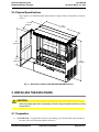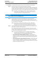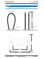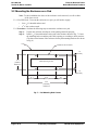
1
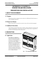
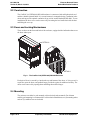
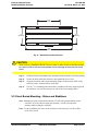
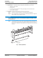
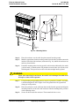
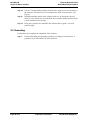
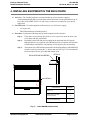
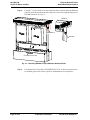
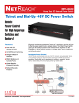
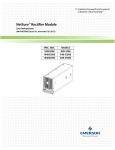
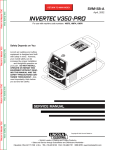
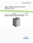
A technical manual from the experts
in Business-Critical Continuity™
NetReachTM CoolPed 3.0 Passive DSLAM Enclosure
Description and Installation
631-200-108 (Version B, March 18, 2013)
Business-Critical Continuity™, Emerson Network Power, and the Emerson Network
Power logo are trademarks and service marks of Emerson Electric Co.
NetSure™, NetSpan™, NetReach™, NetXtend™, and NetPerform™
are trademarks of Emerson Network Power, Energy Systems, North America, Inc.
All other trademarks are the property of their respective owners.
The products covered by this instruction manual are manufactured and/or
sold by Emerson Network Power, Energy Systems, North America, Inc.
The information contained in this document is subject to change without notice and may not be
suitable for all applications. While every precaution has been taken to ensure the accuracy and
completeness of this document, Emerson Network Power, Energy Systems, North America, Inc.
assumes no responsibility and disclaims all liability for damages resulting from use of this information
or for any errors or omissions. Refer to other local practices or building codes as applicable for the correct
methods, tools, and materials to be used in performing procedures not specifically described in this document.
This document is the property of Emerson Network Power, Energy Systems, North America, Inc.
and contains confidential and proprietary information owned by Emerson Network Power, Energy
Systems, North America, Inc. Any copying, use or disclosure of it without the written permission
of Emerson Network Power, Energy Systems, North America, Inc. is strictly prohibited.
Copyright © 2013, Emerson Network Power, Energy Systems, North America, Inc.
All rights reserved throughout the world.
Emerson Network Power
Buried Distribution Products
631-200-108
Version B, March 18, 2013
TABLE OF CONTENTS
1. ABOUT THIS DOCUMENT
1
1.1
Purpose . . . . . . . . . . . . . . . . . . . . . . . . . . . . . . . . . . . . . . . . . . . . . . . . . . . . . . . . . . . . . .
1
1.2
Reason for Reissue . . . . . . . . . . . . . . . . . . . . . . . . . . . . . . . . . . . . . . . . . . . . . . . . . . . . .
1
1.3
Additional Information . . . . . . . . . . . . . . . . . . . . . . . . . . . . . . . . . . . . . . . . . . . . . . . . . . .
1
2. DESCRIPTION
1
2.1
Application . . . . . . . . . . . . . . . . . . . . . . . . . . . . . . . . . . . . . . . . . . . . . . . . . . . . . . . . . . . .
1
2.2
Construction . . . . . . . . . . . . . . . . . . . . . . . . . . . . . . . . . . . . . . . . . . . . . . . . . . . . . . . . . .
2
2.3
Doors and Locking Mechanisms . . . . . . . . . . . . . . . . . . . . . . . . . . . . . . . . . . . . . . . . . . .
2
2.4
Mounting . . . . . . . . . . . . . . . . . . . . . . . . . . . . . . . . . . . . . . . . . . . . . . . . . . . . . . . . . . . . .
2
2.5
Physical Specifications . . . . . . . . . . . . . . . . . . . . . . . . . . . . . . . . . . . . . . . . . . . . . . . . . .
3
3. INSTALLING THE ENCLOSURE
3
3.1
Preparation . . . . . . . . . . . . . . . . . . . . . . . . . . . . . . . . . . . . . . . . . . . . . . . . . . . . . . . . . . .
3
3.2
Mounting the Enclosure on a Pad . . . . . . . . . . . . . . . . . . . . . . . . . . . . . . . . . . . . . . . . . .
6
3.3
Direct Buried Mounting - Stakes and Stabilizers . . . . . . . . . . . . . . . . . . . . . . . . . . . . . . .
7
3.4
Grounding . . . . . . . . . . . . . . . . . . . . . . . . . . . . . . . . . . . . . . . . . . . . . . . . . . . . . . . . . . . .
10
4. INSTALLING EQUIPMENT IN THE ENCLOSURE
11
5. REVISION RECORD
14
Outside Plant Equipment
Proprietary Information
Page i of ii
631-200-108
Version B, March 18, 2013
Emerson Network Power
Buried Distribution Products
This Page Left Intentionally Blank
Page ii of ii
Proprietary Information
Outside Plant Equipment
Emerson Network Power
Buried Distribution Products
631-200-108
Version B, March 18, 2013
NETREACHTM COOLPED 3.0
PASSIVE DSLAM ENCLOSURE
DESCRIPTION AND INSTALLATION
1. ABOUT THIS DOCUMENT
1.1 Purpose
This practice provides a description of the CoolPed 3.0 (CPED1844) DSLAM Enclosure as
well as installation instructions.
1.2 Reason for Reissue
Whenever this practice is reissued, the reason for reissue will be stated in this paragraph.
1.3 Additional Information
The information contained in this practice is subject to change without notice and may not be
suitable for all applications. Always follow local practices and procedures as applicable for
procedures not specifically described in this practice.
2. DESCRIPTION
2.1 Application
The CoolPed 3.0 (CPED1844)
DSLAM enclosure (shown in Fig. 1)
houses environmentally-hardened
electronics. It can accommodate up to
four customer-supplied Digital
Subscriber Line Access Multiplexers
(DSLAMs), two in the front and two in
the back, an optional Emerson AC
Power Kit (ACPOWKIT F1007112),
and various accessories as may be
required by your specific application.
Generous ventilation in the enclosure
doors and cap provide the necessary air
flow for multiple DSLAM’s.
Fig. 1 : The CoolPed DSLAM Enclosure
Outside Plant Equipment
Proprietary Information
Page 1 of 14
631-200-108
Version B, March 18, 2013
Emerson Network Power
Buried Distribution Products
2.2 Construction
The CoolPed 3.0 (CPED1844) DSLAM enclosure is constructed with mill-galvanized steel
and has a durable painted finish. It is a round cornered, rectangular design, ventilation in the
doors and cap provide optimal ventilation for up to four weather hardened DSLAM's. To ease
installation, the lower cover can be removed by loosening the hex head bolts inside the base
and lifting the cover up.
2.3 Doors and Locking Mechanisms
There are doors on the front and back of the enclosure, equipped with wind latches that secure
the doors when open.
see DETAIL A
DETAIL A
Fig. 2 : The CoolPed 3.0 (CPED 1844) DSLAM Enclosure
Each pair of doors is secured by a latch at the top and bottom of the doors. A 216-type tool is
required to open the doors, and padlock hasps provide the option for additional security. The
doors can be removed by opening them and lifting them off the hinges.
2.4 Mounting
The enclosure can either be pad mounted or direct buried (stake mounted). For ultimate
stability, pad mounting is recommended. For direct buried installation, two (2) mounting stakes
and two (2) stabilizer bars are included.
Page 2 of 14
Proprietary Information
Outside Plant Equipment
Emerson Network Power
Buried Distribution Products
631-200-108
Version B, March 18, 2013
2.5 Physical Specifications
The CoolPed 3.0 (CPED1844) DSLAM enclosure weighs 195 lbs. Its dimensions are shown
in Fig. 3.
17.8
(453mm)
43.8
(1112mm)
34.0
(864mm)
10.0
(253mm)
48.0
(1219mm)
Fig. 3 : Dimensions CoolPed 3.0 (CPED1844) DSLAM Enclosure
3. INSTALLING THE ENCLOSURE
CAUTION
Notify the proper personnel, and perform all local safety procedures before installing
the enclosure.
3.1 Preparation
3.1.1 You Will Need - To prepare the enclosure for mounting, you will need cable caps and tape (if
the cable will not be looped through the enclosure).
Outside Plant Equipment
Proprietary Information
Page 3 of 14
631-200-108
Version B, March 18, 2013
Emerson Network Power
Buried Distribution Products
3.1.2 Procedure - Perform the following steps to prepare for the installation of the enclosure:
Step 1:
Place the enclosure as shown on the construction work prints.
The cable or cables are normally placed on the trench line. When offsetting cables
from the cable trench, the engineer needs to specify each location for the DSLAM
enclosures and needs to indicate on the construction drawings the amount of offset.
Note: If possible, avoid offsetting an enclosure from the trench line. Offset
cables of this type are difficult to locate, and the cables are often cut
when other excavations or cable placement occurs.
ALERT
When installed, the enclosure must be level.
Step 2:
Decide whether the enclosure will be mounted on a pad or direct buried.
When mounted on a pad, the top of the enclosure is about 48 inches (121.9 cm)
above the pad. When direct buried, the top of the enclosure is 44 to 46 inches (111.8
to 116.8 cm) above the final grade.
Step 3:
Note: Pad mounting offers the greatest stability and security. When direct
buried, you must exercise extra care in leveling the pedestal. If you do
not properly level a direct buried pedestal, operation may be affected.
At the enclosure location, place the cable as prescribed on the construction work
prints and in accordance with local practices.
Leave the appropriate amount of cable above the ground. The amount of cable
needed will vary depending on how the enclosure is mounted and on whether or not
the cable will be looped through the enclosure.
Note: If you will be installing the enclosure in a manner other than those
described in this section (Section 3.1), the engineer must specify the
amount of cable that is to be looped through the enclosure.
• If the cable will be looped through the enclosure, a cable loop that is a
minimum 90 inches (2.3 m) long, measured from the point the cable exits the
ground to the point it reenters the ground, should extend above the ground line.
(See Fig. 4)
• If the cable will not be looped through the enclosure, each end of the cable
should extend about a minimum of 36 inches (91 cm) above the ground line.
(See Fig. 5) Seal the open cable ends with cable caps and tape to prevent water
and dirt from entering the cable core.
Page 4 of 14
Proprietary Information
Outside Plant Equipment
Emerson Network Power
Buried Distribution Products
631-200-108
Version B, March 18, 2013
ALERT
Do not leave an excessive length of cable above the ground.
90 inches minimum
(2.3 m)
36 inches
(91 cm)
minimum
ground line
ground line
Fig. 4 : Cable Looped Through Enclosure
Fig. 5 : Cable Not Looped Through Enclosure
45.7
(1161mm)
43.8
(1113mm)
61.1
(1552mm)
Fig. 6 :
Recommended "Keep-Out" Area for CoolPed 3.0 Enclosure
Outside Plant Equipment
Proprietary Information
Page 5 of 14
631-200-108
Version B, March 18, 2013
Emerson Network Power
Buried Distribution Products
3.2 Mounting the Enclosure on a Pad
Note: To ease installation, the doors of the enclosure can be removed, as well as either
of the lower covers.
3.2.1 You Will Need - To mount the enclosure on a pad, you will need to supply:
•
•
four 1/2-13 threaded anchors and
a 3/4" hex socket wrench.
3.2.2 Procedure - Perform the following steps to mount the enclosure on a pad:
Step 1:
Step 2:
Unpack the enclosure and dispose of the packing materials properly.
Install 1/2-13 threaded anchors in the pad at the locations shown in Fig. 7. Center
the mounting holes around the pad’s cable opening or according to local practices.
(The slots on the bottom of the enclosure for the pad mounting hardware are shown
in Fig. 8)
Pad
Outside of the Enclosure
1.0
(25.4mm)
17.0
(432mm)
Reference
15.0
Cable Opening in Pad
1.0
(25.4mm)
11.1
(282mm)
21.0
(533mm)
11.1
(282mm)
43.2
(1097mm)
Reference
Fig. 7 : Pad Mounting Hole Centers
Page 6 of 14
Proprietary Information
Outside Plant Equipment
Emerson Network Power
Buried Distribution Products
631-200-108
Version B, March 18, 2013
21.0
(533mm)
15.0
(381mm)
17.0
(432mm)
43.2
(1098mm)
Fig. 8 : Bottom View of the Enclosure
CAUTION
When moving a CoolPed DSLAM Enclosure from its pallet to the installation location,
be careful to not let the enclosure bend or flex as damage to the enclosure could
result.
Step 3:
Step 4:
Step 5:
Step 6:
Slide the enclosure around the cable loop that extends from the pad’s cable opening.
Secure all cables inside the enclosure, and reattach the lower cover.
Align the four front and rear pad mounting flanges, located on the inside of the
enclosure’s base, with the anchors in the pad.
Use the 1/2-13 mounting bolts and washers, included in the loose parts bag inside
the enclosure, to secure the enclosure at each of the four mounting holes.
3.3 Direct Buried Mounting - Stakes and Stabilizers
Note: Mounting on a pad (as described in Section 3.2) offers the greatest stability for the
enclosure. If you are direct burying the enclosure, exercise care and extra
attention when leveling the enclosure.
Note: To ease installation, the doors of the enclosure can be removed, as well as either
of the lower covers.
Outside Plant Equipment
Proprietary Information
Page 7 of 14
631-200-108
Version B, March 18, 2013
Emerson Network Power
Buried Distribution Products
3.3.1 You Will Need - To mount the enclosure using stakes and stabilizers, you will need:
•
•
•
•
equipment to dig a trench;
a 216-type tool;
a 9/16" hex socket wrench and a 9/16"hex open end type or box end wrench; and
a rubber mallet or hammer.
3.3.2 Procedure - Perform the following steps to direct bury the enclosure:
Step 1:
Step 2:
Unpack the enclosure and dispose of the packing materials properly.
Dig a rectangular hole with approximately the following dimensions: Length: 50
inches; Width: 30 inches; Depth: 10 inches.
ALERT
There should be about 5 inches (13 cm) between the bottom of the doors and the
finished grade level.
Step 3:
To mount the stabilizers (one per side), locate kit inside enclosure packaging. Using
four hex head 1/4-14 screws per side. Attach the stabilizer to the lower cover as
shown in Fig. 9. Bottom fin of the stabilizers are to be positioned outwards from the
enclosure.
stabilizer
Fig. 9 : Mounting Stabilizers
Page 8 of 14
Proprietary Information
Outside Plant Equipment
Emerson Network Power
Buried Distribution Products
631-200-108
Version B, March 18, 2013
holes for attaching
mounting stake to
enclosure
mounting
stakes
Fig. 10 : Mounting Stakes
Step 4:
Step 5:
Step 6:
Place the enclosure over the cable loop that extends from the ground.
Mark the approximate locations on the ground where the stakes would mount on the
inside of each side of the enclosure (as shown in Fig. 10), and lift the enclosure out
and away from the hole.
Pound the mounting stakes into the ground, in the locations indicated by the marks
you have made, so that the stakes will protrude at least 4 inches (10 cm) above the
finished grade. Take special care to drive the stakes straight into the ground.
WARNING
When stake mounting the enclosure, be careful not to damage the cable when
driving the stakes into the ground.
Step 7:
Step 8:
Step 9:
If local bonding and grounding practices require a ground rod, install it, and attach
a sufficient length of 6 AWG copper wire to the ground rod with a ground rod
clamp, per local practices.
Place the enclosure over the cable loop that extends from the ground, and align the
mounting locations on the side of the enclosure with the mounting holes provided
on the mounting stakes.
Secure all cables inside the enclosure. Then reattach the lower cover.
Outside Plant Equipment
Proprietary Information
Page 9 of 14
631-200-108
Version B, March 18, 2013
Emerson Network Power
Buried Distribution Products
Step 10: Use the 3/8-inch mounting hardware from the loose parts kit to secure the stakes to
the enclosure. The stakes are to be mounted on the inside of the enclosure. (See
Fig. 10)
Step 11: Backfill around the outside of the enclosure with soil. At final grade, the top 5
inches (13 cm) of the lower cover should be above ground, and the bottom 4 inches
(10 cm) should be below ground.
Step 12: Place gravel (preferred) or backfill in the enclosure base to grade, or as local
practices apply.
3.4 Grounding
Perform the step to complete the installation of the enclosure:
Step 1:
Page 10 of 14
Perform all bonding and grounding procedures according to local practices. A
ground bar is provided in the base of the enclosure.
Proprietary Information
Outside Plant Equipment
Emerson Network Power
Buried Distribution Products
631-200-108
Version B, March 18, 2013
4. INSTALLING EQUIPMENT IN THE ENCLOSURE
4.1 Overview - The CoolPed enclosure can accommodate up to four customer-supplied
weather-hardened DSLAMs, two in the front and two in the back, and an optional Emerson AC
Power Kit (ACPOWKIT F1007112), and various accessories as required by your specific
application.
4.2 You Will Need - To install equipment in the enclosure, you will need to supply:
•
•
a 216-type tool;
DSLAM manufacturer mounting bracket.
4.3 Procedure - Perform the following steps to install equipment in the enclosure:
Step 1:
Step 2:
Step 3:
If the doors are not already open, then use a 216-type tool to open the doors, and
secure them with the wind latches.
Depending on the DSLAM used, mounting to the horizontal rails will require
adaptor brackets to be supplied by the DSLAM provider. If required, affix brackets
to DSLAM per manufacturer requirements or local practice prior to mounting.
Relocate the lower DSLAM horizontal rail as needed depending on which DSLAM
module is used by loosening the 1/4" bolt on each end. See Fig. 11 for horizontal rail
location required for the given DSLAM module used.
DETAIL A
RELOCATE BAR AS NEEDED
A
B
C
see DETAIL A
EQUIPMENT
CONFIGURATION
BAR MOUNTING
POSITION
CALIX E3 - 48
A
ADTRAN TA1124 (1ST GEN)
& TA1148 (2ND GEN)
B
ADTRAN TA1148A/V (3RD GENERATION)
& TA1148 (4TH GENERATION)
C
Fig. 11 : Lower DSLAM Horizontal Rail
Outside Plant Equipment
Proprietary Information
Page 11 of 14
631-200-108
Version B, March 18, 2013
Step 4:
Emerson Network Power
Buried Distribution Products
Using the 1/4-14 hex head screws provided in the loose parts kit, attach the DSLAM
to the top and bottom horizontal rails using two screws each top and bottom (4 per
DSLAM mounted). See Fig. 12.
DETAIL A
see DETAIL A
wind latch
1/4-14 hex head screws
Fig. 12 : Attaching DSLAM to Top and Bottom Horizontal Rails
Step 5:
Page 12 of 14
If an Emerson AC Power Kit (ACPOWKIT F1007112), or other accessories are to
be installed, please refer to their respective documentation or local practice.
Proprietary Information
Outside Plant Equipment
Emerson Network Power
Buried Distribution Products
631-200-108
Version B, March 18, 2013
NOTES
Outside Plant Equipment
Proprietary Information
Page 13 of 14
631-200-108
Version B, March 18, 2013
Emerson Network Power
Buried Distribution Products
5. REVISION RECORD
Issue
Change
Number
(ECO)
A
RWN216612
New
B
RRM218470
Updates on CoolPed 3.0 CPED1844 cabinet design.
Page 14 of 14
Description of Change
Proprietary Information
Outside Plant Equipment
NetPerform™ Optimization Services
At Emerson Network Power, we understand the importance of reliable equipment – it’s critical to both
your business and your bottom line. That is why we offer a wide array of services to meet all of your
network infrastructure needs.
Technical Support
Email
Phone
[email protected]
[email protected]
1.800.800.5260
Answers technical product and system
questions; determines status of warranties and
contractual agreements for repair.
Services - Design, Deployment & Optimization
Email
[email protected]
Phone
1.800.800.1280, option 7
FreedomCare Secure.EmersonNetworkPower.com
Provides quotes and bid responses, order
placement and scheduling for design, and
deployment and optimization services.
Download service & maintenance reports
online.
Spare Parts
Email
Phone
[email protected]
[email protected]
1.800.800.1280, option 5
Pricing and PO processing of spare parts,
including but not limited to breakers, cables,
fuses, rectifier fans, misc. breaker and fuse
panels, enclosure fans, doors & switches, etc.
DC Power Depot Repair
Email
[email protected]
Phone
1.800.800.1280, option 6
Creates and processes RMAs, determines lead
times and pricing, provides repair shipping
information and status.
DC Power Product Training
Email
Phone
[email protected] Requests for quotes, order placement and
scheduling.
1.800.800.1280, option 8
For More Information
To learn more about service offerings from Emerson Network Power, please contact your sales
representative, call 1-800-800-1280 option 7, email [email protected] or visit
www.EmersonNetworkPower.com/EnergySystems.
Emerson (NYSE: EMR), based in St. Louis, is a global leader in bringing technology and engineering together to provide
innovative solutions to customers through its network power, process management, industrial automation, climate
technologies, and appliance and tools businesses. For more information, visit: Emerson.com.
Emerson Network Power, a business of Emerson (NYSE:EMR), is the global leader in enabling Business-Critical Continuity™
from grid to chip for telecommunication networks, data centers, health care and industrial facilities. Emerson Network
Power provides innovative solutions and expertise in areas including AC and DC power, precision cooling systems,
embedded computing and power, integrated racks and enclosures, power switching and controls, monitoring, and
connectivity. All solutions are supported globally by local Emerson Network Power service technicians. For more
information on Emerson Network Power’s full suite of solutions specifically supporting the communications network
infrastructure, including NetSpan™, NetReach™ and NetXtend™ outside plant enclosures and equipment, NetSure™ DC
power systems, and turnkey services, visit: EmersonNetworkPower.com/EnergySystems.
Learn more about Emerson Network Power products and services at: EmersonNetworkPower.com.
Emerson Network Power
Energy Systems, North America, Inc.
4350 Weaver Parkway, Warrenville, IL 60555
Toll Free: 800-800-1280 (USA and Canada)
Telephone: 440-246-6999 Fax: 440-246-4876
Web: EmersonNetworkPower.com/EnergySystems
EnergyNet: Secure.EmersonNetworkPower.com
Emerson Network Power.
The global leader in enabling Business-Critical Continuity™ .
AC Power
Connectivity
DC Power
Emerson Network Power.com/EnergySystems
Embedded Computing
Embedded Power
Outside Plant
Power Switching & Controls
Racks & Integrated Cabinets
Services
Infrastructure Management & Monitoring
Precision Cooling
Surge Protection